styleview sit stand combo system, with worksurface and ... · to accomodate extra weight, the...
TRANSCRIPT
888-45-205-W-04 rev.N • 10/141 of 22
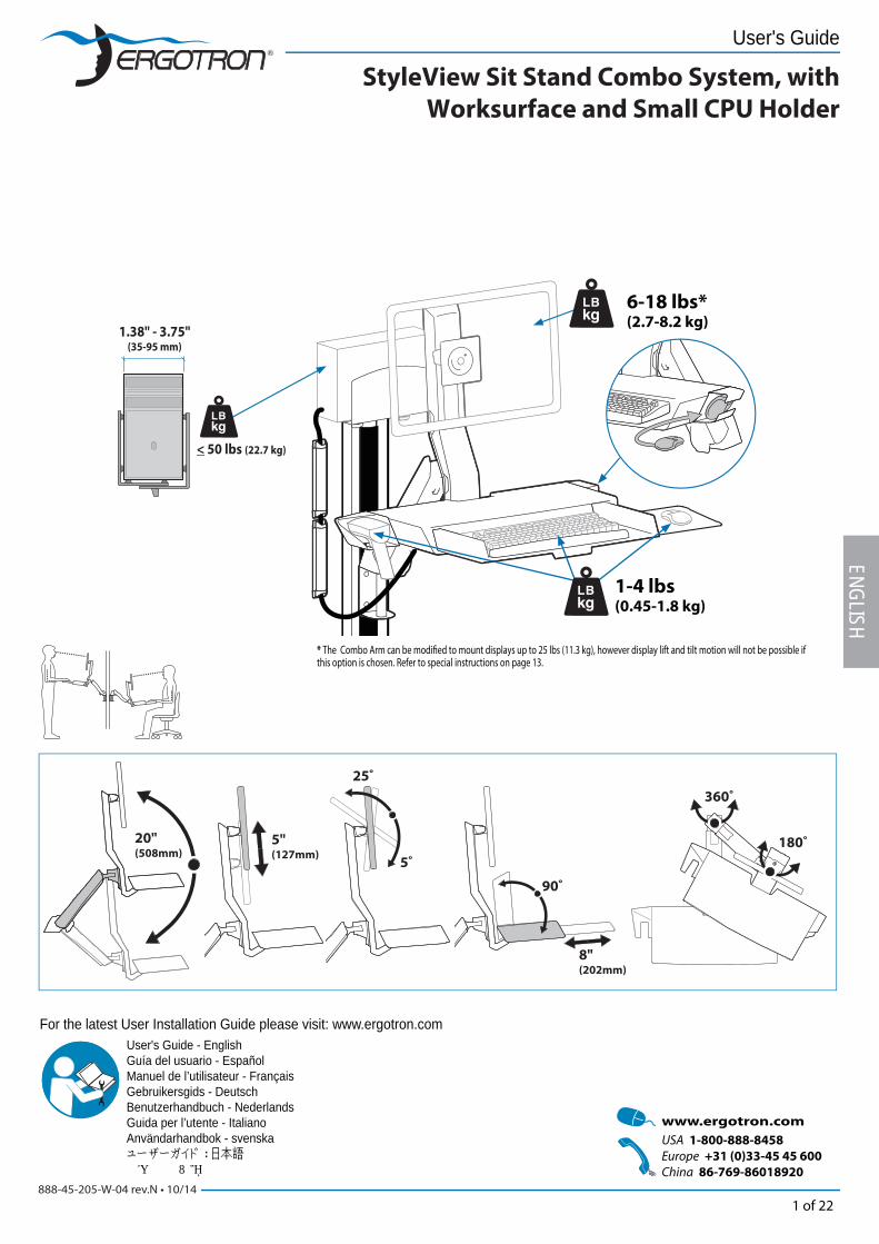
StyleView Sit Stand Combo System, with
Worksurface and Small CPU Holder
< 50 lbs (22.7 kg)
90˚
8"(202mm)
180˚
360˚
20"(508mm)
5"(127mm)
25˚
5˚
1.38" - 3.75"(35-95 mm)
6-18 lbs*(2.7-8.2 kg)
1-4 lbs(0.45-1.8 kg)
User's Guide - EnglishGuía del usuario - EspañolManuel de l’utilisateur - FrançaisGebruikersgids - DeutschBenutzerhandbuch - NederlandsGuida per l’utente - ItalianoAnvändarhandbok - svenskaユーザーガイド : 日本語用户指南 : 汉语
ENGLISH
For the latest User Installation Guide please visit: www.ergotron.com
User's Guide
* The Combo Arm can be modifi ed to mount displays up to 25 lbs (11.3 kg), however display lift and tilt motion will not be possible if this option is chosen. Refer to special instructions on page 13.
888-45-205-W-04 rev.N • 10/142 of 22
Ø 3/8" (10 mm) Ø 1/2" (12.8 mm)Ø 7/32" (5.6 mm)
21
10mm11 mm13 mm7/16"
1/4”
ENGL
ISH
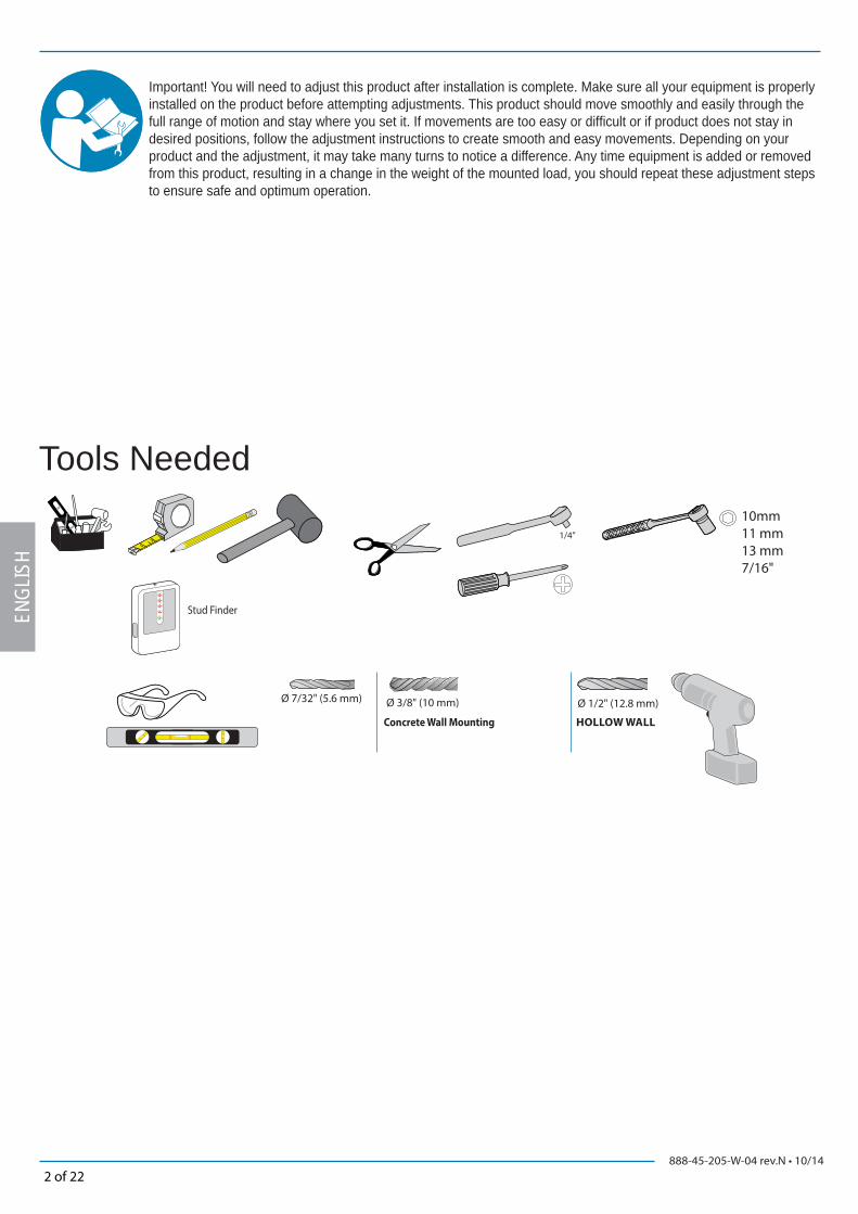
Important! You will need to adjust this product after installation is complete. Make sure all your equipment is properly installed on the product before attempting adjustments. This product should move smoothly and easily through the full range of motion and stay where you set it. If movements are too easy or diffi cult or if product does not stay in desired positions, follow the adjustment instructions to create smooth and easy movements. Depending on your product and the adjustment, it may take many turns to notice a difference. Any time equipment is added or removed from this product, resulting in a change in the weight of the mounted load, you should repeat these adjustment steps to ensure safe and optimum operation.
Tools Needed
Stud Finder
Concrete Wall Mounting HOLLOW WALL

888-45-205-W-04 rev.N • 10/143 of 22
A B C D E
1
2
3
4
5
6
7
8
9
1x
1x
1x
1x
1x
4x
3x
2x
1x
1x
1x
M4 x 10mm
4x
M4 x 10mm
4x
2xM6 x 10mm
2x 8x
M6 x 70mm M4.2 x 25mm
10x 4x
10x10x
6 mm
3 mm
10x
M6
2x
2x
2x
4x
1/4-20 x 2"
10x
7x
7x
2x
M5 x 15mm
4x
1x
1x
1x
1x
1x
1x
1x
1x1x1x
M8 x 16mm
8x
1x
1x
M3.5 x 8mm
2x
8mm1x
1x
M4 x 8mm
2x
M4 x 6mm
M4 x 10mm
2x
4x
M10 x 18mm
2x
M10 x 16mm
ENGLISH
Components
Optional Weight Capacity Modifi cation Fasteners
888-45-205-W-04 rev.N • 10/144 of 22
1
6”
(152 mm)
5’3”-5’9”(160-175cm)
21”(533 mm)
28.5”(724mm)< 27.5”
(699mm)
9.2”(232mm)
11.9”(301mm)
9.5”(241mm)
22.7”(575mm)
31.9”(810mm)
17”(430mm)
12.5”(318mm)
ENGL
ISH
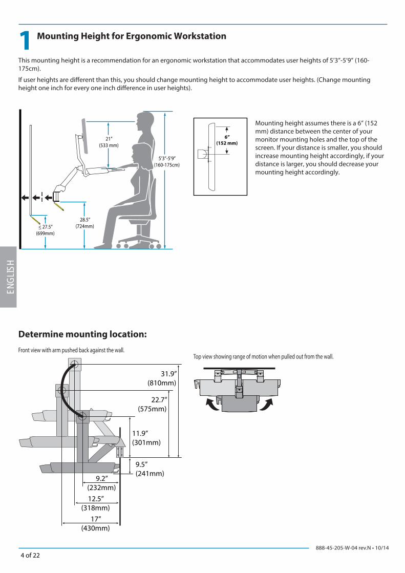
Mounting Height for Ergonomic Workstation
This mounting height is a recommendation for an ergonomic workstation that accommodates user heights of 5’3”-5’9” (160-175cm).
If user heights are diff erent than this, you should change mounting height to accommodate user heights. (Change mounting height one inch for every one inch diff erence in user heights).
Mounting height assumes there is a 6” (152 mm) distance between the center of your monitor mounting holes and the top of the screen. If your distance is smaller, you should increase mounting height accordingly, if your distance is larger, you should decrease your mounting height accordingly.
Determine mounting location:
Top view showing range of motion when pulled out from the wall.Front view with arm pushed back against the wall.
888-45-205-W-04 rev.N • 10/145 of 22
2
6 8
10x 10x
10x
10x
Ø 3/8" (10 mm) Ø 1/2"
1/4-20 x 2"
10x M6
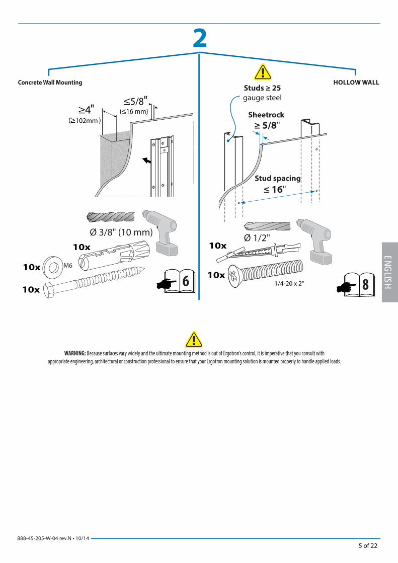
≤ 16"
Studs ≥ 25
gauge steel
≥ 5/8"Sheetrock
Stud spacing
ENGLISH
Concrete Wall Mounting HOLLOW WALL
WARNING: Because surfaces vary widely and the ultimate mounting method is out of Ergotron’s control, it is imperative that you consult with
appropriate engineering, architectural or construction professional to ensure that your Ergotron mounting solution is mounted properly to handle applied loads.

888-45-205-W-04 rev.N • 10/146 of 22
2
a
b
c
3-1/8"(80 mm)
x 10
x 10
ENGL
ISH
Concrete Wall Mounting
WARNING:
Mounting holes must be at least 3-1/8” (80mm) deep and must be located within solid
concrete, not mortar or covering material. If you drill into an area of concrete that is
not solid, reposition mounting holes until both anchors can be fully inserted into solid
concrete!
WARNING:
Anchors that are not fully set in solid concrete will not support the applied load
resulting in an unstable, unsafe condition which could lead to personal injury
and/or property damage. Consult a construction professional if you have any
doubt about what this means in regard to your particular situation.
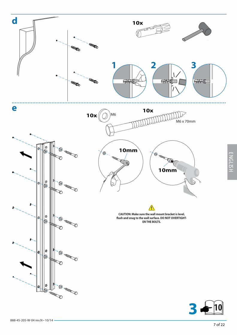
888-45-205-W-04 rev.N • 10/147 of 22
10x
1 2 3
10x
M6 x 70mm
10mm
10mm
10x M6
103
d
e
ENGLISH
CAUTION: Make sure the wall mount bracket is level,
fl ush and snug to the wall surface. DO NOT OVERTIGHT-
EN THE BOLTS.

888-45-205-W-04 rev.N • 10/148 of 22
2
a cb
10x
≤ 16"
Studs ≥ 25 gauge steel
≥ 5/8"Sheetrock
Stud spacing
ENGL
ISH
HOLLOW WALL
Requires minimum material thickness of 5/8” (16 mm).
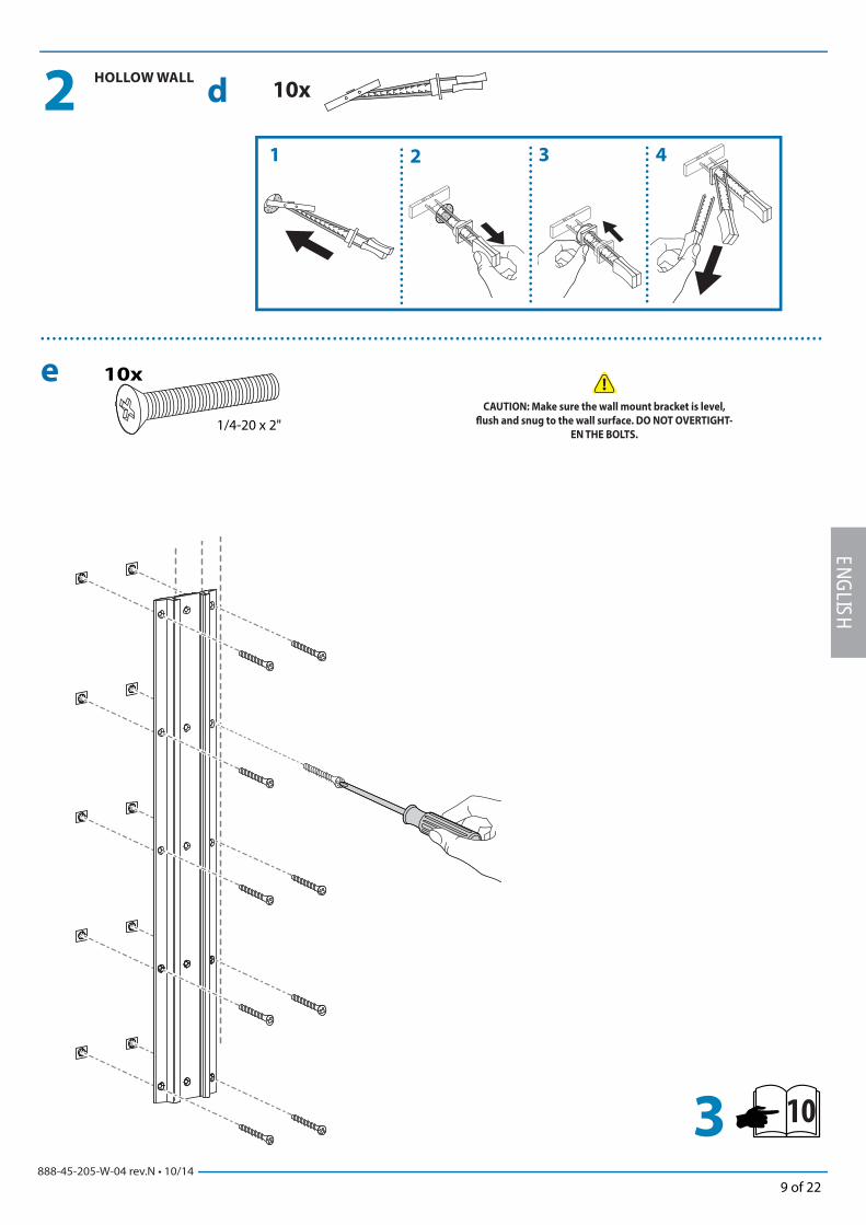
888-45-205-W-04 rev.N • 10/149 of 22
103
d
e
1 2 3 4
10x
10x
1/4-20 x 2"
2
ENGLISH
HOLLOW WALL
CAUTION: Make sure the wall mount bracket is level,
fl ush and snug to the wall surface. DO NOT OVERTIGHT-
EN THE BOLTS.
888-45-205-W-04 rev.N • 10/1410 of 22
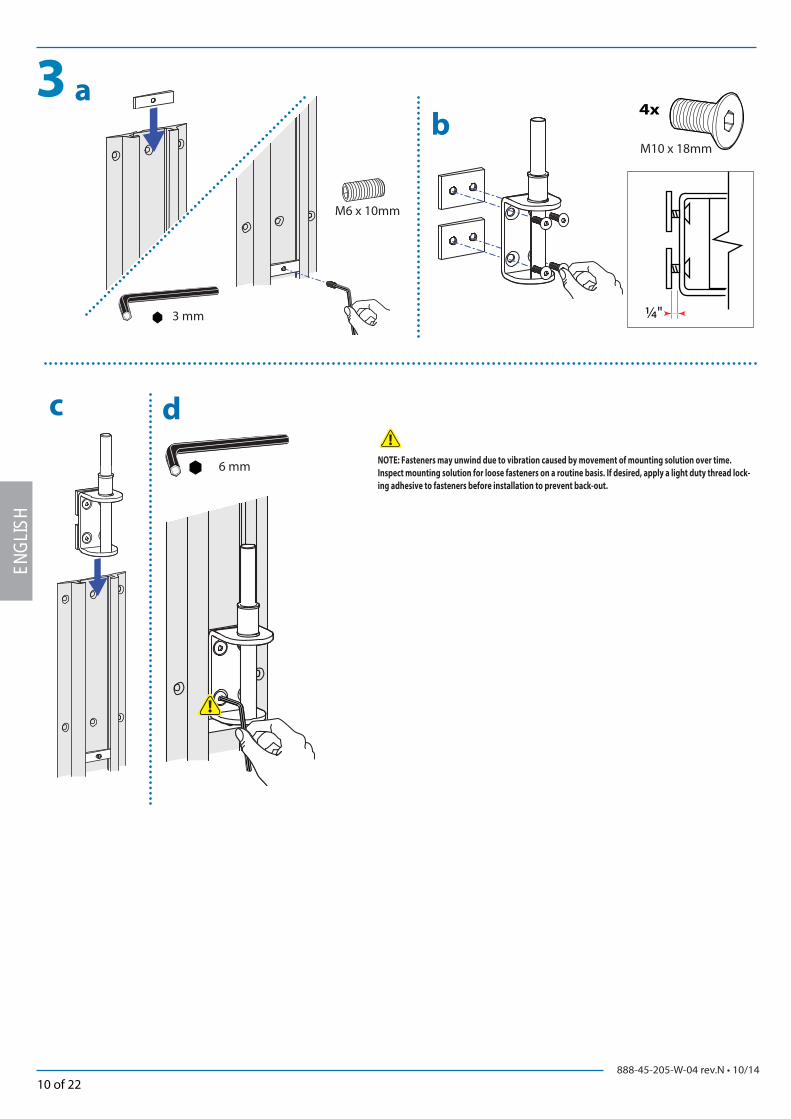
3 a
c d
b
M6 x 10mm
6 mm
3 mm
4x
M10 x 18mm
¼"
ENGL
ISH
NOTE: Fasteners may unwind due to vibration caused by movement of mounting solution over time.
Inspect mounting solution for loose fasteners on a routine basis. If desired, apply a light duty thread lock-
ing adhesive to fasteners before installation to prevent back-out.
888-45-205-W-04 rev.N • 10/1411 of 22
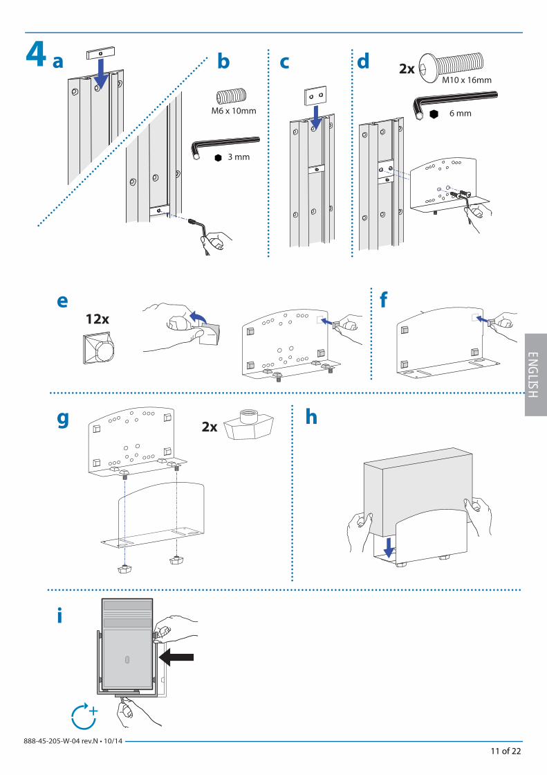
4 a
6 mm
12x
2xg
i
h
e f
b c d
M6 x 10mm
3 mm
2xM10 x 16mm
ENGLISH
888-45-205-W-04 rev.N • 10/1412 of 22
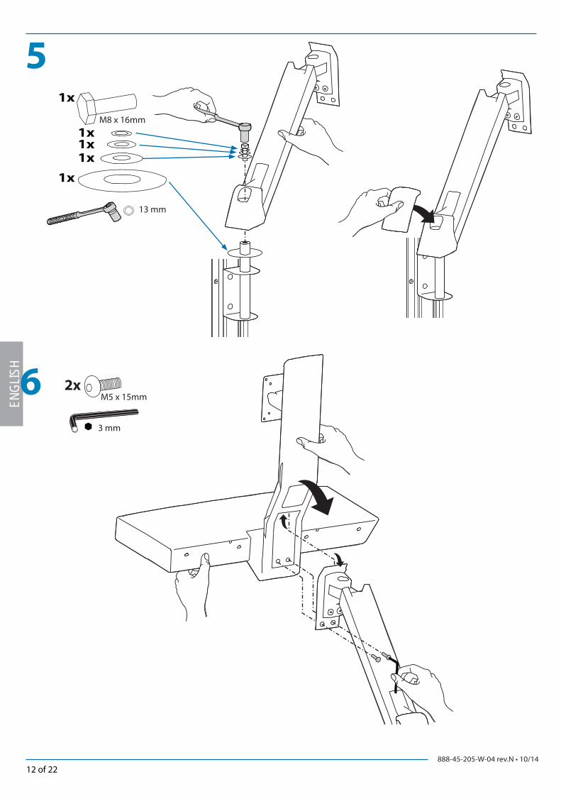
5
6
13 mm
2xM5 x 15mm
1x
1x
1x1x1x
M8 x 16mm
3 mm
ENGL
ISH
888-45-205-W-04 rev.N • 10/1413 of 22
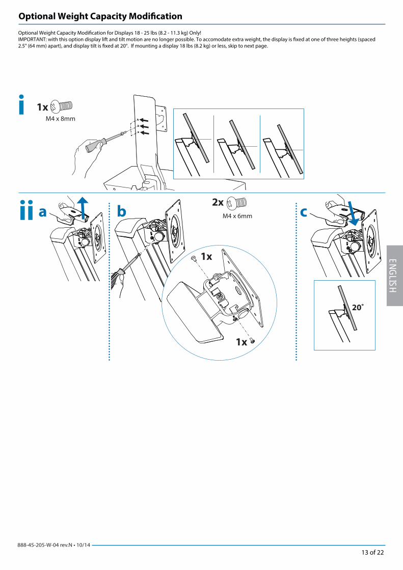
2x
M4 x 6mm
1xM4 x 8mm
1x
1x
20˚
a c b
i
ii
ENGLISH
Optional Weight Capacity Modifi cation for Displays 18 - 25 lbs (8.2 - 11.3 kg) Only!IMPORTANT: with this option display lift and tilt motion are no longer possible. To accomodate extra weight, the display is fi xed at one of three heights (spaced 2.5" (64 mm) apart), and display tilt is fi xed at 20°. If mounting a display 18 lbs (8.2 kg) or less, skip to next page.
Optional Weight Capacity Modifi cation
888-45-205-W-04 rev.N • 10/1414 of 22
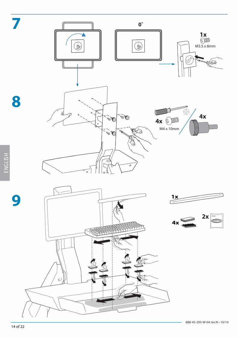
4x4x
M4 x 10mm
8
7
2x4x
1x9
0˚
1x
M3.5 x 8mm
ENGL
ISH

888-45-205-W-04 rev.N • 10/1415 of 22
11
10
12
13
1x 1x
2x
ENGLISH
NOTE: Leave enough slack in cable to allow full range of motion.
Caution:
To avoid the potential to pinch cables it is important to follow the cable routing instructions in this manual. Failure to
follow these instructions may result in equipment damage or personal injury.
888-45-205-W-04 rev.N • 10/1416 of 22
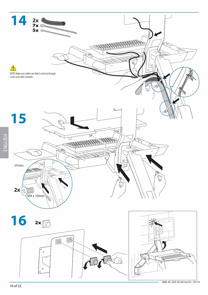
14 7x5x
2x
15
16 2x
OPTIONAL:
M4 x 10mm
2x
ENGL
ISH
NOTE: Make sure cables can slide in and out through covers and cable channels.

888-45-205-W-04 rev.N • 10/1417 of 22
17
a
f
c d
g he
b
M4.2 x 25mm M4.2 x 25mm
M4.2 x 25mm4x 2x 2x 2x
2x
Ø 7/32" (xx mm) .21875
Flush with drywal1 2 3
4x
2x
1x 1x
2x 2x 2x
ENGLISH
CAUTION: Make sure there is enough clearance between back of mounted component and cable channel. Failure to allow clearance space may result in personal injury and equipment damage.
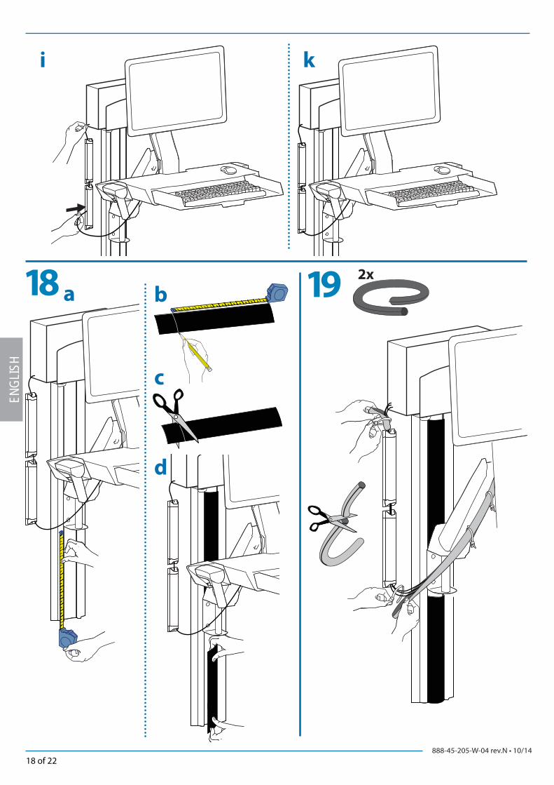
888-45-205-W-04 rev.N • 10/1418 of 22
i k
18 a b
c
d
192x
ENGL
ISH
888-45-205-W-04 rev.N • 10/1419 of 22
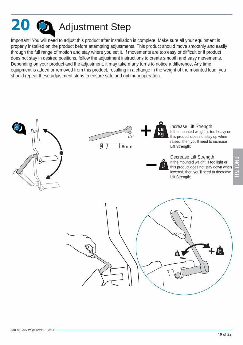
20
a
1/4”
8mm
ENGLISH
Increase Lift StrengthIf the mounted weight is too heavy or this product does not stay up when raised, then you'll need to increase Lift Strength:
Decrease Lift StrengthIf the mounted weight is too light or this product does not stay down when lowered, then you'll need to decrease Lift Strength:
Adjustment StepImportant! You will need to adjust this product after installation is complete. Make sure all your equipment is properly installed on the product before attempting adjustments. This product should move smoothly and easily through the full range of motion and stay where you set it. If movements are too easy or diffi cult or if product does not stay in desired positions, follow the adjustment instructions to create smooth and easy movements. Depending on your product and the adjustment, it may take many turns to notice a difference. Any time equipment is added or removed from this product, resulting in a change in the weight of the mounted load, you should repeat these adjustment steps to ensure safe and optimum operation.
888-45-205-W-04 rev.N • 10/1420 of 22
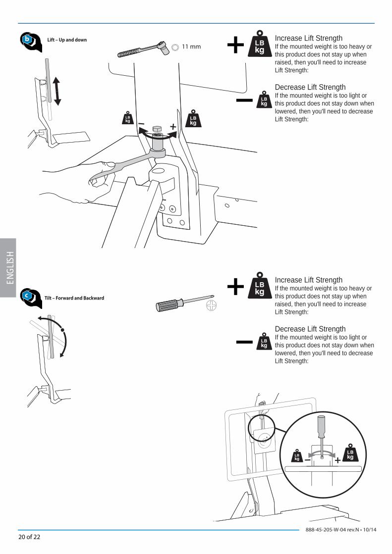
c
b11 mm
ENGL
ISH
Tilt – Forward and Backward
Increase Lift StrengthIf the mounted weight is too heavy or this product does not stay up when raised, then you'll need to increase Lift Strength:
Decrease Lift StrengthIf the mounted weight is too light or this product does not stay down when lowered, then you'll need to decrease Lift Strength:
Increase Lift StrengthIf the mounted weight is too heavy or this product does not stay up when raised, then you'll need to increase Lift Strength:
Decrease Lift StrengthIf the mounted weight is too light or this product does not stay down when lowered, then you'll need to decrease Lift Strength:
Lift – Up and down
888-45-205-W-04 rev.N • 10/1421 of 22
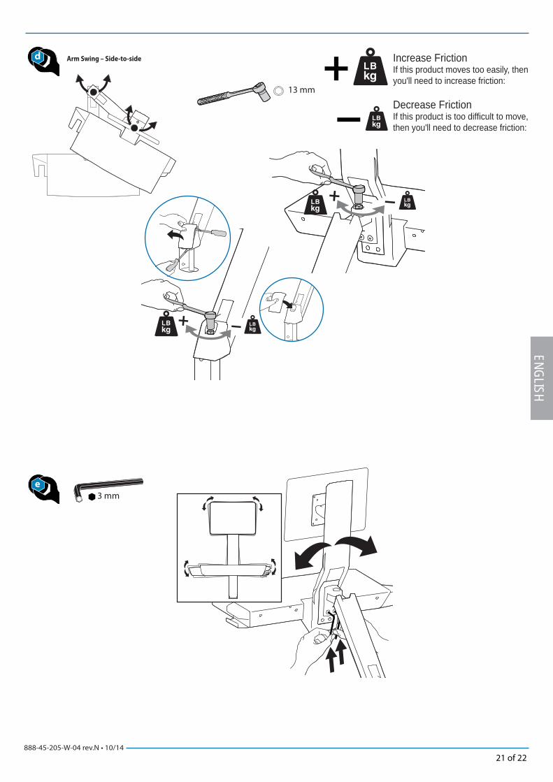
3 mm
d
e
13 mm
ENGLISH
Arm Swing – Side-to-side Increase FrictionIf this product moves too easily, then you'll need to increase friction:
Decrease FrictionIf this product is too diffi cult to move, then you'll need to decrease friction:
888-45-205-W-04 rev.N • 10/1422 of 22
ENGL
ISH
For local customer care phone numbers visit: http://contact.ergotron.com
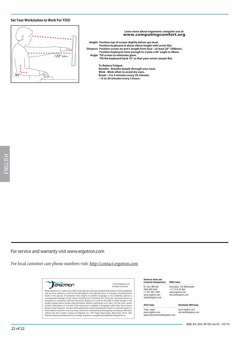
Learn more about ergonomic computer use at:
www.computingcomfort.org
Set Your Workstation to Work For YOU!
Height Position top of screen slightly below eye level. Position keyboard at about elbow height with wrists fl at. Distance Position screen an arm's length from face—at least 20” (508mm). Position keyboard close enough to create a 90˚ angle in elbow. Angle Tilt screen to eliminate glare. Tilt the keyboard back 10° so that your wrists remain fl at.
To Reduce FatigueBreathe - Breathe deeply through your nose.Blink - Blink often to avoid dry eyes.Break • 2 to 3 minutes every 20 minutes• 15 to 20 minutes every 2 hours.