studying the kinetics of crystalline silicon nanoparticle ... ill ryu , seok woo lee , chongmin wang...
TRANSCRIPT

www.advmat.dewww.MaterialsViews.com
CO
MM
UN
ICATIO
Matthew T. McDowell , Ill Ryu , Seok Woo Lee , Chongmin Wang , William D. Nix , and Yi Cui *
Studying the Kinetics of Crystalline Silicon Nanoparticle Lithiation with In Situ Transmission Electron Microscopy
N
Silicon has attracted signifi cant attention for use as the negative electrode material in Li-ion batteries [ 1–5 ] in part because it has a specifi c capacity about ten times that of commercial graphite. In contrast to traditional intercalation electrodes, Si and Li react via an alloying process, which results in an enormous ( ∼ 300%) volume expansion due to the uptake of up to 4.4 Li atoms per Si atom in the fully alloyed material. [ 6 , 7 ] This large volume change is a fundamental issue that has hindered the widespread use of Si in batteries. Concentration gradients associated with volume expansion can cause signifi cant mechanical stress to exist within electrode structures, which can lead to fracture and elec-trical isolation of the active material. [ 8–11 ] In addition, volume expansion/contraction of Si structures can promote unstable growth of the solid-electrolyte-interphase (SEI), which results in high ionic resistance and poor cycling performance. [ 12 ] Frac-ture compounds this issue: the SEI grows on the new surfaces of a fractured electrode particle, which could promote electrical isolation since the SEI is electronically insulating. [ 13 ] In short, the volume changes during Li alloying/dealloying are the cause of many problems associated with this system, so it is vital to understand the fundamental nature of these volume changes and how they relate to the reaction itself.
The electrochemical properties of the Li-Si system have been studied for more than three decades, [ 14 , 15 ] but research on the effects of volume expansion has only been performed more recently. [ 7 , 16 ] In the past few years, a number of studies have specifi cally focused on lithiation and volume changes in crystal-line Si nanostructures. The lithiation of crystalline Si is a two-phase reaction in which a reaction front separates the growing
© 2012 WILEY-VCH Verlag Gm
Prof. Y. CuiDepartment of Materials Science and EngineeringStanford UniversityStanford, CA 94305USA, and Stanford Institute for Materials and Energy SciencesSLAC National Accelerator Laboratory2575 Sand Hill Road, Menlo Park, CA 94025, USA E-mail: [email protected] M. T. McDowell, I. Ryu, Dr. S. W. Lee, Prof. W. D. NixDepartment of Materials Science and EngineeringStanford UniversityStanford, CA 94305, USA Dr. C. M. WangEnvironmental Molecular Sciences LaboratoryPacifi c Northwest National LaboratoryRichland, WA 99354, USA
DOI: 10.1002/adma.201202744
Adv. Mater. 2012, DOI: 10.1002/adma.201202744
Li x Si amorphous phase from pristine crystalline Si. [ 17–19 ] The Li concentration increases abruptly at the reaction front, which has nanoscale thickness. [ 20 ] This is a different physical process than the lithiation of amorphous Si, which progresses via a single-phase reaction and is thought to be diffusion-controlled. [ 21 ] A number of experimental studies have shown that crystalline Si undergoes anisotropic lithiation and volume expansion, with preferential expansion occurring perpendicular to {110} crystal-lographic planes. [ 22–24 ] This phenomenon has been proposed to be due to differing reaction rates at different crystallographic surfaces of crystalline Si, [ 25–27 ] which is qualitatively similar to anisotropic etching of Si single crystals. The observation of ani-sotropic expansion in these experiments strongly suggests that the lithiation kinetics of crystalline Si nanostructures are con-trolled by the rate of the reaction at the interface rather than by diffusion through the lithiated phase. [ 26 , 27 ]
Other studies have shown that in addition to causing frac-ture, the mechanical stress generated during Li insertion can affect the nature of the Li-Si reaction. Experimental work has revealed that biaxial stresses exceeding 1.5 GPa exist during lithiation and delithiation of amorphous Si thin fi lms; [ 28 ] these stresses are much higher than in conventional intercalation-type electrodes and can signifi cantly alter the thermodynamics of the Li-Si system. [ 29 , 30 ] In a recent study, Zhao et al. developed an analytical model encompassing volume expansion and plastic deformation that describes the stress evolution in spherical crystalline Si nanoparticles during lithiation. [ 26 ] Interestingly, this study predicts that the stress that arises in a crystalline par-ticle during lithiation acts in thermodynamic opposition to the electrochemical driving force for the reaction between Li and Si; this means that the stress could affect both the electrochemical potential and the reaction rate. In addition, the stresses present during the lithiation of Si have been shown to depend on the shape and the crystallinity of the structure of interest. [ 9 , 11 , 26 , 31 ]
From the preceding discussion, it is clear that the lithiation of crystalline Si is a complex process in which the diffusion of Li, the reaction rates at different surfaces, and the mechanical stress all play roles. A comprehensive understanding of how these factors infl uence the lithiation process is necessary for better control of the electrochemical characteristics of Si elec-trodes, but it is diffi cult to probe the dynamic aspects of such a reaction using conventional ex situ experimental techniques. In this work, we overcome this limitation by using in situ trans-mission electron microscopy (TEM) to observe the lithiation of crystalline Si nanoparticles in real-time, and we measure and analyze the time-dependence of the lithiation-induced deforma-tion to reveal that mechanical stress plays a signifi cant role in governing the kinetics of the reaction.
bH & Co. KGaA, Weinheim 1wileyonlinelibrary.com
www.advmat.dewww.MaterialsViews.com
CO
MM
UN
ICATI
ON
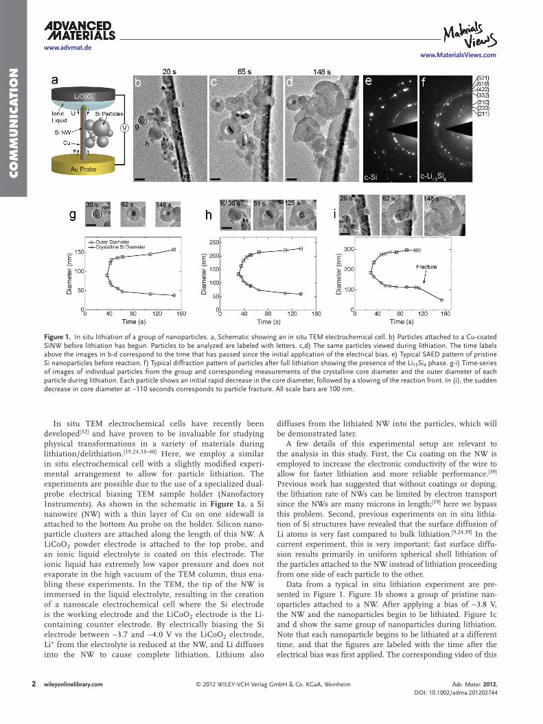
Figure 1 . In situ lithiation of a group of nanoparticles. a, Schematic showing an in situ TEM electrochemical cell. b) Particles attached to a Cu-coated SiNW before lithiation has begun. Particles to be analyzed are labeled with letters. c,d) The same particles viewed during lithiation. The time labels above the images in b-d correspond to the time that has passed since the initial application of the electrical bias. e) Typical SAED pattern of pristine Si nanoparticles before reaction. f) Typical diffraction pattern of particles after full lithiation showing the presence of the Li 15 Si 4 phase. g-i) Time-series of images of individual particles from the group and corresponding measurements of the crystalline core diameter and the outer diameter of each particle during lithiation. Each particle shows an initial rapid decrease in the core diameter, followed by a slowing of the reaction front. In (i), the sudden decrease in core diameter at ∼ 110 seconds corresponds to particle fracture. All scale bars are 100 nm.
In situ TEM electrochemical cells have recently been developed [ 32 ] and have proven to be invaluable for studying physical transformations in a variety of materials during lithiation/delithiation. [ 19 , 24 , 33–40 ] Here, we employ a similar in situ electrochemical cell with a slightly modifi ed experi-mental arrangement to allow for particle lithiation. The experiments are possible due to the use of a specialized dual-probe electrical biasing TEM sample holder (Nanofactory Instruments). As shown in the schematic in Figure 1 a, a Si nanowire (NW) with a thin layer of Cu on one sidewall is attached to the bottom Au probe on the holder. Silicon nano-particle clusters are attached along the length of this NW. A LiCoO 2 powder electrode is attached to the top probe, and an ionic liquid electrolyte is coated on this electrode. The ionic liquid has extremely low vapor pressure and does not evaporate in the high vacuum of the TEM column, thus ena-bling these experiments. In the TEM, the tip of the NW is immersed in the liquid electrolyte, resulting in the creation of a nanoscale electrochemical cell where the Si electrode is the working electrode and the LiCoO 2 electrode is the Li-containing counter electrode. By electrically biasing the Si electrode between − 3.7 and − 4.0 V vs the LiCoO 2 electrode, Li + from the electrolyte is reduced at the NW, and Li diffuses into the NW to cause complete lithiation. Lithium also
2 wileyonlinelibrary.com © 2012 WILEY-VCH Verlag
diffuses from the lithiated NW into the particles, which will be demonstrated later.
A few details of this experimental setup are relevant to the analysis in this study. First, the Cu coating on the NW is employed to increase the electronic conductivity of the wire to allow for faster lithiation and more reliable performance. [ 39 ] Previous work has suggested that without coatings or doping, the lithiation rate of NWs can be limited by electron transport since the NWs are many microns in length; [ 19 ] here we bypass this problem. Second, previous experiments on in situ lithia-tion of Si structures have revealed that the surface diffusion of Li atoms is very fast compared to bulk lithiation. [ 9 , 24 , 39 ] In the current experiment, this is very important: fast surface diffu-sion results primarily in uniform spherical shell lithiation of the particles attached to the NW instead of lithiation proceeding from one side of each particle to the other.
Data from a typical in situ lithiation experiment are pre-sented in Figure 1 . Figure 1 b shows a group of pristine nan-oparticles attached to a NW. After applying a bias of − 3.8 V, the NW and the nanoparticles begin to be lithiated. Figure 1 c and d show the same group of nanoparticles during lithiation. Note that each nanoparticle begins to be lithiated at a different time, and that the fi gures are labeled with the time after the electrical bias was fi rst applied. The corresponding video of this
GmbH & Co. KGaA, Weinheim Adv. Mater. 2012, DOI: 10.1002/adma.201202744
www.advmat.de
CO
MM
UN
ICATIO
N
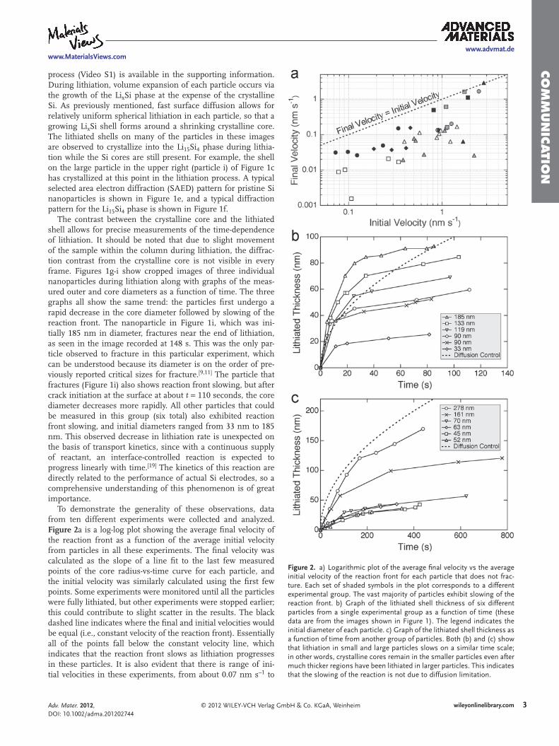
Figure 2 . a) Logarithmic plot of the average fi nal velocity vs the average initial velocity of the reaction front for each particle that does not frac-ture. Each set of shaded symbols in the plot corresponds to a different experimental group. The vast majority of particles exhibit slowing of the reaction front. b) Graph of the lithiated shell thickness of six different particles from a single experimental group as a function of time (these data are from the images shown in Figure 1 ). The legend indicates the initial diameter of each particle. c) Graph of the lithiated shell thickness as a function of time from another group of particles. Both (b) and (c) show that lithiation in small and large particles slows on a similar time scale; in other words, crystalline cores remain in the smaller particles even after much thicker regions have been lithiated in larger particles. This indicates that the slowing of the reaction is not due to diffusion limitation.
www.MaterialsViews.com
process (Video S1) is available in the supporting information. During lithiation, volume expansion of each particle occurs via the growth of the Li x Si phase at the expense of the crystalline Si. As previously mentioned, fast surface diffusion allows for relatively uniform spherical lithiation in each particle, so that a growing Li x Si shell forms around a shrinking crystalline core. The lithiated shells on many of the particles in these images are observed to crystallize into the Li 15 Si 4 phase during lithia-tion while the Si cores are still present. For example, the shell on the large particle in the upper right (particle i) of Figure 1 c has crystallized at this point in the lithiation process. A typical selected area electron diffraction (SAED) pattern for pristine Si nanoparticles is shown in Figure 1 e, and a typical diffraction pattern for the Li 15 Si 4 phase is shown in Figure 1 f.
The contrast between the crystalline core and the lithiated shell allows for precise measurements of the time-dependence of lithiation. It should be noted that due to slight movement of the sample within the column during lithiation, the diffrac-tion contrast from the crystalline core is not visible in every frame. Figures 1 g-i show cropped images of three individual nanoparticles during lithiation along with graphs of the meas-ured outer and core diameters as a function of time. The three graphs all show the same trend: the particles fi rst undergo a rapid decrease in the core diameter followed by slowing of the reaction front. The nanoparticle in Figure 1 i, which was ini-tially 185 nm in diameter, fractures near the end of lithiation, as seen in the image recorded at 148 s. This was the only par-ticle observed to fracture in this particular experiment, which can be understood because its diameter is on the order of pre-viously reported critical sizes for fracture. [ 9 , 11 ] The particle that fractures (Figure 1 i) also shows reaction front slowing, but after crack initiation at the surface at about t = 110 seconds, the core diameter decreases more rapidly. All other particles that could be measured in this group (six total) also exhibited reaction front slowing, and initial diameters ranged from 33 nm to 185 nm. This observed decrease in lithiation rate is unexpected on the basis of transport kinetics, since with a continuous supply of reactant, an interface-controlled reaction is expected to progress linearly with time. [ 19 ] The kinetics of this reaction are directly related to the performance of actual Si electrodes, so a comprehensive understanding of this phenomenon is of great importance.
To demonstrate the generality of these observations, data from ten different experiments were collected and analyzed. Figure 2 a is a log-log plot showing the average fi nal velocity of the reaction front as a function of the average initial velocity from particles in all these experiments. The fi nal velocity was calculated as the slope of a line fi t to the last few measured points of the core radius-vs-time curve for each particle, and the initial velocity was similarly calculated using the fi rst few points. Some experiments were monitored until all the particles were fully lithiated, but other experiments were stopped earlier; this could contribute to slight scatter in the results. The black dashed line indicates where the fi nal and initial velocities would be equal (i.e., constant velocity of the reaction front). Essentially all of the points fall below the constant velocity line, which indicates that the reaction front slows as lithiation progresses in these particles. It is also evident that there is range of ini-tial velocities in these experiments, from about 0.07 nm s − 1 to
3wileyonlinelibrary.com© 2012 WILEY-VCH Verlag GmbH & Co. KGaA, WeinheimAdv. Mater. 2012, DOI: 10.1002/adma.201202744
4
www.advmat.de
CO
MM
UN
ICATI
ON
3 nm s − 1 . Each shaded symbol in the plot corresponds to a dif-ferent experimental group, and the particles from each group exhibit similar initial velocities. The absolute velocity of the reaction front depends on a number of factors, including the electronic resistance of the NW framework to which the parti-cles are attached and the local ionic resistance at the electrolyte interface. Therefore, we think that variations of these values probably cause the initial velocity differences among the dif-ferent experiments. Regardless of the initial velocity, however, the fi nal velocity is usually lower.
At fi rst glance, the slowing trajectory of the shrinking core diameters as a function of time in Figure 1 g-i might be seen as evidence of a diffusion-limited reaction. However, recent anal-ysis has suggested that the lithiation of crystalline Si is a reac-tion-front limited process. [ 26 ] Here, the direct time-dependent measurements of the reaction front position during lithiation provide insight as to whether the reaction is diffusion-con-trolled. With planar geometry, diffusion limitation would result in a characteristic reacted length scale that is proportional to √
Dt , where D is the diffusivity and t is time. [ 41 ] With spherical geometry, the time-dependence of the characteristic diffusion length is qualitatively similar; slight differences are due to the concentrating effect of the spherical geometry, especially near the end of the diffusion process (see the supporting informa-tion for more details). Comparing the reaction kinetics in par-ticles with different sizes can yield useful information about whether the rate is controlled by diffusion or the interfacial reaction.
Figures 2 b and c are plots of the lithiated shell thickness of multiple nanoparticles as a function of time for two different in situ experiments. The lithiated shell thickness is used as the metric for comparison because it is the distance over which Li must diffuse during lithiation to react at the core interface. The TEM data for the group of particles in Figure 2 b are presented in Figure 1 , and the data for Figure 2 c are in the supporting information. The lithiated shell thickness was measured either until in situ observation ended or until the particles were fully lithiated (i.e., no crystalline core remaining). The dotted lines in Figure 2 b and 2 c represent the characteristic length scale for diffusion assuming a Li diffusivity in the shell of D = 10 − 16 m 2 s − 1 . [ 42 ] It is clear that the measured data behave dif-ferently: the lithiation rate slows in both smaller and larger par-ticles on similar time scales. For a diffusion-limited process, the smaller particles should be fully lithiated much faster than the larger particles, but here it is evident that the crystalline cores in the smaller particles are retained for longer than expected for diffusion limitation. From this data, it can be concluded that the total lithiated thickness is not the controlling factor for the slowing reaction front; the reaction front kinetics must be the rate-controlling feature.
If the kinetics of the reaction are controlled by the interface reaction rate instead of diffusion, the question now arises as to why the reaction rate decreases with extent of lithiation. Pre-vious in situ work has shown that the propagation of the Li x Si reaction front down the length of coated NWs is linear with time when the NWs are held at a constant potential. [ 19 , 39 ] How-ever, the “reaction front” in this case is the lithiation near the surface of the NW, which is usually followed by slower lithia-tion of the core region of the NW after the initial reaction front
wileyonlinelibrary.com © 2012 WILEY-VCH Verlag
www.MaterialsViews.com
passes. This is actually similar to the particle case, where the reaction slows as it progresses into the interior of the structure. For this interface-controlled reaction, the observed slowing of the reaction front must be due to changing reaction conditions at the interface between the crystalline Si core and the lithiated shell. Based on recent modeling efforts, [ 26 ] we show here that the effect of evolving mechanical stress at the reaction front on the driving force for reaction could be the factor that slows the lithiation rate.
In a recent noteworthy study, Zhao et al. develop an ana-lytical model to predict stress during the lithiation and volume expansion of crystalline Si. [ 26 ] This study assumes that the reac-tion is limited by the interface reaction rate and also allows for plastic deformation in the lithiated silicon. [ 20 ] The electrochem-ical lithiation of Si is represented as
Li + 1
xSi → 1
xLix Si
(1)
Each Li atom is presumed to react with pristine crystalline Si at the atomically sharp Li x Si/crystalline Si interface to form a new unit of lithiated silicon. The driving force for the consump-tion of one Li atom to form 1/x units of Li x Si is identifi ed as [ 26 ]
�G = �Gr − e� + 1
x
[σ Si
m �Si − σ Lix Sim �Lix Si
]
(2)
In this expression, Δ G is the net Gibbs free energy change, Δ G r is the free energy change with no mechanical stress or applied voltage, and Φ is the voltage applied to the electro-chemical cell. The term in brackets is the modifi cation to the net driving force due to the presence of mechanical stress in the structure: σ Si m is the mean stress in the Si core at the inter-face, σ Li x Si m is the mean stress in the lithiated silicon at the interface, and Ω Si and �Lix Si are the volumes per Si atom and unit of Li x Si, respectively. As written here, a negative Δ G drives lithiation. This means that compressive hydrostatic stress in the crystalline Si favors lithiation, while compressive hydrostatic stress in the lithiated silicon impedes lithiation. [ 26 ] By calcu-lating the stresses in the structure, we can use this expression to determine their effect on the driving force.
To model the stress during volume expansion and plastic deformation of spherical Si particles, Zhao et al. use a modifi ed version of calculations made by Hill. [ 43 ] Discussion of the stress profi les resulting from this model, along with similar results we obtained via fi nite element modeling for spherical lithia-tion, are presented in the supporting information. It should be noted that the stresses from this model are generally consistent with the fi nite element modeling in work by Liu et al. [ 9 ] The analytical model predicts that the crystalline core experiences homogeneous hydrostatic compression, which increases in magnitude as the core size decreases. The stress in the lithi-ated shell is inhomogeneous and triaxial (the radial and hoop stress values differ). At the Li x Si/Si interface, the hydrostatic stress in the shell is even more compressive than in the core, but it reverses and becomes tensile at the surface of the par-ticle due to the continual volume expansion at the reaction front that pushes out the already-lithiated material. The signifi -cant compression in the Li x Si directly adjacent to the Li x Si/Si interface can be physically understood because this material is
GmbH & Co. KGaA, Weinheim Adv. Mater. 2012, DOI: 10.1002/adma.201202744
www.advmat.dewww.MaterialsViews.com
CO
MM
UN
ICATIO
N
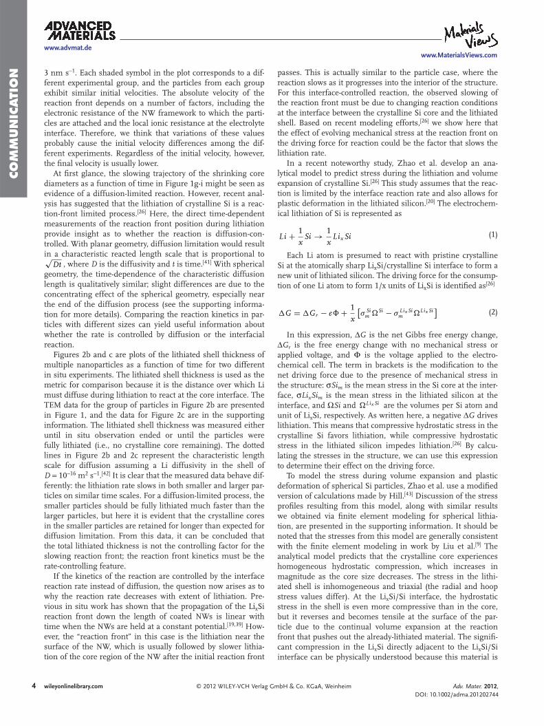
Figure 3 . a) Predicted mean stress evolution on either side of the Si/Li x Si interface in a spherical particle as it is lithiated. The inset is a schematic of a particle in the midst of lithiation, with a crystalline core radius a and an outer radius b . The extent of lithiation on the x -axis is denoted by the a/b ratio. The mean stress on both sides of the interface becomes more compressive as the size of the crystalline core decreases, with the stress in the shell at the interface always of greater magnitude than that in the core. b) The stress contribution to the Gibbs free energy of reaction as a function of a/b ratio. The stresses are calculated based on equations given in the supporting information, and assigning different values to the yield strength ( σ y ) of lithiated Si results in different curve trajectories. Here, two curves are calculated, with σ y = 1 GPa and σ y = 0.5 GPa. The actual behavior probably lies somewhere between these curves. c) a/b ratio as a function of time for the group of particles shown in Figure 1 . Particles of different size show reaction front slowing at similar a/b ratios, which suggests that the stress that builds up in the particles as the a/b ratio decreases is the controlling factor that causes the reaction front to slow. The legend shows the initial diameter of each particle.
constrained by the core as it expands and plastically deforms according to the yield criterion.
An important result of this model is that the magnitude of the stresses evolve with the extent of lithiation: the hydrostatic stresses on either side of the Li x Si/Si interface (the stresses that contribute to Δ G in Equation 2 ) become more compressive as the crystalline core shrinks, as shown in Figure 3 a. In this fi gure, the extent of lithiation is represented by the a/b ratio, where b is the outer radius of the particle and a is the radius of the crystalline core (see schematic inset). Details regarding cal-culations for this fi gure are contained in the supporting infor-mation. The difference between the hydrostatic stress values on each side of the Si/Li x Si interface at a specifi c a/b value is always constant, but the magnitude of the compressive stress increases substantially with decreasing core size. The signifi cant increase in pressure in the vicinity of the reaction front represents changing conditions that could affect the propagation velocity of the front, as suggested by Zhao et al. and detailed next.
Based on the stress calculation in Figure 3 a, the stress con-tribution to the driving force (the part of Equation (2) that is in brackets) as a function of a/b for reaction of a single par-ticle is shown in Figure 3 b. In this model, the yield strength assigned to the Li x Si signifi cantly affects the calculated curve. The yield strength for lithiated silicon has been variously reported to be between about 0.5 GPa and 1.5 GPa. [ 20 , 28 , 44 ] Here we calculate the stress contribution to the driving force for two different values of the yield strength, 0.5 and 1 GPa, with the understanding that the actual behavior may lie somewhere between these curves (see supporting information for calcula-tion details). From Figure 3 b, it is clear that the changing stress during lithiation causes the stress contribution to the Gibbs free energy to become more positive, as previously shown by Zhao et al. [ 26 ] Looking again at Equation (2) , the increasingly positive stress contribution to Δ G reduces the total driving force for the reaction, since the combined chemical and electrical driving force (the fi rst two terms in the equation) is negative. If we assume the velocity of the reaction front depends expo-nentially on the driving force, as in transition state theory, [ 26 ] this decrease in driving force would result in a decrease in reac-tion front velocity as the particle is lithiated, which is what is observed in the experiments. According to the modeling, the stress contribution is large enough to cause the total driving force to disappear at some value of a/b , which would cause the reaction front to halt. In the experiments, this was not observed: the reaction front sometimes slowed signifi cantly, but never completely stopped. This discrepancy could be due to i) an overestimate of the stress effect due to simplifi cations used in the model or ii) possible viscoplastic behavior in the lithiated silicon, where time-dependent stress relaxation might also alter the driving force.
The results from this model are in good qualitative agree-ment with the in situ experimental data. A distinguishing fea-ture of the model is that the slowing of the reaction front should depend primarily on the a/b ratio (the fractional extent of lithi-ation), not the actual lithiated thickness (as in diffusion con-trol). This is evident in the experimental data: in each particle group, particles of all sizes usually show slowing of the reaction front at similar values of a/b , as shown in Figure 3 c. While the value of a/b at which slowing occurs is usually similar among
5wileyonlinelibrary.com© 2012 WILEY-VCH Verlag GmbH & Co. KGaA, WeinheimAdv. Mater. 2012, DOI: 10.1002/adma.201202744
6
www.advmat.dewww.MaterialsViews.com
CO
MM
UN
ICATI
ON
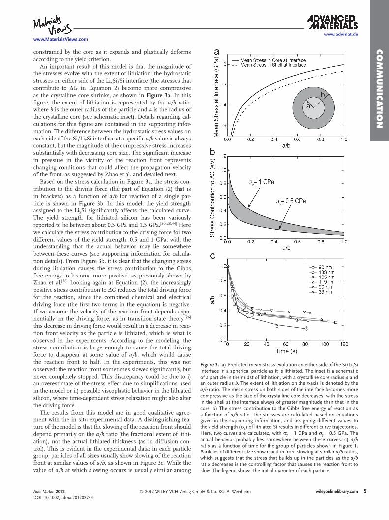
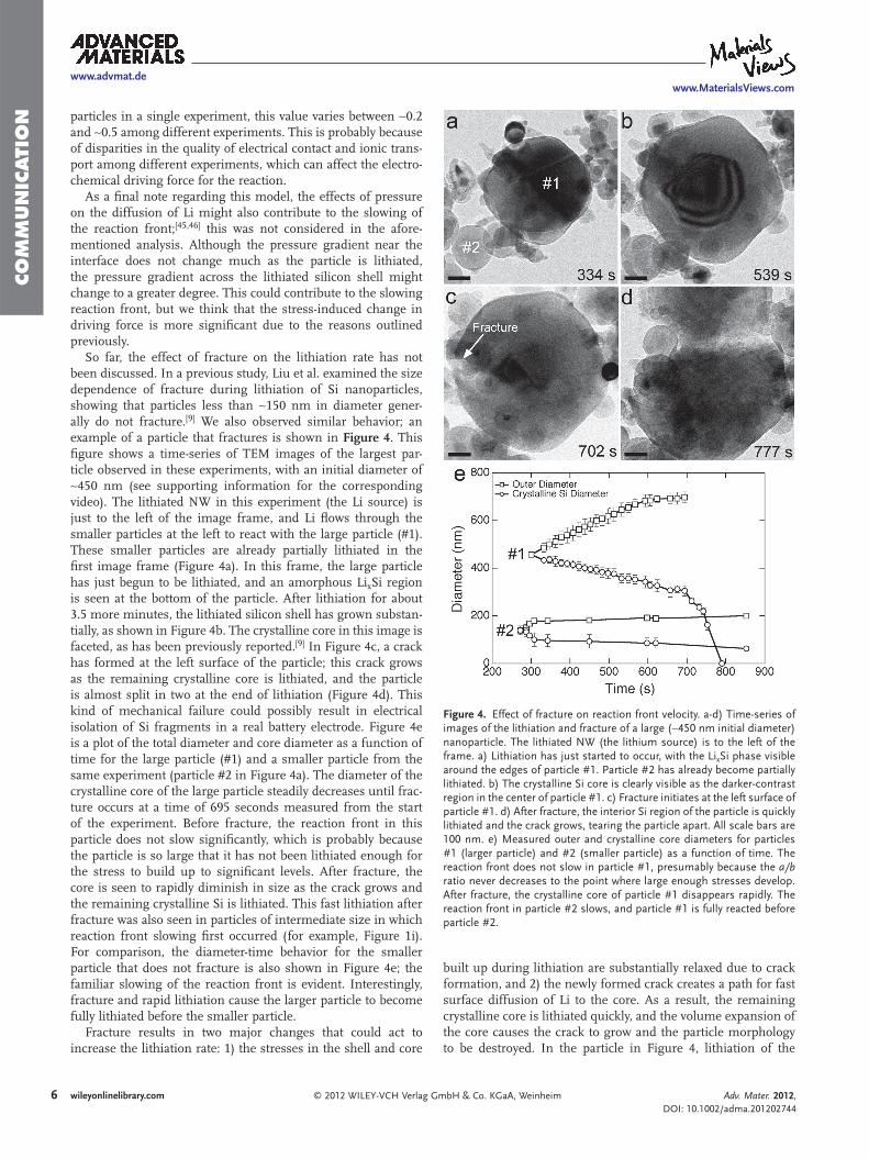
Figure 4 . Effect of fracture on reaction front velocity. a-d) Time-series of images of the lithiation and fracture of a large ( ∼ 450 nm initial diameter) nanoparticle. The lithiated NW (the lithium source) is to the left of the frame. a) Lithiation has just started to occur, with the Li x Si phase visible around the edges of particle #1. Particle #2 has already become partially lithiated. b) The crystalline Si core is clearly visible as the darker-contrast region in the center of particle #1. c) Fracture initiates at the left surface of particle #1. d) After fracture, the interior Si region of the particle is quickly lithiated and the crack grows, tearing the particle apart. All scale bars are 100 nm. e) Measured outer and crystalline core diameters for particles #1 (larger particle) and #2 (smaller particle) as a function of time. The reaction front does not slow in particle #1, presumably because the a/b ratio never decreases to the point where large enough stresses develop. After fracture, the crystalline core of particle #1 disappears rapidly. The reaction front in particle #2 slows, and particle #1 is fully reacted before particle #2.
particles in a single experiment, this value varies between ∼ 0.2 and ∼ 0.5 among different experiments. This is probably because of disparities in the quality of electrical contact and ionic trans-port among different experiments, which can affect the electro-chemical driving force for the reaction.
As a fi nal note regarding this model, the effects of pressure on the diffusion of Li might also contribute to the slowing of the reaction front; [ 45 , 46 ] this was not considered in the afore-mentioned analysis. Although the pressure gradient near the interface does not change much as the particle is lithiated, the pressure gradient across the lithiated silicon shell might change to a greater degree. This could contribute to the slowing reaction front, but we think that the stress-induced change in driving force is more signifi cant due to the reasons outlined previously.
So far, the effect of fracture on the lithiation rate has not been discussed. In a previous study, Liu et al. examined the size dependence of fracture during lithiation of Si nanoparticles, showing that particles less than ∼ 150 nm in diameter gener-ally do not fracture. [ 9 ] We also observed similar behavior; an example of a particle that fractures is shown in Figure 4 . This fi gure shows a time-series of TEM images of the largest par-ticle observed in these experiments, with an initial diameter of ∼ 450 nm (see supporting information for the corresponding video). The lithiated NW in this experiment (the Li source) is just to the left of the image frame, and Li fl ows through the smaller particles at the left to react with the large particle (#1). These smaller particles are already partially lithiated in the fi rst image frame (Figure 4 a). In this frame, the large particle has just begun to be lithiated, and an amorphous Li x Si region is seen at the bottom of the particle. After lithiation for about 3.5 more minutes, the lithiated silicon shell has grown substan-tially, as shown in Figure 4 b. The crystalline core in this image is faceted, as has been previously reported. [ 9 ] In Figure 4 c, a crack has formed at the left surface of the particle; this crack grows as the remaining crystalline core is lithiated, and the particle is almost split in two at the end of lithiation (Figure 4 d). This kind of mechanical failure could possibly result in electrical isolation of Si fragments in a real battery electrode. Figure 4 e is a plot of the total diameter and core diameter as a function of time for the large particle (#1) and a smaller particle from the same experiment (particle #2 in Figure 4 a). The diameter of the crystalline core of the large particle steadily decreases until frac-ture occurs at a time of 695 seconds measured from the start of the experiment. Before fracture, the reaction front in this particle does not slow signifi cantly, which is probably because the particle is so large that it has not been lithiated enough for the stress to build up to signifi cant levels. After fracture, the core is seen to rapidly diminish in size as the crack grows and the remaining crystalline Si is lithiated. This fast lithiation after fracture was also seen in particles of intermediate size in which reaction front slowing fi rst occurred (for example, Figure 1 i). For comparison, the diameter-time behavior for the smaller particle that does not fracture is also shown in Figure 4 e; the familiar slowing of the reaction front is evident. Interestingly, fracture and rapid lithiation cause the larger particle to become fully lithiated before the smaller particle.
Fracture results in two major changes that could act to increase the lithiation rate: 1) the stresses in the shell and core
wileyonlinelibrary.com © 2012 WILEY-VCH Verlag G
built up during lithiation are substantially relaxed due to crack formation, and 2) the newly formed crack creates a path for fast surface diffusion of Li to the core. As a result, the remaining crystalline core is lithiated quickly, and the volume expansion of the core causes the crack to grow and the particle morphology to be destroyed. In the particle in Figure 4 , lithiation of the
mbH & Co. KGaA, Weinheim Adv. Mater. 2012, DOI: 10.1002/adma.201202744

www.advmat.dewww.MaterialsViews.com
CO
MM
UN
ICATIO
N
remaining crystalline Si appears to occur directionally since the Li is now primarily fl owing from the fractured area; this would cause the stress state to differ from that in a particle evenly lithiated from all surfaces. This might be the reason why the reaction of the core does not appear to slow as the core is lithi-ated after fracture.
In summary, in situ TEM experiments of the lithiation of crys-talline Si nanoparticles have been presented, and the kinetics of lithiation have been analyzed at the single-particle level. From measurements of the reaction front position during lithiation, it was found that the reaction front usually slows as it progresses into the particles. We suggest that the changing mechanical stress at the reaction front as lithiation proceeds alters the total driving force for reaction and results in the observed slowing, in accordance with a previous modeling study. [ 26 ] Large stresses arise because of the extreme volume change that occurs at the two-phase interface separating crystalline and lithiated Si, and the particle shape dictates the stress evolution during lithiation. This phenomenon is unique to crystalline Si and need not be considered for phase transformations in conventional battery materials due to much smaller mechanical stresses and strains in these systems. Also, it is well known that after the fi rst lithia-tion, initially crystalline Si remains amorphous during cycling. The stresses and strain that develop during lithiation and del-ithiation of amorphous Si are expected to be much different than for crystalline Si; [ 21 ] as such, it is important to understand the interrelated effects of stress, diffusion, and particle mor-phology on the kinetics and thermodynamics of the reaction in both crystalline and amorphous Si. Nevertheless, we hope this research will contribute to the search for the optimum struc-ture, morphology, and cycling conditions for good electrochem-ical performance.
Experimental Section The in situ TEM experiments were conducted in an FEI Titan microscope with a Nanofactory Instruments Dual-Probe STM-TEM in situ sample holder. The NWs used in the experiments were grown with the vapor-liquid-solid method on Si wafers using 50 nm Au nanoparticles as the catalyst (40 sccm SiH 4 fl ow rate, 40 Torr pressure of 2% SiH 4 in Ar, 490 ° C, 12 minutes growth time). After growth, a ∼ 30 nm Cu layer was deposited on the NWs with thermal evaporation. The Si nanoparticles were purchased from Sigma-Aldrich. Since the as-received Si nanoparticles had a fairly thick ( ∼ 5–10 nm) oxide shell, it was removed with HF etching before the experiments were performed for consistency. However, experiments on nanoparticles with oxide revealed similar reaction front slowing behavior. The ionic liquid electrolyte consisted of 10 wt% lithium bis(trifl uoromethylsulfonyl) imide (LiTFSI) in a solvent of 1-butyl-1-methylpyrrolidinium bis(trifl uoromethylsulfonyl) imide (P 14 TFSI). During imaging, the beam was kept at low intensity, which has been found to be effective for avoiding beam effects. [ 9 ]
Supporting Information Supporting Information is available from the Wiley Online Library or from the author.
Acknowledgements M.T.M. acknowledges support from the Chevron Stanford Graduate Fellowship, the National Defense Science and Engineering Graduate
© 2012 WILEY-VCH Verlag GmAdv. Mater. 2012, DOI: 10.1002/adma.201202744
Fellowship, and the National Science Foundation Graduate Fellowship. Portions of this work are supported by the U.S. Department of Energy, Offi ce of Basic Energy Sciences, Division of Materials Sciences and Engineering under Contract No. DE-AC02-76SF00515 through the SLAC National Accelerator Laboratory LDRD project and the Assistant Secretary for Energy effi ciency and Renewable Energy, Offi ce of Vehicle Technologies of the U.S. Department of Energy under Contract No. DE-AC02-05CH11231, Subcontract No. 6951379 under the Batteries for Advanced Transportation Technologies (BATT) Program. S.W.L. acknowledges support from KAUST (No. KUK-F1-038-02). C.M.W. acknowledges support from the Laboratory Directed Research and Development (LDRD) program of Pacifi c Northwest National Laboratory. The in situ TEM work was conducted in the William R. Wiley Environmental Molecular Sciences Laboratory (EMSL), a national scientifi c user facility sponsored by DOE’s Offi ce of Biological and Environmental Research and located at PNNL. PNNL is operated by Battelle for the DOE under Contract DE-AC05-76RLO1830. W.D.N. and I.R. gratefully acknowledge support of the Offi ce of Science, Offi ce of Basic Energy Sciences, of the US Department of Energy under contract no. DE-FG02-04ER46163. The authors would like to thank Dr. Mauro Pasta for helpful comments.
Received: July 6, 2012 Revised: August 7, 2012
Published online:
[ 1 ] U. Kasavajjula , C. S. Wang , A. J. Appleby , J. Power Sources 2007 , 163 , 1003 .
[ 2 ] C. K. Chan , H. L. Peng , G. Liu , K. McIlwrath , X. F. Zhang , R. A. Huggins , Y. Cui , Nat. Nanotechnol. 2008 , 3 , 31 .
[ 3 ] I. Kovalenko , B. Zdyrko , A. Magasinski , B. Hertzberg , Z. Milicev , R. Burtovyy , I. Luzinov , G. Yushin , Science 2011 , 334 , 75 .
[ 4 ] M. S. Whittingham , MRS Bull. 2008 , 33 , 411 . [ 5 ] L. F. Cui , R. Ruffo , C. K. Chan , H. L. Peng , Y. Cui , Nano Lett. 2009 , 9 ,
491 . [ 6 ] M. N. Obrovac , L. Christensen , Electrochem. Solid-State Lett. 2004 ,
7 , A93 . [ 7 ] L. Y. Beaulieu , T. D. Hatchard , A. Bonakdarpour , M. D. Fleischauer ,
J. R. Dahn , J. Electrochem. Soc. 2003 , 150 , A1457 . [ 8 ] L. Y. Beaulieu , K. W. Eberman , R. L. Turner , L. J. Krause , J. R. Dahn ,
Electrochem. Solid-State Lett. 2001 , 4 , A137 . [ 9 ] X. H. Liu , L. Zhong , S. Huang , S. X. Mao , T. Zhu , J. Y. Huang , ACS
Nano 2012 , 6 , 1522 . [ 10 ] R. A. Huggins , W. D. Nix , Ionics 2000 , 6 , 57 . [ 11 ] S. W. Lee , M. T. McDowell , L. A. Berla , W. D. Nix , Y. Cui , Proc. Natl.
Acad. Sci. USA 2012 , 109 , 4080 . [ 12 ] H. Wu , G. Chan , J. W. Choi , I. Ryu , Y. Yao , M. T. McDowell , S. W. Lee ,
A. Jackson , Y. Yang , L. Hu , Y. Cui , Nat. Nanotechnol. 2012 , 7 , 310 . [ 13 ] J. Christensen , J. Newman , J. Solid State Electrochem. 2006 , 10 , 293 . [ 14 ] S.-C. Lai , J. Electrochem. Soc. 1976 , 123 , 1196 . [ 15 ] C. J. Wen , R. A. Huggins , J. Solid State Chem. 1981 , 37 , 271 . [ 16 ] A. Timmons , J. R. Dahn , J. Electrochem. Soc. 2007 , 154 , A444 . [ 17 ] P. Limthongkul , Y. I. Jang , N. J. Dudney , Y. M. Chiang , Acta Mater.
2003 , 51 , 1103 . [ 18 ] B. Key , M. Morcrette , J.-M. Tarascon , C. P. Grey , J. Am. Chem. Soc.
2010 , 133 , 503 . [ 19 ] X. H. Liu , L. Q. Zhang , L. Zhong , Y. Liu , H. Zheng , J. W. Wang ,
J.-H. Cho , S. A. Dayeh , S. T. Picraux , J. P. Sullivan , S. X. Mao , Z. Z. Ye , J. Y. Huang , Nano Lett. 2011 , 11 , 2251 .
[ 20 ] M. J. Chon , V. A. Sethuraman , A. McCormick , V. Srinivasan , P. R. Guduru , Phys. Rev. Lett. 2011 , 107 , 045503 .
[ 21 ] K. J. Zhao , M. Pharr , S. Q. Cai , J. J. Vlassak , Z. G. Suo , J. Am. Ceram. Soc. 2011 , 94 , S226 .
[ 22 ] S. W. Lee , M. T. McDowell , J. W. Choi , Y. Cui , Nano Lett. 2011 , 11 , 3034 .
7wileyonlinelibrary.combH & Co. KGaA, Weinheim
8
www.advmat.de
CO
MM
UN
ICATI
ON
[ 23 ] J. L. Goldman , B. R. Long , A. A. Gewirth , R. G. Nuzzo , Adv. Funct.Mater. 2011 , 21 , 2412 . [ 24 ] X. H. Liu , H. Zheng , L. Zhong , S. Huan , K. Karki , L. Q. Zhang ,
Y. Liu , A. Kushima , W. T. Liang , J. W. Wang , J. H. Cho , E. Epstein , S. A. Dayeh , S. T. Picraux , T. Zhu , J. Li , J. P. Sullivan , J. Cumings , C. S. Wang , S. X. Mao , Z. Z. Ye , S. L. Zhang , J. Y. Huang , Nano Lett. 2011 , 11 , 3312 .
[ 25 ] M. K. Y. Chan , B. R. Long , A. A. Gewirth , J. P. Greeley , J. Phys. Chem. Lett. 2011 , 2 , 3092 .
[ 26 ] K. Zhao , M. Pharr , Q. Wan , W. L. Wang , E. Kaxiras , J. J. Vlassak , Z. Suo , J. Electrochem. Soc. 2012 , 159 , A238 .
[ 27 ] H. Yang , S. Huang , X. Huang , F. Fan , W. Liang , X. H. Liu , L.-Q. Chen , J. Y. Huang , J. Li , T. Zhu , S. Zhang , Nano Lett. 2012 , 12 , 1953 .
[ 28 ] V. A. Sethuraman , M. J. Chon , M. Shimshak , V. Srinivasan , P. R. Guduru , J. Power Sources 2010 , 195 , 5062 .
[ 29 ] V. A. Sethuraman , V. Srinivasan , A. F. Bower , P. R. Guduru , J. Electrochem. Soc. 2010 , 157 , A1253 .
[ 30 ] A. F. Bower , P. R. Guduru , V. A. Sethuraman , J. Mech. Phys. Solids 2011 , 59 , 804 .
[ 31 ] Y. Yao , M. T. McDowell , I. Ryu , H. Wu , N. Liu , L. B. Hu , W. D. Nix , Y. Cui , Nano Lett. 2011 , 11 , 2949 .
[ 32 ] J. Y. Huang , L. Zhong , C. M. Wang , J. P. Sullivan , W. Xu , L. Q. Zhang , S. X. Mao , N. S. Hudak , X. H. Liu , A. Subramanian , H. Y. Fan , L. A. Qi , A. Kushima , J. Li , Science 2010 , 330 , 1515 .
[ 33 ] L. Q. Zhang , X. H. Liu , Y. Liu , S. Huang , T. Zhu , L. J. Gui , S. X. Mao , Z. Z. Ye , C. M. Wang , J. P. Sullivan , J. Y. Huang , ACS Nano 2011 , 5 , 4800 .
wileyonlinelibrary.com © 2012 WILEY-VCH Verlag
www.MaterialsViews.com
[ 34 ] A. Kushima , X. H. Liu , G. Zhu , Z. L. Wang , J. Y. Huang , J. Li , Nano Lett. 2011 , 11 , 4535 .
[ 35 ] H. Ghassemi , M. Au , N. Chen , P. A. Heiden , R. S. Yassar , ACS Nano 2011 , 5 , 7805 .
[ 36 ] K. Karki , E. Epstein , J.-H. Cho , Z. Jia , T. Li , S. T. Picraux , C. Wang , J. Cumings , Nano Lett. 2012 , 12 , 1392 .
[ 37 ] C.-M. Wang , X. Li , Z. Wang , W. Xu , J. Liu , F. Gao , L. Kovarik , J.-G. Zhang , J. Howe , D. J. Burton , Z. Liu , X. Xiao , S. Thevuthasan , D. R. Baer , Nano Lett. 2012 , 12 , 1624 .
[ 38 ] X. H. Liu , S. Huang , S. T. Picraux , J. Li , T. Zhu , J. Y. Huang , Nano Lett. 2011 , 11 , 3991 .
[ 39 ] M. T. McDowell , S. Woo Lee , C. Wang , Y. Cui , Nano Energy 2012 , 1 , 401 .
[ 40 ] N. Liu , H. Wu , M. T. McDowell , Y. Yao , C. M. Wang , Y. Cui , Nano Lett. 2012 , 12 , 3315 .
[ 41 ] J. Crank , The Mathematics of Diffusion , Oxford University Press , Oxford, UK 1975 .
[ 42 ] N. Ding , J. Xu , Y. X. Yao , G. Wegner , X. Fang , C. H. Chen , I. Lieberwirth , Solid State Ionics 2009 , 180 , 222 .
[ 43 ] R. Hill , The Mathematical Theory of Plasticity , Oxford University Press , Oxford, UK 1950 .
[ 44 ] B. Hertzberg , J. Benson , G. Yushin , Electrochem. Commun. 2011 , 13 , 818 .
[ 45 ] I. Ryu , J. W. Choi , Y. Cui , W. D. Nix , J. Mech. Phys. Solids 2011 , 59 , 1717 .
[ 46 ] R. Grantab , V. B. Shenoy , J. Electrochem. Soc. 2012 , 159 , A584 .
GmbH & Co. KGaA, Weinheim Adv. Mater. 2012, DOI: 10.1002/adma.201202744