study results in demonstration operation of oxyfuel ... · oxyfuel combustion system, therefore,...
TRANSCRIPT
47
Vo l . 4 3 N o . 2 2 010
1. Introduction
Coal-f ired power plants around the world discharge huge amounts of carbon dioxide (CO2), a major cause of global warming, and countermeasures to reduce the amount of CO2 emitted by coal-fired power generation are attracting a great deal of attention. Demand for coal resources is expected to continue to increase worldwide because of increasing energy demand in the future, and since coal resources are globally distributed, coal is expected to remain an important energy source from the perspective of ensuring energy security. Given this, coal-f ired power generation with CO2 Capture and Storage (CCS) technology is seen as having great potential as an economical and efficient technology for eliminating CO2 emissions. R&D into CCS and demonstrations of its viability are now being conducted in many countries throughout the world.
We are involved in the Callide Oxyfuel Project,(1) which was established in 2008 to demonstrate the viability of CCS by applying oxyfuel combustion technology to an existing coal-fired power generation plant. We have been conducting R&D(2)-(4) into oxyfuel combustion technology since the 1990s, and are now working on the above mentioned demonstration project.
This paper describes the results of the R&D activities we have conducted to date with a view to demonstrating the viability of the oxyfuel combustion system as a CCS technology. For details of the oxyfuel combustion system, refer to reports(2)-(4) listed at the end of this paper.
2. Demonstration project using the Callide A boiler
The following is an overview of the Callide Oxyfuel Project that we are participating in.
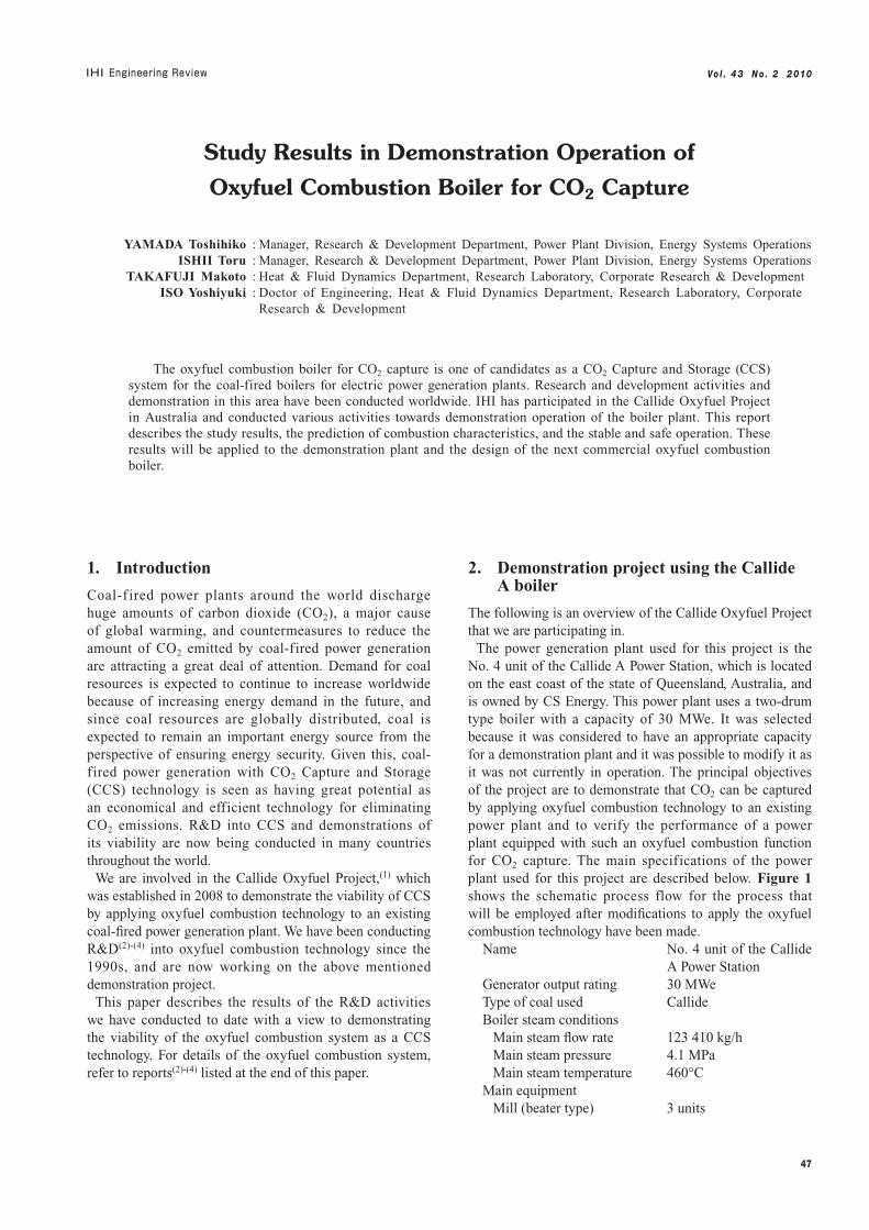
The power generation plant used for this project is the No. 4 unit of the Callide A Power Station, which is located on the east coast of the state of Queensland, Australia, and is owned by CS Energy. This power plant uses a two-drum type boiler with a capacity of 30 MWe. It was selected because it was considered to have an appropriate capacity for a demonstration plant and it was possible to modify it as it was not currently in operation. The principal objectives of the project are to demonstrate that CO2 can be captured by applying oxyfuel combustion technology to an existing power plant and to verify the performance of a power plant equipped with such an oxyfuel combustion function for CO2 capture. The main specifications of the power plant used for this project are described below. Figure 1 shows the schematic process flow for the process that will be employed after modifications to apply the oxyfuel combustion technology have been made.
Name No. 4 unit of the Callide A Power Station
Generator output rating 30 MWeType of coal used CallideBoiler steam conditions Main steam flow rate 123 410 kg/h Main steam pressure 4.1 MPa Main steam temperature 460°CMain equipment Mill (beater type) 3 units
Study Results in Demonstration Operation of
Oxyfuel Combustion Boiler for CO2 Capture
YAMADA Toshihiko : Manager, Research & Development Department, Power Plant Division, Energy Systems Operations ISHII Toru : Manager, Research & Development Department, Power Plant Division, Energy Systems Operations TAKAFUJI Makoto : Heat & Fluid Dynamics Department, Research Laboratory, Corporate Research & Development ISO Yoshiyuki : Doctor of Engineering, Heat & Fluid Dynamics Department, Research Laboratory, Corporate Research & Development
The oxyfuel combustion boiler for CO2 capture is one of candidates as a CO2 Capture and Storage (CCS) system for the coal-fired boilers for electric power generation plants. Research and development activities and demonstration in this area have been conducted worldwide. IHI has participated in the Callide Oxyfuel Project in Australia and conducted various activities towards demonstration operation of the boiler plant. This report describes the study results, the prediction of combustion characteristics, and the stable and safe operation. These results will be applied to the demonstration plant and the design of the next commercial oxyfuel combustion boiler.
48
Vo l . 4 3 N o . 2 2 010
Burner (front side) 6 units Forced draft fan/induced draft fan 2 units of each Tubular-type heat exchanger 1 unit Fabric filter 1 unit
In this project, modifications will be made to install an oxygen production system and apply oxyfuel combustion technology to the boiler system, and also to install a liquef ied CO2 capture system that employs exhaust gas compression and cooling. Preparations to start demonstrations of its operation in 2011 are proceeding smoothly.
Although a number of other projects(5) to demonstrate the oxyfuel combustion system have been implemented or are being implemented in countries around the world, the Callide Oxyfuel Project is unique in that :
(1) Instead of just using combustion test facilities, we will be modifying an existing power plant that was once used for commercial operations in order to equip it with oxyfuel combustion technology, which will be the first time such an attempt has ever been made anywhere in the world.
(2) Multi-burners and pulverizers will be integrated into the oxyfuel boiler system so that the equipment configuration and process flow are likely to be the same as those of the commercial power plants of the future.
3. Expected combustion and heat transfer characteristics of the demonstration unit
So far, we have conducted tests to validate the capture of CO2
(3) from the exhaust gas emitted by oxyfuel combustion and ascertain the basic combustion characteristics(2), (4)
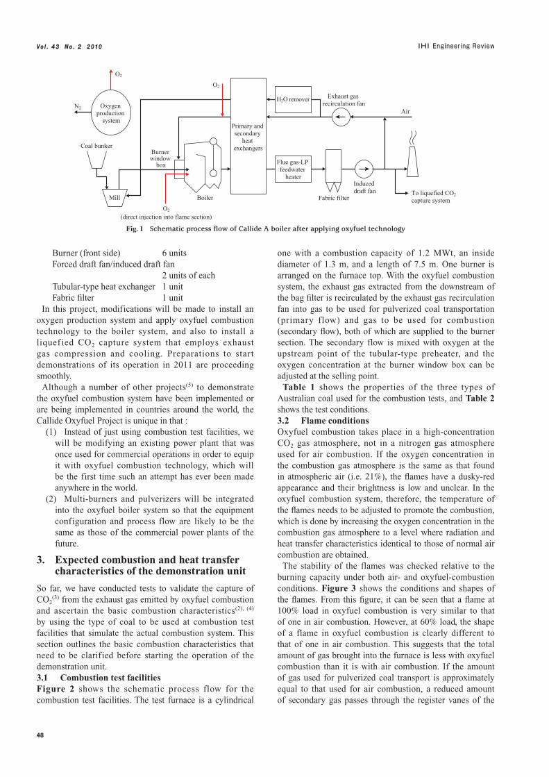
by using the type of coal to be used at combustion test facilities that simulate the actual combustion system. This section outlines the basic combustion characteristics that need to be clarified before starting the operation of the demonstration unit.3.1 Combustion test facilitiesFigure 2 shows the schematic process flow for the combustion test facilities. The test furnace is a cylindrical
one with a combustion capacity of 1.2 MWt, an inside diameter of 1.3 m, and a length of 7.5 m. One burner is arranged on the furnace top. With the oxyfuel combustion system, the exhaust gas extracted from the downstream of the bag filter is recirculated by the exhaust gas recirculation fan into gas to be used for pulverized coal transportation (primary flow) and gas to be used for combustion (secondary flow), both of which are supplied to the burner section. The secondary flow is mixed with oxygen at the upstream point of the tubular-type preheater, and the oxygen concentration at the burner window box can be adjusted at the selling point.
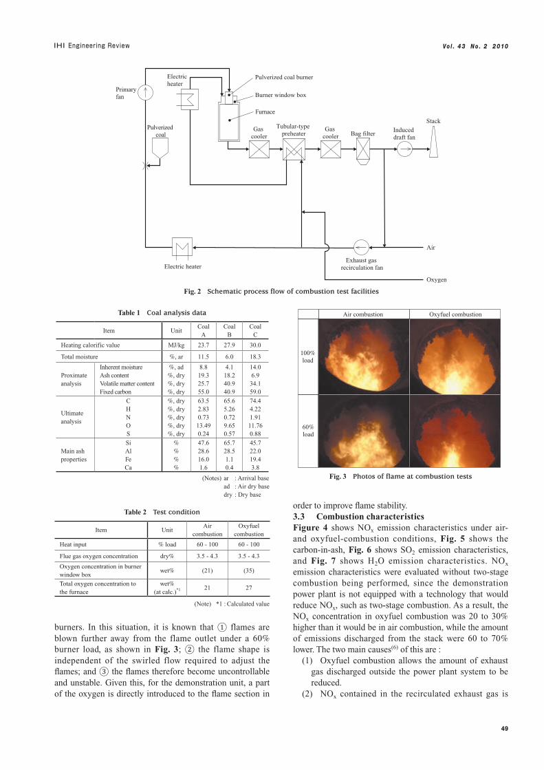
Table 1 shows the properties of the three types of Australian coal used for the combustion tests, and Table 2 shows the test conditions.3.2 Flame conditionsOxyfuel combustion takes place in a high-concentration CO2 gas atmosphere, not in a nitrogen gas atmosphere used for air combustion. If the oxygen concentration in the combustion gas atmosphere is the same as that found in atmospheric air (i.e. 21%), the flames have a dusky-red appearance and their brightness is low and unclear. In the oxyfuel combustion system, therefore, the temperature of the flames needs to be adjusted to promote the combustion, which is done by increasing the oxygen concentration in the combustion gas atmosphere to a level where radiation and heat transfer characteristics identical to those of normal air combustion are obtained.
The stability of the flames was checked relative to the burning capacity under both air- and oxyfuel-combustion conditions. Figure 3 shows the conditions and shapes of the flames. From this figure, it can be seen that a flame at 100% load in oxyfuel combustion is very similar to that of one in air combustion. However, at 60% load, the shape of a flame in oxyfuel combustion is clearly different to that of one in air combustion. This suggests that the total amount of gas brought into the furnace is less with oxyfuel combustion than it is with air combustion. If the amount of gas used for pulverized coal transport is approximately equal to that used for air combustion, a reduced amount of secondary gas passes through the register vanes of the
Oxygen production
system
Coal bunker
Mill Boiler
Burner window
box
N2
O2
O2
To liquefied CO2
capture systemO2
(direct injection into flame section)
Flue gas-LP feedwater
heater
Fabric filter
Induced draft fan
Exhaust gas recirculation fan
Air
H2O remover
Primary and secondary
heat exchangers
Fig. 1 Schematic process flow of Callide A boiler after applying oxyfuel technology
49
Vo l . 4 3 N o . 2 2 010
burners. In this situation, it is known that ① flames are blown further away from the flame outlet under a 60% burner load, as shown in Fig. 3; ② the flame shape is independent of the swirled flow required to adjust the flames; and ③ the flames therefore become uncontrollable and unstable. Given this, for the demonstration unit, a part of the oxygen is directly introduced to the flame section in
order to improve flame stability.3.3 Combustion characteristicsFigure 4 shows NOx emission characteristics under air- and oxyfuel-combustion conditions, Fig. 5 shows the carbon-in-ash, Fig. 6 shows SO2 emission characteristics, and Fig. 7 shows H2O emission characteristics. NOx emission characteristics were evaluated without two-stage combustion being performed, since the demonstration power plant is not equipped with a technology that would reduce NOx, such as two-stage combustion. As a result, the NOx concentration in oxyfuel combustion was 20 to 30% higher than it would be in air combustion, while the amount of emissions discharged from the stack were 60 to 70% lower. The two main causes(6) of this are :
(1) Oxyfuel combustion allows the amount of exhaust gas discharged outside the power plant system to be reduced.
(2) NOx contained in the recirculated exhaust gas is
Gas cooler
Gas cooler
Primary fan
Pulverized coal
Electric heater
Tubular-type preheater Bag filter
Electric heater
Pulverized coal burner
Burner window box
Furnace
Induced draft fan
Air
Exhaust gas recirculation fan
Oxygen
Stack
Fig. 2 Schematic process flow of combustion test facilities
Table 1 Coal analysis data
Item UnitCoal
ACoal
BCoal
C
Heating calorific value MJ/kg 23.7 27.9 30.0
Total moisture %, ar 11.5 6.0 18.3
Proximate analysis
Inherent moistureAsh contentVolatile matter contentFixed carbon
%, ad%, dry%, dry%, dry
8.819.325.755.0
4.118.240.940.9
14.06.934.159.0
Ultimate analysis
CHNOS
%, dry%, dry%, dry%, dry%, dry
63.52.830.7313.490.24
65.65.260.729.650.57
74.44.221.9111.760.88
Main ash properties
SiAlFeCa
%%%%
47.628.616.01.6
65.728.51.10.4
45.722.019.43.8
(Notes) ar : Arrival base ad : Air dry base dry : Dry base
Table 2 Test condition
Item UnitAir
combustionOxyfuel
combustion
Heat input % load 60 - 100 60 - 100
Flue gas oxygen concentration dry% 3.5 - 4.3 3.5 - 4.3
Oxygen concentration in burner window box
wet% (21) (35)
Total oxygen concentration to the furnace
wet%(at calc.)*1 21 27
(Note) *1 : Calculated value
Air combustion Oxyfuel combustion
100% load
60% load
Fig. 3 Photos of flame at combustion tests

50
Vo l . 4 3 N o . 2 2 010
0
20
40
60
80
100
0 20 40 60 80 100Carbon-in-ash with air combustion*1 (–)
Car
bon-
in-a
sh w
ith
oxyg
en c
ombu
stio
n*1 (
–)
(Note) *1 : Relative values
: Coal A: Coal B: Coal C
Fig. 5 Carbon in ash
0
20
40
60
80
100
0.0 0.5 1.0 1.5 2.0 2.5
N content in fuel (dry%)
NO
x con
cent
rati
on*1
(–)
: Coal A/oxyfuel : Coal B/oxyfuel : Coal C/oxyfuel
: Coal A/air : Coal B/air : Coal C/air
(a) N content in fuel and NOx concentration
Amount of NOx emissions with air combustion*1 (–)
(Note) *1 : Relative values
Am
ount
of
NO
x em
issi
ons
wit
h ox
yfue
l com
bust
ion*
1 (
–)
(b) Amount of NOx emissions with air combustion compared to that with oxyfuel combustion
0
20
40
60
80
100
0 20 40 60 80 100
: Coal A: Coal B: Coal C
Fig. 4 NOx emission characteristics
0
20
40
60
80
100
0.0 0.2 0.4 0.6 0.8 1.0
S content in fuel (dry%)
SO
2 co
ncen
trat
ion*1
(–)
0
20
40
60
80
100
0 20 40 60 80 100
Amount of SO2 emissions with air combustion*1 (–)
Am
ount
of
SO
2 em
issi
ons
wit
h ox
yfue
l com
bust
ion*
1 (
–)
(Note) *1 : Relative values
(b) Amount of SO2 emissions with air combustion compared to that with oxyfuel combustion
(a) S content in fuel and SO2 concentration
: Coal A: Coal B: Coal C
: Coal A/oxyfuel : Coal B/oxyfuel : Coal C/oxyfuel
: Coal A/air : Coal B/air : Coal C/air
Fig. 6 SO2 emission characteristics
0
20
40
60
80
100
0 20 40 60 80 100
H2O concentration with air combustion*1 (–)
H2O
con
cent
rati
on w
ith
oxyf
uel c
ombu
stio
n*1 (
–)
(Note) *1 : Relative values
: Coal A: Coal B: Coal C
Fig. 7 H2O emission characteristics
51
Vo l . 4 3 N o . 2 2 010
decomposed at the flame section.With oxyfuel combustion, the amount of carbon-in-ash
left unburned tends to be less. It is thought that this can be attributed to the following two factors :
(1) The residence time of the high-temperature region in the furnace is longer in oxyfuel combustion so there is less exhaust gas if the same combustion furnace is used.
(2) Localized areas of high oxygen concentration result in improved combustion conditions.
Figure 6 shows SO2 emission characteristics in relation to the types of coal used. Although the SO2 concentration in the exhaust gas is about 2.5 times higher with oxyfuel combustion, the amount of exhaust gas discharged outside the power plant system is about 30% lower. This is because the sulfur content moves easily into the ash due to the higher SO2 content in the exhaust gas with oxyfuel combustion.(7)
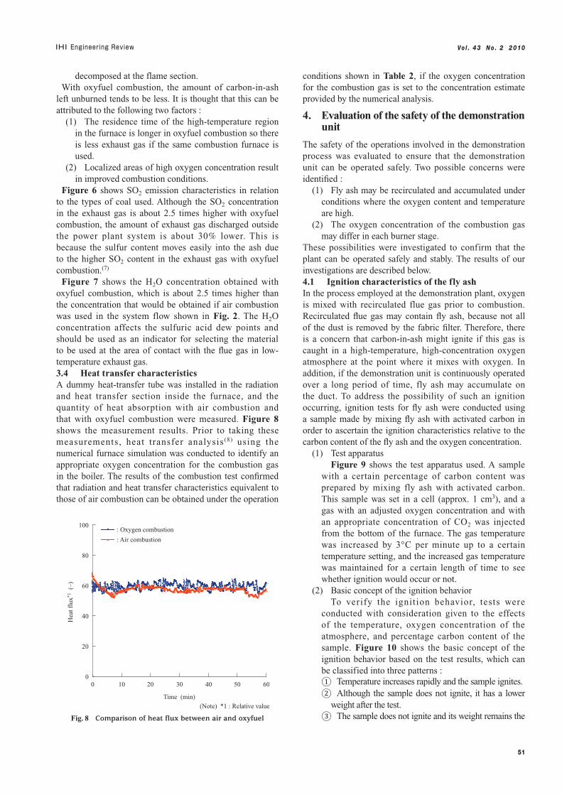
Figure 7 shows the H2O concentration obtained with oxyfuel combustion, which is about 2.5 times higher than the concentration that would be obtained if air combustion was used in the system flow shown in Fig. 2. The H2O concentration affects the sulfuric acid dew points and should be used as an indicator for selecting the material to be used at the area of contact with the flue gas in low-temperature exhaust gas.3.4 Heat transfer characteristicsA dummy heat-transfer tube was installed in the radiation and heat transfer section inside the furnace, and the quantity of heat absorption with air combustion and that with oxyfuel combustion were measured. Figure 8 shows the measurement results. Prior to taking these measurements, heat transfer analysis (8) using the numerical furnace simulation was conducted to identify an appropriate oxygen concentration for the combustion gas in the boiler. The results of the combustion test confirmed that radiation and heat transfer characteristics equivalent to those of air combustion can be obtained under the operation
conditions shown in Table 2, if the oxygen concentration for the combustion gas is set to the concentration estimate provided by the numerical analysis.
4. Evaluation of the safety of the demonstration unit
The safety of the operations involved in the demonstration process was evaluated to ensure that the demonstration unit can be operated safely. Two possible concerns were identified :
(1) Fly ash may be recirculated and accumulated under conditions where the oxygen content and temperature are high.
(2) The oxygen concentration of the combustion gas may differ in each burner stage.
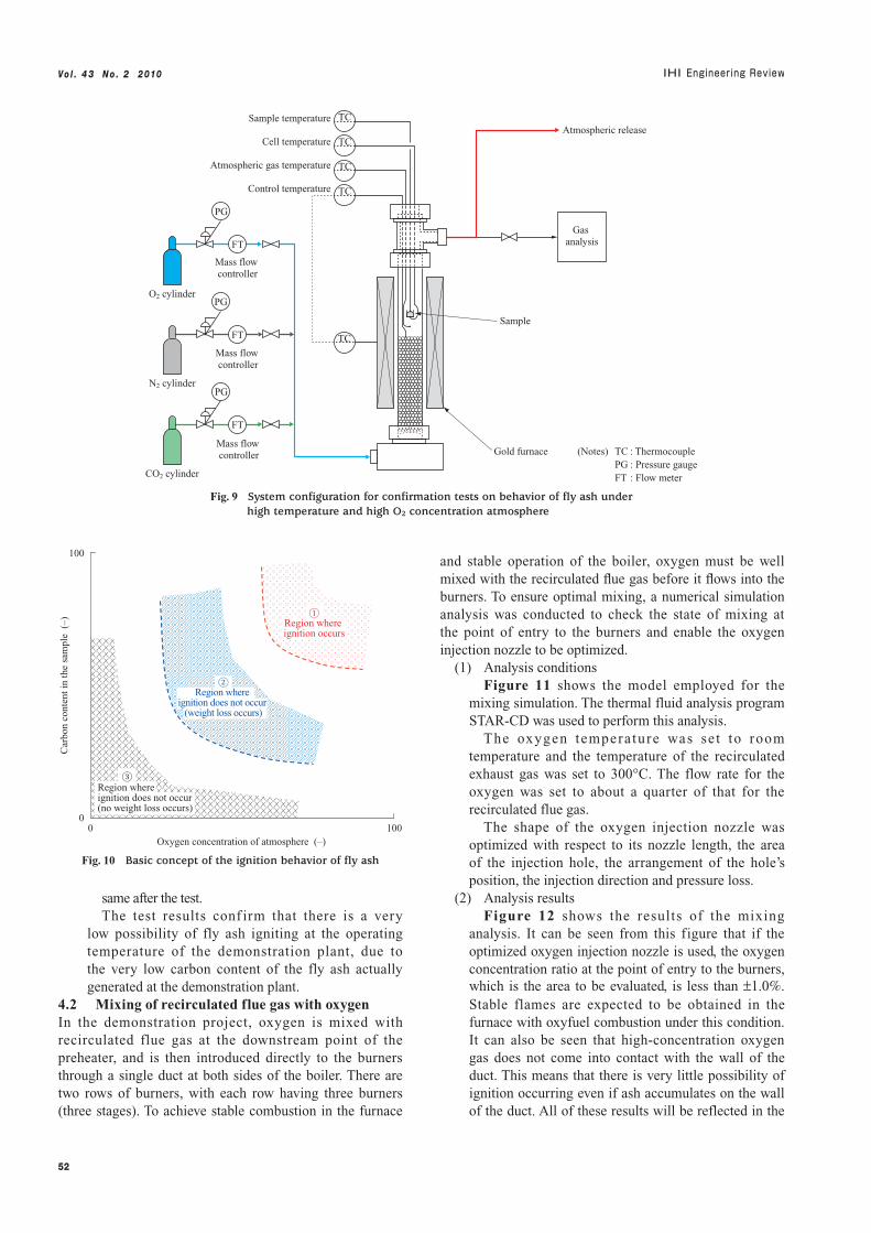
These possibilities were investigated to confirm that the plant can be operated safely and stably. The results of our investigations are described below.4.1 Ignition characteristics of the fly ashIn the process employed at the demonstration plant, oxygen is mixed with recirculated flue gas prior to combustion. Recirculated flue gas may contain fly ash, because not all of the dust is removed by the fabric filter. Therefore, there is a concern that carbon-in-ash might ignite if this gas is caught in a high-temperature, high-concentration oxygen atmosphere at the point where it mixes with oxygen. In addition, if the demonstration unit is continuously operated over a long period of time, fly ash may accumulate on the duct. To address the possibility of such an ignition occurring, ignition tests for fly ash were conducted using a sample made by mixing fly ash with activated carbon in order to ascertain the ignition characteristics relative to the carbon content of the fly ash and the oxygen concentration.
(1) Test apparatusFigure 9 shows the test apparatus used. A sample
with a certain percentage of carbon content was prepared by mixing fly ash with activated carbon. This sample was set in a cell (approx. 1 cm3), and a gas with an adjusted oxygen concentration and with an appropriate concentration of CO2 was injected from the bottom of the furnace. The gas temperature was increased by 3°C per minute up to a certain temperature setting, and the increased gas temperature was maintained for a certain length of time to see whether ignition would occur or not.
(2) Basic concept of the ignition behaviorTo verify the ignition behavior, tests were
conducted with consideration given to the effects of the temperature, oxygen concentration of the atmosphere, and percentage carbon content of the sample. Figure 10 shows the basic concept of the ignition behavior based on the test results, which can be classified into three patterns : ① Temperature increases rapidly and the sample ignites.② Although the sample does not ignite, it has a lower
weight after the test.③ The sample does not ignite and its weight remains the
0
20
40
60
80
100
0 10 20 30 40 50 60
Time (min)
Hea
t flu
x*1 (
–)
: Oxygen combustion
: Air combustion
(Note) *1 : Relative value
Fig. 8 Comparison of heat flux between air and oxyfuel
52
Vo l . 4 3 N o . 2 2 010
same after the test.The test results conf irm that there is a very
low possibility of fly ash igniting at the operating temperature of the demonstration plant, due to the very low carbon content of the fly ash actually generated at the demonstration plant.
4.2 Mixing of recirculated flue gas with oxygenIn the demonstration project, oxygen is mixed with recirculated flue gas at the downstream point of the preheater, and is then introduced directly to the burners through a single duct at both sides of the boiler. There are two rows of burners, with each row having three burners (three stages). To achieve stable combustion in the furnace
and stable operation of the boiler, oxygen must be well mixed with the recirculated flue gas before it flows into the burners. To ensure optimal mixing, a numerical simulation analysis was conducted to check the state of mixing at the point of entry to the burners and enable the oxygen injection nozzle to be optimized.
(1) Analysis conditionsFigure 11 shows the model employed for the
mixing simulation. The thermal fluid analysis program STAR-CD was used to perform this analysis.
The oxygen tempera ture was se t to room temperature and the temperature of the recirculated exhaust gas was set to 300°C. The flow rate for the oxygen was set to about a quarter of that for the recirculated flue gas.
The shape of the oxygen injection nozzle was optimized with respect to its nozzle length, the area of the injection hole, the arrangement of the hole’s position, the injection direction and pressure loss.
(2) Analysis resultsFigure 12 shows the results of the mixing
analysis. It can be seen from this figure that if the optimized oxygen injection nozzle is used, the oxygen concentration ratio at the point of entry to the burners, which is the area to be evaluated, is less than ±1.0%. Stable flames are expected to be obtained in the furnace with oxyfuel combustion under this condition. It can also be seen that high-concentration oxygen gas does not come into contact with the wall of the duct. This means that there is very little possibility of ignition occurring even if ash accumulates on the wall of the duct. All of these results will be reflected in the
0
100
0 100Oxygen concentration of atmosphere (–)
Car
bon
cont
ent i
n th
e sa
mpl
e (
–)
①Region where ignition occurs
②Region where
ignition does not occur (weight loss occurs)
③Region where ignition does not occur (no weight loss occurs)
Fig. 10 Basic concept of the ignition behavior of fly ash
Mass flow controller
Mass flow controller
Mass flow controller
O2 cylinder
N2 cylinder
CO2 cylinder
Gold furnace
Sample
Gas analysis
Atmospheric release
PG
TCSample temperature
Cell temperature
Atmospheric gas temperature
Control temperature
TC
TC
TC
TC
FT
PG
FT
PG
FT
(Notes) TC : Thermocouple PG : Pressure gauge FT : Flow meter
Fig. 9 System configuration for confirmation tests on behavior of fly ash under high temperature and high O2 concentration atmosphere

53
Vo l . 4 3 N o . 2 2 010
design of the demonstration plant and confirmed when operation of the demonstration unit is set to start.
5. Conclusion
This paper presents some of the results obtained from the combustion test, ignition test and mixing simulation that need to be examined based on prior knowledge and information on oxyfuel combustion before they can be applied to the demonstration project. To ensure that the demonstration plant will be operated properly and to
make the oxyfuel combustion boiler for CO2 capture commercially viable, we will further promote R&D in this fi eld and continue to accumulate data and know-how while endeavoring to realize a safe and stable oxyfuel combustion power plant for CO2 capture as early as possible.
— Acknowledgments —
We were able to conduct the surveys and studies described in this paper thanks to the cooperation and support rendered by the Agency for Natural Resources and Energy, the
Burner section
Area where recirculated exhaust gas mixes with oxygen
Oxygen concentration ratio (–)
Oxygen concentration ratio (–)
(b) Area to be evaluated
(a) Overview of the duct (b) Area to be evaluated
0.50.40.30.20.10.0
0.350.340.330.320.310.300.290.280.270.260.25
Fig. 12 Mixing simulation results
Burner window box Burner section
Mixture gas of recirculated flue gas and oxygen
Duct
Area where concentration distribution is evaluated
Oxygen injection nozzle
Oxygen
Recirculated flue gas
Plate
Tubular-type heat exchanger
Fig. 11 Mixing simulation model

54
Vo l . 4 3 N o . 2 2 010
Ministry of Economy, Trade and Industry, the New Energy and Industrial Technology Development Organization, CS Energy, Electric Power Development Co., Ltd., MITSUI & CO., LTD., and many individuals from Japan and Australia. We would like to offer them our sincere thanks.
REFERENCES
(1) Chris Spero : Callide Oxyfuel Project - Status & Development - Proc. 1st Oxyfuel Combustion Conference (2009. 9)
(2) S. Takano, T. Kiga, Y. Endo, S. Miyamae and K. Suzuki : CO2 Recovery from PCF Power Plant with O2/CO2 Combustion Process IHI Engineering Review Vol. 28 No. 4 (1995. 10) pp. 160-164
(3) T. Yamada, T. Kiga, N. Fujita and T. Inoue : O2/Recycled Flue Gas Combustion-Applied Pulverized Coal Fired Power Plant for CO2 Recovery IHI Engineering Review Vol. 32 No. 3 (1999. 7) pp. 98-103
(4) T. Suda, Y. Oda, K. Masuko and S. Miyamae : Fundamental Study of Coal Combustion Mechanism in O2/Recycled Flue Gas Combustion Process Ishikawajima-Harima Engineering Review Vol. 40 No. 3 (2000. 5) pp. 119-123
(5) Terry Wall : Coal Based Oxy-fuel Technology - Progress to Deployment - Proc. 1st Oxyfuel Combustion Conference (2009. 9)
(6) K. Okazaki and T. Ando : NOx Reduction Mechanism in Coal Combustion with Recycled CO2 Energy Vol. 22 No. 2/3 (1997) pp. 207-215
(7) Hao Liu, S. Katagiri and K. Okazaki : Drastic SOx Removal and Influences of Various Factors in O2/CO2 Pulverized Coal Combustion System Energy & Fuels 15 (2001) pp. 403-412
(8) T. Yamada, N. Misawa and T. Kiga : CO2 Capture using Oxyfuel Combustion Technology at Coal Fired Power Plant - Callide Oxyfuel Project - Journal of the Gas Turbine Society of Japan Vol. 37 No. 2 (2009. 3) pp. 67-71