study report sr199 effective passive roof venting using
TRANSCRIPT

STUDY REPORT No. 199 (2008)
Effective Passive Roof Venting using Roof Panels in
the Event of a Fire Part 3: Summary
A.P. Robbins and C. A. Wade
The work reported here was jointly funded by Building Research Levy.
© BRANZ 2008 ISSN: 1178-4938

i
Preface This report was prepared as a result of a preliminary modelling and experimental investigation of materials, general designs and test methods for passive roof venting during a fire event to determine appropriate standard test methods, performance criteria and any other design requirements for regulation. Acknowledgments This work was funded by the Building Research Levy. Note This report is intended for regulatory authorities, researchers, manufacturers, fire engineers and designers.

ii
Effective Passive Roof Venting using Roof Panels in the Event of a Fire Part 3: Summary BRANZ Study Report SR 199 A. P. Robbins and C. A. Wade Reference Robbins A.P. and Wade C.A. 2008. ‘Effective Passive Roof Venting using Roof Panels in the Event of Fire. Part 3: Summary’. BRANZ Study Report SR 199. BRANZ Ltd, Judgeford, New Zealand.
Abstract This report comprises Part 3 of a three-part series on an investigation of passive buoyancy-driven roof fire vents in large floor area single storey buildings. The report summarises the conclusions from the modelling and experimental parts of the investigation. The primary objective of this report is to present recommendations for the practice of using (plastics) roofing panels that melt or degrade at elevated temperatures for the secondary purpose of venting smoke and heat under fire conditions.

iii
Contents Page 1. Introduction ........................................................................................................................................................................ 1
1.1 Motivation .................................................................................................................................................................. 1 1.2 Objective .................................................................................................................................................................... 2 1.3 Scope ........................................................................................................................................................................... 2
2. Summary of Current C/AS1 Regulatory Requirements ............................................................................. 3 2.1 Discussion of the Current Paragraph 4.2.4............................................................................................ 3
3. Summary of the Intent of ‘Effective Fire Venting’ ......................................................................................... 4 3.1 Performance Criteria for Fire Venting ...................................................................................................... 4
4. Summary of Preliminary Experiment Investigation ................................................................................... 5 4.1 Conclusions from the Experimental Investigation ........................................................................... 7
5. Summary of Modelling Investigation ................................................................................................................. 9 5.1 Conclusions from the Modelling Investigation ................................................................................ 14
6. General Conclusions .................................................................................................................................................. 16 7. Discussion of Limitations of Fire Venting ........................................................................................................ 17 8. Recommendations for Passive Fire Venting Practices Utilising Roofing Panels .................. 18
8.1 Recommendations for Future Work ....................................................................................................... 20 9. References ....................................................................................................................................................................... 21
9.1 Regulations and Standards .......................................................................................................................... 21 9.2 General References ..........................................................................................................................................22

iv
Figures Page Figure 1: Test apparatus. ....................................................................................................... 6 Figure 2: Example of a test specimen before being placed on the test apparatus,
showing (a) before the roof sheeting is attached and (b) after roof sheeting is attached. ......................................................................................................................... 7
Figure 3: Schematic of the generic warehouse showing the general placement of the panels to be used as roof vents assumed in modelling when applying a CFD approach. (N.B. Not to scale.).......................................................................................... 9
Figure 4: Examples of the base case virtual heat detector temperature results at 1,000 s from ignition for (a) Scenario 1, (b) Scenario 2, (c) Scenario 3, and (d) Scenario 4. .................................................................................................................... 11
Figure 5: Examples of the base case incident radiant intensity (kW/m²) results at 2 m above floor at 1,000 s from ignition for (a) Scenario 1, (b) Scenario 2, (c) Scenario 3, and (d) Scenario 4. ..................................................................................... 12
Figure 6: Examples of the base case gas temperatures (°C) results at 5.5 m above floor at 1,000 s from ignition for (a) Scenario 1, (b) Scenario 2, (c) Scenario 3, and (d) Scenario 4. ........................................................................................................ 13
v
Acronyms C/AS1 Fire Safety Compliance Documents (C Clauses), Acceptable Solution FHC Fire Hazard Category FLED Fire Load Effective Design NZ New Zealand NZBC New Zealand Building Code NZFS New Zealand Fire Service

1
1. INTRODUCTION In large area single storey buildings, “…although a fire may involve only a relatively small area of the floor, the smoke and hot gases will quickly fill the building and experience has shown that the fire can be completely concealed before the arrival of the fire brigade.” (Thomas et al 1963) Fire-fighting is then difficult and dangerous, since the fire must be located within the building and the smoke and heat conditions may be sufficiently severe to limit the fire brigade to conducting an external fire attack. External attacks are ineffective as fire hose streams rarely reach the seat of the fire for extinguishment. This only results in greater water damage and potential for contaminated fire-fighting water run-off. The temperatures of the hot layer trapped beneath the roof may also be sufficiently high to cause softening or failure of unprotected roof construction or ignite flammable roof materials.
A passive roof fire venting system relying on buoyancy of the hot fire products to provide the driving force for removal of the hot gases has advantages: simplicity, effectiveness in a wide range of fire conditions and independence from any available power supply that may be disrupted during a fire. For example, the rate of removal of hot gases is largely dependent upon the depth and temperature of smoke. Therefore if a fire grows larger than the assumed design fire size used to calculate the vent area, the deeper and hotter smoke layer would lead to an increased flow rate of smoke through the vent (i.e. venting of the hot products would still occur, but the desired level of ‘effectiveness’ may not be achieved). Thus a passive fire venting system has an element of self-compensation (Morgan and Gardner 1990). However, as with all ‘reliable’ and “effective” systems, the reliability and effectiveness must be determined through demonstration of design.
1.1 Motivation The motivation for this series of reports includes the following:
The New Zealand Building Act (2004) does not require building owners to consider owner property protection and consequently many industrial buildings have been constructed in the expectation that insurers will cover the fire loss.
Fires in large industrial buildings can be very difficult for the fire service to control and extinguish. To assist fire service operations, the Building Code Compliance Document C/AS1 (2001, with Amendments up to October 2005) places a limit on the maximum compartment floor area in unsprinklered buildings (typically 1500 m²). This is designed to limit the total fire load in a firecell to less than 2 million MJ.
No subdivision of the building is required if at least 15% of the roof area (distributed evenly throughout the firecell) is designed for effective fire venting. Subdividing large industrial buildings is often undesirable for functional reasons, and therefore the roof venting option is a popular one.
No detailed specification or standard is currently referenced in the compliance document to ensure that fire venting is ‘effective’. The current performance and effectiveness of these systems is therefore not well understood.
The compliance document requires that (plastics) roof panels for fire venting to be evenly distributed over the area of the roof. An even distribution across the roof area is appropriate for flat or very shallow roofs, but venting in steep roofs would be more effective if located near the apex.

2
Detailed guidance on how to assess the effectiveness of roof venting systems leading to appropriate specifications for them is needed by designers and building consent authorities. Mechanically operated smoke and heat venting systems for fire are established technology overseas and various codes and standards do exist that may be suitable for use in New Zealand. Passive systems such as dedicated units utilising drop out panels are less common and design guidance is not currently available.
1.2 Objective The objectives of this report are to:
1. Summarise the conclusions of the preliminary modelling and the reduced-scale experiments performed to investigate the required general material properties and potential standard test methods.
2. Present recommendations for the design and evaluation of passive plastics roof fire venting systems based on the results of this investigation.
1.3 Scope The scope of this series of reports is limited to researching the appropriateness of buoyancy-driven roof fire venting that relies on the passive failure due to melting or degradation and the subsequent development of openings formed in the plastics roofing materials creating an opening for the removal of hot combustion gases from the building. Other important roofing related criteria, such as durability, rain leakage, etc. are considered to be beyond the scope. Active or mechanically operated venting systems are also outside the scope of this project.
The assessment of specific materials and proprietary systems is outside the scope of this project, since the roof construction method, use of specific engineering additives to the base material and the geometry (e.g. thickness) of the panel contribute to the overall performance of the system.

3
2. SUMMARY OF CURRENT C/AS1 REGULATORY REQUIREMENTS Unsprinklered firecells to which an S Rating applies are required by New Zealand Compliance Document for the C Clauses C/AS1 (2001) (Paragraph 4.2.3) to be limited in floor area with the maximum area depending on the Fire Hazard Category. However Paragraph 4.2.4 permits an exception as follows:
“4.2.4 In an unsprinklered single floor building where the building elements supporting the roof are not fire rated, the firecell floor area may be unlimited provided that no less than 15% of the roof area (distributed evenly throughout the firecell) is designed for effective fire venting.”
The benefit in this paragraph is that “the firecell floor area may be unlimited”.
The requirements to gain this benefit are:
1. single floor building
2. building elements supporting the roof are not fire rated
3. the roof area is designed for effective fire venting
4. no less than 15% of the roof area (distributed evenly throughout the firecell) is designed for effective fire venting
2.1 Discussion of the Current Paragraph 4.2.4 The current requirement of C/AS1 (2001) for effective fire venting is discussed in more detail in Part 1 of this series of reports (Robbins & Wade 2008a)
From the discussion in Part 1 (Robbins & Wade 2008a) the logic follows that the intent of fire venting as described in P.4.2.4 is to assist fire-fighting operations and the protection of other property. Fire venting may achieve this by delaying the onset of smoke logging and improving thermal conditions within the compartment to assist fire-fighter operations (that would occur at a later stage than the equivalent time of sprinkler activation) and, in combination with partial roof collapse, provide a safety factor by reducing the fire intensity within the compartment during complete burnout. However the capacity for reducing the thermal conditions in the compartment would not be equal for a sprinkler system as for a fire venting system. In addition there are other advantages of a sprinkler system that cannot be matched by fire venting, such as owner property and contents protection, assisting with occupant escape in case of rapid fire growth, etc.
In general, fire venting may assist fire-fighting operations by:
� removing the hot fire products – reducing radiation from the hot layer to fire-fighters
� removing hot smoke – allowing the seat of the fire to be more easily located
� reducing the fire intensity – reducing the thermal load on fire-fighters
� delaying flashover of the compartment – allowing more time for fire-fighting operations to be applied
In general, fire venting may assist in limiting the thermal load within the compartment by:
� removing the hot fire products – reducing radiation from the hot layer to other combustibles within the firecell, which will assist in delaying the spread of fire by radiation and flashover of the compartment.

4
It is imperative that the intent of ‘effective fire venting’ is defined. Appropriate quantitative performance criteria are required to assess effectiveness of fire venting designs. For example, values for such performance parameters related to time, visibility, radiation flux and gas temperatures may be appropriate for assessing the level of assistance for fire-fighting purposes. Therefore definitions and performance criteria used for this research are discussed in the following section.
3. SUMMARY OF THE INTENT OF ‘EFFECTIVE FIRE VENTING’ Following on from the above discussion of the current C/AS1 (2001) requirements, the intent of fire venting is assumed, for the purposes of this research, to be defined as:
Fire venting is a system designed for the removal of hot fire gases during the initial growth phase of the fire in order to reduce the hot smoke logging and thermal loading of the compartment to facilitate fire-fighting operations (in terms of rescue, if necessary, and protection of other property).
That is fire venting contributes directly to the New Zealand Building Code objective to facilitate fire-fighting operations and indirectly to the objective of protection of other property.
Fire venting may operate within or after the maximum permitted escape times have been surpassed coincidentally, as fire venting design is not specifically related to occupant escape time. Furthermore passive fire venting is not interlinked with smoke or heat detection that would be linked to alerting occupants and is thus potentially related to facilitation of escape. Therefore fire venting does not contribute to life safety of the initial occupants of a building during the early stages of fire development.
A more detailed discussion of the intent of fire venting and the discussion leading to the selection of performance criteria for this investigation is presented in Part 1, Section 3, of this series of reports (Robbins & Wade 2008a).
3.1 Performance Criteria for Fire Venting For this study the performance criteria for fire venting is defined as (Robbins & Wade 2008a, Section 3):
At the time first fire suppression activities begin, the conditions within the building are:
a maximum radiation of 4.5 kW/m² at 1.5 m above the floor,
a minimum height to the bottom of the smoke layer of 2.0 m, and
a maximum gas temperature of 573 K at ceiling.

5
4. SUMMARY OF PRELIMINARY EXPERIMENT INVESTIGATION A test method (Robbins & Wade 2008b) was developed based on modifying an existing standard test method for dedicated buoyancy driven roof fire vents, AS 2428.3 (2004). The general concept of the test method is to subject a test specimen (2.7 x 1.4 m), which represents a section of roof, including a potential venting panel, to hot combustion gases on a reduced scale and to observe and record the venting characteristics.
The test specimen is shielded from direct flame impingement and radiation by a non-combustible shield. Flames are not to extend beyond the lower level of the smoke curtains. This is important since:
1. a fire vent is unlikely to be positioned directly over a fire and therefore have reduced incident radiation to assist in the formation of any potential openings, and
2. flame impingement on the roof during the early stages of a fire is an unlikely scenario.
The temperature profile below the vent is recorded and used to control the test. A grid of thermocouples is located 100 mm below the top edge of the smoke curtain, where the test specimen is attached.
Two rates of temperature increase were considered: a rapid heating rate (200±20°C per minute) and a slow heating rate (10±2°C per minute) from ambient to 300°C.
Twenty tests were performed to gather data and experience with the test method and to develop and improve the method.
Figure 1 shows views of the test apparatus. Figure 2 shows an example of a test specimen before being placed on top of the test apparatus. Details of the experimental setup and tests performed are included in Part 2, Section 3 of this series of reports (Robbins & Wade 2008b).

6
(a)
(b)
Figure 1: Test apparatus.
Mesh locating thermocouples
Smoke curtain
Thermocouple wire
Layers of shielding baffles
Flange for attaching test specimen

7
(a) (b)
Figure 2: Example of a test specimen before being placed on the test apparatus, showing (a) before the roof sheeting is attached and (b) after roof sheeting is attached.
4.1 Conclusions from the Experimental Investigation This section is a summary of the conclusions drawn from the results of the experimental investigation (Robbins & Wade 2008b, Sections 6 & 7).
Several important aspects highlighted in the results of this study include:
1. It is not recommended to subject roof sheeting for fire venting characteristics to the current test methods or criteria as currently used for dedicated fire vents, such as AS 2428.3 (2004) or BS 7346 Part 1 (1990). The reasons for this include:
The entire panel is highly unlikely to form complete openings and openings are not formed at the same time, therefore an arbitrary area would have to be chosen for the minimum acceptable vent area as part of the performance criteria.
It is difficult to ascertain the time at which an opening forms in the panel based on how big an opening has to be to be considered effective.
There are better ways of assessing the time when openings form based on quantitative recorded parameters rather than subjective observations.
Driving the test to fit a pre-determined temperature time curve masks the temperature benefits of any openings that may have formed, since the operator would be inadvertently trying to compensate for heat lost through the opening.
2. The reduced-scale test described in Part 2 of this series of reports (Robbins & Wade 2008b) would be suitable for determining the venting characteristics of a roof sheeting panel for temperature rate increases in the range of the moderate (10 ± 2°C per minute average) and rapid (200 ± 20°C per minute average) temperature increases used here.
8
3. Pass criteria for the reduced-scale test must be carefully selected to incorporate the fundamental processes involved in the formation of an opening in a panel material and the desired overall performance in a building design. One example is the selection of a maximum temperature, such that the gas temperatures below the roof section test specimen must be maintained below this maximum temperature while subjected to a pre-determined gas flow rate over the duration of the test. Another example is a minimum effective open area (e.g. 1 m²) that forms before the end of the test. However if an effective open area was used, then the way in with to determine how “open” the panel is must be clearly defined (i.e. how to interpret the edges of the opening and how much material might be attached to mesh, etc, across the middle of an opening).
4. The test specimen must be constructed in accordance with the intended installation in a building. This is to include rafters, purlins, surrounding roof cladding (e.g. iron sheeting), fasteners, etc, and mesh, condensation wrap, etc, where required.
5. The appropriate portion of the roof area required to be constructed of tested venting roofing panels needs to be assessed based on the building design. For example the shape and pitch of the roof and the design fire load based on the intended contents will affect the location and spacing of the panels to ensure that every point on the firecell floor in within a minimum distance to ensure temperatures at the panels for the formation of openings for a minimum vent area.
6. Tested venting panels do not have the same venting characteristics as dedicated venting systems. The tested venting panels do not have a single clear throat that is expected to open at once as there is with each dedicated venting system. Instead the panels that did form openings, formed them progressively, draping over any parts of construction under the panel. There is also no opportunity to open all vents in a smoke reservoir when using passive panels compared to dedicated mechanically-operated venting systems.
7. Appropriate concessions for the inclusion of tested venting roofing panels in a building needs to be re-assessed. Since panels do not have the same venting characteristics as dedicated systems in terms of how openings for venting are formed, the allowable increase in floor area of the compartment for the inclusion of fire venting based on panels needs to be assessed.
It is important to note that the experiments performed here were designed to develop a potential test method for roof panels that might be used for fire venting. The materials used in the tests were not assessed as to their appropriateness for fire venting, thus no “pass” or “fail” was recorded or discussed. Testing of individual products could be tested in the future, after discussion and establishment of the appropriateness of this or another test method and the associated pass criteria.

9
5. SUMMARY OF MODELLING INVESTIGATION A field modelling approach, using the software package FDS, was used to compare scenarios of:
1. no venting and no smoke reservoirs,
2. fire venting via passive roofing panels with no smoke reservoirs,
3. fire venting via passive roofing panels with smoke reservoirs, and
4. fire venting via a dedicated thermally-activated vent system with smoke reservoirs.
This approach was used to assess the influence of venting parameters, including vent location, effective activation temperatures, effective response time indices (RTIs), design fire peak heat release rate (HRR), wind speed, compartment height, etc., on compartment conditions when using potential passive roof panel venting.
An empty generic single-space flat-roofed warehouse (60 × 60 × 6 m high) was selected for the preliminary modelling investigation. The general description and scenarios selected for modelling were based on the current New Zealand C/AS1 (2001) requirements as well as AS 2665 (2001) (in terms of smoke reservoir and make-up air inlet) requirements, for comparison and to provide a common basis for areas of C/AS1 requirements that are not defined.
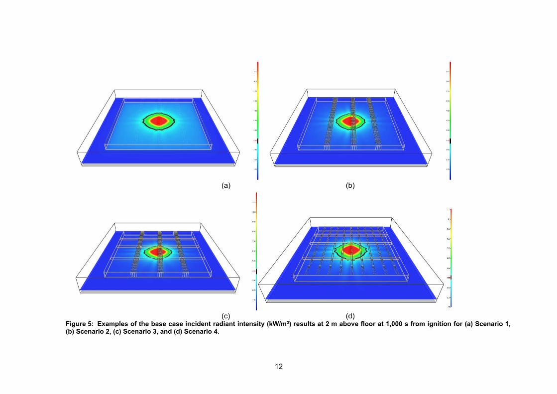
A schematic of the generic warehouse showing the general placement of smoke baffles and location of the panels used as roof vents for the modelling approach is shown in Figure 3 (i.e. Scenario 3). Examples of the results at 1,000 s for each of the four base case scenarios considered are included for the virtual device temperatures (Figure 4), incident radiation flux at 1.5 m above the floor level (Figure 5), and gas temperatures at 5.5 m above the floor level (Figure 6). Details of the scenarios, results and analysis are included in Part 1, Section 4 of this series of reports (Robbins & Wade 2008a).
x
z
y
Figure 3: Schematic of the generic warehouse showing the general placement of the panels to be used as roof vents assumed in modelling when applying a CFD approach. (N.B. Not to scale.)

10
25.526
.527
.5
40.541
.542
.5
54.555
.556
.510.5
14.5
18.5
22.5
26.5
30.5
34.5
38.5
42.5
46.5
50.5
54.5
58.5
62.5
66.5
0
20
40
60
80
100
120
Dev
ice
Tem
pera
ture
(deg
C)
X (m)
Y (m)
(a)
25.5
26.5
27.5
40.5
41.5
42.5
54.5
55.5
56.5
10.5
15.5
20.5
25.5
30.5
35.5
40.5
45.5
50.5
55.5
60.5
65.5
0
20
40
60
80
100
120
Dev
ice
Tem
pera
ture
(deg
C)
X
Y
(b)

11
25.5
26.5
27.5
40.5
41.5
42.5
54.5
55.5
56.5
10.5
14.5
18.5
22.5
26.5
30.5
34.5
38.5
42.5
46.5
50.5
54.5
58.5
62.5
66.5
0
20
40
60
80
100
120
Dev
ice
Tem
pera
ture
(deg
C)
X
Y
(c)
16.5
22.5
28.5
34.5
40.5
46.5
52.5
58.5
64.5
16.5
23.5
30.5
37.5
44.5
51.5
58.50
20
40
60
80
100
120
Dev
ice
Tem
pera
ture
(deg
C)
X
Y
(d)
Figure 4: Examples of the base case virtual heat detector temperature results at 1,000 s from ignition for (a) Scenario 1 – no vents and no smoke baffles, (b) Scenario 2 – roof panel vents and no smoke baffles, (c) Scenario 3 – roof panel vents with smoke baffles, and (d) Scenario 4 – thermally activated dedicated vents with smoke baffles.
12
(a) (b)
(c) (d)
Figure 5: Examples of the base case incident radiant intensity (kW/m²) results at 2 m above floor at 1,000 s from ignition for (a) Scenario 1, (b) Scenario 2, (c) Scenario 3, and (d) Scenario 4.

13
(a) (b)
(c) (d)
Figure 6: Examples of the base case gas temperatures (°C) results at 5.5 m above floor at 1,000 s from ignition for (a) Scenario 1, (b) Scenario 2, (c) Scenario 3, and (d) Scenario 4.

14
5.1 Conclusions from the Modelling Investigation The important aspects highlighted in the results of the modelling investigation include:
1. It is imperative that the intent of ‘effective fire venting’ is defined by the regulator.
2. Buoyancy-driven vents have a high sensitivity to ambient wind conditions. This is expected in particular for winds that are not parallel to the ground.
3. Not all potential passive roof venting panel points open in a smoke reservoir in the event of a fire in the design considered here, therefore the location of panels relative to every point on the floor is important. It is essential that the design for the width and spacing of the passive fire venting panels and building height ensures sufficient panel area for potential exposure to sufficiently hot gases to form holes in the material no matter where a fire may occur within the compartment.
4. Larger fires provide heat to a vent earlier, therefore openings form earlier. Conversely a fire may be sufficiently small as to not provide sufficient heat to a passive venting panel to form any openings and the compartment may subsequently smoke log. Therefore in this situation or other situations of failure of the passive venting panels to form holes, a way to manually open the panels may be desirable. Similarly higher compartment heights lead to a delay in gas temperatures under the vents. Therefore the selection of the design fire in combination with the building design is important to ensure conservative model results. For example, including a design fire that is slightly smaller than what would be required to form openings or have vents activate is recommended.
5. The more potential roof venting area close to the seat of the fire, the more effective the venting is at reducing the temperatures within the compartment.
6. The effective RTI and effective activation temperature values would need to be estimated from testing for each material and building design. Underestimating these values would provide model results that overestimate the fire venting effectiveness in the design.
7. Draught curtains limit the spread of hot gases across the ceiling of the compartment and aids passive venting of hot gases and smoke.
8. Quasi-steady-state conditions were observed to form within the vented compartment for the scenarios considered. Therefore finding a combination of appropriate materials and appropriate location of passive venting panels for a compartment design may be able to achieve the performance criteria, discussed in Section 3.2, or other selected values for a defined range of design fires and the ambient conditions.
These results are important aspects of design of passive buoyancy-driven roof venting and should be considered in both design and assessment stages.
Specific modelling related conclusions:
Passive roof venting can be modelled using the FDS package. However care must be taken when defining the model and the conditions to which it would be subjected. This attention to the modelling of passive fire roof venting is applicable to all modelling approaches.
For the scenarios considered here and the specific FDS package, the multiple meshes are not appropriate for use in a large single firecell, since interactions with walls provide flow that is counter to the direction of the flow accounted for

15
when passing information between meshes (i.e. from a lower numbered mesh to a higher numbered mesh).
The scenarios considered here used a 0.5 m or a 0.15 m uniform mesh. In particular, the 0.5 m mesh provided conservative results concerning the activation time of thermally activated devices since the temperatures were lower than expected. The results for maximum temperatures and radiative intensity are considered to be lower than expected in reality. However the focus of this study was the modelling of vents and the comparison between modelled scenarios.

16
6. GENERAL CONCLUSIONS The intent and associated performance criteria for fire venting must be defined by the regulator.
The intent of fire venting, in terms of the New Zealand Compliance Document C/AS1, assumed for this study is:
Fire venting is to reduce the hot combustion products contained within the firecell and help reduce hot smoke logging of the firecell.
Fire venting is not associated with protection of property or contents of the burning building.
Fire venting is not associated with the escape of initial building occupants in the event of a fire.
Fire venting is to assist in potential rescue and suppression operations of the Fire Service. The presence of fire venting does not imply the Fire Service can/would or should enter the building. Reliance on intervention by the Fire Service is not included in a building design.
Fire venting, in conjunction with other design features, may assist in the protection of other property during the total burnout of the building by reducing fire severity via preflashover venting.

17
7. DISCUSSION OF LIMITATIONS OF FIRE VENTING Passive fire venting has several limitations, including:
Fire venting will not control a fire.
Fire venting is not associated with protection of property or contents of the burning building. A compartment with passive fire venting and no fire suppression systems is expected to be completely lost in the event of a fire. Intervention by the Fire Service may prevent complete loss of the initial compartment.
Passive fire venting is highly sensitive to ambient wind conditions, to the extent that local ambient conditions may push fresh air through the roof vents or across the compartment between make-up air vents, which could stir up the smoke layer within the compartment obscuring visibility compared to still ambient conditions.
There are no existing standard test methods measuring venting effectiveness that apply to the type of passive roofing panel system investigated in this research and that could be directly adopted by designers or the regulator. While parameters defining a possible testing methodology have been identified in this work, if a national standard were to be developed it would only have application within New Zealand.

18
8. RECOMMENDATIONS FOR PASSIVE FIRE VENTING PRACTICES UTILISING ROOFING PANELS
Based on the results of this study the recommendations for passive fire venting practices using roof panels include:
1. A thermally-activated fire alarm system with direct connection to the fire service to be mandatory, to reduce the potential time to first fire suppression activities.
2. Building design to include appropriate smoke reservoirs and low-level vents to supply make-up air (such as required in AS 1668 Part 3 2001 or a similar standard).
3. Vent materials must form an opening upon exposure to hot combustion gases (with no flame impingement and no radiation component) under the material’s self-weight (without relying on the separation of other building components due to movement and partial collapse of the structure during a fire event) and in the configuration to be used in construction (e.g. when wire mesh is installed at the underside of the panel, etc).
4. Vent behaviour and characteristics must be proven by appropriate testing. The method of test needs to be confirmed by the regulator and guidance provided by this research can be used to inform that decision. However, it is noted that a suitable standard method of test does not currently exist and therefore an agreed method of test or national standard is required. This research could be as the basis for a draft standard or test protocol.
5. Instead of using a percentage of the firecell floor area, a more appropriate approach may be:
a. A minimum distance between passive fire venting panels that is dependent on minimum clear height (i.e. between the ceiling and the uppermost potential base for a fire), e.g. 0.25 x clear height, in combination with
b. A minimum potential vent area, e.g. 2 m² within a radius of 5 m (based on ceiling jet temperature estimates for a 8 MW steady fire), from any point in the area of the compartment.
However this must be reconciled with an estimate of the plume temperature at the vent location/height depending on the intended compartment fire load, which will also provide an estimate of the volume production rate of hot gases to be vented and subsequently the area of venting required. This recommendation is based on it being more important to have openings formed at earlier times during the fire growth period than potential intermittent plugholing effects at later stages in the fire development.
6. Fire venting systems must be designed to maintain:
a. the incident radiation flux below a maximum at a specified height, e.g. 4.5 kW/m² at 1.5 m above the floor,
b. the smoke temperature below a maximum depending on the intended building contents, e.g. 400°C, to delay ignition of other materials via radiation from the hot layer of gases and flashover, and
c. the layer height above a minimum, e.g. 2 m above floor height.
7. Based on the limitations of fire venting, it is not recommended that the presence of fire venting allow unlimited compartment floor area. Instead it is suggested

19
that the maximum compartment floor area allowable due to compartmentalisation be doubled when fire venting is present.
8. To be used for compartments up to FHC 3. Further research is required for potential use of roof panels for fire venting in FHC 4 compartments.
9. Instead of roof panels, consider the use of dedicated thermally-activated fire vents for which there are existing design, testing and installation standards, e.g. AS 1665 (2001), AS 2665 (2001) and AS 2428 (2004), or NFPA 204 (2002), etc.
It is to be noted that these recommendations are general suggestions to improve the current passive fire venting practices used in New Zealand.

20
8.1 Recommendations for Future Work Recommended Experimental Research:
Large-/Full- scale testing for comparison to reduced-scale and small-scale experiment results to determine applicability of small-scale test results and appropriate performance criteria for passive buoyancy-driven venting utilising roof sheeting.
Recommended further Modelling Research:
Investigation of ratios of fire to compartment volume for modelling using different approaches for this scale of building to determine appropriate limits for future design analysis.
Investigation of modelling using reduced-scale experiment data compared to large-/full- scale experiment results to determine appropriate modelling limits and criteria for use in future design analysis.
Standards development:
Should the regulator decide that a standard method of test be required for citation in the Building Code compliance document, then further work is required to draft a suitable national standard or other publication containing the agreed test protocol.

21
9. REFERENCES 9.1 Regulations and Standards AS 1668 The Use of Ventilation and Airconditioning in Buildings, Part 3: Smoke Control
Systems for Large Single Compartments or Smoke Reservoirs. 2001. Standards Association of Australia, North Sydney, Australia.
AS 2428 Methods of Testing Smoke/Heat Release Vents, Method 1: Determination of
resistance to leakage during rain. 2004. Standards Association of Australia, North Sydney, Australia.
AS 2428 Methods of Testing Smoke/Heat Release Vents, Method 2: Determination of ability
to operate under wind loading. 2004. Standards Association of Australia, North Sydney, Australia.
AS 2428 Methods of Testing Smoke/Heat Release Vents, Method 3: Determination of
operating characteristics. 2004. Standards Association of Australia, North Sydney, Australia.
AS 2428 Methods of Testing Smoke/Heat Release Vents, Method 4: Determination of the
effect of flame contact. 2004. Standards Association of Australia, North Sydney, Australia.
AS 2428 Methods of Testing Smoke/Heat Release Vents, Method 5: Determination of
discharge coefficient and effective aerodynamic area. 2004. Standards Association of Australia, North Sydney, Australia.
AS 2428 Methods of Testing Smoke/Heat Release Vents, Method 6: Determination of ability
to operate under snow loading. 2004. Standards Association of Australia, North Sydney, Australia.
AS 2665 Smoke/Heat Venting Systems: design, installation and commissioning. 2001.
Standards Association of Australia, North Sydney, Australia. BS 7346 Components for smoke and heat control systems. Part 1: Specification for natural
smoke and heat exhaust ventilators. 1990. British Standards Institute, London, UK. Compliance Document for New Zealand Building Code Clauses C1, C2, C3, C4 Fire Safety.
(Including Amendments to October 2005). 2001. Victoria University Book Centre, Wellington, New Zealand.
NFPA 204, Guide for Smoke and Heat Venting. 2002. National Fire Protection Association,
Quincy. Uniform Building Code, Volume 1: Administrative, Fire- and Life-Safety, and Field Inspection
Provisions. 1997. International Conference of Building Officials, Whittier, CA, USA. Uniform Building Code, Volume 3: Material, Testing and Installation Standards. 1997.
International Conference of Building Officials, Whittier, CA, USA.

22
9.2 General References Australasian Fire and Emergency Services Authority Council (AFAC). 2006. Fire Brigade
Intervention Model. Australasian Fire and Emergency Services Authority Council. Victoria, Australia.
Butcher, E.G. and Parnell, A.C. 1979. Smoke Control in Fire Safety Design. William Clowes.
London, UK. Edwards APR, Soja E and Wade CA. 2007. Effective Passive Roof Venting in the Event of
Fire – Literature Review. BRANZ Study Report SR 165. BRANZ Ltd, Judgeford, New Zealand.
International Fire Engineering Guidelines. 2005. Australian Building Codes Board, Canberra.
Australia. Marchant, R., Kurban, N. and Wise, S. 1999. Development and Application of the Fire
Brigade Intervention Model. Proceedings First International Conference on Fire Service Deployment Analysis, 19 & 20 March, Indianapolis, Indiana. Institution of Fire Engineers, USA.
Marchant, R., Kurban, N. and Wise, S. 2001. Development and Application of the Fire
Brigade Intervention Model. Fire Technology. 37(3):263-278. Milke JA and Klote JH. 1998. Smoke Management in Large Spaces in Buildings for Building
Control Commission of Victoria and The Broken Hill Proprietary Company Limited. Building Control Commission, Victoria, Australia.
Morgan HP and Gardner JP. 1990. Design Principles for Smoke Ventilation in Enclosed
Shopping Centres, BR 186. Fire Research Station, Building Research Establishment, Borehamwood, UK.
Thomas PH, Hinkley PL, Theobald CR and Simms, DL. 1963. Investigations into the Flow of
Hot Gases in Roof Venting. Department of Scientific and Industrial Research and Fire Offices’ Committee, Joint Fire Research Organisation, Her Majesty's Stationery Office, London, UK.
Robbins AP and Wade CA. 2008a. Effective Passive Roof Venting using Roof Panels in the
Event of Fire. Part 1: Preliminary Modelling Results. BRANZ Study Report SR 197. BRANZ Ltd, Judgeford, New Zealand.
Robbins AP and Wade CA. 2008b. Effective Passive Roof Venting using Roof Panels in the
Event of Fire. Part 2: Preliminary Experimental Results. BRANZ Study Report SR 198. BRANZ Ltd, Judgeford, New Zealand.