study on writing transmission metal grating with pulse shaping
TRANSCRIPT

Journal of Physics Conference Series
OPEN ACCESS
Study on Writing Transmission Metal Grating withPulse Shaping of Femtosecond LaserTo cite this article X C Ni et al 2006 J Phys Conf Ser 48 189
View the article online for updates and enhancements
You may also likeTwo-dimensional plasmons in aGaNAlGaN heterojunctionM Ya Vinnichenko V A Shalygin M DMoldavskaya et al
-
A Full-Wave Analysis of Surface AcousticWaves Propagating on a SiO2OverlayMetal GratingRotated Y-Cut X-Propagating LiNbO3 Substrate StructureYiliu Wang Ken-ya Hashimoto TatsuyaOmori et al
-
Colorless movement of focal spot witharbitrary velocity based on mirrors withspecial shapeQuanping Fan Shenglin Wen ShaoyiWang et al
-
This content was downloaded from IP address 198200104148 on 22112021 at 2342
Study on Writing Transmission Metal Grating with Pulse Shaping of Femtosecond Laser
X C Ni12 Q Sun2 Ch Y Wang2 L Yang2 Y Z Wu2 W Jia2 and L Chai2
1 Electronic Engineering Department Tianjin University of Technology and Education 300222 Tianjin China 2 Key Laboratory of Optoelectronic Information Technical Science EMC Ultrafast Laser Laboratory School of Precision Instruments and Optoelectronics Engineering Tianjin University 300072 Tianjin China
E-mail jpconfioporg nixiaochangtjueducn
Abstract Pulse shaping in femtosecond(fs) laser micromachining is different from that of traditional laser whose main purpose is to reduce focal scale size wipe off fluorescence around laser beam decrease pulse distortion and fabricate all kinds of figures To describe the spatial form of laser pulse around focal scale the synchronous moving of focal objective and accepting material is presented When a pinhole mask is placed in front of focal objective the changing trend of laser spatial form around focal point with the laser beam diameter will be obtained by the diameter changing of the hole mask Experimental results show that the diameter of laser pulse around focal point trends smoothly when the pinhole diameter is modulated to smaller even the position of beam waist is changed These phenomena can be explained by optical imaging theory Finally the transmission metal grating is written successfully with a selected parameter
1 Introduction Fs laser has been used in the micromachining domain at the beginning of the 1990s [1] Because the fs laser has higher peak power than longer pulse laser with the same average power it has same significant advantages over conventional laser machining such as a precise ablation threshold regular micromachining border layer after layer micromachining and no choice to ablation material [2] Many recent investigations of micromachining with fs laser have demonstrated the potential applications in micro-optics micro-electronics micro-machine micro-biology and micro-iatrology subject [2-5] The corresponding method will be chosen to realize research purpose which is changed by the idiographic experiments And that the method is corresponded to the character of subject So machining technics of fs laser as a techniques attracts more and more researcherrsquos attention [6 7]
Usually laser shaping is realized by the optical components inner or outer laser cavity But fs laser shaping is different from the traditional shaping some optical components are placed in the light pass such as beam expender filter and diffraction template And the main purpose is to reduce focal scale size wipe off the fluorescence around beam decrease pulse distortion and fabricate all kinds of figures which bases on the high peak power of the fs laser The two more popular techniques of fs laser shaping are spatial filtering and mask controlling [8 9] Spatial filtering can get rid of fluorescence around gaussian beam to improve the quality of laser beam on focal scale but it usually
Institute of Physics Publishing Journal of Physics Conference Series 48 (2006) 1011ndash1016doi1010881742-6596481189 International Symposium on Instrumentation Science and Technology
1011copy 2006 IOP Publishing Ltd
need a group of optical lens And mask controlling can modulate pulse form to realize fabrication aim by the shape of mask
In this paper the synchronous moving of focal objective and accepting material is presented which main purpose is to describe the spatial form of laser pulse around focal scale When a hole mask is placed in front of focal objective the changing trend of laser spatial form with laser beam diameter will be obtained by the variety of the hole maskrsquos diameter Finally the transmission metal grating with very smooth border is written successfully on accepting material by a selected parameter
2 Methodology and results A commercial femtosecond laser workstation (UMW-2110i Clark-MXR Inc) with a center wavelength of 775nm based on chirped pulse amplification technique (CPA) was used for the ablation experiments The pulse duration is 148fs which was measured by a scanning autocorrelator (MiNi) And 1kHz repetition rate was selected in this study The system provides variable output energies up to 1mJ per pulse which can be calculated from the average output power A selected pulsed energy is realized through the attenuator after output mirror of the fs-laser system The diameter of laser beam before focal objective is five millimeter And the pinhole maskrsquos diameter can vary from 05 to 10mm Accepting material is Au film around 300nm which was deposited on silica substrates by sputter method After hole mask the fs laser was focused on Au film surface by a 5times objective with 40mm work distance The spatial form of laser pulse around focal scale can be described as a two-dimension figure on surface of Au film by synchronous moving of focal objective and film(the velocity of them is 03mms in experiment) And the experimental results were characterized by an optical microscope (Hirox Inc which can magnify target 3500 times) and SEM
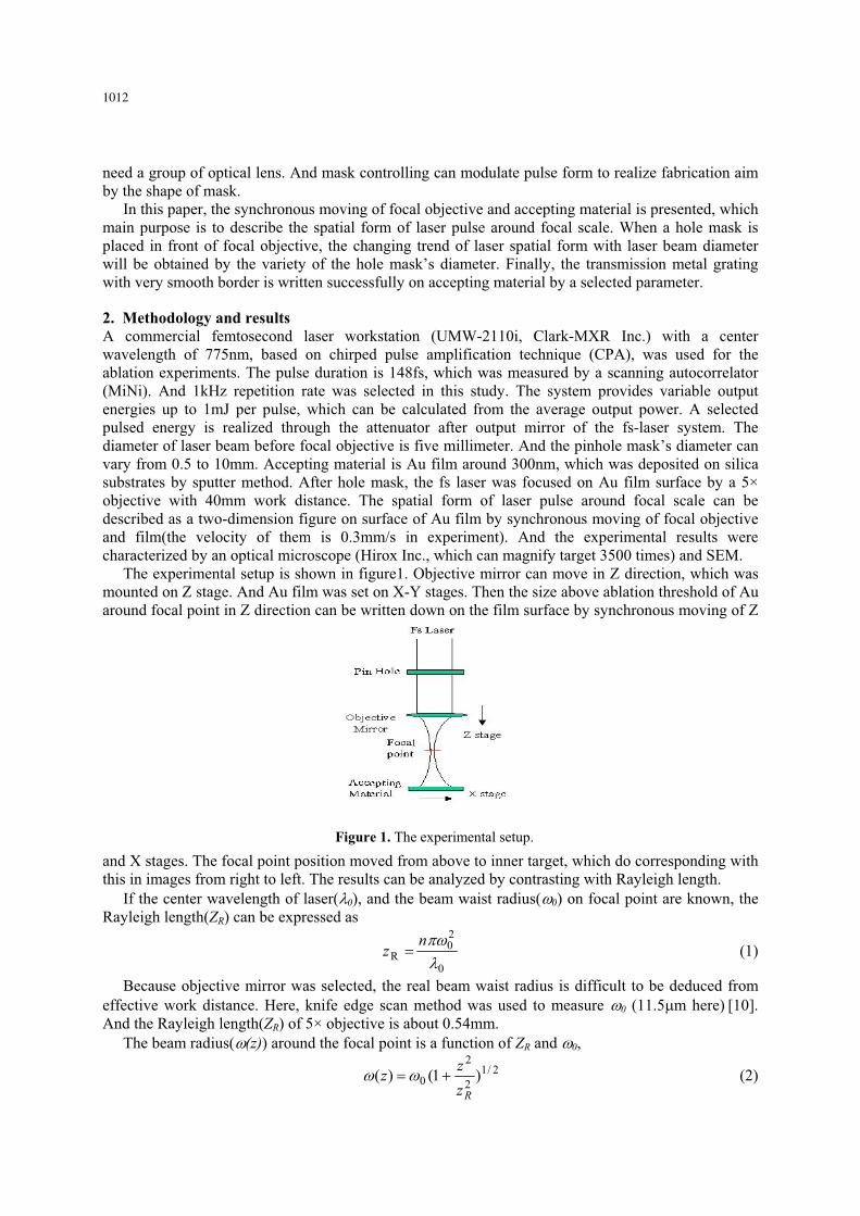
The experimental setup is shown in figure1 Objective mirror can move in Z direction which was mounted on Z stage And Au film was set on X-Y stages Then the size above ablation threshold of Au around focal point in Z direction can be written down on the film surface by synchronous moving of Z
and X stages The focal point position moved from above to inner target which do corresponding with this in images from right to left The results can be analyzed by contrasting with Rayleigh length
If the center wavelength of laser( 0) and the beam waist radius( 0) on focal point are known the Rayleigh length(ZR) can be expressed as
0
20
Rn
z (1)
Because objective mirror was selected the real beam waist radius is difficult to be deduced from effective work distance Here knife edge scan method was used to measure 0 (115 m here) [10] And the Rayleigh length(ZR) of 5times objective is about 054mm
The beam radius( (z)) around the focal point is a function of ZR and 0
212
2
0 )1()(Rz
zz (2)
Figure 1 The experimental setup
1012
The diameter of pinhole in figure 1 was modulated to observe the change trend of laser trace around the focal point in Z direction Two cases retaining the pulse energy before and after pinhole as a constant were adopted respectively All the results of the transmission form were written down on Au surface Figure 2 and 3 are images of the two cases in which single pulse energy is 917μJ before and after pinhole respectively the diameter of pinhole from top to bottom(D) is 432mm and both Z and X stages have 600μm travel
Figure 2 and 3 show the ablated scales are symmetrical around the focal point and when focal point position was moved away target surface the corresponding trace sizes are changed to larger quickly like a taper at the focal point When the pinhole was used and the diameter size was changed to smaller the corresponding trace sizes are changed very gently That is to say whether focal point is on target surface or not the laser pulse spatial form changed very slowly even the beam waist moved close to objective from focal point(see the bottom case D=2mm in figure 2 and 3) While the single pulse energy was increasing to retain the energy after pinhole as a constant the ablated results have not difference in evidence (figure 3) but the trace size is lager than figure 2 These phenomena can be explained from equation(1) and (2) When the pinhole was set before objective mirror the beam waist on the surface of objective mirror changed to smaller for the limit of hole diameter and the beam waist on focal point( 0) was larger Then the Rayleigh length(ZR) would be larger according as equation(1) and then beam waist around focal point( (z)) depended on Z very weakly So the smooth ablated images were obtained in figure 2 and 3 when pinhole was used
Figure 2 Laser-produced trace on Au film versus diameter of pin hole (transmission image and pulse energy is measured before hole mask)
Figure 3 Laser-produced trace on Au film versus diameter of pin hole (transmission image and pulse energy is measured after hole mask)
Figure 4-7 give the experimental images when pulse energy which is measured before pinhole has been changed around the Au file ablation threshold and both Z and X stages also have 600 m travel While the hole diameter is changed to very smaller the laser pulse energy after pinhole will lower than film threshold So there are four ablated traces in figure 5 and 6 even only three traces in figure 7
1013
There are no obvious taper around focal point whenever there is pinhole or not while the pulse energy is around film threshold in figure 4-7 but laser trace is more smoother when pinhole is set in light pass which is an advantage for the research of deep drilling hole and cutting materials When the hole diameter is 4mm the pulse energy is nearly no effect on laser trace Otherwise the ablated areas are shorter and shorter when pulse energy is lower because the pinhole limits most part of laser energy to pass and the fluence area(that of above threshold) will be shorter in laser spatial form The other phenomenon is that the smallest beam waist position is also closer to objective mirror like figure 2 and 3 This can be explained well by the relationship of beam waist radius on focal point and the distance from laser waist to focal mirror surface before focal objective [11]
From the results above stainless steel plate was drilled by fs laser with and without pinhole respectively(figure 89) and single pulse energy before hole is 90μJ
After compared with two figures above the border of ablated results is very clear and little crack in figure 8 which profits from the character that beam waist around focal point or laser trace is more smoother with pinhole in light pass This technique is very useful for the research to drill hole with high depth rate on material Figure 10 is a SEM image of transmission grating on Cu foil(01mm thick) with clear border which was fabricated by fs laser workstation with optimized parameter((D=4mm single pulse energy after hole is 80μJ)) Further study is being conducted in our lab
Figure 5 Laser-produced trace on Au film versus laser pulse energy(D=4mm and pulse energy is 128 88 61 36μJ from top to bottom respectively)
Figure 4 Laser-produced trace on Au film versus laser pulse energy(no pin hole and pulse energy is 128 88 61 36 16μJ from top to bottom respectively)
Figure 6 Laser-produced trace on Au filmversus laser pulse energy(D=3mm and pulse energy is 128 88 61 36μJ from top to bottom respectively)
Figure 7 Laser-produced trace on Au film versus laser pulse energy(D=2mm and pulse energy is 128 88 61μJ from top to bottom respectively)
1014
3 Conclusion To study fs laser micomachining technics we have analyzed the effect of pinhole mask technique on fs laser spatial transform around focal point It was found that beam waist around focal point or laser trace is more smoother when pinhole is set before objective And optimized parameter has been obtained for drilling hole with high depth rate on material Finally a transmission grating on Cu foil is fabricated with the parameter
Acknowledgements This work was supported by the Key Grant Project of Chinese Ministry of Education (No10410) by the Tianjin University of Technology and Education Fund (NoKYQD06001) and by the Science and technology development project fund of Tianjin city (No043103911)
References [1] Kumagai H Midorikawa K and Toyoda K 1994 Appl Phys Lett 65 1850-52 [2] Ni X C and Wang Ch Y 2002 laser optronics progress 39 4-9 [3] Kondo Y Nouchi K Mitsuyu T Watanabe M Kazansky PG and Hirao K 1999 Opt Lett 24
646-648 [4] Winick K A and Florea C 2003 J Lightwave Technol 21 246-253 [5] Sowa S Watanabe W Tamaki T and Nishii J 2006 Opt Express 14 291-297 [6] Tan B Venkatkrishnan K Sivakumar N R and Gan G K 2003 Opt Laser Technol 35 199-202 [7] Kawamura D Takita A Hayasaki Y and Nishida N 2006 Appl Phys A Materials Science and
Processing 82 523-527 [8] Venkatakrishnan K Stanley P and Lim L E N 2002 J Micromech Microeng 12 775-779 [9] Nakata Y Okada T and Maeda M 2004 Opt Lasers Eng 42 389-393
Figure 8 Circle deep hole image on surface of stainless steel plate (D=4mm)
Figure 9 Circle deep hole image on surface of stainless steel plate (D= )
Figure 10 SEM image of a transmission grating on Cu foil
1015
[10] Li J P Cao Sh Y Wu Z B Wang Y G Zhang Zh G Zhao Y B and Zhu X N 2005 Nanotechnol precision eng 3 142-145
[11] Zhou B K Gao Y Zh Chen T R and Chen J Y 2000 Principles of Laser (Beijing National Defence Industry Press) P 81
1016

Study on Writing Transmission Metal Grating with Pulse Shaping of Femtosecond Laser
X C Ni12 Q Sun2 Ch Y Wang2 L Yang2 Y Z Wu2 W Jia2 and L Chai2
1 Electronic Engineering Department Tianjin University of Technology and Education 300222 Tianjin China 2 Key Laboratory of Optoelectronic Information Technical Science EMC Ultrafast Laser Laboratory School of Precision Instruments and Optoelectronics Engineering Tianjin University 300072 Tianjin China
E-mail jpconfioporg nixiaochangtjueducn
Abstract Pulse shaping in femtosecond(fs) laser micromachining is different from that of traditional laser whose main purpose is to reduce focal scale size wipe off fluorescence around laser beam decrease pulse distortion and fabricate all kinds of figures To describe the spatial form of laser pulse around focal scale the synchronous moving of focal objective and accepting material is presented When a pinhole mask is placed in front of focal objective the changing trend of laser spatial form around focal point with the laser beam diameter will be obtained by the diameter changing of the hole mask Experimental results show that the diameter of laser pulse around focal point trends smoothly when the pinhole diameter is modulated to smaller even the position of beam waist is changed These phenomena can be explained by optical imaging theory Finally the transmission metal grating is written successfully with a selected parameter
1 Introduction Fs laser has been used in the micromachining domain at the beginning of the 1990s [1] Because the fs laser has higher peak power than longer pulse laser with the same average power it has same significant advantages over conventional laser machining such as a precise ablation threshold regular micromachining border layer after layer micromachining and no choice to ablation material [2] Many recent investigations of micromachining with fs laser have demonstrated the potential applications in micro-optics micro-electronics micro-machine micro-biology and micro-iatrology subject [2-5] The corresponding method will be chosen to realize research purpose which is changed by the idiographic experiments And that the method is corresponded to the character of subject So machining technics of fs laser as a techniques attracts more and more researcherrsquos attention [6 7]
Usually laser shaping is realized by the optical components inner or outer laser cavity But fs laser shaping is different from the traditional shaping some optical components are placed in the light pass such as beam expender filter and diffraction template And the main purpose is to reduce focal scale size wipe off the fluorescence around beam decrease pulse distortion and fabricate all kinds of figures which bases on the high peak power of the fs laser The two more popular techniques of fs laser shaping are spatial filtering and mask controlling [8 9] Spatial filtering can get rid of fluorescence around gaussian beam to improve the quality of laser beam on focal scale but it usually
Institute of Physics Publishing Journal of Physics Conference Series 48 (2006) 1011ndash1016doi1010881742-6596481189 International Symposium on Instrumentation Science and Technology
1011copy 2006 IOP Publishing Ltd
need a group of optical lens And mask controlling can modulate pulse form to realize fabrication aim by the shape of mask
In this paper the synchronous moving of focal objective and accepting material is presented which main purpose is to describe the spatial form of laser pulse around focal scale When a hole mask is placed in front of focal objective the changing trend of laser spatial form with laser beam diameter will be obtained by the variety of the hole maskrsquos diameter Finally the transmission metal grating with very smooth border is written successfully on accepting material by a selected parameter
2 Methodology and results A commercial femtosecond laser workstation (UMW-2110i Clark-MXR Inc) with a center wavelength of 775nm based on chirped pulse amplification technique (CPA) was used for the ablation experiments The pulse duration is 148fs which was measured by a scanning autocorrelator (MiNi) And 1kHz repetition rate was selected in this study The system provides variable output energies up to 1mJ per pulse which can be calculated from the average output power A selected pulsed energy is realized through the attenuator after output mirror of the fs-laser system The diameter of laser beam before focal objective is five millimeter And the pinhole maskrsquos diameter can vary from 05 to 10mm Accepting material is Au film around 300nm which was deposited on silica substrates by sputter method After hole mask the fs laser was focused on Au film surface by a 5times objective with 40mm work distance The spatial form of laser pulse around focal scale can be described as a two-dimension figure on surface of Au film by synchronous moving of focal objective and film(the velocity of them is 03mms in experiment) And the experimental results were characterized by an optical microscope (Hirox Inc which can magnify target 3500 times) and SEM
The experimental setup is shown in figure1 Objective mirror can move in Z direction which was mounted on Z stage And Au film was set on X-Y stages Then the size above ablation threshold of Au around focal point in Z direction can be written down on the film surface by synchronous moving of Z
and X stages The focal point position moved from above to inner target which do corresponding with this in images from right to left The results can be analyzed by contrasting with Rayleigh length
If the center wavelength of laser( 0) and the beam waist radius( 0) on focal point are known the Rayleigh length(ZR) can be expressed as
0
20
Rn
z (1)
Because objective mirror was selected the real beam waist radius is difficult to be deduced from effective work distance Here knife edge scan method was used to measure 0 (115 m here) [10] And the Rayleigh length(ZR) of 5times objective is about 054mm
The beam radius( (z)) around the focal point is a function of ZR and 0
212
2
0 )1()(Rz
zz (2)
Figure 1 The experimental setup
1012
The diameter of pinhole in figure 1 was modulated to observe the change trend of laser trace around the focal point in Z direction Two cases retaining the pulse energy before and after pinhole as a constant were adopted respectively All the results of the transmission form were written down on Au surface Figure 2 and 3 are images of the two cases in which single pulse energy is 917μJ before and after pinhole respectively the diameter of pinhole from top to bottom(D) is 432mm and both Z and X stages have 600μm travel
Figure 2 and 3 show the ablated scales are symmetrical around the focal point and when focal point position was moved away target surface the corresponding trace sizes are changed to larger quickly like a taper at the focal point When the pinhole was used and the diameter size was changed to smaller the corresponding trace sizes are changed very gently That is to say whether focal point is on target surface or not the laser pulse spatial form changed very slowly even the beam waist moved close to objective from focal point(see the bottom case D=2mm in figure 2 and 3) While the single pulse energy was increasing to retain the energy after pinhole as a constant the ablated results have not difference in evidence (figure 3) but the trace size is lager than figure 2 These phenomena can be explained from equation(1) and (2) When the pinhole was set before objective mirror the beam waist on the surface of objective mirror changed to smaller for the limit of hole diameter and the beam waist on focal point( 0) was larger Then the Rayleigh length(ZR) would be larger according as equation(1) and then beam waist around focal point( (z)) depended on Z very weakly So the smooth ablated images were obtained in figure 2 and 3 when pinhole was used
Figure 2 Laser-produced trace on Au film versus diameter of pin hole (transmission image and pulse energy is measured before hole mask)
Figure 3 Laser-produced trace on Au film versus diameter of pin hole (transmission image and pulse energy is measured after hole mask)
Figure 4-7 give the experimental images when pulse energy which is measured before pinhole has been changed around the Au file ablation threshold and both Z and X stages also have 600 m travel While the hole diameter is changed to very smaller the laser pulse energy after pinhole will lower than film threshold So there are four ablated traces in figure 5 and 6 even only three traces in figure 7
1013
There are no obvious taper around focal point whenever there is pinhole or not while the pulse energy is around film threshold in figure 4-7 but laser trace is more smoother when pinhole is set in light pass which is an advantage for the research of deep drilling hole and cutting materials When the hole diameter is 4mm the pulse energy is nearly no effect on laser trace Otherwise the ablated areas are shorter and shorter when pulse energy is lower because the pinhole limits most part of laser energy to pass and the fluence area(that of above threshold) will be shorter in laser spatial form The other phenomenon is that the smallest beam waist position is also closer to objective mirror like figure 2 and 3 This can be explained well by the relationship of beam waist radius on focal point and the distance from laser waist to focal mirror surface before focal objective [11]
From the results above stainless steel plate was drilled by fs laser with and without pinhole respectively(figure 89) and single pulse energy before hole is 90μJ
After compared with two figures above the border of ablated results is very clear and little crack in figure 8 which profits from the character that beam waist around focal point or laser trace is more smoother with pinhole in light pass This technique is very useful for the research to drill hole with high depth rate on material Figure 10 is a SEM image of transmission grating on Cu foil(01mm thick) with clear border which was fabricated by fs laser workstation with optimized parameter((D=4mm single pulse energy after hole is 80μJ)) Further study is being conducted in our lab
Figure 5 Laser-produced trace on Au film versus laser pulse energy(D=4mm and pulse energy is 128 88 61 36μJ from top to bottom respectively)
Figure 4 Laser-produced trace on Au film versus laser pulse energy(no pin hole and pulse energy is 128 88 61 36 16μJ from top to bottom respectively)
Figure 6 Laser-produced trace on Au filmversus laser pulse energy(D=3mm and pulse energy is 128 88 61 36μJ from top to bottom respectively)
Figure 7 Laser-produced trace on Au film versus laser pulse energy(D=2mm and pulse energy is 128 88 61μJ from top to bottom respectively)
1014
3 Conclusion To study fs laser micomachining technics we have analyzed the effect of pinhole mask technique on fs laser spatial transform around focal point It was found that beam waist around focal point or laser trace is more smoother when pinhole is set before objective And optimized parameter has been obtained for drilling hole with high depth rate on material Finally a transmission grating on Cu foil is fabricated with the parameter
Acknowledgements This work was supported by the Key Grant Project of Chinese Ministry of Education (No10410) by the Tianjin University of Technology and Education Fund (NoKYQD06001) and by the Science and technology development project fund of Tianjin city (No043103911)
References [1] Kumagai H Midorikawa K and Toyoda K 1994 Appl Phys Lett 65 1850-52 [2] Ni X C and Wang Ch Y 2002 laser optronics progress 39 4-9 [3] Kondo Y Nouchi K Mitsuyu T Watanabe M Kazansky PG and Hirao K 1999 Opt Lett 24
646-648 [4] Winick K A and Florea C 2003 J Lightwave Technol 21 246-253 [5] Sowa S Watanabe W Tamaki T and Nishii J 2006 Opt Express 14 291-297 [6] Tan B Venkatkrishnan K Sivakumar N R and Gan G K 2003 Opt Laser Technol 35 199-202 [7] Kawamura D Takita A Hayasaki Y and Nishida N 2006 Appl Phys A Materials Science and
Processing 82 523-527 [8] Venkatakrishnan K Stanley P and Lim L E N 2002 J Micromech Microeng 12 775-779 [9] Nakata Y Okada T and Maeda M 2004 Opt Lasers Eng 42 389-393
Figure 8 Circle deep hole image on surface of stainless steel plate (D=4mm)
Figure 9 Circle deep hole image on surface of stainless steel plate (D= )
Figure 10 SEM image of a transmission grating on Cu foil
1015
[10] Li J P Cao Sh Y Wu Z B Wang Y G Zhang Zh G Zhao Y B and Zhu X N 2005 Nanotechnol precision eng 3 142-145
[11] Zhou B K Gao Y Zh Chen T R and Chen J Y 2000 Principles of Laser (Beijing National Defence Industry Press) P 81
1016

[10] Li J P Cao Sh Y Wu Z B Wang Y G Zhang Zh G Zhao Y B and Zhu X N 2005 Nanotechnol precision eng 3 142-145
[11] Zhou B K Gao Y Zh Chen T R and Chen J Y 2000 Principles of Laser (Beijing National Defence Industry Press) P 81
1016