study on torsional behavior of rc t- beams...
TRANSCRIPT

Research Journal of Recent Sciences _________________________________________________ ISSN 2277-2502
Vol. 4(ISC-2014), 57-64 (2015) Res. J. Recent. Sci.
International Science Congress Association 57
Study on Torsional Behavior of RC T- Beams Strengthened with Glass FRP Sure Naveen,
Patel Asha and Jena Biswajit
Department of Civil Engineering, National Institute of Technology, Rourkela-769008, INDIA
Available online at: www.isca.in, www.isca.me Received 30th November 2014, revised 22nd January 2015, accepted 30th January 2015
Abstract
Environmental degradation, increased service loads, reduced capacity due to aging, degradation owing to poor construction
materials and workmanships and conditional need for seismic retrofitting have demanded the necessity for repair and
rehabilitation of existing structures. Fibre reinforced polymers has been used successfully in many such applications for
reasons like low weight, high strength and durability. In the present work experimental study was conducted in order to have
a better understanding the behavior of torsional strengthening of solid RC flanged T-beams. An RC T-beam is analyzed and
designed for torsion like an RC rectangular beam; the effect of concrete on flange is neglected by codes. In the present study
effect of flange part in resisting torsion is studied by changing flange width of controlled beams. The other parameters
studied are strengthening configurations and fiber orientations. The aim of present work is to determine quantitatively the
effectiveness of GFRP to be used as external lateral reinforcements to flanged T-beams subjected to torsion. Experimental
results obtained from GFRP strengthen beams are compared with un-strengthen control beams. The study shows remarkable
improvement in torsional behavior of all the GFRP strengthen T-beams. The experimentally obtained results are validated
with analytical model presented by A. Deifalla and A. Ghobarah and found in good agreement.
Keywords: GFRP, reinforced concrete, T- beam, torsional strength, shear flow.
Introduction
Torsion is considered a secondary force in the design of RCC
structures which generally accompanied with shear or flexure or
combination of both. Behavior of an RCC beam subjected to
various forces along with torsion is rather complicated . Hence
lots of research works had been carried out to understand
torsional behavior of RCC beams. In the present scenario boom
in the construction industries with huge RCC structures with
complicated planning etc may cause a complex system of forces
acting on the members of the building. This complex forces
generally consists of torsion along with other forces. Therefore
understanding of behavior of RCC members subjected to torsion
is required. Previous studies reveal that the behavior of concrete
elements in torsion is primarily governed by the tensile response
of the material, particularly its tensile cracking characteristics.
Therefore to resist torsion mainly closed vertical stirrups are
provided in the RCC beam.
Torsional stresses develop along the periphery of the section
and form a close path called shear path . Provision of vertical
stirrups take care of the torsional stresses in a rectangular beam.
Similarly shear path followed by torsional stresses in a T-beam
should go round the periphery of the section but codes neglects
the flange area of T-beam and consider only web area while
calculating torsional capacity hence rectangular stirrups are
provided in the web portion only. This leads to interruption in
the shear path and failure of flange occurs.
Natural calamities like Earthquake, Cyclone cause severe
damage to RCC structures specially with un symmetrical plans
and elevations. This un-symmetry give rise to torsion to many
elements of the structure. Some times while designing these
elements torsional effects are not considered hence necessitate
retrofitting of the elements specially for torsion.The best
solution in this regard if offered by FRP applications.In the past
many research have been done to study the effect of FRP
application on RCC elements mainly subjected to forces like
shear and flexure. The number of researches on members
subjected to torsion are limited.
Ghobarah et al.1, chalioris et al.
2, Ameli et al.
3etc conducted
experimental works to determine the effectiveness of different
types of FRP applications with different configurations and fiber
orientations to improve torsional capacity of rectangular beams.
Deifalla and Ghobarah4, Zojaji and Kabir
5 developed analytical
models for the case of the RC beams strengthened in torsion. Al
mahadi et.al.6 conducted experimental tests on beams with
CFRP strips oriented in 900 and 45
0 applied in various
configurations and anchoring systems.
Methodology
Experimental program: For the experimental study total nine
beams are cast. The concrete of M20 grade are designed with
proportion 1:1.67:3.3 and water cement ratio of 0.5. HYSD bars
of Fe415 grade are used. The beams are divided in three sets
based on the flange width. Set T2 , T3 and T4 consist of flange

Research Journal of Recent Sciences ______________________________________________________________ ISSN 2277-2502
Vol. 4(ISC-2014), 57-64 (2015) Res. J. Recent. Sci.
International Science Congress Association 58
width 250mm,350mm and 450 mm respectively. The sections
details and reinforcement details are shown in the Fig.1
First set has one beam T2. The beam is un-strengthened and cast
to study the effect of width of flange. Set T3 and T4 consists of
four beams. T3C and T4C are un-strengthen beams treated as
control beams. T3SF and T4SF are strengthen with fully
wrapped GFRP strips oriented at 900, T3SU and T4SU are
strengthen with U- wrapped GFRP strips oriented at 900 , T3S45
and T4S45 are strengthen with fully wrapped GFRP strips
oriented at 450 . Bi-directional woven GFRP fiber are used for
retrofitting the beams. The epoxy resin is used for bonding
GFRP fibers to the concrete surface. The resin and hardener
used in this study are Araldite LY 556 and hardener HY 951
respectively. Four layers of 100mm wide strips of GFRP are
used for strengthening. Three types of strengthening schemes
are adopted in the study. The details of strengthening schemes
are given in Table 1. The edge to edge spacing betweenGFRP
strips are 100 mm.
Experimental Setup: Three sets of T-beams of varying flange
widths are cast. The cross sectional details and reinforcement
arrangements are shown in the figure 1. The testing arrangement
is shown in the figure 2.
Figu
re-1
crossectionand reinforcement
Figure-2
S.F and B.M Diagram for 2-Point Loading and Loading Setup

Research Journal of Recent Sciences ______________________________________________________________ ISSN 2277-2502
Vol. 4(ISC-2014), 57-64 (2015) Res. J. Recent. Sci.
International Science Congress Association 59
All beams are tested under monotonically increasing static loads
on both projected arms simultaneously, this arrangement
transfer torsion to the middle part of the beam of 0.8 m length.
All beams are designed to fail in torsion hence no stirrups are
provided except at each end to keep longitudinal reinforcements
in positions. The beams are tested till failure in Structural
Engineering Laboratory of National Institute of Technology,
Rourkela . During testing loads are applied in increments and at
each increment deflections were observed across the three
sectionstocalculate twisting angles at different points on the
beam.
During testing cracks formation and their propagation and
inclinations are critically observed. For retrofitted beams crack
patterns and failure pattern are observed after removing the
GFRP from the beams. The details of results obtained through
testing of beams are given in Table 2.
Results and Discussion
Effect of Flange width on Torsional Moment Capacity:
Comparisons between control beams of varying flange width
exhibit that torsional resisting capacity of increases with
increase in flange width. Various codes neglect the flange area
of T-beam and consider only web area while calculating
torsional capacity unless stirrups are provided in the flange area.
The present study showed that unreinforced flange also
contributes to the torsional capacity hence conventions given in
the codes are on conservative side.
Table-1
Description of Beams
Beam
Series I
T2
Series II
T3
Series III
T4 Description
Flange width
250mm
Flange width
350mm
Flange width
450mm
Beam Designation
T2C T3C T4C Control Beam
--------------- T3SU T4SU
U wrapped with four layers of 100
mm wide strips of GFRP ,oriented
900 with horizontal.
--------------- T3SF T4SF
Fully wrapped with four layers of
100 mm wide strips of GFRP,
oriented 900 with horizontal.
--------------- T3S45 T4S45
Fully wrapped with four layers of
100 mm wide strips of GFRP
,oriented 450 with horizontal.
Table-2
Torsional capacity of Beams
Beam
Description
Beam
Designation
Ultimate load
InkN
Ultimate Torsional
Moment in kN-m Type of Failure Remark
Series T2 T2C 102 16.88 Debonding First hair line crack
appeared @80KN
Series T3
T3C 116 18.75 Debonding First hair line crack
appeared @90KN
T3SU 143 26.81 Debonding First hair line crack
appeared @110KN
T3SF 230 43.13 Debonding First hair line crack
appeared @210KN
T3S45 210 39.375 Debonding First hair line crack
appeared @190KN
Series T4
T4C 152 28.50 Debonding First hair line crack
appeared @120KN
T4SU 208 39.00 Debonding First hair line crack
appeared @160KN
T4SF 315 58.13 Debonding First hair line crack
appeared @260KN
T4S45 297 56.25 Debonding First hair line crack
appeared @230KN
Research Journal of Recent Sciences ______________________________________________________________ ISSN 2277-2502
Vol. 4(ISC-2014), 57-64 (2015) Res. J. Recent. Sci.
International Science Congress Association 60
0
5
10
15
20
25
30
0 0.005 0.01 0.015
TO
RSI
ON
AL
MO
ME
NT
(KN
-M)
ANGLE OF TWIST(RAD/M)
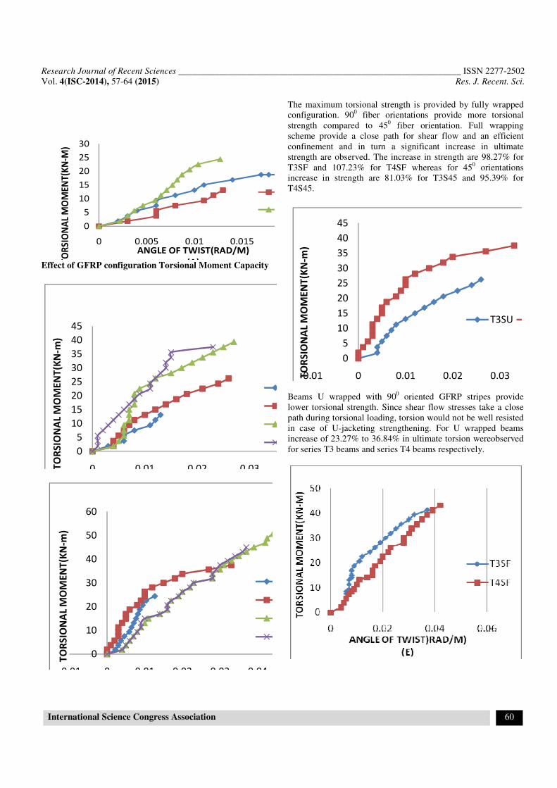
(A)Effect of GFRP configuration Torsional Moment Capacity
0
5
10
15
20
25
30
35
40
45
0 0.01 0.02 0.03TO
RS
ION
AL
MO
ME
NT
(KN
-m)
0
10
20
30
40
50
60
-0.01 0 0.01 0.02 0.03 0.04
TO
RS
ION
AL
MO
ME
NT
(KN
-m)
The maximum torsional strength is provided by fully wrapped
configuration. 900 fiber orientations provide more torsional
strength compared to 450 fiber orientation. Full wrapping
scheme provide a close path for shear flow and an efficient
confinement and in turn a significant increase in ultimate
strength are observed. The increase in strength are 98.27% for
T3SF and 107.23% for T4SF whereas for 450 orientations
increase in strength are 81.03% for T3S45 and 95.39% for
T4S45.
0
5
10
15
20
25
30
35
40
45
-0.01 0 0.01 0.02 0.03TO
RS
ION
AL
MO
ME
NT
(KN
-m)
T3SU
Beams U wrapped with 900 oriented GFRP stripes provide
lower torsional strength. Since shear flow stresses take a close
path during torsional loading, torsion would not be well resisted
in case of U-jacketing strengthening. For U wrapped beams
increase of 23.27% to 36.84% in ultimate torsion wereobserved
for series T3 beams and series T4 beams respectively.

Research Journal of Recent Sciences ______________________________________________________________ ISSN 2277-2502
Vol. 4(ISC-2014), 57-64 (2015) Res. J. Recent. Sci.
International Science Congress Association 61
0
5
10
15
20
25
30
35
40
45
0 0.01 0.02 0.03
TO
RS
ION
AL
MO
ME
NT
(KN
-M)
Figure-3
(A),(B),(C),(D),(E),(F) Are Curves Between Torsional
Moment VS. Angle Of Twist
Analytical Validation: The model used for validation of the
experimental results of present study are developed by A.
Deifalla and A. Ghobarahis a simplified procedure to evaluate
FRP contribution to torsional capacity of RC beams4. They
proposed that FRP contribution to the total torsion capacity can
be calculated by
Tf =
Where; Ao =area enclosed inside the critical shear flow path due
to strengthening includes area of flange, ff = stress in the FRP
sheet at failure, =angle of orientation of the fiber direction to
the longitudinal axis of the beam, Sf=spacing between the
centerline of the FRP strips,
Af = effective area of the FRP resisting torsion calculated by:
Af= tfwf, wf = width of FRP strips
Where n = number of FRP strips,
ff = EfƐfe
Where Ɛfe = effective strain in fibres calculated by
Ɛfe= for debonding failure of FRP
Where Le = effective bond length calculated by
Le=
Where fc = compressive strength of concrete
Following the above equations and using material properties and
specimen dimensions the torsional resistance provided by the
FRP for beams are calculated and given in Table 3
GFRP properties Ef= 9493 N/mm2
(determined by using
INSTRON UTM at structural. Engg. Lab.)
Figure-4
Beams retrofitted with GFRP oriented at 450
Research Journal of Recent Sciences ______________________________________________________________ ISSN 2277-2502
Vol. 4(ISC-2014), 57-64 (2015) Res. J. Recent. Sci.
International Science Congress Association 62
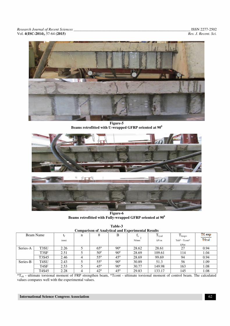
Figure-5
Beams retrofitted with U-wrapped GFRP oriented at 900
Figure-6
Beams retrofitted with Fully-wrapped GFRP oriented at 900
Table-3
Comparison of Analytical and Experimental Results
Beam Name tf
(mm)
n
θ Β fc
N/mm2
Tf,cal
kN m
Tfexp=
Tult* - Tcont*
kNm
Series-A T3SU 2.26 5 65º 90º 28.62 28.61 27 0.94
T3SF 2.51 5 50º 90º 28.69 109.61 114 1.04
T3S45 2.46 4 55º 45º 28.69 99.69 94 0.94
Series-B T4SU 2.43 5 55º 90º 30.89 51.3 56 1.09
T4SF 2.53 5 45º 90º 30.77 149.98 163 1.08
T4S45 2.28 4 42º 45º 29.83 133.17 145 1.08
*Tult - ultimate torsional moment of FRP strengthen beam, *Tcont - ultimate torsional moment of control beam. The calculated
values compares well with the experimental values.

Research Journal of Recent Sciences ______________________________________________________________ ISSN 2277-2502
Vol. 4(ISC-2014), 57-64 (2015) Res. J. Recent. Sci.
International Science Congress Association 63
Conclusion
The present experimental program consisting of nine numbers of
reinforced concrete T- beams with three different flange widths
tested under torsion. The main objective is to examine the
effectiveness of epoxy-bonded GFRP fabrics used as external
transverse reinforcement to resist torsion. Based on presented
experimental results and analytical predictions, the following
conclusions are drawn. i. Experimental results show that the
effect of flange width on torsional capacity of GFRP strengthened
RC T-beams are significant. ii. Torsional strength increases with
increase in flange area irrespective of beam strengthening with
GFRP following different configurations schemes. iii. With 250
mm wide flange width increase in strength was 13%, with
350mm wide flange was 29% and for 450mm wide flange was
found to be 69%. This is due to increase in area enclosed inside
the critical shear path. iv. The cracking and ultimate torque of all
strengthen beams were greater than those of the control beams. v.
The maximum increase in torque was obtained for 900fully
wrapped configurations. Increase of 133.33% to 116.67% in first
cracking and 155.55% to 107.23% in ultimate torsion were
recorded for series T3 beams and series T4 beams respectively.
vi. Beams fully wrapped with 450 oriented GFRP stripes showed
next highest torsional resisting capacity. Increase of 111.11% to
91.667% in first cracking and 81.03% to 95.39% in ultimate
torsion were recorded for series T3 beams and series T4 beams
respectively. vii. Beams U wrapped with 900 oriented GFRP
stripes show lowest torsional resisting capacity. Since shear flow
stresses take a close path during torsional loading ,torsion would
not be well resisted in case of U-jacketing strengthening. viii. For
U wrapped beams increase of 22.22% to 33.33% in first cracking
and 23.27% to 36.84% in ultimate torsion were recorded for
series T3 beams and series T4 beams respectively. ix.
Strengthened beams using GFRP strips as the only transverse
reinforcement exhibited better overall torsional performance than
the non-strengthened control beams. x. Although the extended
FRP U-jacket strengthening technique relatively less effective
than the FRP full wrapping strengthening technique, it yielded
promising results in terms of strength and ductility while being
quite feasible for most strengthening practical situations. xi. The
experimental results were validated with simplified model
proposed by A. DeifallaandA.Ghobarah4. The model included the
effect of different parameters studied in the present work like
strengthening techniques, thickness and number of layers, spacing
between FRP strips, FRP orientations, and angle of diagonal
cracks. xii. Experimental results indicate that the estimation of the
GFRP contribution to torsional strength using simplified model
proposed by A. Deifalla and A.Ghobarah provided good accuracy
for GFRP strengthen beams4.
Acknowledgment
The authors wish to acknowledge the support provided by the
Structural Engineering Laboratory of National Institute of
Technology, Rourkela.
References
1. Gobarah A., Ghorbel M., and Chidiac S., Upgrading
torsional resistance of RC beams using FRP, Journal of
Composites for Construction, 6, 257–263 (2002)
2. Chalioris C.E., Torsional strengthening of rectangular and
flanged beams using carbon fibre reinforced polymers –
Experimental study, Construction and Building Materials,
in press (available online since 16 Nov (2006)
3. Ameli M. and Ronagh H.R., Behavior of FRP strengthened
reinforced concrete beams under torsion, Journal of
Composites for Construction, 11(2), 192-200 (2007)
4. Deifalla A. and Ghobarah A., Full Torsional Behavior of
RC Beams Wrapped with FRP: Analytical Model, Journal
of Composites for Construction, 14, 289-300 (2010)
5. Zojaji A.R. and Kabir M.Z., Analytical approach for
predicting full torsional behavior of reinforced concrete
beams strengthened with FRP materials, ScientiaIranica,
A.19(1), 51–63 (2011)
6. Hii, A.K.Y. and Al-Mahadi R., Torsional capacity of
CFRP strengthened reinforced concrete beams, Journal of
Composites for Construction, 11, 71–80 (2007)
7. ACI Committee 440 State Of Art Report On Fiber
Reinforced Plastic (1996)
8. Zhang J.W., Lu T.Z. and Zhu H., Experimental study on
the behavior of RC torsional members externally bonded
with CFRP”. FRP composites in civil engineering, I,
Elsevier Science, New York (2001)
9. Panchacharam S. and Belarbi A., Torsionalbehavior of
reinforced concrete beams strengthened with FRP
composites, Proceedings 1st FIB Congress, Osaka, Japan,
1-10 (2002)
10. Deifalla A. and Ghobarah A., Simplified analysis for
Torsionaly Strengthen RC beams using FRP’ Proceedings
of the International Symposium on Bond Behavior of FRP
in Structures BBFS (2005)
11. Chalioris C.E., Experimental study of the torsion of
reinforced concrete members, Structural Engineering and
Mechanics, 23(6), 713-737 (2006)
12. Hii A.K.Y. and Al-Mahaidi R., An experimental and
numerical investigation on torsional strengthening of solid
and box-section RC beams using CFRP laminates, Journal
of Composite Structures, 75, 213-221 (2006)
13. Ameli M. and Ronagh H.R., Analytical method for
evaluating ultimate torque of FRP strengthened reinforced
concrete beams, Journal of Composites for Construction,
11, 384–390 (2007)
14. Chalioris C.E., Tests and analysis of reinforced concrete
beams under torsion retrofitted with FRP strips,
Proceedings 13th Computational Methods and
Research Journal of Recent Sciences ______________________________________________________________ ISSN 2277-2502
Vol. 4(ISC-2014), 57-64 (2015) Res. J. Recent. Sci.
International Science Congress Association 64
Experimental Measurements (CMEM 2007), Prague,
Czech Republic, (2007)
15. Rahal K.N., and Collins M.P., Effect of the thickness of
concrete cover on the shear-torsion interaction—An
experimental investigation, ACI Struct. J.,92, 334–342.
Reinforcement For Concrete Structure, ACI 440R-96,
American Concrete Institute , Farmington Hills, Michigan
(1995)