study on the transport phenomena in complex micro-reactors · study on the transport phenomena in...
TRANSCRIPT

Study on the Transport Phenomena in
Complex Micro-Reactors By Eric Mielke
Thesis submitted to the Faculty of Graduate and Postdoctoral Studies as required for the degree of Master of Applied Science
In
Department of Chemical and Biological Engineering Faculty of Engineering
University of Ottawa
© Eric Mielke, Ottawa, Canada, 2017
ii
Abstract
Continuous processing in the pharmaceutical and fine chemical industries, particularly in
micro/milli-scale reactors, has been a topic of interest in literature in recent years due to the
advantages offered over batch reactions. One such advantage is the enhanced transport properties
of operating at smaller scales, although the quantification of the transport phenomena is not
straightforward when wall and entrance effects cannot be neglected.
In the first study presented, various micro-mixer geometries and scales were considered to increase
the mixing efficiency in liquid-liquid systems of diverse interfacial tensions for fast reactions. The
conditions were varied over different flow regimes; including slug flow, parallel flow, and drop
flow. A mass-transfer-limited test reaction was used to evaluate the overall volumetric mass
transfer coefficients (Korga) as a function of the average rate of energy dissipation (ε) for each
mixer design. The onset of drop flow occurred at a lower ε for the LL-Triangle mixer when
compared with the Sickle or LL-Rhombus mixers for low interfacial-tension systems (i.e., n-
butanol-water). In the drop flow regime for energy dissipation rates of around 20 to 500 W/kg,
Korga values ranged from approximatively 0.14 to 0.35 s-1 and 0.004 to 0.015 s-1 for the relatively
low and high interfacial-tension (i.e., toluene-water) systems, respectively.
The second investigation explored the heat transfer properties of a FlowPlate® system by Ehrfeld
Mikrotechnik BTS. First, in a non-reactive system with rectangular serpentine channels (𝑑ℎ <
1𝑚𝑚, 400 < 𝑅𝑒 < 2000), a Gnielinski-type model was fit to the internal Nusselt number. Using
a silver-based thermal paste between the reactor and heat transfer fluid plates proved to reduce the
external resistance to heat transfer by ~70%, yielding overall heat transfer coefficients of
~2200 [𝑊 (𝑚2𝐾)⁄ ]. Secondly, a Grignard reaction was highlighted as a test reaction to compare
different reactors’ localized heat transfer characteristics (i.e., hotspot formation) with various
micro-mixer geometries, materials, injection ports, and channel scales. Lastly, a case study of four
reactions utilized the fourth Damköhler number to determine a maximum channel diameter that
would remove sufficient heat to avoid hotspot formation.
Each of these studies provides insight to aid in the proper selection of a reactor for a given set of
physical properties and reaction kinetics/enthalpies.

iii
Résumé
La production en continue dans les industries pharmaceutiques et chimie fine, en particulier dans
les réacteurs micro/milli-échelle, a été un sujet d'intérêt dans la littérature ces dernières années en
raison des avantages relatifs aux procédés en cuvés. Un des avantages réside dans les propriétés
de transport améliorés en opérant à des échelles plus petites, bien que la quantification des
phénomènes d’échange ne soit pas simple lorsque les effets de paroi et d'entrée ne peuvent être
négligés.
Dans la première étude présentée, diverses géométries et échelles de micro-mélangeurs ont été
considérées pour améliorer l'efficacité de mélange dans des systèmes liquide-liquide de tensions
interfaciales variés pour des réactions rapides. Les conditions d’opérations ont été variées afin
d’obtenir différents régimes d'écoulement; Y compris l'écoulement piston, l'écoulement parallèle
et l'écoulement en gouttes dispersées. Une réaction test limitée par le transfert de masse a été
utilisée pour évaluer les coefficients volumétriques globaux de transfert de masse (Korga) en
fonction du taux moyen de dissipation d'énergie (ε) pour chaque type de mélangeur. Le début du
régime d'écoulement en gouttes dispersées s'est produit à un ε inférieur pour le mélangeur LL-
Triangle par rapport aux mélangeurs Sickle ou LL-Rhombus pour des systèmes à faible tension
interfaciale (c'est-à-dire n-butanol-eau). Dans le régime d’écoulement en gouttes dispersées, pour
des taux de dissipation d'énergie d'environ 20 à 500 W/kg, les valeurs de Korga variaient
approximativement de 0,14 à 0,35 s-1 et 0,004 à 0,015 s-1 pour les systèmes à tension interfaciale
relativement basse et élevée (c'est-à-dire toluène-eau), respectivement.
La deuxième étude a exploré les propriétés de transfert de chaleur d'un système FlowPlate® par
Ehrfeld Mikrotechnik BTS. Tout d'abord, dans un système non réactif avec des canaux
rectangulaires en serpentin (dh <1mm, 400 <Re <2000), un modèle de type Gnielinski a été adapté
au nombre de Nusselt interne. L'utilisation d'une pâte thermique à base d'argent entre le réacteur
et les plaques de fluide caloporteur a permis de réduire la résistance externe au transfert de chaleur
de ~70%, ce qui donne des coefficients globaux de transfert de chaleur de ~2200 [W/(m2K)].
Deuxièmement, une réaction de Grignard a été mise en évidence comme réaction test pour
comparer les caractéristiques de transfert de chaleur localisées (c'est-à-dire la formation de points
chauds) de différents réacteurs avec diverses géométries, matériaux, points d'injection et échelles
du canal. Enfin, une étude de cas de quatre réactions a utilisé le quatrième nombre de Damköhler

iv
pour déterminer un diamètre de canal maximal qui éliminerait suffisamment de chaleur pour éviter
la formation de points chauds.
Chacune de ces études fournit des informations pour aider à la sélection appropriée d'un réacteur
pour un ensemble donné de propriétés physiques et de cinétiques/enthalpies de réaction.

v
Declaration of Contributors
I hereby declare that I am the sole author of this thesis. My supervisors, Arturo Macchi and
Dominique Roberge, provided comments and corrections throughout my work.
All the experiments of Sections 2 were designed by myself while at the R&D laboratories of Lonza
AG. The experiments were performed by myself or with the help of Chistof Aellig, and Tobias
Federer, employees at Lonza.
All the results of Section 3.2.1 were obtained by myself at the University of Ottawa with the help
of Nikhil Koushik who is acknowledged as a co-author. The results from section 3.2.2 were
initially collected by Markus Eyholzer and Michael Gottsponer (acknowledged as co-authors).
Norbert Kockmann designed the SiC microreactor (acknowledged as co-author), and the analysis
and discussion were performed by myself with the direction of my supervisors. Dr. Patrick Plouffe
provided guidance in the analysis of section 3.2.3 and is listed as co-author as well.
All the presented data analysis and modeling were performed by myself only.

vi
Acknowledgements
I would first like to thank my supervisors, Dr. Arturo Macchi and Dr. Dominique Roberge for their
dedicated support and guidance over the past two years. They could always provide new, unique
approaches to a problem whenever I was stuck, and their direction is a key factor in my success. I
also want to thank my friends and colleagues Dr. Patrick Plouffe for his mentorship and guidance
when I was starting my degree, and Valois Parisien for when I needed a fresh set of eyes to look
at my analysis.
I want to acknowledge the financial support of Lonza AG, of the Natural Sciences and Engineering
Research Council of Canada (NSERC) IPS, of the NSERC Continuous Flow CREATE program, and
of the University of Ottawa.
I am grateful for my friends and classmates who helped make my time at uOttawa and Visp,
Switzerland unforgettable and enjoyable. Finally, I would like to thank my family, particularly my
fiancé Megan Young, for their continued love and support throughout my studies.

vii
Table of Contents
Abstract ii
Declaration of Contributors v
Acknowledgements vi
Table of Contents vii
List of Figures ix
List of Tables xi
1. Introduction 1
1.1. BACKGROUND 1
1.2. MOTIVATION AND RESEARCH TOPICS 2
1.3. THESIS OUTLINE 2
1.4. OTHER CONSIDERATIONS IN THE STUDY OF HEAT TRANSFER IN MICROREACTORS 3
1.5. NOMENCLATURE 5
1.6. REFERENCES 5
2. Micro-Reactor Mixing-Unit Design for Fast Liquid-Liquid Reactions 9
2.1. INTRODUCTION 10
2.2. EXPERIMENTAL 11 2.2.1. EQUIPMENT SETUP 11
2.2.1.1. Size 600 Experimental Setup 11
2.2.1.2. Size 300 Experimental Setup 12
2.2.1.3. Solvent Systems 12
2.2.2. TEST REACTION: ALKALINE HYDROLYSIS OF 4-NITROPHENYL ACETATE 13
2.3. RESULTS AND DISCUSSION 14 2.3.1. ALL GEOMETRIES COMPARISON 17
2.3.1.1. Visualization of Flow Regimes 17
2.3.1.2. Analytical Results from the Alkaline Hydrolysis of 4-NPA 20
2.3.2. FURTHER COMPARISON OF LL MIXERS 24
2.3.2.1. Visualization of Flow Regimes for the Toluene-water with SDBS System 24
2.3.2.2. Analytical Results from the Alkaline Hydrolysis of 4-NPA with the Toluene-water with SDBS
System 25
2.3.3. SCALE-UP OF LL PLATES 28
2.3.3.1. Visualization of Flow Regimes 28
2.3.3.2. Analytical Results from the Alkaline Hydrolysis of 4-NPA 28
2.4. CONCLUSIONS 30
2.5. NOMENCLATURE 31
2.6. REFERENCES 32
viii
3. Investigation of Overall and Localized Heat Transfer in Curved Micro-Channel Reactor Systems
35
3.1. INTRODUCTION 36 3.1.1. DIMENSIONLESS APPROACH TO HEAT TRANSFER AND COMMON MODELS 38
3.2. EXPERIMENTAL AND ANALYTICAL METHODS 41 3.2.1. REACTORS STUDIED 41
3.2.1.1. RTC Plate used with a Non-Reactive System 41
3.2.1.2. MTR Plates used with a Reactive System 43
3.2.2. HEAT TRANSFER EXPERIMENT SETUP FOR NON-REACTIVE SYSTEM 44
3.2.2.1. Water Properties at Temperatures Studied 45
3.2.3. HEAT TRANSFER SETUP FOR GRIGNARD REACTION 46
3.2.4. ANALYTICAL METHODS 47
3.2.4.1. Isolation of Nu from experimental data 47
3.3. RESULTS AND DISCUSSION 48 3.3.1. RESIDENCE TIME CHANNEL (RTC) HEAT TRANSFER MODELING 48
3.3.1.1. RTC Base Case 50
3.3.1.2. Reduction of External Resistances in the FlowPlate® 51
3.3.2. TEST REACTION TO STUDY LOCALIZED HEAT TRANSFER 52
3.3.3. CASE STUDIES ON PLATE REACTOR HEAT TRANSFER CAPABILITIES 55
3.3.3.1. Case i) Grignard Reaction 57
3.3.3.2. Case ii) Nitration 58
3.3.3.3. Cases iii) and iv) Two-Phase Hydrolysis 58
3.4. CONCLUSIONS 59
3.5. NOMENCLATURE 60
3.6. REFERENCES 62
4. Conclusions and Future Work 66
4.1. CONCLUSIONS 66
4.2. FUTURE WORK 67
4.3. REFERENCES 68
ix
List of Figures
Figure 2.1. 3D visualization of the LL-Rhombus mixing element ............................................... 11 Figure 2.2. Size 600 micro-reactor experimental setup ................................................................ 12 Figure 2.3. A FlowPlate® Lab reactor system setup ................................................................... 15 Figure 2.4. Examples of size 600 (left) and 300 (right) A7 reactor plates for the FlowPlate® Lab
reactor system ................................................................................................................... 16
Figure 2.5. Flow regimes vs. flow rate for various size 600 geometries in an n-butanol-water
system ............................................................................................................................... 18 Figure 2.6. Flow regimes vs. flow rate for various size 600 geometries in a toluene-water system
........................................................................................................................................... 19 Figure 2.7. Conversion vs. total volumetric flow rate for (a) n-butanol-water (light) and (b)
toluene-water (dark) systems with different size 600 micro-mixer geometries using the
alkaline hydrolysis of 4-NPA............................................................................................ 20
Figure 2.8. Overall volumetric mass transfer coefficient vs. the average rate of energy dissipation
for (a) n-butanol-water (light) and (b) toluene-water (dark) systems with different size
600 micro-mixer geometries using the alkaline hydrolysis of 4-NPA ............................. 22 Figure 2.9. Six repeated experiments for the overall volumetric mass transfer coefficient vs. the
average rate of energy dissipation for toluene-water with the size 600 LL-Rhombus and
LL-Triangle using the alkaline hydrolysis of 4-NPA ....................................................... 24
Figure 2.10. Flow regimes vs. flow rate for the size 600 LL-Rhombus and LL-Triangle in a
toluene-water with SDBS system ..................................................................................... 25 Figure 2.11. Conversion vs. total volumetric flow rate for toluene-water with SDBS systems for
the size 600 LL-Rhombus (LLR, light, solid line) and the LL-Triangle (LLT, dark,
dashed line) using the alkaline hydrolysis of 4-NPA........................................................ 26
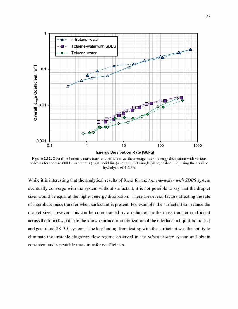
Figure 2.12. Overall volumetric mass transfer coefficient vs. the average rate of energy
dissipation with various solvents for the size 600 LL-Rhombus (light, solid line) and the
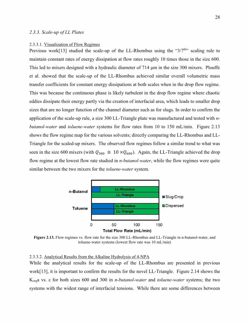
LL-Triangle (dark, dashed line) using the alkaline hydrolysis of 4-NPA ........................ 27 Figure 2.13. Flow regimes vs. flow rate for the size 300 LL-Rhombus and LL-Triangle in n-
butanol-water, and toluene-water systems (lowest flow rate was 10 mL/min) ................ 28 Figure 2.14. Overall volumetric mass transfer coefficient vs. average rate of energy dissipation
for n-butanol-water (dark blue) and toluene-water (light green) systems with the size 600
(○) and 300 (□) LL-Triangle mixer using the alkaline hydrolysis of 4-NPA ................... 29 Figure 2.15. Overall volumetric mass transfer coefficient vs. the average rate of energy
dissipation for n-butanol-water (light) and (b) toluene-water (dark) systems with the size
300 LL-Rhombus and LL-Triangle using the alkaline hydrolysis of 4-NPA ................... 30
Figure 3.1. FlowPlate® Lab SZ Mix-Then-Reside (MTR) reactor plates manufactured by Ehrfeld
Mikrotechnik BTS size 600 (left) and 300 (right) ............................................................ 37
Figure 3.2. FlowPlate® Lab, A6, and A5 Systems (from left to right) ......................................... 38 Figure 3.3. FlowPlate® A6 Reactor system manufactured by Ehrfeld Mikrotechnik BTS (left,
back), single reactor plate (left, front), and an open MTR (SZ) reactor plate revealing the
channels (right) ................................................................................................................. 42 Figure 3.4. CAD drawings of the 320 RTC plate ......................................................................... 42
Figure 3.5. 3D representations of TG (left) and SZ (right) mixing elements ............................... 44 Figure 3.6. Schematic of heat transfer experimental setup ........................................................... 45 Figure 3.7. Reaction network for the synthesis of methyl 2-oxobutanoate (DMO) ..................... 46
x
Figure 3.8. Thermal circuit diagram between heat transfer fluid and process fluid; highlighting
potentially significant external resistances in red ............................................................. 48 Figure 3.9. Pressure loss and friction factor vs. Re for the 320b RTC ......................................... 49
Figure 3.10. Temperature vs. internal water flow rate for various conditions for the 320B-RTC 49 Figure 3.11. Total thermal resistance vs. 1/Re .............................................................................. 50 Figure 3.12. Nusselt number (experimental and predicted) vs. Reynolds number for the 320b
RTC ................................................................................................................................... 51 Figure 3.13. Effect of multi-injection for Grignard Reaction ....................................................... 53
Figure 3.14. Yield vs. flow rate in the 315 and 350 plates at various temperatures ..................... 54 Figure 3.15. (a) Average Grignard reaction yield (at -15 °C) vs. mixer specific area for heat
transfer, and (b) Grignard reaction yield (at -15 °C) vs. specific energy dissipation rate
(u3/dh) ................................................................................................................................ 55 Figure 3.16. Fourth Damköhler number at different heat generation rates as a function of the
sized-up hydraulic diameter and with U = 2200 W/(m2 K) and |T-Ttf| = 10 K ................. 57

xi
List of Tables
Table 2.1. Physical Properties of Solvents at 23 ºC ...................................................................... 13 Table 2.2. Size 600 micro-mixer geometries studied and number of mixers per plate-reactor with
a dh of 286 μm (width of 0.2 mm, depth of 0.5 mm) ........................................................ 15 Table 2.3. Size 300 micro-mixer geometries studied and number of mixers per plate-reactor with
a dh of 714 μm (width of 0.5 mm, depth of 1.25 mm) ...................................................... 15
Table 2.4. n-butanol-water flow regimes at various flow ranges (using interval notation) for the
size 600 (a) Sickle; (b) LL- Rhombus; (c) LL-Triangle ................................................... 17 Table 2.5. Toluene-water flow regimes at various flow ranges (using interval notation) for the
size 600 (a) Sickle; (b) LL- Rhombus; (c) LL-Triangle; (d) LL-Empty........................... 19 Table 2.6. Flow regimes at various flow ranges (using interval notation) for the size 600 LL-
Rhombus (a) and LL-Triangle (b) with toluene-water with SDBS surfactant .................. 25
Table 3.1. FlowPlate® sizes and production capacities................................................................. 37
Table 3.2. Reactor plate properties ............................................................................................... 43 Table 3.3. Physical properties of water at various temperatures [28] ........................................... 46

1
1. Introduction
1.1. Background
In pharmaceutical and fine chemical industries, there has been an increased interest in the
development of continuous flow processes in micro-reactors, over batch-wise systems [1–4]. This
trend stems from the relative ease in scale-up of flow systems, the potential for process
intensification due to operation at small scales, increased process safety in handling hazardous
materials, and the increased rates of transport.
As there are several stages in the development of new pharmaceutical chemicals, each requiring
increased campaign sizes [5,6], micro-reactors offer added flexibility in their scale-up than in batch
systems. Since it is possible to maintain mixing properties for single-phase [7] and multi-phase
[8] systems at a given rate of energy dissipation (ε), the channel size can be increased such that a
given increase in flow will yield the same ε. As a proof of concept, this strategy was employed
for a mixing-limited lithiation reaction where similar yields were obtained in separate reactors,
one with double the hydraulic diameter of the other, where over 2 tons of isolated material was
produced [3].
Process intensification is a clear advantage of micro-reactors [3,4,7,9–12]. With smaller channel
sizes, it is possible to operate at higher pressures, and therefore temperatures (due to increased
boiling point of the solvent). Higher temperatures allow for faster reaction kinetics, while higher
pressures give higher gas concentrations in gas-liquid systems. These factors lead micro-reactors
to increase the space-time yield by orders of magnitude when compared to batch reactors [13].
Additionally, it is possible to perform hazardous reactions, such as oxidations with pure O2 [14,15],
in a safer manner. In flow, multistep reactions involving highly explosive intermediates can be
performed continuously without the isolation of dangerous materials, such as diazo compounds
[12,16,17].
The last main advantage to micro-reactor technology is the improved transport phenomena with
smaller length scales. Micro-reactors offer a variety of mixing strategies for single phase or
multiphase; either through passive [18] (e.g., obstacles, curvature in the channels, etc.) or active
[19,20] (e.g., pulsating flow, ultrasound, magnetic stirrers, etc.) mixing techniques. Various
passive mixing structures have been studied extensively in single-phase [3,4,7,9–12] and multi-
2
phase systems [2,12,18,21,22] and have been found to have mixing times up to 2 orders of
magnitude faster than larger scale reactors [10]. In addition to the improved hydrodynamics,
micro-channels also have intrinsically higher surface-area-to-volume ratios for heat transfer which
can exchange sufficient heat for highly exothermic/endothermic reactions. In multi-phase systems,
the small channel sizes (and mixing strategies previously mentioned) allow for smaller droplets to
form, increasing the interfacial area available for mass exchange [18,23].
1.2. Motivation and Research Topics
While there are many different micro-reactor systems available commercially from companies
such as ThalesNano Inc, Ehrfeld Mikrotechnik BTS, Syrris Ltd, Vapourtec Ltd, etc., it is important
to use the proper system for a given application. For this reason, Plouffe et al. [24] developed a
“toolbox” which could be used to select a reactor type effectively. Reactive systems were divided
into reaction types based on their kinetics/thermal requirements, as well as the phase system
(homogenous, liquid-liquid, liquid-gas, gas-solid, etc.). The objective of this work is to study and
better define the transport phenomena for certain “tools” in the toolbox; namely mixer geometries
for fast (type A) liquid-liquid reactions, and heat transfer properties of micro-reactors for
homogenous systems.
1.3. Thesis Outline
Section 2 investigates several micro-mixer geometries which were developed in order to improve
the mixing efficiency for fast liquid-liquid reactions based on previous work by Plouffe et al. [18].
It has been published under the title “Microreactor mixing-unit design for fast liquid-liquid
reactions”. Various flow regimes (slug flow, parallel flow, and drop flow) were investigated
visually and with a test reaction, the two-phase hydrolysis of 4-nitrophenyl acetate in sodium
hydroxide solution, to analytically measure the overall volumetric mass transfer coefficients
(Korga) as a function of the average rate of energy dissipation (ε) for the different mixer designs
and flow regimes. These were compared with different solvent-pairs to consider the effect of
interfacial tension on the onset of drop flow.
Section 3 was focused on single-phase heat transfer in micro-channels, and the results will be
submitted for publication under the title “Investigation of Overall and Localized Heat Transfer
in Curved Micro-Channel Reactor Systems”. Using the FlowPlate® system by Ehrfeld

3
Mikrotechnik BTS, heat transfer experiments with a reactive and non-reactive systems were
performed. For a range of Reynolds numbers between 400-2000, a Gnielinski-type model was
used to fit the Nusselt number results in the non-reactive system. In the reactive system, the fast
and highly exothermic synthesis of methyl 2-oxobutanoate, using dimethyl-oxalate and the
Grignard reagent ethylmagnesium chloride, was studied. Due to the selectivity’s temperature
dependence, this proved to be a sensitive test reaction to differentiated the localized heat transfer
characteristics in various reactor sizes, injection modes, geometries, and wall materials. Lastly,
four reaction systems were analyzed in a case study based on the fourth Damköhler number to
calculate the maximum channel size that can remove sufficient heat to avoid a hotspot from the
enthalpy of reaction.
In conclusion, the each of the two sections aid in the selection and sizing of a micro-reactor system
for mass-transfer-limited liquid-liquid systems or systems which require significant heat transfer,
as summarized in section 4. Recommendations for future work are also provided in order to extend
the scope of this project.
1.4. Other Considerations in the Study of Heat Transfer in Microreactors
In the literature for heat transfer studies in micro-reactors and micro-channels, there is no strong
consensus regarding the application of conventional, macro-scale correlations to micro-scale
channels, as there is significant variance in the observed results [25–28]. Steinke and Kandlikar
considered three key, underlying causes specific to research in micro-reactor systems responsible
for the differences in various investigations [25,28]. These were taken into account when choosing
the operating conditions for Section 3:
i) Thermal Entrance Length: Micro-channels generally have shorter relative lengths
(𝑙/𝐷ℎ) that are often employed to reduce the total pressure drop. Both the
hydrodynamic and thermally developing regions can represent a larger fraction of the
total length, and the local heat transfer coefficient is higher in this region than the fully
developed region [25]. The fluid is often considered to be thermally developed after a
certain length, 𝐿𝑡, defined by equation (1.1) for laminar flow in a straight channel [25].
Where 𝑅𝑒 is the Reynolds number (ratio of inertial to viscous forces), and 𝑃𝑟 is the
Prandtl number (ratio of momentum to thermal diffusivities). The value of the constant,
4
c, often ranges between 0.05 and 0.1 [25], but was shown to be closer to 0.02 when
rectangular ducts with aspect ratios (𝛼) of 10 or more were used [29]. This leads to the
thermal entrance length accounting for between 5-15% of the overall reactor length for
the conditions studied, where the channel’s aspect ratio was 10.
𝐿𝑡
𝐷ℎ= 𝑐𝑅𝑒𝑃𝑟 (1.1)
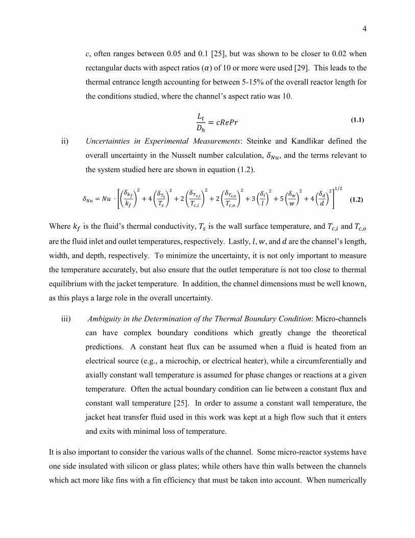
ii) Uncertainties in Experimental Measurements: Steinke and Kandlikar defined the
overall uncertainty in the Nusselt number calculation, 𝛿𝑁𝑢, and the terms relevant to
the system studied here are shown in equation (1.2).
𝛿𝑁𝑢 = 𝑁𝑢 ∙ [(𝛿𝑘𝑓
𝑘𝑓
)
2
+ 4 (𝛿𝑇𝑠
𝑇𝑠
)
2
+ 2 (𝛿𝑇𝑐,𝑖
𝑇𝑐,𝑖
)
2
+ 2 (𝛿𝑇𝑐,𝑜
𝑇𝑐,𝑜
)
2
+ 3 (𝛿𝑙
𝑙)
2
+ 5 (𝛿𝑤
𝑤)
2
+ 4 (𝛿𝑑
𝑑)
2
]
1/2
(1.2)
Where 𝑘𝑓 is the fluid’s thermal conductivity, 𝑇𝑠 is the wall surface temperature, and 𝑇𝑐,𝑖 and 𝑇𝑐,𝑜
are the fluid inlet and outlet temperatures, respectively. Lastly, 𝑙, 𝑤, and 𝑑 are the channel’s length,
width, and depth, respectively. To minimize the uncertainty, it is not only important to measure
the temperature accurately, but also ensure that the outlet temperature is not too close to thermal
equilibrium with the jacket temperature. In addition, the channel dimensions must be well known,
as this plays a large role in the overall uncertainty.
iii) Ambiguity in the Determination of the Thermal Boundary Condition: Micro-channels
can have complex boundary conditions which greatly change the theoretical
predictions. A constant heat flux can be assumed when a fluid is heated from an
electrical source (e.g., a microchip, or electrical heater), while a circumferentially and
axially constant wall temperature is assumed for phase changes or reactions at a given
temperature. Often the actual boundary condition can lie between a constant flux and
constant wall temperature [25]. In order to assume a constant wall temperature, the
jacket heat transfer fluid used in this work was kept at a high flow such that it enters
and exits with minimal loss of temperature.
It is also important to consider the various walls of the channel. Some micro-reactor systems have
one side insulated with silicon or glass plates; while others have thin walls between the channels
which act more like fins with a fin efficiency that must be taken into account. When numerically

5
solving heat transfer problems in reactors with walls between the channels, the walls can often be
considered one dimensional for the purposes of conduction [30].
1.5. Nomenclature
Symbols [𝑈𝑛𝑖𝑡𝑠]
General
𝑎 Specific area (single phase) or specific interfacial area (biphasic) [𝑚2/𝑚3] 𝑐 Empirical constant for calculation of thermal developing region [−] 𝑑 Contraction depth [𝑚] 𝐷ℎ Hydraulic diameter at contraction (2𝑤𝑑/(𝑤 + 𝑑)) [𝑚] 𝑘 Thermal conductivity [𝑊/(𝑚 𝐾)] 𝐾𝑜𝑟𝑔 Overall convective mass transfer coefficient (m/s) [𝑚/𝑠]
𝑙 Reactor Length [𝑚] 𝐿𝑡 Length of thermal developing region [𝑚] 𝑁𝑢 Nusselt Number [−] 𝑃𝑟 Prandtl Number [−] 𝑅𝑒 Reynolds Number [−] 𝑇 Temperature [°𝐶 𝑜𝑟 𝐾] 𝑤 Contraction width [𝑚]
Greek Symbols
𝛼 Aspect ratio (w/d) [−] 𝛿𝑥 Uncertainty with respect to value of any parameter, x [−] 휀 Average rate of energy dissipation (∆𝑃 𝜌𝜏⁄ ) [𝑚2/𝑠3]
Subscript
𝑐 Cold stream
𝑓 Fluid
𝑖 Measured at inlet
𝑜 Measured at outlet
𝑠 Conditions at the wall surface
1.6. References
[1] N.-T. Nguyen, Z. Wu, Micromixers—a review, J. Micromechanics Microengineering. 15
(2005) R1–R16. doi:10.1088/0960-1317/15/2/R01.
[2] M.N. Kashid, L. Kiwi-Minsker, Microstructured Reactors for Multiphase Reactions: State
of the art, Ind. Eng. Chem. Res. 48 (2009) 6465–6485. doi:10.1021/ie8017912.
[3] N. Kockmann, M. Gottsponer, D.M. Roberge, Scale-up concept of single-channel
microreactors from process development to industrial production, Chem. Eng. J. 167
(2011) 718–726. doi:10.1016/j.cej.2010.08.089.

6
[4] V. Kumar, M. Paraschivoiu, K.D.P. Nigam, Single-phase fluid flow and mixing in
microchannels, Chem. Eng. Sci. 66 (2011) 1329–1373. doi:10.1016/j.ces.2010.08.016.
[5] L. Malet-Sanz, F. Susanne, Continuous flow synthesis. a pharma perspective, J. Med.
Chem. 55 (2012) 4062–4098. doi:10.1021/jm2006029.
[6] N. Kockmann, M. Gottsponer, B. Zimmermann, D.M. Roberge, Enabling continuous-flow
chemistry in microstructured devices for pharmaceutical and fine-chemical production,
Chem. - A Eur. J. 14 (2008) 7470–7477. doi:10.1002/chem.200800707.
[7] C.P. Holvey, D.M. Roberge, M. Gottsponer, N. Kockmann, A. Macchi, Pressure drop and
mixing in single phase microreactors: Simplified designs of micromixers, Chem. Eng.
Process. Process Intensif. 50 (2011) 1069–1075. doi:10.1016/j.cep.2011.05.016.
[8] P. Plouffe, M. Bittel, J. Sieber, D.M. Roberge, A. Macchi, On the scale-up of micro-
reactors for liquid–liquid reactions, Chem. Eng. Sci. 143 (2016) 216–225.
doi:10.1016/j.ces.2015.12.009.
[9] P. Plouffe, R. Anthony, A. Donaldson, D.M. Roberge, N. Kockmann, A. Macchi,
Transport Phenomena in Two-Phase Liquid-Liquid Micro-Reactors, in: ASME 2012 10th
Int. Conf. Nanochannels, Microchannels, Minichannels, Rio Grande, Puerto Rico, 2012.
http://proceedings.asmedigitalcollection.asme.org/proceeding.aspx?articleid=1719073
(accessed August 19, 2014).
[10] M. Kashid, A. Renken, L. Kiwi-Minsker, Mixing efficiency and energy consumption for
five generic microchannel designs, Chem. Eng. J. 167 (2011) 436–443.
doi:10.1016/j.cej.2010.09.078.
[11] L. Falk, J.M. Commenge, Performance comparison of micromixers, Chem. Eng. Sci. 65
(2010) 405–411. doi:10.1016/j.ces.2009.05.045.
[12] V. Hessel, D. Kralisch, N. Kockmann, T. Noel, Q. Wang, Novel Process Windows for
Enabling, Accelerating, and Uplifting Flow Chemistry, ChemSusChem. 6 (2013) 746–
789. doi:10.1002/cssc.201200766.
[13] V. Hessel, Process windows - gate to maximizing process intensification via flow
chemistry, Chem. Eng. Technol. 32 (2009) 1655–1681. doi:10.1002/ceat.200900474.
[14] B. Gutmann, P. Elsner, D.P. Cox, U. Weigl, D.M. Roberge, C.O. Kappe, Toward the
synthesis of noroxymorphone via aerobic palladium-catalyzed continuous flow n-
demethylation strategies, ACS Sustain. Chem. Eng. 4 (2016) 6048–6061.
doi:10.1021/acssuschemeng.6b01371.
[15] C.A. Hone, D.M. Roberge, C.O. Kappe, The Use of Molecular Oxygen in Pharmaceutical
Manufacturing: Is Flow the Way to Go?, ChemSusChem. (2016) 1–11.
doi:10.1002/cssc.201601321.
[16] L.J. Martin, A.L. Marzinzik, S. V. Ley, I.R. Baxendale, Safe and reliable synthesis of
7
diazoketones and quinoxalines in a continuous flow reactor, Org. Lett. 13 (2011) 320–323.
doi:10.1021/ol1027927.
[17] X. Zhang, S. Stefanick, F.J. Villani, Application of Microreactor Technology in Process
Development, Org. Process Res. Dev. 8 (2004) 455–460. doi:10.1021/op034193x.
[18] P. Plouffe, D.M. Roberge, A. Macchi, Liquid–liquid flow regimes and mass transfer in
various micro-reactors, Chem. Eng. J. 300 (2016) 9–19. doi:10.1016/j.cej.2016.04.072.
[19] S.S. Mongeon, D.M. Roberge, M. Bittel, P. Elsner, A. Macchi, Liquid–Liquid Mass
Transfer in an Oscillatory-Flow Mesoscale Coil Reactor without Baffles, Org. Process
Res. Dev. (2016) acs.oprd.5b00356. doi:10.1021/acs.oprd.5b00356.
[20] H. Monnier, A.M. Wilhelm, H. Delmas, Effects of ultrasound on micromixing in flow
cell, Chem. Eng. Sci. 55 (2000) 4009–4020. doi:10.1016/S0009-2509(00)00067-1.
[21] L. Ducry, D.M. Roberge, Controlled Autocatalytic Nitration of Phenol in a Microreactor,
Angew. Chemie - Int. Ed. 44 (2005) 7972–7975. doi:10.1002/anie.200502387.
[22] G. Dummann, U. Quittmann, L. Gröschel, D.W. Agar, O. Wörz, K. Morgenschweis, The
Capillary-Microreactor: A New Reactor Concept for the Intensification of Heat and Mass
Transfer in Liquid-Liquid Reactions, Catal. Today. 79–80 (2003) 433–439.
doi:10.1016/S0920-5861(03)00056-7.
[23] P. Plouffe, D.M. Roberge, J. Sieber, M. Bittel, A. Macchi, Liquid–liquid mass transfer in a
serpentine micro-reactor using various solvents, Chem. Eng. J. 285 (2016) 605–615.
doi:10.1016/j.cej.2015.09.115.
[24] P. Plouffe, A. Macchi, D.M. Roberge, From Batch to Continuous Chemical Synthesis—A
Toolbox Approach, Org. Process Res. Dev. (2014). doi:10.1021/op5001918.
[25] S. Kandlikar, S. Garimella, D. Li, S. Colin, M.R. King, Heat Transfer and Fluid Flow in
Minichannels and Microchannels, 2nd ed., Elsevier Ltd., Kidlington, Oxford, 2014.
doi:10.1016/B978-0-08-098346-2.00003-X.
[26] F.P. Incropera, D.P. DeWit, T.L. Bergman, A.S. Lavine, Fundamentals of Heat and Mass
Transfer, 7th ed., John Wiley & Sons, Inc., Jefferson City, 2011.
[27] G.L. Morini, Single-phase convective heat transfer in microchannels: A review of
experimental results, Int. J. Therm. Sci. 43 (2004) 631–651.
doi:10.1016/j.ijthermalsci.2004.01.003.
[28] M.E. Steinke, S.G. Kandlikar, Single-phase liquid heat transfer in microchannels, in: 3rd
Int. Conf. Microchannels Minichannels, 2005. doi:10.1115/ICMM2005-75114.
[29] P.S. Lee, S. V. Garimella, Thermally developing flow and heat transfer in rectangular
microchannels of different aspect ratios, Int. J. Heat Mass Transf. 49 (2006) 3060–3067.
doi:10.1016/j.ijheatmasstransfer.2006.02.011.

8
[30] P.S. Lee, S. V. Garimella, D. Liu, Investigation of heat transfer in rectangular
microchannels, Int. J. Heat Mass Transf. 48 (2005) 1688–1704.
doi:10.1016/j.ijheatmasstransfer.2004.11.019.
9
2. Micro-Reactor Mixing-Unit Design for Fast Liquid-Liquid Reactions
Eric Mielke,a Dominique M. Roberge,b and Arturo Macchia
a, Centre for Catalysis Research and Innovation, Department of Chemical and Biological Engineering, University
of Ottawa, K1N 6N5 Ottawa, Canada.
b, Chemical Manufacturing Technologies, Lonza AG, CH-3930 Visp, Switzerland.
This manuscript has been published J. Flow Chem. 2016, 6(3), 279–287
ABSTRACT
Based on previous work studying complex micro-reactors, it was desired to further improve the
mixing efficiency by varying the mixing unit design for fast liquid-liquid reactions. Different flow
regimes were studied; including slug flow, parallel flow, and drop flow. The two-phase hydrolysis
of 4-nitrophenyl acetate in sodium hydroxide solution was used to evaluate the overall volumetric
mass transfer coefficients (Korga) as a function of the average rate of energy dissipation (ε) for each
micro-reactor design and all flow regimes. The liquid-liquid systems investigated used n-butanol
or toluene as the organic phase solvent and a 0.5 M NaOH aqueous solution. The use of surfactant
was also investigated with the toluene-water system. All micro-reactor geometry designs were
based on contraction-expansion repeating units with asymmetric obstacles to aid the breakup of
slugs, and desynchronize the recombination of split streams. The investigated designs were chosen
to avoid the formation of the parallel flow regime; contrary to curvature-based mixing-unit
designs. The micro-reactor design can then be optimized to reduce the ε required to reach drop
flow, since Korga has been found to be constant at equal ε for a given solvent system in this flow
regime, regardless of the reactor selection. Additionally, the “3/7th” scale-up rule was applied and
confirmed with the LL-Triangle mixer. It was found that for low interfacial-tension systems (i.e.,
n-butanol-water), the onset of drop flow occurred at a lower ε for the LL-Triangle mixer when
compared with the Sickle or LL-Rhombus mixers.
Keywords: Micro-reactor, Liquid-liquid reaction, Mass transfer, Mixing, Slug- Parallel- drop- and
dispersed-flow
10
2.1. Introduction
In the past 10 years, flow technologies have become an ever more popular field of study in the fine
chemical and pharmaceutical industries[1]. Continuous-flow is an attractive alternative to
conventional batch processing with a number of benefits; namely process intensification via higher
operating pressures and temperatures, and the increased surface-to-volume ratios involved with
miniaturization (micro-reactors). While these advantages have been studied extensively in single
phase systems[1–7], much of the research on multiphase systems[7–10] involves slug or parallel
flow regimes where interphase mass transfer is relatively slow.
Previous work[11–17] studied the effects of using passive micro-mixing structures to increase the
mass transfer rate between two immiscible phases in flow ranges that would have otherwise been
in the slug flow regime for a similar-sized capillary reactor. A micro-mixer-based reactor was
shown to be well suited for fast liquid-liquid reactions[14] (i.e., mass or heat transfer limited with
reaction times in the millisecond to second range). Plouffe et al. further investigated the
dependency of flow regimes on solvent-pair selection[12] and micro-mixer structure[11]. It was
found that systems with low interfacial tension could transition from slug, to parallel, and then to
drop flow regime with increasing flow rates; whereas systems with higher interfacial tension would
not favour the parallel flow regime to form. Slug flow was shown to have an increasing overall
volumetric mass transfer coefficient (Korga) with flow while the transition from slug to parallel
flow would cause a significant drop in Korga due to the decreased surface area available for
interphase mass transfer. The drop flow regime was found to have the highest Korga and would
only increase with flow. In the study involving various reactor geometries[11], it was also shown
that Korga is only a function of the average rate of energy dissipation (ε) and solvent-pair once the
flow has reached the drop flow regime, independent of reactor geometry, indicating that an ideal
micro-mixer for fast liquid-liquid reactions must achieve drop flow at the lowest possible ε.
While investigating various mechanisms of mixing in micro-mixer, it was found that curvature-
based micro-mixers could allow for the formation of a parallel flow regime while this was avoided
in obstacle-based micro-mixers. Parallel flow is caused by the difference in densities between the
two phases; where the denser phase would be forced to the outer edge of the curve due to
centrifugal forces. When an increased rate of interphase mass transfer is desired, parallel flow

11
should be avoided due to the reduced internal circulation in each phase, along with the reduced
specific area available for mass transfer when compared with slug or drop flow regimes.
This work investigates the LL-Rhombus and LL-Triangle micro-mixers, which are designed as
modifications to the Sickle mixer with reduced curvature while keeping a contraction-expansion
and obstacle as primary modes of energy dissipation. The only difference between the LL-
Rhombus and LL-Triangle (which is shown in Figure 2.1) is the obstacle shape; where the rhombus
has a more hydrodynamic shape with a cutting angle of 42°, whereas the triangle has an abrupt
wall at a 90° angle towards the flow direction. The use of an obstacle with an angle greater than
90° and reverting flow in the opposite direction[18] was avoided as it could generate parallel flow
under some conditions[11]. Another LL mixer without obstacle was tested to confirm that an
obstacle is beneficial for more efficient mixing than solely relying on the contraction-expansion.
Figure 2.1. 3D visualization of the LL-Rhombus mixing element
2.2. Experimental
The experimental and HPLC analytical methods used are similar to those used in previous work
by Plouffe et al.[11–13] with differences in the specific reactor plates and solvents used. The
specifications for the specific reactor plates can be found in Table 2.2 and Table 2.3.
2.2.1. Equipment Setup
2.2.1.1. Size 600 Experimental Setup
For the size 600 tests, the Ehrfeld MMRS was used with Lonza FlowPlate® Lab reactors made
from either stainless steel 316 or Hastelloy C22™. The setup can be seen in Figure 2.2. The system
was fed the aqueous and organic solutions using two Syrdos (HiTec Zang) pumps with 5 or 2.5
mL syringes. Endress-Hauser Coriolis flow meters were used to measure the mass flow rates, and
25 or 6 bar Wika M-11 pressure transducers measured the pressure difference from the inlet to the

12
outlet of the reactor. The system was kept at ambient temperatures using a Huber Ministat 125
thermal bath.
Figure 2.2. Size 600 micro-reactor experimental setup
2.2.1.2. Size 300 Experimental Setup
The setup for the size 300 scaled-up mixers was identical for the size 600, except Ismatec Reglo-
Z gear pumps were used for the higher flow rates.
2.2.1.3. Solvent Systems
The physical properties of the aqueous and organic phases used can be found in Table 2.1. For
tests with sodium dodecylbenzene sulfonate (SDBS), 0.018 g of SDBS was added to 1 liter of 0.5
M NaOH solution. This was an arbitrary amount chosen after visually testing the mixing of
different concentrations of SDBS in toluene-water solutions. The SDBS was added to the aqueous
phase to avoid the risk of any reaction between the surfactant and the 4-NPA reactant before
entering the reactor. The feed solution was kept mixed to ensure the SDBS concentration remained
constant during the experiment.

13
Table 2.1. Physical Properties of Solvents at 23 ºC
Fluid
𝝆
[𝐤𝐠/𝐦𝟑] 𝝁
[𝐦𝐏𝐚 ∙ 𝐬]
Interfacial
tension with
water [𝐦𝐍/𝐦]
Solubility
in water
[𝐦𝐨𝐥%]
Toluene[19–21] 862 0.552 35.4 0.01
n-Butanol[19–21] 806 2.571 1.8 1.88
0.5 M NaOH in water [22] 1020 1.124 - -
2.2.2. Test Reaction: Alkaline Hydrolysis of 4-Nitrophenyl Acetate
The two-phase alkaline hydrolysis of 4-nitrophenyl acetate (4-NPA, Scheme 1) was used to
analytically measure the overall volumetric mass transfer coefficient of a given mixer. It has been
shown that the kinetics have an intrinsic rate constant of 14.0 L/(mol s) for a second order
reaction[23–25]. Using a 0.5 mol/L concentration of NaOH in water and 0.05 mol/L of 4-NPA in
whichever organic solvent was being tested allowed for a 10:1 molar ratio of NaOH to 4-NPA
(due to equal volumetric flow rates), causing pseudo-first order reaction conditions. In addition,
the product, 4-nitrophenolate would turn the alkaline aqueous phase yellow when present, allowing
for a visual distinction of the extent of reaction. Flow visualizations were taken using the reactor
sight glass with a Nikon D40x “kit” camera fitted with an AF-S DX Zoom-Nikkor 18–55mm
𝑓/3.5–5.6 G ED II lens and the flow regimes were noted.
A single experiment consisted of 7-9 flow rates being tested after flushing the system with
reactants for 5 minutes at 10 mL/min. Once a new flow rate was set, the system was left at least
three residence times to reach steady state before taking the sample. If three residence times lasts
less than two minutes, two minutes was left between the change of flow rate and sampling to allow
the operator sufficient time to prepare the next sample or take photographs of the flow regime if
required. The sample time for a given flow rate was the larger of three residence times or 5
seconds. Samples were taken at the outlet into a quench solution; an agitated mixture of
acetonitrile, water, and acetic acid that homogenized and neutralized the reactor effluent. The
Scheme 1. Alkaline hydrolysis of 4-nitrophenyl acetate

14
quench solution composition was based on the particular solvent since different amounts of
acetonitrile are required to homogenize the outlet sample. The samples were analyzed with an HP
Agilent 1100 series HPLC system with a 250mm × 4.6mm i.d. Agilent Zorbax SB-C8 at room
temperature.
2.3. Results and Discussion
All four geometries studied, and the specifications of their reactor plates can be found in Table
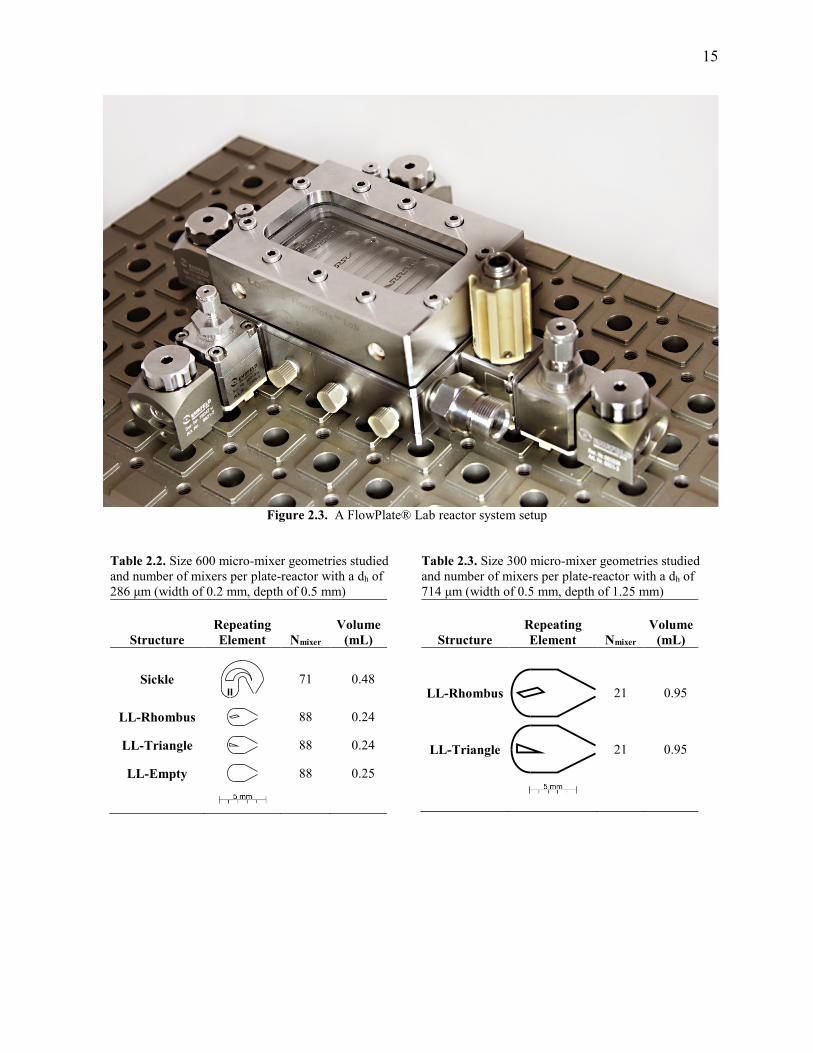
2.2. The micro-mixers were manufactured as exchangeable plates onto a FlowPlate® Lab (size
A7, seen in Figure 2.3) reactor unit, which allows for visualization of the flow regimes through a
glass viewport. Size 600 micro-mixers have a hydraulic diameter measured at the narrowest
contraction, dh, of 286 μm (width of 0.2 mm, depth of 0.5 mm). Scaled-up versions of the LL-
Rhombus and LL-Triangle were also studied, and the specifications of these reactor plates can be
found in Table 2.3. The size 300 mixers were designed with a dh of 714 μm (width of 0.5 mm,
depth of 1.25 mm); a diameter that allows for roughly a 10x scale-up of flow rate for constant
energy dissipation[13]. An example of both reactor plate scales can be seen in Figure 2.4. Note
that the term reactor plate refers to an entire reactor with multiple micro-mixers, while mixer or
mixing unit relates to a particular mixing element.
15
Figure 2.3. A FlowPlate® Lab reactor system setup
Table 2.2. Size 600 micro-mixer geometries studied
and number of mixers per plate-reactor with a dh of
286 μm (width of 0.2 mm, depth of 0.5 mm)
Structure
Repeating
Element Nmixer
Volume
(mL)
Sickle
71 0.48
LL-Rhombus
88 0.24
LL-Triangle
88 0.24
LL-Empty
88 0.25
Table 2.3. Size 300 micro-mixer geometries studied
and number of mixers per plate-reactor with a dh of
714 μm (width of 0.5 mm, depth of 1.25 mm)
Structure
Repeating
Element Nmixer
Volume
(mL)
LL-Rhombus
21 0.95
LL-Triangle
21 0.95
16
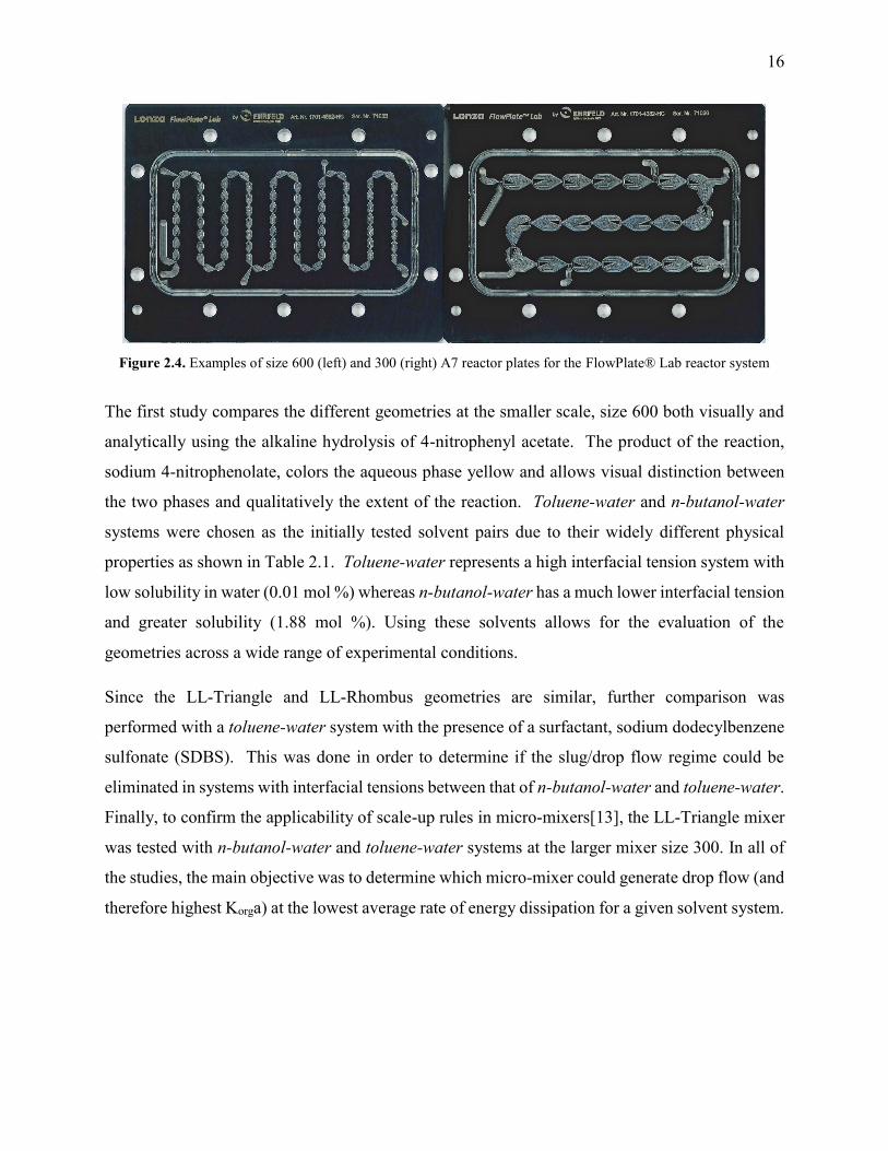
Figure 2.4. Examples of size 600 (left) and 300 (right) A7 reactor plates for the FlowPlate® Lab reactor system
The first study compares the different geometries at the smaller scale, size 600 both visually and
analytically using the alkaline hydrolysis of 4-nitrophenyl acetate. The product of the reaction,
sodium 4-nitrophenolate, colors the aqueous phase yellow and allows visual distinction between
the two phases and qualitatively the extent of the reaction. Toluene-water and n-butanol-water
systems were chosen as the initially tested solvent pairs due to their widely different physical
properties as shown in Table 2.1. Toluene-water represents a high interfacial tension system with
low solubility in water (0.01 mol %) whereas n-butanol-water has a much lower interfacial tension
and greater solubility (1.88 mol %). Using these solvents allows for the evaluation of the
geometries across a wide range of experimental conditions.
Since the LL-Triangle and LL-Rhombus geometries are similar, further comparison was
performed with a toluene-water system with the presence of a surfactant, sodium dodecylbenzene
sulfonate (SDBS). This was done in order to determine if the slug/drop flow regime could be
eliminated in systems with interfacial tensions between that of n-butanol-water and toluene-water.
Finally, to confirm the applicability of scale-up rules in micro-mixers[13], the LL-Triangle mixer
was tested with n-butanol-water and toluene-water systems at the larger mixer size 300. In all of
the studies, the main objective was to determine which micro-mixer could generate drop flow (and
therefore highest Korga) at the lowest average rate of energy dissipation for a given solvent system.

17
2.3.1. All Geometries Comparison
2.3.1.1. Visualization of Flow Regimes
In studying multi-phase mixing in micro-reactors, it is important first to investigate the flow
regimes that occur[11,12,14]. Previous work distinguished between three distinct flow regimes:
slug, parallel, and drop flow[12]. In the present study, combinations of these flow regimes were
observed at different flow rates in each of the reactors studied. In addition, dispersed flow is
defined to be a subset of drop flow where droplets are too small to be resolved visually and are
seen as an emulsion. It is important to note that this is not a meaningful change in flow regime,
but rather a qualitative point that can be observed visually. The flow regimes in the n-butanol-
water systems for size 600 reactors are shown in Table 2.4 with the flow regime map in Figure
2.5.
Table 2.4. n-butanol-water flow regimes at various flow ranges (using interval notation) for the size 600 (a) Sickle; (b) LL-
Rhombus; (c) LL-Triangle
Flow Regime
Visualization [Flow Rate (
mL
min)]
(a) Sickle
Parallel/Drop
[1.0 – 4.0]
Parallel/Dispersed
(4.0 – 7.0]
Dispersed
(7.0 – 20.0]
(c) LL-Triangle
Dropa
[1.0 – 1.5]
Dispersed
(1.5 – 20.0]
Flow Regime
Visualization [Flow Rate (
mL
min)]
(b) LL-Rhombus
Slug/Drop
[1.0 – 3.0]
Drop
(3.0 – 7.0]
Dispersed
(7.0 – 20.0]
a Video of flow regime shown in Supplementary Material V.1.

18
Figure 2.5. Flow regimes vs. flow rate for various size 600 geometries in an n-butanol-water system
In the Sickle reactor plate, parallel flow was observed in some form from 1.0 to 7.0 mL/min, while
both LL mixers avoided this flow regime due to the minimization of curvature in the design. In
fact, the LL-Triangle achieved drop flow at flow rates as low as 1.0 mL/min, whereas the LL-
Rhombus required at least 3.0 mL/min.
Table 2.5 shows the flow regimes observed in the toluene-water system for all four geometries
studied, and Figure 2.6 shows the flow regime map for the Sickle, LL-Rhombus, and LL-Triangle.
The LL-empty was not included in the map as it is not an obstacle-based micro-mixer, and
therefore has different flow regimes than the other mixers, as depicted in Table 2.5.

19
Table 2.5. Toluene-water flow regimes at various flow ranges (using interval notation) for the size 600 (a) Sickle; (b) LL-
Rhombus; (c) LL-Triangle; (d) LL-Empty
Flow Regime
Visualization [Flow Rate (
mL
min)]
(a) Sickle
Slug
[1.0 – 3.6]
Slug/Drop
(3.6 – 8.0]
Drop
(8.0 – 20.0]
(c) LL-Triangle
Slug/Dropb
[1.0 – 10.0]
Dispersedb
(10.0 – 20.0]
Flow Regime
Visualization [Flow Rate (
mL
min)]
(b) LL-Rhombus
Slug
[1.0]
Slug/Drop
(1.0 – 10.0]
Dispersed
(10.0 – 20.0]
(d) LL-Empty
Slug
[1.0]
Slug/Jet/Drop
(1.0 – 5.0]
Jet/Drop
(5.0 – 20.0]
b Video of flow regime shown in Supplementary Material V.2.
Figure 2.6. Flow regimes vs. flow rate for various size 600 geometries in a toluene-water system
As the toluene-water system has a greater interfacial tension than n-butanol-water, it is expected
that higher flow rates are required for the onset of drop flow. In addition, parallel flow was not
20
likely to be observed in any micro-mixers with this solvent system[12]. When comparing the
Sickle to the two LL mixers with obstacles, the Sickle required higher flow rates to begin the
break-up of slugs. While the onset of drop flow in the Sickle mixer occurs at 8 mL/min, the LL-
Rhombus and LL-Triangle were already in a slug/drop regime as early as 1.5 and 1.0 mL/min,
respectively. This unstable transition regime has a significant improvement over the slug flow
regime that is present in the Sickle in terms of the overall volumetric mass transfer coefficient, as
will be discussed further. The visualization of the flow regimes in the LL-Empty (Table 2.5d)
show that an obstacle is required to avoid jetting through the reactor.
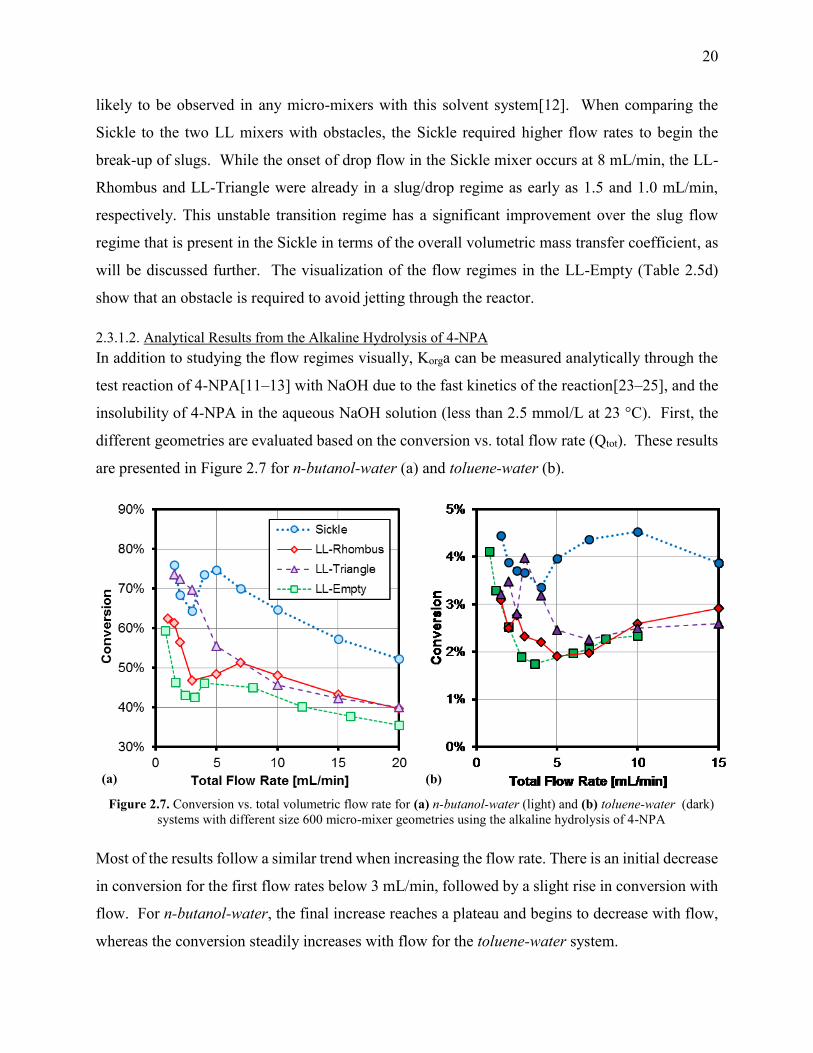
2.3.1.2. Analytical Results from the Alkaline Hydrolysis of 4-NPA
In addition to studying the flow regimes visually, Korga can be measured analytically through the
test reaction of 4-NPA[11–13] with NaOH due to the fast kinetics of the reaction[23–25], and the
insolubility of 4-NPA in the aqueous NaOH solution (less than 2.5 mmol/L at 23 °C). First, the
different geometries are evaluated based on the conversion vs. total flow rate (Qtot). These results
are presented in Figure 2.7 for n-butanol-water (a) and toluene-water (b).
Figure 2.7. Conversion vs. total volumetric flow rate for (a) n-butanol-water (light) and (b) toluene-water (dark)
systems with different size 600 micro-mixer geometries using the alkaline hydrolysis of 4-NPA
Most of the results follow a similar trend when increasing the flow rate. There is an initial decrease
in conversion for the first flow rates below 3 mL/min, followed by a slight rise in conversion with
flow. For n-butanol-water, the final increase reaches a plateau and begins to decrease with flow,
whereas the conversion steadily increases with flow for the toluene-water system.
(a) (b)

21
When studying these conversion data, note that there are competing factors when increasing the
flow rate while in a given flow regime. Residence time decreases with flow, but the mass transfer
rate increases with more energy being dissipated into the system through pressure loss. In a given
flow regime, such as slug or parallel flow, the reduction in residence time is generally a greater
factor, as indicated by the negative slopes in these regions. However, transitions between flow
regimes can lead to a significant variation in interphase mass transfer rate, therefore causing a
pronounced change in conversion. This occurs in the transition to drop flow, where the specific
area available for mass transfer increases substantially. For the toluene-water system in the drop
flow regime, increasing flow can actually have an increase in conversion due to the reduction in
droplet size outcompeting the reduction in residence time for flow rates above 5 mL/min.
In the toluene-water system, the LL-Triangle and LL-Rhombus perform similarly, with the
exception of the slug/drop flow regime; which will be discussed further when directly comparing
the two LL obstacles in section 2.2. For both solvent systems, the obstacles in the LL-Triangle
and LL-Rhombus increased the conversion when compared with the LL-Empty as expected, since
jetting was visible in Table 2.5d. This would create stagnant zones; reducing the surface area
available for mass transfer.
It is important to recognize that the reacting volume in the Sickle plate is roughly double that of
the three LL plates, causing the conversion for the Sickle to be significantly greater. However, the
LL-Triangle results are particularly interesting, as the flow visualizations show that it achieves
drop flow in n-butanol-water at the lowest flow rate (as seen in Table 2.4c and Figure 2.5). The
benefit can clearly be seen in Figure 2.7a where the LL-Triangle, with half the residence time, has
conversions in the range of the Sickle at low flows. The LL-Triangle also does not show any
increase in conversion with flow rate because it has already reached the desired drop flow regime.
While the conversion vs. flow data is interesting in interpreting the flow regime results, it is more
useful to look at the Korga vs. ε since these terms normalize for reactor volume and pressure loss
across the length of the reactor, allowing for the direct comparison between different micro-mixers.
The measured conversion can be related to the overall volumetric mass transfer coefficient with
equation (2.1) by assuming: interphase mass transfer rate is fully rate-limiting; the two phases are
both considered in plug flow; no-slip velocity of the phases.

22
𝐾𝑜𝑟𝑔𝑎 = −
𝜑𝑜𝑟𝑔
𝜏ln (1 − 𝜂)
(2.1)
The average rate of energy dissipation is defined in equation (2.2) and represents the total flow
rate normalized by the reactor volume and total pressure drop. It is based on the density of the
continuous phase, which is the aqueous phase due to the wetted material being stainless steel or
Hastelloy C22™.
휀 =
∆𝑃𝑄𝑡𝑜𝑡
𝜌𝑐𝑉𝑅=
∆𝑃𝜌𝑐𝜏
(2.2)
Comparing Korga vs. ε allows for the analysis of different reactor geometries, regardless of total
reactor volume or number of mixers, and highlights the most efficient geometry for generating a
fine dispersion while using the least energy. The results for all four geometries with n-butanol-
water and toluene-water can be seen in Figure 2.8.
Figure 2.8. Overall volumetric mass transfer coefficient vs. the average rate of energy dissipation for (a) n-butanol-water
(light) and (b) toluene-water (dark) systems with different size 600 micro-mixer geometries using the alkaline hydrolysis of 4-
NPA
It is clear that both of the LL mixers with obstacles achieve higher Korga than the Sickle and LL-
Empty mixers at low flow rates. In addition, the LL-Triangle benefits significantly in the n-
butanol-water system due to the onset of the drop flow regime at low energy dissipations. In the
toluene-water system, the slug/drop flow regime shows the only difference between the LL-
(a) (b)
23
Triangle and LL-Rhombus. Both mixers outperform the Sickle and LL-Empty in the low flow
ranges and, once all mixers have reached drop flow, the Korga vs. ε converge, as expected[11].
While the LL-Empty results seem to be an exception for the convergence of Korga vs. ε in drop
flow, a possible explanation for the results to be consistently lower than the other plates could be
due to dead zones from bypassing. This reactor volume is included in the calculation of Korga and
ε, but no significant reaction is occurring. This further shows that the obstacles in the LL plates
allow the geometry to better utilize the reacting volume.
It is interesting to note that the results in the slug/drop flow regime are not consistent between
repeated runs with the toluene-water. Figure 2.9 shows four repeated runs with the LL-Rhombus
and two with the LL-Triangle. It can be seen that the point at which the flow regime transitions
from slug to drop flow is not a set energy dissipation, but a range between 2 and 10 W/kg. This
can be considered analogous to the single-phase transition from laminar to turbulent flow where,
at a given Reynolds number between 2300 and 4000, either laminar or turbulent flow is
observed[26]. The actual flow regime is subject to environmental factors such as the uniformity
of the fluid’s velocity or the wall roughness. It is possible that in a two-phase system during the
transition from slug to drop flow, the system was particularly sensitive to uncontrollable factors
such as syringe changeover in the pumps (causing slight interruptions in flow every 5-30 seconds).

24
Figure 2.9. Six repeated experiments for the overall volumetric mass transfer coefficient vs. the average rate of
energy dissipation for toluene-water with the size 600 LL-Rhombus and LL-Triangle using the alkaline
hydrolysis of 4-NPA
While stochastic variations from experiment to experiment were observed, the specific flow
regime for a given test is established once the flow rates from the pump achieve steady-state (i.e.
no lag-time at start-up). For this reason, multiple samples were not performed at a given flow rate,
but instead averaged over three to ten residence times. The “development” of the flow regimes, if
any, occurs in the first one to five mixing units (one for highest flow rates, five for lower flow
rates as seen in V.3. in the supporting information).
2.3.2. Further Comparison of LL Mixers
2.3.2.1. Visualization of Flow Regimes for the Toluene-water with SDBS System
The comparison of the LL-Triangle and LL-Rhombus was continued because of their strong
performance relative to the Sickle. To accomplish this, tests were performed with a toluene-water
system with the addition of the surfactant SDBS. Since droplets were formed for all flow rates in
the n-butanol-water system, but not toluene-water, it is important to know the flow regimes for
systems with interfacial tensions between those solvent-pairs. The toluene-water with SDBS was
investigated to determine if the slug/drop flow regime could be avoided to allow for an earlier
onset of drop flow. Table 2.6 and Figure 2.10 show the observed flow regimes and flow regime
map, respectively, for the LL-Rhombus and LL-Triangle reactors. Indeed, the addition of

25
surfactant significantly reduces the flow rate required for the onset of drop flow, with no tested
flow rates exhibiting slug flow.
Table 2.6. Flow regimes at various flow ranges (using interval notation) for the size 600 LL-Rhombus (a) and LL-Triangle (b)
with toluene-water with SDBS surfactant
Flow Regime (a) LL-Rhombus
Visualization [Flow Rate (mL
min)]
Drop
[1.0 – 3.0]
Dispersed
(3.0 – 15.0]
Flow Regime (b) LL-Triangle
Visualization [Flow Rate (mL
min)]
Drop
[1.0 – 2.0]
Dispersed
(2.0 – 15.0]
Figure 2.10. Flow regimes vs. flow rate for the size 600 LL-Rhombus and LL-Triangle in a toluene-water with
SDBS system
2.3.2.2. Analytical Results from the Alkaline Hydrolysis of 4-NPA with the Toluene-water with SDBS
System
The toluene-water with SDBS results for conversion vs. volumetric flow rate are presented in
Figure 2.11. These analytical results follow expected trends since Table 2.6 shows that the flow
regimes in both LL mixers were drop or dispersed for all flow rates tested. Since both plates have
the same total volume and are in the same flow regimes for both solvent systems, it follows that
the conversions should be similar as well.

26
Figure 2.11. Conversion vs. total volumetric flow rate for toluene-water with SDBS systems for the size 600 LL-
Rhombus (LLR, light, solid line) and the LL-Triangle (LLT, dark, dashed line) using the alkaline hydrolysis of 4-
NPA
It is worth considering all three solvent systems together for the LL-Rhombus and LL-Triangle for
the Korga vs. ε. Figure 2.12 shows evidently that the two mixer geometries perform similarly in
the drop flow regime, but the LL-Triangle can reach that flow regime at lower flow rates/energy
dissipations. The reason for this is most likely due to the flow’s impingement against the base of
the triangle obstacle, whereas the LL-Rhombus’ obstacle uses a slicing mechanism of mixing.
Looking at the visualizations for the lowest flows in Table 2.5 (b) and (c), it can be seen that the
LL-Rhombus allows slugs to pass a single side of the obstacle while the LL-Triangle forces the
slug to be split around it. Note that if the obstacle forced a complete change in flow direction (e.g.
a curved obstacle), this could potentially cause parallel flow due to differences in solvent
densities[11].
27
Figure 2.12. Overall volumetric mass transfer coefficient vs. the average rate of energy dissipation with various
solvents for the size 600 LL-Rhombus (light, solid line) and the LL-Triangle (dark, dashed line) using the alkaline
hydrolysis of 4-NPA
While it is interesting that the analytical results of Korga for the toluene-water with SDBS system
eventually converge with the system without surfactant, it is not possible to say that the droplet
sizes would be equal at the highest energy dissipation. There are several factors affecting the rate
of interphase mass transfer when surfactant is present. For example, the surfactant can reduce the
droplet size; however, this can be counteracted by a reduction in the mass transfer coefficient
across the film (Korg) due to the known surface-immobilization of the interface in liquid-liquid[27]
and gas-liquid[28–30] systems. The key finding from testing with the surfactant was the ability to
eliminate the unstable slug/drop flow regime observed in the toluene-water system and obtain
consistent and repeatable mass transfer coefficients.
28
2.3.3. Scale-up of LL Plates
2.3.3.1. Visualization of Flow Regimes
Previous work[13] studied the scale-up of the LL-Rhombus using the “3/7th” scaling rule to
maintain constant rates of energy dissipation at flow rates roughly 10 times those in the size 600.
This led to mixers designed with a hydraulic diameter of 714 μm in the size 300 mixers. Plouffe
et al. showed that the scale-up of the LL-Rhombus achieved similar overall volumetric mass
transfer coefficients for constant energy dissipations at both scales when in the drop flow regime.
This was because the continuous phase is likely turbulent in the drop flow regime where chaotic
eddies dissipate their energy partly via the creation of interfacial area, which leads to smaller drop
sizes that are no longer function of the channel diameter such as for slugs. In order to confirm the
application of the scale-up rule, a size 300 LL-Triangle plate was manufactured and tested with n-
butanol-water and toluene-water systems for flow rates from 10 to 150 mL/min. Figure 2.13
shows the flow regime map for the various solvents; directly comparing the LL-Rhombus and LL-
Triangle for the scaled-up mixers. The observed flow regimes follow a similar trend to what was
seen in the size 600 mixers (with 𝑄300 ≅ 10 ×𝑄600). Again, the LL-Triangle achieved the drop
flow regime at the lowest flow rate studied in n-butanol-water, while the flow regimes were quite
similar between the two mixers for the toluene-water system.
Figure 2.13. Flow regimes vs. flow rate for the size 300 LL-Rhombus and LL-Triangle in n-butanol-water, and
toluene-water systems (lowest flow rate was 10 mL/min)
2.3.3.2. Analytical Results from the Alkaline Hydrolysis of 4-NPA
While the analytical results for the scale-up of the LL-Rhombus are presented in previous
work[13], it is important to confirm the results for the novel LL-Triangle. Figure 2.14 shows the
Korga vs. ε for both sizes 600 and 300 in n-butanol-water and toluene-water systems; the two
systems with the widest range of interfacial tensions. While there are some differences between
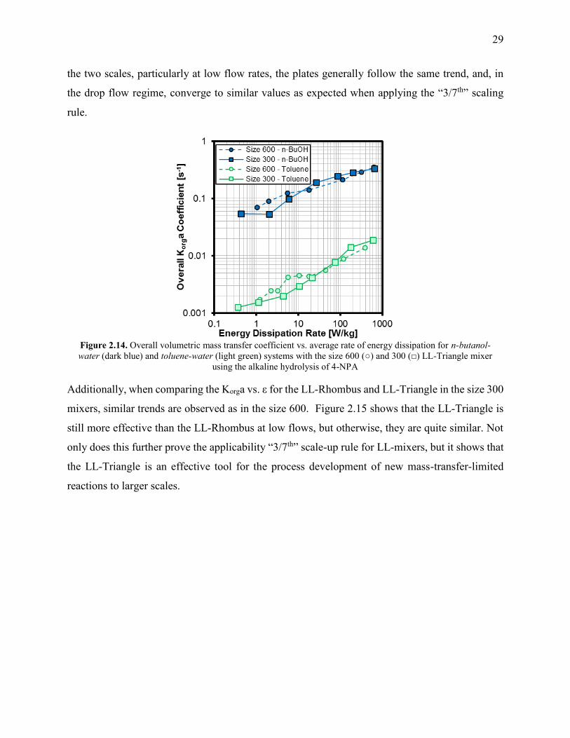
29
the two scales, particularly at low flow rates, the plates generally follow the same trend, and, in
the drop flow regime, converge to similar values as expected when applying the “3/7th” scaling
rule.
Figure 2.14. Overall volumetric mass transfer coefficient vs. average rate of energy dissipation for n-butanol-
water (dark blue) and toluene-water (light green) systems with the size 600 (○) and 300 (□) LL-Triangle mixer
using the alkaline hydrolysis of 4-NPA
Additionally, when comparing the Korga vs. ε for the LL-Rhombus and LL-Triangle in the size 300
mixers, similar trends are observed as in the size 600. Figure 2.15 shows that the LL-Triangle is
still more effective than the LL-Rhombus at low flows, but otherwise, they are quite similar. Not
only does this further prove the applicability “3/7th” scale-up rule for LL-mixers, but it shows that
the LL-Triangle is an effective tool for the process development of new mass-transfer-limited
reactions to larger scales.

30
Figure 2.15. Overall volumetric mass transfer coefficient vs. the average rate of energy dissipation for n-butanol-
water (light) and (b) toluene-water (dark) systems with the size 300 LL-Rhombus and LL-Triangle using the
alkaline hydrolysis of 4-NPA
It is important to note that size 300 mixers are intended to be used on a larger micro-reactor system
than the FlowPlate® Lab (size A7) and they were manufactured primarily for flow-visualization
purposes. The scaled-up reactor plates can only fit 21 mixing units whereas, for example, the
FlowPlate A6 system could fit 113 mixers. There is presumably a minimum number of mixers
required to reach a given fully developed flow regime and this entrance region in the size 300 A7
plate is likely significant when comparing with results from size 600 plates.
Additionally, the FlowPlate Lab (size A7) system inlet and outlet ports are on the same order of
magnitude in hydraulic diameter as the size 300 mixers, and with the higher flows being studied,
it is no longer applicable to assume that the energy dissipation, and therefore the mixing, in the
outlet is negligible.
2.4. Conclusions
Several obstacle-based micro-mixer geometries were studied with up to four different solvent-pair
systems for two different mixer sizes. The liquid-liquid systems were observed and classified
based on some combination of the following flow regimes: slug flow; parallel flow; or drop flow.
For applications in fast liquid-liquid reactions, drop flow is the ideal flow regime due to the
increased specific area available for interphase mass transfer. The alkaline hydrolysis of 4-
nitrophenyl acetate was used as a test reaction to measure analytically the overall volumetric mass
31
transfer coefficients in the various mixers. The micro-mixers were evaluated based on the Korga
plotted vs. the average rate of energy dissipation to determine the most efficient mixer design (i.e.,
the mixer with the earliest onset of drop flow).
In the flow range of 1-20 mL/min, the novel LL-Triangle micro-mixer design was shown to
perform equally well as or better than any of the other micro-mixers studied in all solvent-pairs
investigated, namely the Sickle, the LL-Rhombus, and the LL-Empty. The benefits for this mixer
were most clearly observed at low flow rates for low interfacial tension systems, such as n-butanol-
water, where the drop flow regime was observed at the lowest energy dissipation. In the toluene-
water system, both LL-mixers performed similarly, with a slug/drop flow regime observed for low
flows. It was possible to avoid this transition regime with the use of a surfactant in the toluene-
water system. Drop flow was observed in both LL-mixers at lower energy dissipations than the
Sickle mixer and unwanted parallel flow was avoided due to the reduced curvature.
The results were reproduced in a larger scale LL-Triangle for flow rates between 10-150 mL/min
where the LL-Triangle achieved drop flow again for all flow rates studied in n-butanol-water. The
overall volumetric mass transfer coefficients were similar to those obtained at equal energy
dissipations in the smaller scale in the drop flow regime; indicating that the LL-Triangle micro-
mixer is excellent for the process development and scale-up of fast liquid-liquid reactions. Finally,
for liquid-liquid reactive systems, this work nicely shows that a flow visualization is of prime
importance to enable determination of the proper flow regime and ensure consistent scale-up.
2.5. Nomenclature
Symbol Description (units)
General
a specific interfacial area of contact (m2/m3)
b width of the channel at contraction (m)
dh hydraulic diameter at contraction = 𝟐𝒉𝒃/(𝒉 + 𝒃) (m)
h depth of the channel at contraction (m)
K overall convective mass transfer coefficient (m/s)
Q volumetric flow rate (m3/s)
V Volume (m3)
ΔP Pressure drop across the reactor (Pa)
Greek Symbols
휀 average rate of energy dissipation (W/kg)
𝜂 conversion (%)
32
𝜇 fluid viscosity (Pa·s)
𝜌 fluid density (kg/m3)
𝜎 fluid interfacial tension with water (N/m)
𝜏 average residence time (s)
𝜑 volumetric phase fraction
Subscripts
aq aqueous phase
c continuous phase
d dispersed phase
org organic phase
tot total (sum of organic and aqueous phase)
R reactor
300 in a size 300 micro-mixer; dh = 714 μm
600 in a size 600 micro-mixer; dh = 286 μm
Acknowledgements. The authors would like to thank the Natural Sciences and Engineering
Research Council of Canada, including the CREATE program in Continuous Flow Science, and
Lonza AG for their financial contribution. Also, Ehrfeld Mikrotechnik BTS is acknowledged for
the reactor manufacturing.
Supporting Information Available: Supplementary videos of various flow regimes (V.1., LL-
Triangle — n-Butanol-water.mp4; V.2., LL-Triangle —Toluene-water.mp4; V.3., LL-Triangle
Size 300 — n-Butanolwater.mp4) associated with this article can be found in the
online version at doi: 10.1556/1846.2016.00026.
2.6. References
[1] V. Kumar, M. Paraschivoiu, K.D.P. Nigam, Single-phase fluid flow and mixing in
microchannels, Chem. Eng. Sci. 66 (2011) 1329–1373. doi:10.1016/j.ces.2010.08.016.
[2] C.P. Holvey, D.M. Roberge, M. Gottsponer, N. Kockmann, A. Macchi, Pressure drop and
mixing in single phase microreactors: Simplified designs of micromixers, Chem. Eng.
Process. Process Intensif. 50 (2011) 1069–1075. doi:10.1016/j.cep.2011.05.016.
[3] P. Plouffe, R. Anthony, A. Donaldson, D.M. Roberge, N. Kockmann, A. Macchi,
Transport Phenomena in Two-Phase Liquid-Liquid Micro-Reactors, in: ASME 2012 10th
Int. Conf. Nanochannels, Microchannels, Minichannels, Rio Grande, Puerto Rico, 2012.
http://proceedings.asmedigitalcollection.asme.org/proceeding.aspx?articleid=1719073
(accessed August 19, 2014).
[4] N. Kockmann, M. Gottsponer, D.M. Roberge, Scale-up concept of single-channel
microreactors from process development to industrial production, Chem. Eng. J. 167
(2011) 718–726. doi:10.1016/j.cej.2010.08.089.

33
[5] M. Kashid, A. Renken, L. Kiwi-Minsker, Mixing efficiency and energy consumption for
five generic microchannel designs, Chem. Eng. J. 167 (2011) 436–443.
doi:10.1016/j.cej.2010.09.078.
[6] L. Falk, J.M. Commenge, Performance comparison of micromixers, Chem. Eng. Sci. 65
(2010) 405–411. doi:10.1016/j.ces.2009.05.045.
[7] V. Hessel, D. Kralisch, N. Kockmann, T. Noel, Q. Wang, Novel Process Windows for
Enabling, Accelerating, and Uplifting Flow Chemistry, ChemSusChem. 6 (2013) 746–
789. doi:10.1002/cssc.201200766.
[8] L. Ducry, D.M. Roberge, Controlled Autocatalytic Nitration of Phenol in a Microreactor,
Angew. Chemie - Int. Ed. 44 (2005) 7972–7975. doi:10.1002/anie.200502387.
[9] M.N. Kashid, L. Kiwi-Minsker, Microstructured Reactors for Multiphase Reactions: State
of the art, Ind. Eng. Chem. Res. 48 (2009) 6465–6485. doi:10.1021/ie8017912.
[10] G. Dummann, U. Quittmann, L. Gröschel, D.W. Agar, O. Wörz, K. Morgenschweis, The
Capillary-Microreactor: A New Reactor Concept for the Intensification of Heat and Mass
Transfer in Liquid-Liquid Reactions, Catal. Today. 79–80 (2003) 433–439.
doi:10.1016/S0920-5861(03)00056-7.
[11] P. Plouffe, D.M. Roberge, A. Macchi, Liquid–liquid flow regimes and mass transfer in
various micro-reactors, Chem. Eng. J. 300 (2016) 9–19. doi:10.1016/j.cej.2016.04.072.
[12] P. Plouffe, D.M. Roberge, J. Sieber, M. Bittel, A. Macchi, Liquid–liquid mass transfer in
a serpentine micro-reactor using various solvents, Chem. Eng. J. 285 (2016) 605–615.
doi:10.1016/j.cej.2015.09.115.
[13] P. Plouffe, M. Bittel, J. Sieber, D.M. Roberge, A. Macchi, On the scale-up of micro-
reactors for liquid–liquid reactions, Chem. Eng. Sci. 143 (2016) 216–225.
doi:10.1016/j.ces.2015.12.009.
[14] P. Plouffe, A. Macchi, D.M. Roberge, From batch to continuous chemical synthesis-a
toolbox approach, Org. Process Res. Dev. 18 (2014) 1286–1294. doi:10.1021/op5001918.
[15] M.J. Nieves-Remacha, A. a. Kulkarni, K.F. Jensen, Gas–Liquid Flow and Mass Transfer
in an Advanced-Flow Reactor, Ind. Eng. Chem. Res. 52 (2013) 8996–9010.
http://dx.doi.org/10.1021/ie4011707.
[16] E.D. Lavric, P. Woehl, Advanced-Flow TM glass reactors for seamless scale-up, Chem.
Today. 27 (2009) 45–48.
[17] M. N. Kashid, A. Renken, L. Kiwi-Minsker, Influence of Flow Regime on Mass Transfer
in Different Types of Microchannels, Ind. Eng. Chem. Res. 50 (2011) 6906–6914.
doi:10.1021/ie102200j.
[18] M.J. Nieves-Remacha, A.A. Kulkarni, K.F. Jensen, Hydrodynamics of Liquid–Liquid
Dispersion in an Advanced-Flow Reactor, Ind. Eng. Chem. Res. 51 (2012) 16251–16262.
doi:10.1021/ie301821k.

34
[19] H.M. Backes, J.J. Ma, E. Bender, G. Maurer, Interfacial tensions in binary and ternary
liquid—liquid systems, Chem. Eng. Sci. 45 (1990) 275–286. doi:10.1016/0009-
2509(90)87099-E.
[20] A. Berthod, N. Schmitt, Water—organic solvent systems in countercurrent
chromatography: Liquid stationary phase retention and solvent polarity, Talanta. 40
(1993) 1489–1498. doi:10.1016/0039-9140(93)80358-X.
[21] D.J. Donahue, F.E. Bartell, The Boundary Tension at Water-Organic Liquid Interfaces, J.
Phys. Chem. 56 (1952) 480–484. doi:10.1021/j150496a016.
[22] A.A. Alexandrov, The Equations for Thermophysical Properties of Aqueous Solutions of
Sodium Hydroxide, 14th Int. Conf. Prop. Water Steam. (2005) 86–90.
http://www.iapws.jp/Proceedings/Symposium02/086Alexandrov.pdf.
[23] B. Ahmed-Omer, D. Barrow, T. Wirth, Effect of segmented fluid flow, sonication and
phase transfer catalysis on biphasic reactions in capillary microreactors, Chem. Eng. J.
135 (2008) S280–S283. doi:10.1016/j.cej.2007.07.017.
[24] B. Ahmed, D. Barrow, T. Wirth, Enhancement of reaction rates by segmented fluid flow
in capillary scale reactors, Adv. Synth. Catal. 348 (2006) 1043–1048.
doi:10.1002/adsc.200505480.
[25] V.D. Parker, Instantaneous rate constants in physical organic chemistry: Application to
acyl transfer reactions of p-nitrophenyl acetate to hydroxide ion, J. Phys. Org. Chem. 19
(2006) 714–724. doi:10.1002/poc.1064.
[26] M.C. Potter, D.C. Wiggert, B.H. Ramadan, Mechanics of Fluids, 4th ed., Cengage
Learning, Stamford, CT, 2011.
[27] R. Clift, J.R. Grace, M.E. Weber, Bubbles, drops, and particles, Dover Publications, Inc.,
Mineola, New York, 1978.
[28] K. Koide, S. Yamazoe, S. Harada, Effects of Surface-Active Substances on Gas Holdup
and Gas-Liquid Mass Transfer in Bubble Column., J. Chem. Eng. Japan. 18 (1985) 287–
292.
[29] J.J. Jeng, J.R. Maa, Y.M. Yang, Surface effects and mass transfer in bubble column, Ind.
Eng. Chem. Process Des. Dev. 25 (1986) 974–978. doi:10.1021/i200035a023.
[30] W.W. Eckenfelder, E.L. Barnhart, The effect of organic substances on the transfer of
oxygen from air bubbles in water, AIChE J. 7 (1961) 631–634.
doi:10.1002/aic.690070420.
35
3. Investigation of Overall and Localized Heat Transfer in Curved Micro-
Channel Reactor Systems
Eric Mielke,a Patrick Plouffe,a Nikhil Koushik,a Markus Eyholzer,b Michael Gottsponer,b Norbert
Kockmann,c Arturo Macchia,* and Dominique M. Roberge,b,*
a, Centre for Catalysis Research and Innovation, Department of Chemical and Biological Engineering, University
of Ottawa, K1N 6N5 Ottawa, Canada.
b, Chemical Manufacturing Technologies, Lonza AG, CH-3930 Visp, Switzerland.
c, University of Technology Dortmund, Biochemical and Chemical Engineering, Equipment Design, Emil-Figge-Str.
68, D-44227 Dortmund, Germany
This manuscript will be submitted for publication in 2017
ABSTRACT
Non-reactive and reactive heat transfer experiments were performed in the FlowPlate® system by
Ehrfeld Mikrotechnik BTS, which is composed of alternating reactor and heat transfer fluid plates
within a rack. The non-reactive system studied a rectangular serpentine channel with Reynolds
numbers ranging from 400-2000, and a Gnielinski-type model was fit to the internal Nusselt
number. A silver-based thermal paste was shown to reduce the external resistance to heat transfer
between the reactor and heat transfer fluid plates by ~70%, leading to overall heat transfer
coefficients of ~2200 [𝑊 (𝑚2 𝐾)⁄ ]. In the reactive system, the synthesis of methyl 2-
oxobutanoate, using dimethyl-oxalate and the Grignard reagent ethylmagnesium chloride, was
highlighted as a test reaction to differentiate localized heat transfer characteristics across different
reactors. The Grignard reaction was used to compare the impact of various micro-mixer
geometries, materials, injection ports, and scales on hotspot formation in the reactors. Finally, an
analysis of four case studies was presented using the fourth Damköhler number to determine a
maximum channel diameter that would remove sufficient heat to avoid hotspot formation, based
on experimentally determined overall heat transfer coefficients.
Keywords: Micro-reactor, overall heat transfer, localized heat transfer, transitional flow,
serpentine channels

36
3.1. Introduction
The field of continuous-flow micro-reactor technology has been gaining academic and industrial
interest in recent years due to its many advantages over batch processes at smaller scales [1–4].
Micro-reactors potentially offer enhanced transport rates including wall-to-fluid heat transfer due
to relatively small channel dimensions and high surface-area-to-volume ratios when compared to
batch or larger-scale continuous flow reactors [1–7]. Notwithstanding the fact that a single micro-
reactor is not a general solution to all type of reactions [8], Plouffe et al. developed a toolbox
approach where the preferred reactor system is chosen for the given reaction rate, reaction network,
and phase type [9]. This toolbox encompasses the use of micro-structure plates where beneficial,
namely during the intense mixing/heat exchange portion of a reaction, while more conventional
modules like a coil or tubular heat exchangers are used afterward for an effective increase in
volume.
In relation to heat exchange, three cases can be considered which are a function of the reaction rate
(Type A, B, and C). For Type A reactions (millisecond to second), even with micro-structures, a
hot spot can be formed and, in general, it is controlled via the multi-injection principle [10].
Organo-Grignard reactions are an example of intensely exothermic type A systems with a complex
network of reactions that occur in the hot spot [11]. The Grignard reaction reported by Plouffe et
al. [9], which shows a very high resolution in side-product formation as a function of the hot spot
magnitude, makes it well suited to understand localized heat effects. It will be used here to further
study different micro-reactor systems. Type B reactions have intermediate kinetics (between
several seconds and minutes), but may still be fast enough to require significant heat exchange to
reduce spatial variations in thermal conditions. A multi-scale approach is appropriate where the
hydraulic diameter of a reactor is adjusted via a different plate or coil diameter depending on the
local reaction kinetics (vide infra). Type C reactions have slower kinetics (between several minutes
to hours) and can often be handled by conventional technology [9], except for cases with
particularly hazardous chemicals or operating conditions.
The scale-up of production using micro-structures is often limited by the pressure drop, and a plate
type reactor is generally more straightforward to scale up than a coil reactor. Figure 3.1 shows a
Mix-Then-Reside (MTR) plate, where the initial mixing zone (in this case SZ) is the main
contributor to the pressure drop of the plate. The hydraulic diameter of this mixing zone can be

37
adjusted for various flow rates via the 3/7th power rule as explained in [12]. On the other hand,
upon scale-up, the residence time channel (RTC) may be enlarged in width (𝑤) while the depth
(𝑑) is kept constant to maintain similar hydrodynamic conditions (and similar ℎ𝑖𝑛) and hydraulic
diameter leading also to a similar specific surface area for heat exchange (𝑎). In fact, when such
an approach is integrated into various sized-plates (A7, A6, A5…; Table 3.1, Figure 3.2), pressure
drop can be kept reasonable for a single plate leading to high flow rates and productivity.
Combined with a multi-scale approach, even longer residence times can be accommodated with
the proper reactor unit while maintaining relatively low pressure losses. In other words, the size
increase of a plate is consistent with the increase of volume (𝑉) and surface area leading to a
consistent scale-up, as opposed to the increase of the diameter of a coil; where 𝑎 is inversely
proportional to 𝑉.
Figure 3.1. FlowPlate® Lab SZ Mix-Then-Reside (MTR) reactor plates manufactured by Ehrfeld
Mikrotechnik BTS size 600 (left) and 300 (right)
Table 3.1. FlowPlate® sizes and production capacities
Plate Size
Flow Rate
[mL/min] Quantity*
FlowPlate® Lab
(close to A7) 1.5-15
Development tool,
few grams
FlowPlate® A6 15-150
6,500-65,000 kg
FlowPlate® A5 150-300
65,000-130,000 kg
FlowPlate® A4 300-600
130,000-260,000 kg
*Isolated product per year with product concentration from 10-100
wt% and density ~1000 kg/m3
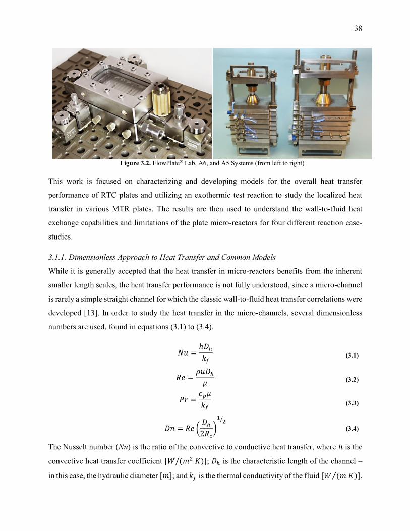
38
Figure 3.2. FlowPlate® Lab, A6, and A5 Systems (from left to right)
This work is focused on characterizing and developing models for the overall heat transfer
performance of RTC plates and utilizing an exothermic test reaction to study the localized heat
transfer in various MTR plates. The results are then used to understand the wall-to-fluid heat
exchange capabilities and limitations of the plate micro-reactors for four different reaction case-
studies.
3.1.1. Dimensionless Approach to Heat Transfer and Common Models
While it is generally accepted that the heat transfer in micro-reactors benefits from the inherent
smaller length scales, the heat transfer performance is not fully understood, since a micro-channel
is rarely a simple straight channel for which the classic wall-to-fluid heat transfer correlations were
developed [13]. In order to study the heat transfer in the micro-channels, several dimensionless
numbers are used, found in equations (3.1) to (3.4).
𝑁𝑢 =ℎ𝐷ℎ
𝑘𝑓 (3.1)
𝑅𝑒 =𝜌𝑢𝐷ℎ
𝜇 (3.2)
𝑃𝑟 =𝑐𝑝𝜇
𝑘𝑓 (3.3)
𝐷𝑛 = 𝑅𝑒 (𝐷ℎ
2𝑅𝑐)
12⁄
(3.4)
The Nusselt number (Nu) is the ratio of the convective to conductive heat transfer, where ℎ is the
convective heat transfer coefficient [𝑊/(𝑚2 𝐾)]; 𝐷ℎ is the characteristic length of the channel –
in this case, the hydraulic diameter [𝑚]; and 𝑘𝑓 is the thermal conductivity of the fluid [𝑊 (𝑚 𝐾)⁄ ].

39
The Reynolds number (Re) is the ratio of the fluid’s inertial and viscous forces, where 𝜌 is the
fluid density [𝑘𝑔/𝑚3]; 𝑢 is the fluid velocity [𝑚/𝑠]; and 𝜇 is the fluid’s viscosity [𝑃𝑎 𝑠]. The
Prandtl number (Pr) is the ratio of the rates of viscous diffusion and thermal diffusion, where 𝑐𝑝
is the fluid’s heat capacity [𝐽/(𝑘𝑔 𝐾)]. Lastly, the Dean number (Dn) is used to characterize flow
in curved ducts, where 𝑅𝑐 is the radius of curvature [𝑚].
For heat transfer studies in micro-reactors and micro-channels, there is little agreement in the
literature on whether conventional, macro-scale correlations apply to the smaller scale systems
[7,13–15]. Morini [14], as well as Steinke and Kandlikar [15], performed literature reviews on the
available heat transfer data and found little consistency, concluding that further work is required
in the field. Morini observed that when analyzing all data chronologically, the overall deviations
between studies were decreasing. This trend was attributed to the technological improvements in
the construction of the micro-channels, reducing the relative roughness and uncertainties in
channel dimensions. Steinke and Kandlikar considered three key, underlying causes specific to
research in micro-reactor systems responsible for the differences in various investigations [7,15]:
the thermal entrance regions in relatively short micro-reactors; uncertainties in experimental
measurements (e.g. small channel dimensions, wall temperatures, etc.); and ambiguity in the
determination of the thermal boundary condition. These factors were taken into account when
developing the experimental protocols used in this work.
For macro-scale systems in the fully developed laminar flow regime (Re<2,300), the Nusselt
number is typically constant for straight channels [16]; while in the transitional
(2,300<Re<10,000) and turbulent (Re>10,000) flow regimes, Nu can be described in terms of Re
and Pr. Many studies claim that there is an early transition to turbulence in micro-channels;
however, Steinke and Kandlikar showed that these studied did not account for developing flow or
uncertainty in their calculations [15]. Nevertheless, due to the curvature of the micro-channels
studied here, vortices can form, and secondary flow patterns can become chaotic at Reynolds
numbers below typical transitional flow conditions [17–21], even when high aspect ratios (𝛼) are
employed [22]. These chaotic flow patterns are suspected to influence the Nusselt number in
similar ways to turbulent flow, rather than Nu remaining constant, as in laminar flow. For this
reason, several empirical Nusselt number correlations that are valid for transitional and turbulent
flow regimes (Re>2300), regardless of boundary conditions [13], are considered, even though the

40
range of this study is 400<Re<2000. It is worth noting that the channels studied here in this range
of Reynolds numbers can be considered hydraulically smooth, as the relative roughness is
approximately 4×10⁻⁴ [23].
The Dittus-Boelter correlation was the simplest model considered where 𝑁𝑢𝐷𝐵 is a function of
Re0.8. This model is typically sufficient when the fluid properties can be assumed to be constant
across the studied temperature range [13] and was developed for 0.6 ≤ 𝑃𝑟 ≤ 160 and 𝑅𝑒 ≥
10,000. The Sieder-Tate correlation (𝑁𝑢𝑆𝑇, valid for 0.7 ≤ 𝑃𝑟 ≤ 16,700 and 𝑅𝑒 ≥ 10,000)
extends upon this by incorporating a ratio between 𝜇, the viscosity evaluated at the bulk
temperature (𝑇��), and 𝜇𝑠, the viscosity evaluated at the surface temperature, 𝑇𝑠. This model is more
accurate when there are larger temperature gradients in the system, as it accounts for the transport
phenomena at the boundary conditions [13].
Lastly, the Gnielinski correlation (𝑁𝑢𝐺𝑛) was considered because it is an accurate model for
transitional and turbulent regimes since it incorporates a friction factor into its calculation, shown
in equation (3.5). The Darcy–Weisbach friction factor, 𝑓, used in its calculation is given in
equation (3.6), where ∆𝑃 is the pressure loss, in [𝑃𝑎], across the reactor length 𝑙, in [𝑚].
𝑁𝑢𝐺𝑛 =(𝑓 8⁄ )(𝑅𝑒 − 1000)𝑃𝑟
1 + 12.7(𝑓 8⁄ )1 2⁄ (𝑃𝑟2 3⁄ − 1)
[0.5 ≤ 𝑃𝑟 ≤ 2,000
3,000 ≤ 𝑅𝑒 ≤ 5×10⁶]
(3.5)
𝑓 =2 ∆𝑃
𝜌𝑢2 (
𝐷ℎ
𝑙)
(3.6)
The Gnielinski correlation was developed for macro-scale applications, and Adams et al. showed
that the correlation is sufficient in modeling Nu for non-circular channels with 𝐷ℎ as small as 1.2
mm [24]. They also showed that for smaller channel sizes, such as those studied here, a deviation
factor can be applied to the Gnielinski correlation to achieve better predictions for Nu [25].
Although the Gnielinski model (with the deviation factor from Adams) would have been the
preferred model, the term (𝑅𝑒 − 1000) would become negative for the range of flows that were
studied, and this would not yield meaningful results. Therefore, a modified Gnielinski model will

41
be developed as in equation (3.7) where 𝛽 and 𝛾 will be fit using the least squared error, ensuring
that 𝛽 is smaller than smallest Re studied (400).
𝑁𝑢𝐺𝑛 =(𝑓 8⁄ )(𝑅𝑒 − 𝜷)𝑃𝑟
1 + 𝜸(𝑓 8⁄ )1 2⁄ (𝑃𝑟2 3⁄ − 1)
(3.7)
3.2. Experimental and Analytical Methods
3.2.1. Reactors Studied
3.2.1.1. RTC Plate used with a Non-Reactive System
The first investigation utilized an A6-sized FlowPlate® reactor manufactured by Ehrfeld
Mikrotechnik BTS (Figure 3.3); namely the 320B, which is an RTC using half of the plate’s area,
shown in Figure 3.4. This RTC plate was chosen because it has a smaller operating volume with
the same channel dimensions as the standard 321 RTC plate, which uses the entire A6 plate. The
‘B’ side was chosen over the ‘A’ side for ease of setup due to both inlet and outlet facing upwards,
in addition to having more curves relative to the total volume, similar to the RTC sections on
several MTR plates. The detailed dimensions of this plate can be found in Table 3.2. The RTC
plate (in addition to the A5-sized plates used in the reactive system discussed below) was
manufactured out of a 3.5 mm thick Hastelloy® C22 plate with a 1.5 mm plate welded to the other
side; so, the metal’s thickness is dependent on the channel’s depth at that point. The thermal
conductivity of Hastelloy® C22 is 10.9 [𝑊/(𝑚 𝐾)] [26], significantly lower than that of
Aluminium (273 [𝑊/(𝑚 𝐾)] at 300 K) [23] with which the Heat Transfer Fluid (HTF) plates were
made (new HTF plates are manufactured with copper with k=400 𝑊/(𝑚 𝐾)] [23]). The reactor
plates and heat transfer fluid plates alternate in the FlowPlate® system, as shown in Figure 3.3.
The HTF flow is operated in the turbulent regime at Reynolds numbers over 15000 to minimize
the resistance to fluid-to-wall heat transfer in the HTF channel.

42
Figure 3.3. FlowPlate® A6 Reactor system manufactured by Ehrfeld Mikrotechnik BTS (left, back), single
reactor plate (left, front), and an open MTR (SZ) reactor plate revealing the channels (right)
Figure 3.4. CAD drawings of the 320 RTC plate
A B

43
Table 3.2. Reactor plate properties
Parameter 320B 315 215 240 260 350 [Units]
Plate size A6 A6 A5 A5 A5 A5
Plate material Hastelloy® Hastelloy® Hastelloy® Hastelloy® Hastelloy® SiC
Plate Type RTC MTR MTR MTR MTR MTR
Mixing Zone
Mixer Type - SZ SZ TG TG TG
Mixer Size - 300 200 200 100 200*
𝑫𝒉 - 0.714 1.00 1.00 1.375 0.747 [mm]
𝒘 - 0.5 0.7 0.7 1.0 0.7 [mm]
𝒅 - 1.25 1.75 1.75 2.2 0.8* [mm]
𝑨𝑴𝑬 - 4.61 x 10⁻⁵ 8.40 x 10⁻⁵ 8.84 x 10⁻⁵ 1.85 x 10⁻⁴ 6.50 x 10⁻⁵ [m2]
𝑽𝑴𝑬 - 6.74 x 10⁻⁹ 1.7 x 10⁻⁸ 3.96 x 10⁻⁸ 1.02 x 10⁻⁷ 1.81 x 10⁻⁸ [m3]
Specific area - 6840 4890 2230 1820 3590 [m2/m3]
Residence Time Channel
𝑫𝒉 0.901 0.901 0.952 1.38 1.31 1.38 [mm]
𝒘 5.0 5.0 10.0 5.0 10.0 5.0 [mm]
𝒅 0.5 0.5 0.5 0.8 0.7 0.8 [mm]
𝒍 617 - - - - - [mm]
𝑨𝑹 0.00679 - - - - - [m2]
𝑽𝑹 1.54 x 10⁻⁶ - - - - - [m3]
Specific area 4400 - - - - - [m2/m3]
𝑹𝒄 4.5 - - - - - [mm]
*Not truly a size 200 due to reduced channel depth
3.2.1.2. MTR Plates used with a Reactive System
For the reactive system, the five MTR plates from Table 3.2 were used; each with a different mixer
type (SZ or TG, as shown in Figure 3.5), scale (300, 200, or 100) or material (Hastelloy® C22 or
SiC). Since the reaction is fast and occurs within a few milliseconds inside the reactor plate [9], it
is only the geometry of a particular mixing-element that is of interest when comparing the five
different plates. It is important to note that plate 350, the SiC TG plate, was custom built and has
the HTF built into the plate (i.e. there is no contact resistance). The four other MTR plates fit into
the FlowPlate® reactor system (either the size A5 or A6 rack, depending on plate) as with the non-
reactive system described previously.
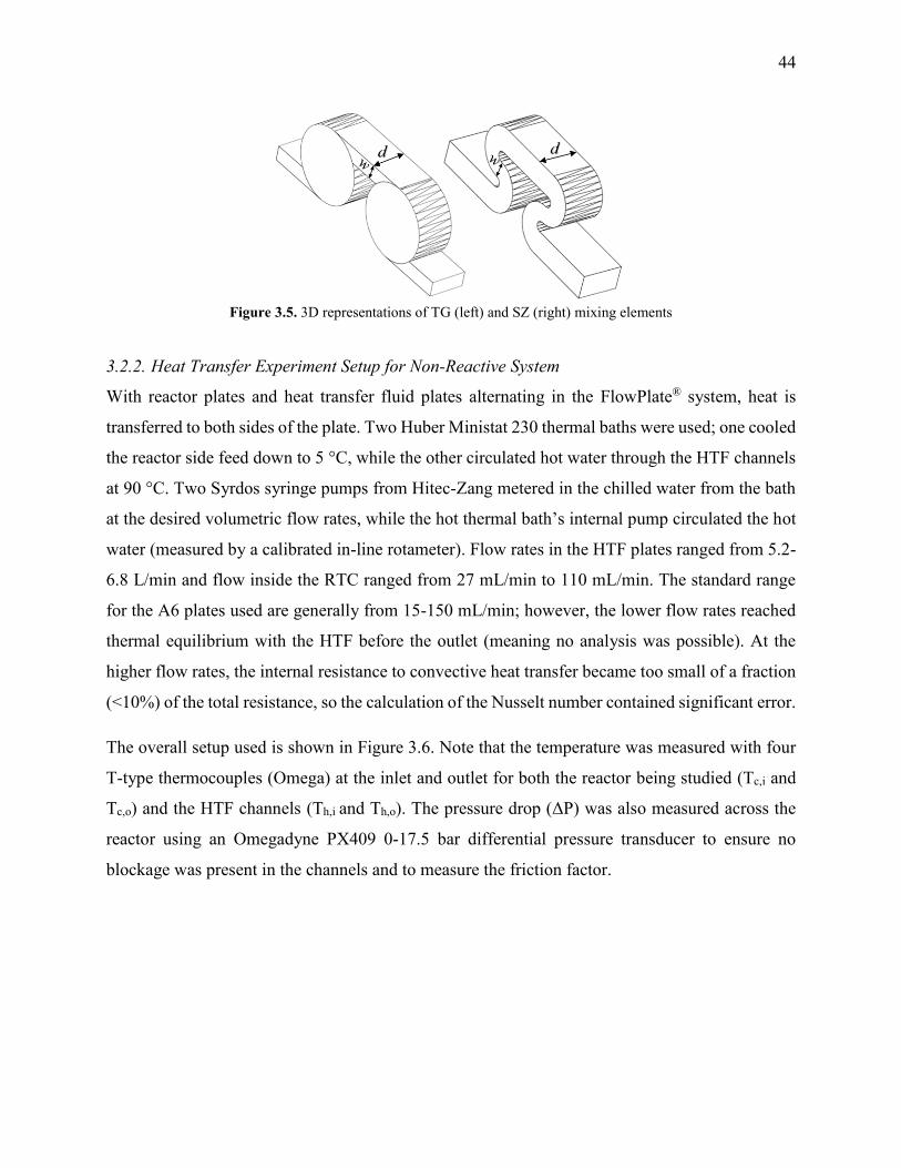
44
Figure 3.5. 3D representations of TG (left) and SZ (right) mixing elements
3.2.2. Heat Transfer Experiment Setup for Non-Reactive System
With reactor plates and heat transfer fluid plates alternating in the FlowPlate® system, heat is
transferred to both sides of the plate. Two Huber Ministat 230 thermal baths were used; one cooled
the reactor side feed down to 5 °C, while the other circulated hot water through the HTF channels
at 90 °C. Two Syrdos syringe pumps from Hitec-Zang metered in the chilled water from the bath
at the desired volumetric flow rates, while the hot thermal bath’s internal pump circulated the hot
water (measured by a calibrated in-line rotameter). Flow rates in the HTF plates ranged from 5.2-
6.8 L/min and flow inside the RTC ranged from 27 mL/min to 110 mL/min. The standard range
for the A6 plates used are generally from 15-150 mL/min; however, the lower flow rates reached
thermal equilibrium with the HTF before the outlet (meaning no analysis was possible). At the
higher flow rates, the internal resistance to convective heat transfer became too small of a fraction
(<10%) of the total resistance, so the calculation of the Nusselt number contained significant error.
The overall setup used is shown in Figure 3.6. Note that the temperature was measured with four
T-type thermocouples (Omega) at the inlet and outlet for both the reactor being studied (Tc,i and
Tc,o) and the HTF channels (Th,i and Th,o). The pressure drop (ΔP) was also measured across the
reactor using an Omegadyne PX409 0-17.5 bar differential pressure transducer to ensure no
blockage was present in the channels and to measure the friction factor.

45
Figure 3.6. Schematic of heat transfer experimental setup
When assembling the FlowPlate® system, the plates were tightened to a torque of 15 [𝑁 𝑚], the
specification given by the manufacturer. This was maintained for all experiments because this
would significantly affect the contact resistance between the plates. A silver-based thermal paste
purchased from McMaster-Carr was used to test the contact resistance. It was chosen due to its
high thermal conductivity of (104 [𝑊/(𝑚 𝐾)]) in order to fill any gaps between the plates [27].
In order to insulate the system from the environment, a Styrofoam box was constructed with the
required ports for the fluids to enter and exit the system, as well as the instrumentation wiring. The
FlowPlate® A6 rack was in the box, surrounded by fiberglass insulation. This was done to ensure
that the experiments were unaffected by the surrounding ambient temperature.
3.2.2.1. Water Properties at Temperatures Studied
The properties of water could not be assumed as constant throughout the reactor since this work
was performed over a relatively wide range of temperatures (5-90 °C). The values for each
property used at various temperatures are shown in Table 3.3 [28]. Note that, unless specified
otherwise (e.g. viscosity at the wall temperature), the properties are evaluated at the average cold-
side or hot-side temperatures, 𝑇�� and 𝑇ℎ , respectively.
FISyringe
Pump #1
Syringe
Pump #2
Thermal
Bath (Cold)
Thermal
Bath (Hot)
Microreactor
PT
Th,o Th,i
Tc,o
PT
Tc,i
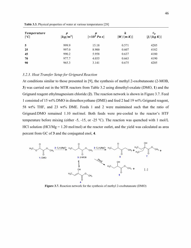
46
Table 3.3. Physical properties of water at various temperatures [28]
𝑻𝒆𝒎𝒑𝒆𝒓𝒂𝒕𝒖𝒓𝒆
[°𝑪] 𝝆
[𝒌𝒈/𝒎𝟑] 𝝁
[×𝟏𝟎𝟒 𝑷𝒂 𝒔] 𝒌
[𝑾 (𝒎 𝑲)⁄ ]
𝒄𝒑
[𝑱 (𝒌𝒈 𝑲)⁄ ]
5 999.9 15.18 0.571 4205
25 997.0 8.900 0.607 4182
45 990.2 5.958 0.637 4180
70 977.7 4.035 0.663 4190
90 965.3 3.141 0.675 4205
3.2.3. Heat Transfer Setup for Grignard Reaction
At conditions similar to those presented in [9], the synthesis of methyl 2-oxobutanoate (2-MOB,
3) was carried out in the MTR reactors from Table 3.2 using dimethyl-oxalate (DMO, 1) and the
Grignard reagent ethylmagnesium chloride (2). The reaction network is shown in Figure 3.7. Feed
1 consisted of 15 wt% DMO in dimethoxyethane (DME) and feed 2 had 19 wt% Grignard reagent,
58 wt% THF, and 23 wt% DME. Feeds 1 and 2 were maintained such that the ratio of
Grignard:DMO remained 1.10 mol/mol. Both feeds were pre-cooled to the reactor’s HTF
temperature before mixing (either -5, -15, or -25 °C). The reaction was quenched with 1 mol/L
HCl solution (HCl/Mg = 1.20 mol/mol) at the reactor outlet, and the yield was calculated as area
percent from GC of 3 and the conjugated enol, 4.
Figure 3.7. Reaction network for the synthesis of methyl 2-oxobutanoate (DMO)

47
3.2.4. Analytical Methods
3.2.4.1. Isolation of Nu from experimental data
In order to determine the Nusselt number for a given channel, an energy balance is performed on
the cold stream (the inner channel). The energy gained by the cold stream (𝑞𝑐) is equal to the heat
transferred across the channel wall (𝑞𝑤) as defined by equations (3.8) and (3.9), respectively.
𝑞𝑐 = ��𝑐𝑝,𝑐(𝑇𝑐,𝑜 − 𝑇𝑐,𝑖) (3.8)
𝑞𝑤 = 𝑈𝐴𝐻𝐸∆𝑇𝐿𝑀 (3.9)
Where �� is the mass flow rate ( in [𝑘𝑔/𝑠]); 𝑐𝑝 is the heat capacity of the cold stream (in
[𝐽 (𝑘𝑔 𝐾)⁄ ]); 𝑇𝑐,𝑖 and 𝑇𝑐,𝑜 are the fluid inlet and outlet temperatures, respectively; 𝑈𝐴𝐻𝐸 is the
product of the overall heat transfer coefficient and area available for heat transfer across the wall
(in [𝑊/𝐾]); and ∆𝑇𝐿𝑀 is the log mean temperature difference defined in equation (3.10). Since the
HTF follows a serpentine path on either side of the reactor plates in opposite directions, it cannot
be assumed to be either co-current or counter-current. However, the HTF flow is sufficiently high
(as will be shown) and less than 1 °C is lost; allowing for the approximation of constant HTF
temperature at 𝑇ℎ (the average hot side temperature).
∆𝑇𝐿𝑀 =
∆𝑇𝑤,𝑜 − ∆𝑇𝑤,𝑖
ln [∆𝑇𝑤,𝑜
∆𝑇𝑤,𝑖]
=𝑇𝑐,𝑖 − 𝑇𝑐,𝑜
ln [(𝑇ℎ
− 𝑇𝑐,𝑜)
(𝑇ℎ − 𝑇𝑐,𝑖)
]
(3.10)
After equating equations (3.8) and (3.9), it is possible to calculate 𝑈𝐴𝐻𝐸 for every experimental
point. To isolate the convective heat transfer coefficient of the inner channel, ℎ𝑖𝑛, the system is
expressed in terms of thermal resistances as a thermal circuit in Figure 3.8. The total thermal
resistance, Rtot, or 1/𝑈𝐴𝐻𝐸 , is plotted vs. 1/𝑅𝑒𝑖𝑛. When Rein approaches infinity, the thermal
resistance due to internal convection, Rconv,in, approaches zero. The intercept of the plot of 1/𝑈𝐴𝐻𝐸
vs. 1/𝑅𝑒 is therefore equal to Rext; which is the sum of all thermal resistances between the hot and
cold streams excluding Rconv,in. ℎ𝑖𝑛 (and therefore Nu) can now be calculated using equations
(3.11) to (3.13) at each data point by calculating the constant Rext for a given data set. While the
resistances to conduction through the plate walls are constants determined by the thickness and
thermal conductivity of the metal, it is possible to manipulate the resistance due to convection in

48
the heat transfer fluid (𝑅𝑐𝑜𝑛𝑣𝑜𝑢𝑡) and the contact resistance between the aluminium and Hastelloy®
C22 plates (𝑅𝑐𝑜𝑛𝑡𝑎𝑐𝑡).
𝑅𝑐𝑜𝑛𝑣,𝑖𝑛 = 𝑅𝑡𝑜𝑡 − 𝑅𝑒𝑥𝑡 =
1
ℎ𝑖𝑛𝐴𝐻𝐸
(3.11)
𝑅𝑡𝑜𝑡 = 1/𝑈𝐴𝐻𝐸 (3.12)
𝑅𝑒𝑥𝑡 = 𝑅𝑐𝑜𝑛𝑣,𝑜𝑢𝑡 + 𝑅𝑐𝑜𝑛𝑑𝐻𝑇𝐹 𝑃𝑙𝑎𝑡𝑒+ 𝑅𝑐𝑜𝑛𝑡𝑎𝑐𝑡 + 𝑅𝑐𝑜𝑛𝑑𝑀𝑅 𝑃𝑙𝑎𝑡𝑒
(3.13)
3.3. Results and Discussion
3.3.1. Residence Time Channel (RTC) Heat Transfer Modeling
As previously mentioned, when the flow rate is increased in a system with alternating (right/left)
curved channels, the Dean vortices can become chaotic while Re is still below 2300 [17]. This is
the case with the results presented, as evident in the pressure loss and friction factor results for the
entire plate (including inlet/outlet) vs. Re shown in Figure 3.9. Fitting the friction factor results to
a model as in equation (3.14) is applicable due to localized regions of chaotic flow in the bends
[17]. This yields a 𝑓𝑐 of 0.105, which accounts for 25-50% of the total friction factor for the lowest
and highest flow rate studied, respectively, indicating that a heat transfer model that accounts for
transitional/turbulent flow may fit the results. While turbulent flow is often associated with a
constant friction factor, this is not the case with hydraulically smooth pipes where the friction
factor is still decreasing at Reynolds numbers above 108 [23]. It is due to the changing nature of
the observed friction factor that the Gnielinski model was used as a basis to model the heat transfer
in the RTC.
Figure 3.8. Thermal circuit diagram between heat transfer fluid and process fluid; highlighting potentially
significant external resistances in red

49
Figure 3.9. Pressure loss and friction factor vs. Re for the 320b RTC
𝑓 = 𝑓𝑐 +
𝑓𝑙
𝑅𝑒
(3.14)
The raw temperature data from various experiments is presented in Figure 3.10. The HTF
temperature (the theoretical maximum for any reactor plate outlet temperature) is the average of
the inlet and outlet temperatures to the jacket side, which ranged no more than 1 °C. The inlet
temperature varied with flow rate because of the syringe residence time before entering the
insulated system.
Figure 3.10. Temperature vs. internal water flow rate for various conditions for the 320B-RTC
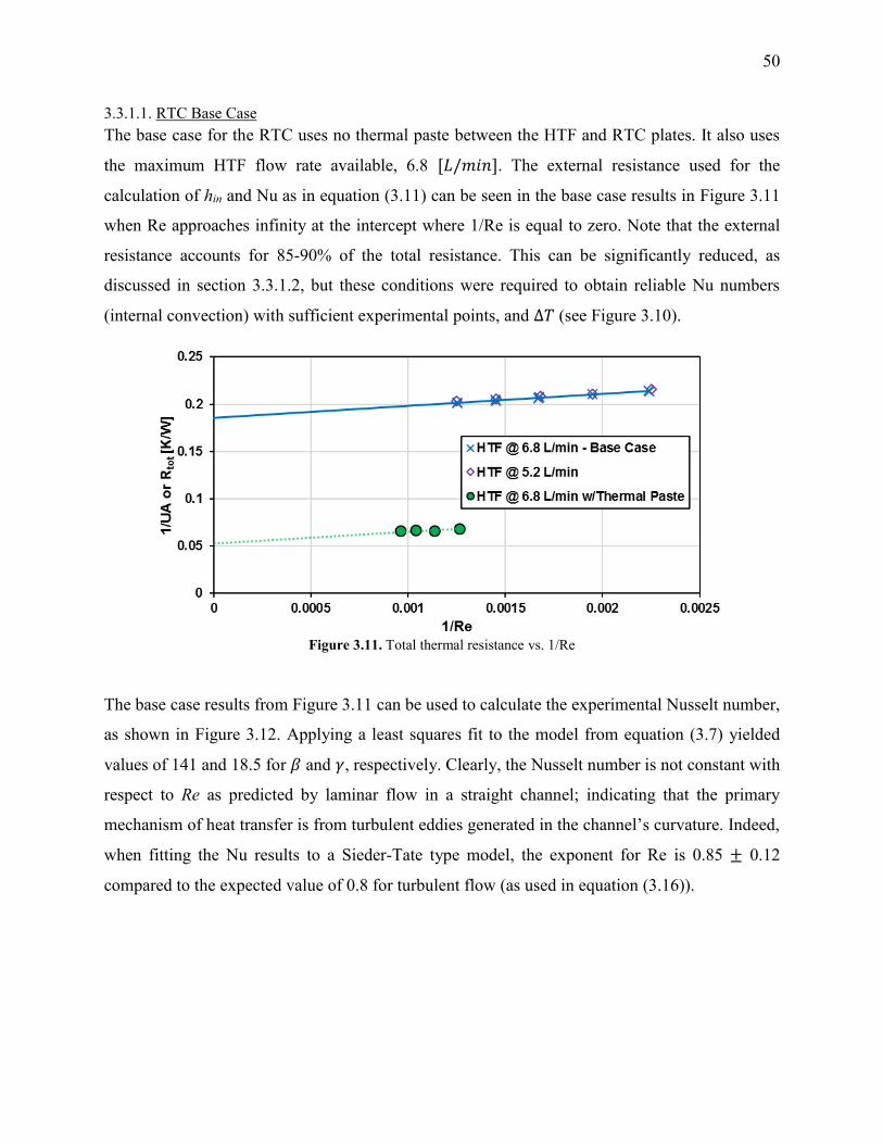
50
3.3.1.1. RTC Base Case
The base case for the RTC uses no thermal paste between the HTF and RTC plates. It also uses
the maximum HTF flow rate available, 6.8 [𝐿/𝑚𝑖𝑛]. The external resistance used for the
calculation of hin and Nu as in equation (3.11) can be seen in the base case results in Figure 3.11
when Re approaches infinity at the intercept where 1/Re is equal to zero. Note that the external
resistance accounts for 85-90% of the total resistance. This can be significantly reduced, as
discussed in section 3.3.1.2, but these conditions were required to obtain reliable Nu numbers
(internal convection) with sufficient experimental points, and ∆𝑇 (see Figure 3.10).
Figure 3.11. Total thermal resistance vs. 1/Re
The base case results from Figure 3.11 can be used to calculate the experimental Nusselt number,
as shown in Figure 3.12. Applying a least squares fit to the model from equation (3.7) yielded
values of 141 and 18.5 for 𝛽 and 𝛾, respectively. Clearly, the Nusselt number is not constant with
respect to Re as predicted by laminar flow in a straight channel; indicating that the primary
mechanism of heat transfer is from turbulent eddies generated in the channel’s curvature. Indeed,
when fitting the Nu results to a Sieder-Tate type model, the exponent for Re is 0.85 ± 0.12
compared to the expected value of 0.8 for turbulent flow (as used in equation (3.16)).

51
Figure 3.12. Nusselt number (experimental and predicted) vs. Reynolds number for the 320b RTC
3.3.1.2. Reduction of External Resistances in the FlowPlate®
This reactor’s technology was designed to minimize the external heat transfer resistance so that
the main contribution comes from the internal resistance to convection. One approach is to operate
with a large excess of thermal fluid in an isolated loop to minimize thermal losses. The intention
is not optimized heat exchange efficiencies in a counter-current mode, but rather a rapid
temperature homogenisation to avoid localized hot spot formation due to reactions. In such a case,
the design of the thermal fluid channel did not need to be micro-structured but was instead designed
for operation in the turbulent regime to maximize heat transfer capability. The typical Re number
(with water as HTF and flow rate of 6.8 [𝐿/𝑚𝑖𝑛]) is 15000. The HTF channel geometry of the
FlowPlate® A6 or A5 is intended to be used for the delivery of thermal fluid from major laboratory
brand of cryostats (Huber, Julabo, etc.). The HTF plates have the additional advantage of using
aluminum or copper (high 𝑘 metals) because the chemical compatibility is not an issue as in the
reactor plates (which use Hastelloy® C22).
As previously noted, the external resistance was relatively high compared to the internal resistance
to convection. To ensure 𝑅𝑐𝑜𝑛𝑣,𝑜𝑢𝑡 is minimized, the HTF flow rate must be increased towards
infinity; however, the thermal bath was already operating at maximum flow rate (6.8 [𝐿/𝑚𝑖𝑛]).
To determine if the external convective resistance had a significant effect on 𝑅𝑒𝑥𝑡, the thermal
fluid flow rate was decreased to 5.2 [𝐿/𝑚𝑖𝑛]. If reducing the HTF flow raised the total resistance
compared to tests with the maximum flow rate, it would indicate that 𝑅𝑐𝑜𝑛𝑣,𝑜𝑢𝑡 still represents a

52
significant portion of 𝑅𝑡𝑜𝑡. Figure 3.11 shows that reducing the HTF flow rate had a negligible
effect on the total resistance, and 𝑅𝑐𝑜𝑛𝑣,𝑜𝑢𝑡 can be considered marginal for these operating
conditions.
A silver-based thermal paste was applied between the reactor and heat transfer plates to fill any
voids with highly conductive paste to reduce the contact resistance between the plates. When
performing these tests, the observed UAHE was around 15 [𝑊/𝐾], leading to a U of 2200
[𝑊 (𝑚2 𝐾)⁄ ] when using the internal area available for heat transfer from Table 3.2. Note that
almost all the flow rates tested resulted in the internal fluid reaching thermal equilibrium with the
HTF before the outlet, as seen in Figure 3.10, meaning they cannot be used in the Nusselt number
analysis. However, the silver-based thermal paste evidently reduced the external resistance by
around 70% with the few points that could be studied in Figure 3.11, and thermal paste will
substantially increase the rate of heat transfer between the plates. Indeed, if you were to use the
same slope as the base-case results (where there was enough resolution to measure the internal
convection), the external resistance is estimated to be 0.05 [𝐾/𝑊] in these tests. Though this
resistance, which is basically the sum of material and remaining contact resistances still contributes
to ca. 80% of the overall resistance to heat transfer under the flow rate studied. The next section
will introduce a test reaction that can further study this aspect.
3.3.2. Test Reaction to Study Localized Heat Transfer
The Grignard-type homogenous synthesis of methyl 2-oxobutanoate (2-MOB, 3) from dimethyl-
oxalate (DMO, 1) and ethylmagnesium chloride (2) was used to test several plate reactors. Since
the reaction yield is such a strong function of temperature, it is a useful test reaction for
understanding localized heat transfer. First, tests were performed in the 240 plate with either one
or two injection points to demonstrate the Grignard reaction’s high sensitivity to temperature
hotspots along the length of the channel. Since there are competitive reactions that are favoured at
higher temperatures, it is important to keep the temperature as low as possible. This can be
challenging due to the exothermic nature and very fast kinetics of the reaction, causing hotspots to
form in the mixing zone of the injection points. Figure 3.13 clearly shows that reducing the local
concentration of one reactant by injecting it at two points along the channel length increases the
overall yield versus one single addition at the plate reactor inlet. In previous work, we have
demonstrated that this effect is not a contribution of better mixing but that it is essential to return

53
the fluid temperature near the sink level of the thermal fluid before the next injection point [11].
With half of the reactant available, the total heat released near the inlet is about halved, favouring
the main reaction over its competitive reaction to produce 5 or 7 from Figure 3.7.
Figure 3.13. Effect of multi-injection for Grignard Reaction
The temperature effect itself can be observed when comparing the same reaction at multiple
temperatures for two different plates. Shown in Figure 3.14, the reactions with lower overall
temperatures resulted in higher yields. Although two separate plates were used with different
dimensions, the 10°C temperature changes resulted in a similar difference in yield, but the main
factor to control yield remains the multi-injection approach.
Note that the product yield is only slightly positively correlated with flow rate for the range studied
since various counteracting factors are involved. Assuming the reaction is fully mixing controlled,
four cases can be depicted: (1) an increase of flow rate favors mixing via higher energy dissipation
rate leading to better selectivity (higher yield) for reactions encompassing parallel-consecutive
pathways; (2) better mixing also means reagents react in a shorter time (i.e. in a smaller flow path),
releasing the heat in a more confined volume which intensifies the hot spot (lowering the yield);
(3) the increase of flow rate also increases the reaction heat intensity (power) leading to a larger
hot spot; (4) this effect is however somehow counteracted by the decrease of internal heat
resistance. It is this sensitive impact of temperature on selectivity that allows this reaction to be a
useful tool for the detection of hotspots in reactors.
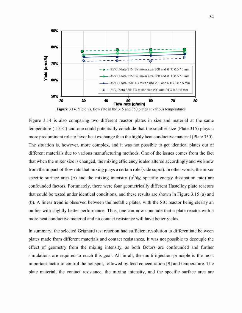
54
Figure 3.14. Yield vs. flow rate in the 315 and 350 plates at various temperatures
Figure 3.14 is also comparing two different reactor plates in size and material at the same
temperature (-15°C) and one could potentially conclude that the smaller size (Plate 315) plays a
more predominant role to favor heat exchange than the highly heat conductive material (Plate 350).
The situation is, however, more complex, and it was not possible to get identical plates out of
different materials due to various manufacturing methods. One of the issues comes from the fact
that when the mixer size is changed, the mixing efficiency is also altered accordingly and we know
from the impact of flow rate that mixing plays a certain role (vide supra). In other words, the mixer
specific surface area (𝑎) and the mixing intensity (u3/dh; specific energy dissipation rate) are
confounded factors. Fortunately, there were four geometrically different Hastelloy plate reactors
that could be tested under identical conditions, and these results are shown in Figure 3.15 (a) and
(b). A linear trend is observed between the metallic plates, with the SiC reactor being clearly an
outlier with slightly better performance. Thus, one can now conclude that a plate reactor with a
more heat conductive material and no contact resistance will have better yields.
In summary, the selected Grignard test reaction had sufficient resolution to differentiate between
plates made from different materials and contact resistances. It was not possible to decouple the
effect of geometry from the mixing intensity, as both factors are confounded and further
simulations are required to reach this goal. All in all, the multi-injection principle is the most
important factor to control the hot spot, followed by feed concentration [9] and temperature. The
plate material, the contact resistance, the mixing intensity, and the specific surface area are

55
additional factors with less importance that control the extent (peak magnitude and broadness) of
the hot spot.
Figure 3.15. (a) Average Grignard reaction yield (at -15 °C) vs. mixer specific area for heat transfer, and (b)
Grignard reaction yield (at -15 °C) vs. specific energy dissipation rate (u3/dh)
3.3.3. Case Studies on Plate Reactor Heat Transfer Capabilities
The purpose of this study was to evaluate the micro-reactors for applications requiring significant
heat removal/addition for exo/endothermal reactions. The enhanced wall-to-fluid heat transfer
rates provided by micro-reactors’ high area-to-volume ratio enable reactions that generate or
consume large amounts of heat and the use of more concentrated reactants while greatly reducing
the potential of a thermal runaway. The thermal control performance of a reactor as a whole can
be expressed using the fourth Damköhler number, 𝐷𝑎𝐼𝑉 in equation (3.15). This dimensionless
number represents the ratio of heat generation, calculated from the reaction rate 𝑟, the reaction
enthalpy ∆𝐻𝑅 and the reactor volume 𝑉𝑅, to heat transfer in the reactor, calculated from the overall
heat transfer coefficient 𝑈, the total area for heat transfer, 𝐴𝐻𝐸 , and the temperature driving force
(|𝑇 - 𝑇𝑇𝐹|) between the reactive media and thermal fluid used to control the temperature. This
number considers all the parameters necessary to optimize the heat transfer in a system. To be
satisfactory, this ratio is ideally smaller than one.
50%
60%
70%
80%
1 10
Yie
ld [
are
a%
]
Mixer Specific Area [mm2/mm3]
Hastelloy Plate 260: TG mixer size 100
Hastelloy Plate 240: TG mixer size 200
SiC Plate 350: TG mixer size 200
Hastelloy Plate 215: SZ mixer size 200
Hastelloy Plate 315: SZ mixer size 300
All Hastelloy Plates
SiC
(a)
60%
70%
80%
0.0001 0.01 1 100
Yie
ld [
are
%]
u3/dh [m2/s3](b)
𝐷𝑎𝐼𝑉 =
𝑞𝑟𝑥𝑛
𝑞𝐻𝐸=
|𝑟∆𝐻𝑅| ∙ 𝑉𝑅
𝑈𝐴𝐻𝐸(|𝑇 − 𝑇𝑇𝐹|)≪ 1
(3.15)
56
For a given reaction, this can be achieved independently of the reactor scale by lowering the
reaction rate using diluted solutions and/or colder temperatures, but these options go against the
philosophy of process intensification, and a particular temperature or concentration may be
required for yield optimisation. Alternatively, the temperature of the thermal fluid can be adjusted,
but this cannot realistically impact 𝐷𝑎𝐼𝑉 by much more than one order of magnitude.
The remaining parametric options, 𝑈, 𝐴𝐻𝐸 and 𝑉𝑅, all vary with scale. As discussed, the overall
heat transfer coefficient is a function of the internal convective resistance to heat transfer as well
as the external resistances in the system (metallic wall conductive and contact resistances, and
thermal fluid side convective resistance), which are impacted more so by the system setup rather
than scale. The reactor side convection coefficient, ℎ𝑖𝑛, will not vary greatly with the scale-up as
shown in equations (3.16) (a Sieder-Tate-like model that was fit with the results from Figure 3.12)
and (3.17). Note that the ratio Q2/Q1 of equation (3.17) is changed into a hydraulic diameter ratio
using the 3/7th scale-up rule based on constant energy dissipation rate (휀) [12].
ℎ𝑖𝑛 = 𝑁𝑢𝑖𝑛
𝑘
𝐷ℎ
= 𝐴 ∙ 𝑅𝑒𝑖𝑛0.85 ∙ 𝑃𝑟0.33 ∙
𝑘
𝐷ℎ (3.16)
ℎ𝑖𝑛,2
ℎ𝑖𝑛,1∝ (
𝑅𝑒𝑖𝑛,2
𝑅𝑒𝑖𝑛,1)
0.85
(𝐷ℎ,1
𝐷ℎ,2) = (
𝑄2
𝑄1∙
𝐷ℎ,1
𝐷ℎ,2)
0.85
(𝐷ℎ,1
𝐷ℎ,2) = ((
𝐷ℎ,2
𝐷ℎ,1)
73
)
0.85
(𝐷ℎ,1
𝐷ℎ,2)
1.85
= (𝐷ℎ,2
𝐷ℎ,1)
73
(0.85)−1.85
≈ 1 (3.17)
The ratio between the area available for heat transfer, 𝐴𝐻𝐸 , and the reactor volume, 𝑉𝑅, is
dependent solely on the 𝐷ℎ of the channels as shown in equations (3.18) and (3.19).
𝐷ℎ =2𝑑𝑤
𝑑 + 𝑤 (3.18)
𝐴𝐻𝐸
𝑉𝑅=
2(𝑑 + 𝑤)𝑙
𝑑𝑤𝑙=
4
𝐷ℎ
(3.19)
Using the thermal paste case with the 320B RTC; Figure 3.11 shows that the overall heat transfer
coefficient, U, is roughly equal to 2200 [𝑊 (𝑚2 𝐾)⁄ ]. A common heat exchanger design heuristic
[29] uses 10 K as the minimum approach temperature, |𝑇 − 𝑇𝑡𝑓|. Using this value, is possible to
plot the 𝐷𝑎𝐼𝑉 as a function of the hydraulic diameter for various volumetric heat generation rate
𝑟∆𝐻𝑅. The 𝐷𝑎𝐼𝑉 of four case studies are evaluated and discussed below. Each case can be
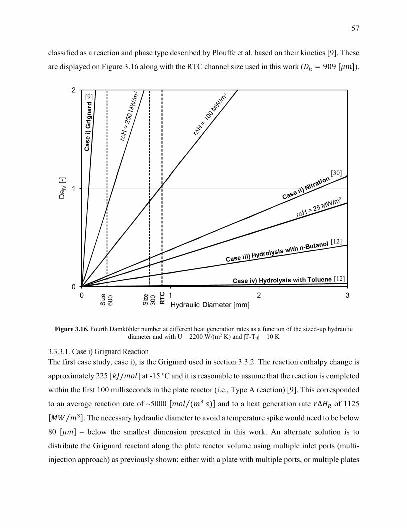
57
classified as a reaction and phase type described by Plouffe et al. based on their kinetics [9]. These
are displayed on Figure 3.16 along with the RTC channel size used in this work (𝐷ℎ = 909 [𝜇𝑚]).
Figure 3.16. Fourth Damköhler number at different heat generation rates as a function of the sized-up hydraulic
diameter and with U = 2200 W/(m2 K) and |T-Ttf| = 10 K
3.3.3.1. Case i) Grignard Reaction
The first case study, case i), is the Grignard used in section 3.3.2. The reaction enthalpy change is
approximately 225 [𝑘𝐽/𝑚𝑜𝑙] at -15 oC and it is reasonable to assume that the reaction is completed
within the first 100 milliseconds in the plate reactor (i.e., Type A reaction) [9]. This corresponded
to an average reaction rate of ~5000 [𝑚𝑜𝑙 (𝑚3 𝑠)⁄ ] and to a heat generation rate 𝑟∆𝐻𝑅 of 1125
[𝑀𝑊 𝑚3⁄ ]. The necessary hydraulic diameter to avoid a temperature spike would need to be below
80 [𝜇𝑚] – below the smallest dimension presented in this work. An alternate solution is to
distribute the Grignard reactant along the plate reactor volume using multiple inlet ports (multi-
injection approach) as previously shown; either with a plate with multiple ports, or multiple plates
0
1
2
0 1 2 3
Da
IV[-
]
Hydraulic Diameter [mm]Siz
e6
00
Siz
e3
00
RT
C
[9]
[30]
[12]
[12]
58
in series. This multi-injection approach is of course also possible with conventional technology
(i.e., not micro-structured) but with reduced process intensification capabilities.
3.3.3.2. Case ii) Nitration
The second case study, ii), is the homogenous nitration of salicylic acid using a solution of acetic
and nitric acid. The experimental details are described again in [9]; the reaction needs to be
operated at 65 oC or above to avoid delays associated with the auto-catalytic behaviour of the
reaction. At this temperature, the reaction rate was estimated to be ~230 [𝑚𝑜𝑙 (𝑚3 𝑠)⁄ ] (type B),
and the reaction enthalpy is 146 [𝑘𝐽/𝑚𝑜𝑙][30], which yielded a heat generation rate of 33
[𝑀𝑊 𝑚3⁄ ]. This is sufficiently low to be operated in micro-reactors, but not necessarily in milli-
structures with internal diameters greater than 2.5 [𝑚𝑚]. Upon scale-up, it would then be best to
use an adaptive channel design starting at a small size where the reactants meet and where the heat
generation is high, and progressing into larger channels as the reaction rate decreases, i.e.,
maintaining the value 𝑟𝑉𝑅
𝐴𝐻𝐸 constant (multi-scale approach). Typically, a plate with a channel depth
starting in the micrometer domain will be selected and increased in size until conventional and
readily available heat transfer technology can be used.
3.3.3.3. Cases iii) and iv) Two-Phase Hydrolysis
The third and fourth case studies are the liquid-liquid hydrolysis reaction commonly utilized for
the characterization of micro-reactors for liquid-liquid mass transfer [12,31–36]. While the
hydrolysis step itself is not highly exothermic, it is followed by two neutralization steps that result
in an overall enthalpy change of about 112 [𝑘𝐽/𝑚𝑜𝑙]. The cases here considered the use of a 0.5
mol/L solution of the acetate in drop flow operated at an energy dissipation rate of ~100 [𝑚2 𝑠3⁄ ].
Under homogenous conditions, the initial reaction rate would be 3500 [𝑚𝑜𝑙 (𝑚3𝑠)⁄ ] (type A) and
the total heat release rate at around 390 [𝑀𝑊 𝑚3⁄ ]. However, these liquid-liquid cases have the
distinction of being interphase mass transfer limited, which reduces the observed reaction rate, 𝑟.
The rate constant is instead equal to the dispersed phase overall volumetric mass transfer
coefficient.
Case iii) analyzes the use of n-butanol as the organic solvent. At these conditions, the coefficient
𝐾𝑑𝑎 was 2.22∙10-1 [𝑠−1] [12], which would result in an initial reaction rate of ~110 [𝑚𝑜𝑙 (𝑚3 𝑠)⁄ ]
and a heat generation rate 𝑟∆𝐻𝑅 of 12.5 [𝑀𝑊 𝑚3⁄ ]. Clearly, the results indicate that a micro-
59
structure is no longer needed for the control of reaction heat (as it is safe to operate at a 𝐷ℎ below
7 [𝑚𝑚]), but rather to increase the rate of mass transfer to increase the overall rate of reaction.
The fourth case considers the use of toluene instead of butanol as the organic solvent. In such case,
the coefficient 𝐾𝑑𝑎 is reduced to 1.66∙10-2 [𝑠−1] [12] and the heat generation rate 𝑟∆𝐻𝑅 to 0.9
[𝑀𝑊 𝑚3⁄ ].
Low heat generation rates such as in case iv) can be safely operated in a channel with internal
diameters below 90 [𝑚𝑚]. However, under the flow rates studied in this work, the energy
dissipation rate in such a large reactor would be very low and the system even more mass transfer
limited. The use of a micro-reactor for fast liquid-liquid reactions was necessary to obtain
interphase mass transfer rates that are greater than what would be achieved in larger reactor.
Even at high energy dissipation rates using toluene, the acetate hardly transferred to the aqueous
phase due to its affinity with the organic solvent (demonstrated by its high partition coefficient
HA). Consequently, large residence times are still needed and cannot realistically be achieved in
micro-reactors within reasonable pressure drops. For example, at energy dissipations rates of 100
[𝑚2 𝑠3⁄ ], the overall volumetric mass transfer coefficient 𝐾𝑑𝑎 with toluene was such that to obtain
a conversion of 90%, a residence time of about 60 seconds would be needed and would result in a
pressure drop of 60 [𝑏𝑎𝑟] (∆𝑃 = 𝜌휀𝜏) [12].
In such cases and when heat transfer is not limiting, reactors combining larger channels with an
active mixing technique might present the best solution. Active mixing techniques use an external
source of energy to agitate the fluids such as mechanical actuators. The energy dissipation rates
that can be achieved are generally independent of the overall flow rates, and thus high values can
be obtained at the same time as large residence times and low pressure drops. The use of pulsating
flow in reactors with baffles [37] or without [38] have been proven to be useful tools in these cases.
3.4. Conclusions
Non-reactive heat transfer experiments were performed in the A6-sized FlowPlate® system
manufactured by Ehrfeld Mikrotechnik BTS. For a residence time channel with Reynolds numbers
ranging from 400-2000, the internal Nusselt number was fit to a Gnielinski-like model. This was
deemed appropriate due to the curvature in the channels. The channel’s curvature could form
chaotic eddies at relatively low Reynolds numbers, which agreed with the observed friction factor
60
results. The Nusselt number also correlated with Reynolds to the power of 0.85 ± 0.12, which is
similar to that of the turbulent Sieder-Tate correlation (0.8); further confirming the use of a model
in transitional/turbulent flow over laminar flow. The external resistances to heat transfer were also
studied in this system; specifically, the HTF flow rate and the contact resistance between the HTF
plate and RTC plate. The largest contributor to the resistance of heat transfer was shown to be the
contact resistance, which could significantly reduce the external resistance (by approximately
70%) using a silver-based thermal paste.
A test reaction, the synthesis of methyl 2-oxobutanoate using dimethyl-oxalate and the Grignard
reagent ethylmagnesium chloride, was also presented as a means to differentiate localized heat
transfer characteristics in various micro-mixer shapes, materials, injection ports, and scales. Due
to the fast reaction kinetics, high exothermicity, and the increased selectivity for the desired
product at lower temperatures, this reaction allows for a semi-quantitative comparison of hotspot
formation in different plate reactors when comparing total yields. It was shown that the Grignard
reaction can be used as a sensitive tool to compare different reactors when the specific heat transfer
parameters are not fully known. As predicted by heat transfer theory, a multi-injection approach
was the most effective method for reducing the magnitude of hotspot formation, thereby increasing
the reaction yield. Additionally, increasing the specific area of a mixer geometry led to higher
yields due to increased wall-to-fluid heat transfer.
Lastly, four case studies were analyzed based on the fourth Damköhler number to evaluate what
maximum channel diameter would allow sufficient heat removal based on the overall heat transfer
coefficients found experimentally. With a known reaction rate and heat of reaction, it is possible
to select a suitable channel size. This analysis is a useful addition to the toolbox developed by
Plouffe et al. [9] when selecting a proper reactor system for a given application.
3.5. Nomenclature
Symbols [𝑈𝑛𝑖𝑡𝑠] General
𝑎 Specific area (single phase) or specific interfacial area (biphasic) [𝑚2/𝑚3] 𝐴𝐻𝐸 Area available for heat transfer [𝑚2] 𝑐 Empirical constant for calculation of thermal developing region [−] 𝑐𝑝 Heat capacity of fluid [𝐽/(𝑘𝑔 𝐾)]
𝑑 Contraction depth [𝑚] 𝐷ℎ Hydraulic diameter at contraction (2𝑤𝑑/(𝑤 + 𝑑)) [𝑚]

61
𝐷𝑎𝐼𝑉 Damköhler Number [−] 𝐷𝑛 Dean number [−] 𝑓 Friction factor (Darcy–Weisbach definition) [−] 𝑓𝑐 Chaotic term in friction factor [−] 𝑓𝑙 Laminar term in friction factor [−] ℎ Local convective heat transfer coefficient [𝑊/(𝑚2𝐾)] 𝐻𝐴 organic/aqueous concentration distribution coefficient [−] Δ𝐻𝑟 Reaction enthalpy change [𝐽/𝑚𝑜𝑙] 𝐻𝑇𝐹 Heat Transfer Fluid
𝑘 Thermal conductivity [𝑊/(𝑚 𝐾)] 𝐾𝑑 Overall convective mass transfer coefficient (m/s) [𝑚/𝑠] 𝑙 Reactor Length [𝑚] �� Mass flow rate [𝑘𝑔/𝑠] 𝑀𝑇𝑅 Mix-Then-Reside Reactor
𝑁𝑢 Nusselt Number [−] Δ𝑃 Pressure loss across reactor length [𝑃𝑎] 𝑃𝑟 Prandtl Number [−] 𝑞 Heat Transferred [𝑊] 𝑄 Volumetric flow rate [𝑚3/𝑠] 𝑟 Reaction rate [𝑚𝑜𝑙/𝑠] 𝑅𝑐 Radius of Curvature [𝑚] 𝑅𝑐𝑜𝑛𝑑 Resistance to heat transfer via conduction [𝐾/𝑊] 𝑅𝑐𝑜𝑛𝑡𝑎𝑐𝑡 Resistance to heat transfer via contact between the plates [𝐾/𝑊] 𝑅𝑐𝑜𝑛𝑣 Resistance to heat transfer via convection [𝐾/𝑊] 𝑅𝑒𝑥𝑡 External resistance to heat transfer [𝐾/𝑊] 𝑅𝑡𝑜𝑡 Total resistance to heat transfer in the system [𝐾/𝑊] 𝑅𝑒 Reynolds Number [−] 𝑅𝑇𝐶 Residence Time Channel
𝑇 Temperature [°𝐶 𝑜𝑟 𝐾] 𝑡 Wall thickness [𝑚] 𝑇𝐺 Tangential Mixer
𝑢 Superficial velocity of the fluid at the contraction [𝑚/𝑠] 𝑈 Overall heat transfer coefficient [𝑊/(𝑚2 𝐾)] 𝑉 Volume [𝑚3] 𝑤 Contraction width [𝑚]
Greek Symbols
𝛼 Aspect ratio (𝑤/𝑑) [−] 𝛽 1st fitted parameter for Gnielinski-type model [−] 𝛾 2nd fitted parameter for Gnielinski-type model [−] 휀 Average rate of energy dissipation (∆𝑃 𝜌𝜏⁄ ) [𝑚2/𝑠3] 𝜇 Dynamic viscosity [𝑃𝑎 𝑠] 𝜌 Density [𝑘𝑔/𝑚3] 𝜏 Average residence time [𝑠]
62
Subscripts
1,2 Two different scales
𝑐 Cold stream
𝐷𝐵 Dittus-Boelter
𝑓 Fluid
𝐺𝑛 Gnielinski
ℎ Hot stream
𝐻𝐸 Heat exchange
𝑖 Measured at inlet
𝑖𝑛 Inner channel side (in this case RTC or MTR side)
𝐿𝑀 Log mean
𝑀𝐸 Mixing Element
𝑜 Measured at outlet
𝑜𝑢𝑡 Outer channel side (in this case HTF side)
𝑅 Reactor side
𝑟𝑥𝑛 Reaction
𝑠 Conditions at the wall surface
𝑆𝑇 Sieder-Tate
𝑇𝐹 Transfer fluid
𝑡𝑜𝑡 Total
𝑤 across the wall
Acknowledgements. The authors would like to thank the Natural Sciences and Engineering
Research Council of Canada, including the CREATE program in Continuous Flow Science, and
Lonza AG for their financial contribution. Also, Ehrfeld Mikrotechnik BTS is acknowledged for
the reactor manufacturing.
3.6. References
[1] N.-T. Nguyen, Z. Wu, Micromixers—a review, J. Micromechanics Microengineering. 15
(2005) R1–R16. doi:10.1088/0960-1317/15/2/R01.
[2] M.N. Kashid, L. Kiwi-Minsker, Microstructured Reactors for Multiphase Reactions: State
of the art, Ind. Eng. Chem. Res. 48 (2009) 6465–6485. doi:10.1021/ie8017912.
[3] N. Kockmann, M. Gottsponer, D.M. Roberge, Scale-up concept of single-channel
microreactors from process development to industrial production, Chem. Eng. J. 167
(2011) 718–726. doi:10.1016/j.cej.2010.08.089.
[4] V. Kumar, M. Paraschivoiu, K.D.P. Nigam, Single-phase fluid flow and mixing in
microchannels, Chem. Eng. Sci. 66 (2011) 1329–1373. doi:10.1016/j.ces.2010.08.016.
[5] N. Kockmann, D.M. Roberge, Scale-up concept for modular microstructured reactors
based on mixing, heat transfer, and reactor safety, Chem. Eng. Process. Process Intensif.
50 (2011) 1017–1026. doi:10.1016/j.cep.2011.05.021.
[6] P.S. Lee, S. V. Garimella, Thermally developing flow and heat transfer in rectangular
63
microchannels of different aspect ratios, Int. J. Heat Mass Transf. 49 (2006) 3060–3067.
doi:10.1016/j.ijheatmasstransfer.2006.02.011.
[7] S. Kandlikar, S. Garimella, D. Li, S. Colin, M.R. King, Heat Transfer and Fluid Flow in
Minichannels and Microchannels, 2nd ed., Elsevier Ltd., Kidlington, Oxford, 2014.
doi:10.1016/B978-0-08-098346-2.00003-X.
[8] I. Rossetti, M. Compagnoni, Chemical reaction engineering, process design and scale-up
issues at the frontier of synthesis: Flow chemistry, Chem. Eng. J. 296 (2016) 56–70.
doi:10.1016/j.cej.2016.02.119.
[9] P. Plouffe, A. Macchi, D.M. Roberge, From batch to continuous chemical synthesis-a
toolbox approach, Org. Process Res. Dev. 18 (2014) 1286–1294. doi:10.1021/op5001918.
[10] P. Barthe, C. Guermeur, O. Lobet, M. Moreno, P. Woehl, D.M. Roberge, et al.,
Continuous multi-injection reactor for multipurpose production - Part I, Chem. Eng.
Technol. 31 (2008) 1146–1154. doi:10.1002/ceat.200800132.
[11] D.M. Roberge, N. Bieler, M. Mathier, M. Eyholzer, B. Zimmermann, P. Barthe, et al.,
Development of an industrial multi-injection microreactor for fast and exothermic
reactions - Part II, Chem. Eng. Technol. 31 (2008) 1155–1161.
doi:10.1002/ceat.200800131.
[12] P. Plouffe, M. Bittel, J. Sieber, D.M. Roberge, A. Macchi, On the scale-up of micro-
reactors for liquid–liquid reactions, Chem. Eng. Sci. 143 (2016) 216–225.
doi:10.1016/j.ces.2015.12.009.
[13] F.P. Incropera, D.P. DeWit, T.L. Bergman, A.S. Lavine, Fundamentals of Heat and Mass
Transfer, 7th ed., John Wiley & Sons, Inc., Jefferson City, 2011.
[14] G.L. Morini, Single-phase convective heat transfer in microchannels: A review of
experimental results, Int. J. Therm. Sci. 43 (2004) 631–651.
doi:10.1016/j.ijthermalsci.2004.01.003.
[15] M.E. Steinke, S.G. Kandlikar, Single-phase liquid heat transfer in microchannels, in: 3rd
Int. Conf. Microchannels Minichannels, 2005. doi:10.1115/ICMM2005-75114.
[16] W.M. Kays, M.E.E. Crawford, Convective Heat and Mass Transfer, 4th ed., McGraw-
Hill, Boston, 2005.
[17] N. Kockmann, Transport Phenomena in Micro Process Engineering, Springer Berlin
Heidelberg, Berlin, Heidelberg, 2008. doi:10.1007/978-3-540-74618-8.
[18] W.R. Dean, Note on the motion of fluid in a curved pipe, London, Edinburgh, Dublin
Philos. Mag. J. Sci. 4 (1927) 208–223.
[19] W.R. Dean, The stream-line motion of fluid in a curved pipe, London, Edinburgh, Dublin
Philos. Mag. J. Sci. 5 (1928) 673–695.

64
[20] F. Jiang, K.S. Drese, S. Hardt, M. Kupper, F. Schonfeld, Helical flows and chaotic
mixing in curved micro channels, AIChE J. 50 (2004) 2297–2305. doi:10.1002/aic.10188.
[21] F. Schönfeld, S. Hardt, Simulation of helical flows in microchannels, AIChE J. 50 (2004)
771–778. doi:10.1002/aic.10071.
[22] G. Gauthier, P. Gondret, H. Thomé, M. Rabaud, Centrifugal instabilities in a curved
rectangular duct of small aspect ratio, Phys. Fluids. 13 (2001) 2831–2834.
doi:10.1063/1.1400136.
[23] R.H. Perry, D.W. Green, J.O. Maloney, eds., Perry’s Chemical Engineers’ Handbook, 8th
ed., McGraw-Hill, New York, 2007.
[24] T.. Adams, M.. Dowling, S.. Abdel-Khalik, S.. Jeter, Applicability of traditional turbulent
single-phase forced convection correlations to non-circular microchannels, Int. J. Heat
Mass Transf. 42 (1999) 4411–4415. doi:10.1016/S0017-9310(99)00102-7.
[25] T.M. Adams, S.I. Abdel-Khalik, S.M. Jeter, Z.H. Qureshi, An experimental investigation
of single-phase forced convection in microchannels, Int. J. Heat Mass Transf. 41 (1998)
851–857. doi:10.1016/S0017-9310(97)00180-4.
[26] Haynes International, HASTELLOY® C-22® Alloy, (2015).
http://www.haynesintl.com/alloys/alloy-portfolio_/Corrosion-resistant-
Alloys/HASTELLOY-C-22-.aspx (accessed September 21, 2016).
[27] McMaster-Carr, Electrically and Thermally Conductive Grease, (2016).
http://www.mcmaster.com/#1219k59/ (accessed September 21, 2016).
[28] J. Patek, J. Hruby, J. Klomfar, M. Souckova, A.H. Harvey, Reference Correlations for
Thermophysical Properties of Liquid Water at 0.1 MPa, J. Phys. Chem. Ref. Data. 38
(2009) 21. doi:10.1063/1.3043575.
[29] J.R. Couper, W.R. Penney, J.R. Fair, S.M. Walas, Chemical Process Equipment:
Selection and Design, 3rd ed., Elsevier, Waltham MA, 2012.
[30] R. Andreozzi, M. Canterino, V. Caprio, I. Di Somma, R. Sanchirico, Batch salicylic acid
nitration by nitric acid/acetic acid mixture under isothermal, isoperibolic and adiabatic
conditions, J. Hazard. Mater. 138 (2006) 452–458. doi:10.1016/j.jhazmat.2006.05.104.
[31] B. Ahmed-Omer, D. Barrow, T. Wirth, Effect of segmented fluid flow, sonication and
phase transfer catalysis on biphasic reactions in capillary microreactors, Chem. Eng. J.
135 (2008) S280–S283. doi:10.1016/j.cej.2007.07.017.
[32] B. Ahmed, D. Barrow, T. Wirth, Enhancement of reaction rates by segmented fluid flow
in capillary scale reactors, Adv. Synth. Catal. 348 (2006) 1043–1048.
doi:10.1002/adsc.200505480.
[33] V.D. Parker, Instantaneous rate constants in physical organic chemistry: Application to
65
acyl transfer reactions of p-nitrophenyl acetate to hydroxide ion, J. Phys. Org. Chem. 19
(2006) 714–724. doi:10.1002/poc.1064.
[34] P. Plouffe, D.M. Roberge, A. Macchi, Liquid–liquid flow regimes and mass transfer in
various micro-reactors, Chem. Eng. J. 300 (2016) 9–19. doi:10.1016/j.cej.2016.04.072.
[35] P. Plouffe, D.M. Roberge, J. Sieber, M. Bittel, A. Macchi, Liquid–liquid mass transfer in
a serpentine micro-reactor using various solvents, Chem. Eng. J. 285 (2016) 605–615.
doi:10.1016/j.cej.2015.09.115.
[36] E. Mielke, D.M. Roberge, A. Macchi, Microreactor mixing-unit design for fast liquid—
liquid reactions, J. Flow Chem. 6 (2016) 279–287. doi:10.1556/1846.2016.00026.
[37] J.R. McDonough, A.N. Phan, A.P. Harvey, Rapid process development using oscillatory
baffled mesoreactors – A state-of-the-art review, Chem. Eng. J. 265 (2015) 110–121.
doi:10.1016/j.cej.2014.10.113.
[38] S.S. Mongeon, D.M. Roberge, M. Bittel, P. Elsner, A. Macchi, Liquid–Liquid Mass
Transfer in an Oscillatory-Flow Mesoscale Coil Reactor without Baffles, Org. Process
Res. Dev. (2016) acs.oprd.5b00356. doi:10.1021/acs.oprd.5b00356.

66
4. Conclusions and Future Work
4.1. Conclusions
The “toolbox” developed by Plouffe et al. [1] can be useful in properly selecting a reactor for a
broad set of conditions such as reaction rate (fast, moderate, slow) and phase properties
(homogenous, liquid-liquid, liquid-gas, gas-solid, etc.). The work presented here provides
detailed insight when selecting reactors specifically for fast liquid-liquid reactions, or for highly
exothermic reactions, where micro-reactors could be employed to enhance the transport
properties of a fluid system.
In section 2, several obstacle-based micro-mixer geometries were investigated with up to four
different solvent-pair systems for two different mixer scales. The liquid-liquid systems were
visually classified based on some combination of the following flow regimes: slug flow; parallel
flow; or drop flow. The drop flow regime has the highest specific area available for interphase
mass transfer and is, therefore, ideal for applications in fast liquid-liquid reactions. Using the
alkaline hydrolysis of 4-nitrophenyl acetate as a test reaction, the overall volumetric mass transfer
coefficient (Korga) could be measured analytically. The Korga was plotted vs. the average rate of
energy dissipation (휀) to determine the most efficient mixer design (i.e., the mixer with the earliest
onset of drop flow). In the flow range of 1-20 mL/min, the novel LL-Triangle micro-mixer design
was shown to perform equally well or better in all solvent-pairs investigated than any of the other
micro-mixers studied: the Sickle, the LL-Rhombus, and the LL-Empty. The LL-Triangle was most
clearly superior to the other geometries at low flow rates for low interfacial tension systems, such
as n-butanol-water, where the drop flow regime was observed at the lowest energy dissipation,
and the unwanted parallel flow regime was avoided altogether.
The same results were seen in a larger scale LL-Triangle where drop flow was achieved for all
flow rates studied (10-150 mL/min) in n-butanol-water. The overall volumetric mass transfer
coefficients were similar to those obtained at equal energy dissipations in the smaller scale in the
drop flow regime; confirming the “3/7th” scale-up rule. Thus, the LL-Triangle is an excellent tool
for the purpose of process development and scale-up of novel fast liquid-liquid reactions.
Heat transfer properties were then examined in section 3 for a FlowPlate® system by Ehrfeld
Mikrotechnik BTS, using both non-reactive and reactive techniques. In the non-reactive system
67
in section 3.1, the Nusselt Number was fit to a Gnielinski-type model for a serpentine rectangular
channel for 400 < 𝑅𝑒 < 2000. The use of a transitional model (from laminar to turbulent flow)
was deemed appropriate for such low Re due to the formation of chaotic eddies from the curvature
(Dean vortices). In addition to understanding the internal heat transfer coefficients, the external
resistances to heat transfer were tested; specifically, the heat transfer fluid (HTF) flow rate and the
contact resistance between the HTF plate and reactor plate. The largest contributor to the
resistance of heat transfer was shown to be the contact resistance, which could significantly reduce
the external resistance (by approximately 70%) using a silver-based thermal paste.
The synthesis of methyl 2-oxobutanoate using dimethyl-oxalate and the Grignard reagent
ethylmagnesium chloride was then presented in section 3.2 as a test reaction to differentiate
localized heat transfer characteristics in various micro-reactors. The reaction’s fast reaction
kinetics, high exothermicity, and the increased selectivity for the desired product at lower
temperatures allow for a semi-quantitative comparison of hotspot formation in different plate
reactors (e.g., various micro-mixer geometries, materials, injection ports, and channel scales) when
comparing total yields. A multi-injection approach was the most effective method for reducing
the magnitude of the hotspot, thereby increasing the reaction yield. Additionally, micro-mixers
with higher specific area had higher yields due to increased wall-to-fluid heat transfer.
Finally, section 3.3 considered four case studies which calculated the maximum channel diameter
that would allow sufficient heat removal based on the overall heat transfer coefficients found
experimentally (in section 3.1) and the fourth Damköhler number. The first case involved the
Grignard reaction from section 3.2, while the second case considered an auto-catalytic nitration
reaction. The third and fourth cases looked at the kinetics of the mass transfer limited hydrolysis
reaction (used in section 2) for n-butanol-water and toluene-water systems, respectively. This
section was presented as a tool (to add to the toolbox from Plouffe et al.) to select suitable channel
dimensions to ensure adequate heat transfer properly.
4.2. Future Work
While the work presented in this thesis has highlighted a novel micro-mixer geometry for liquid-
liquid reactions as well as various techniques for understanding heat transfer in micro-reactor
68
systems, several prospects for extending the scope of this project remain. The following studies
are recommended:
• Attempt other multiphase flow in the LL-Triangle micro-mixer. Determine if it can be used to
control the particle size distribution of a precipitation reaction (without plugging), or to
disperse a gas in a liquid.
• Use a high-speed, high-resolution camera to fully understand the various flow regimes in
the micro-mixers for different interfacial tensions and how dead zones (if any) form.
• Perform tracer experiments to obtain residence time distributions in the different reactors
to determine if the reactors can be considered truly “plug flow”.
• Perform multi-phase heat transfer experiments with the mixer geometries from section 2
to study the effect of flow regime on the wall-to-fluid heat transfer.
• Obtain the kinetic data for the Grignard reaction from section 3.2 to simulate and detail
the effect of flow rate on the product yield. This would allow for the fully quantitative
analysis of hotspot formation in various micro-reactors.
4.3. References
[1] P. Plouffe, A. Macchi, D.M. Roberge, From Batch to Continuous Chemical Synthesis—A
Toolbox Approach, Org. Process Res. Dev. (2014). doi:10.1021/op5001918.