study on electron spin dynamics and its application
TRANSCRIPT

Study on Electron Spin Dynamics and Its Application
Jianfeng Zhang
DFEL/ USTC
May 14 2009JLab, VA
Outline
Electron spin dynamics in the storage ring
Polarization measurement at Duke storage ring
Application:
Using spin depolarization to measure electron beam energy at Hefei storage ring
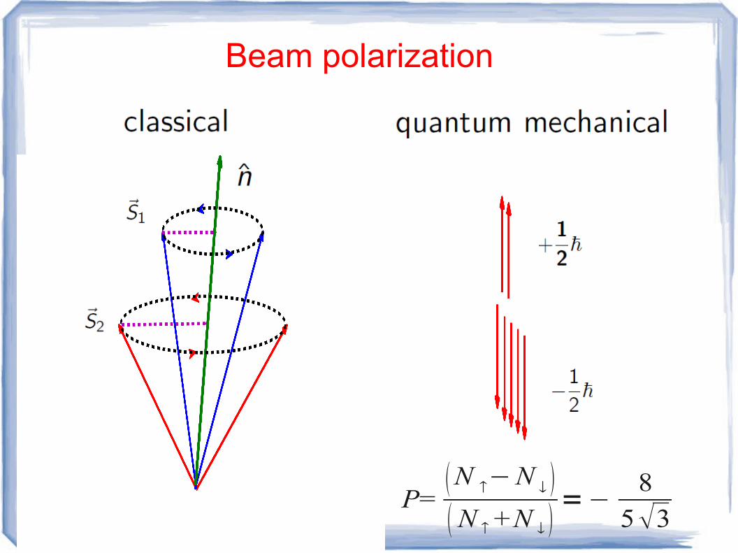
Beam polarization
P=N −N N +N
=−8
53

Electron orbital motion and spin motion
• Coordinate system Orbital
Spin
• Closed orbit orbital closed orbit
spin closed orbit
In an Ideal ring, spin closed orbit is anti-parallel
to , and orbital revolution frequency is ,
spin precession frequency is .

• Oribtial dipsersion, spin chromaticity
orbital , ,
Spin , ,
• Effects of synchrotron radiation
– Balance between radiation damping and quantum excitation emittance
– Balance between radiation spin flip and spin diffusion equilibrium polarization
• Time
– Damping time: order of ms
– Polarization build up time: minutes to hours
• Equation of motion (Classical)
– Lorentz equation
– Thomas-BMT equation
θ

Equilibrium polarization and polarization time are
D-K formula
(*) Ya.S.Derbenev, A.M.Kondratenko, Sov.Phys. JETP. 37(1973)968
(*)

Comments
1) Spin : rest frame; magnetic and electric field : Lab frame
2) Spin precession frequency is determined by the electromagnetic field seen by the electrons.
3) Direction of is the direction of spin closed orbit
4) Amplitude of and spin tune (in the ideal ring)
Thomas-BMT equation
(*) J.D. Jackson, ''Classical Electrodynamics'', Wiley, New York (1975)
(*)
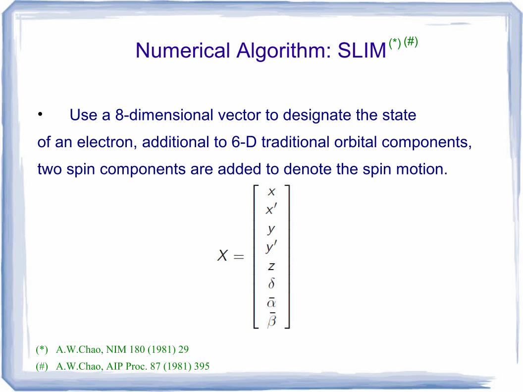
Numerical Algorithm: SLIM
• Use a 8-dimensional vector to designate the state
of an electron, additional to 6-D traditional orbital components,
two spin components are added to denote the spin motion.
(*) A.W.Chao, NIM 180 (1981) 29
(*) (#)
(#) A.W.Chao, AIP Proc. 87 (1981) 395

Characteristics of SLIM
Using eigenvectors and eigenvalues of a matrix, to
study a general, linear coupled accelerator lattice.
calculate coupled orbital motions in the 6-D phase space.
calculate coupled damping, coupled beam size
and coupled emittance;

include coupling of orbital motion on the spin motion, calculate spin closed orbit and spin chromaticity.
Calculate polarization and polarization time according to D-K formula.
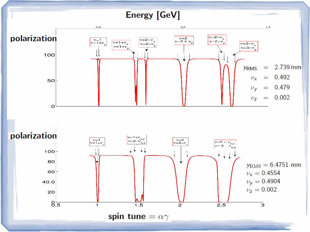
Seven sets of resonance in SLIM.

Two example applications of SLIM
• Hefei storage ring
• Duke storage ring

Layout of Hefei Storage ring
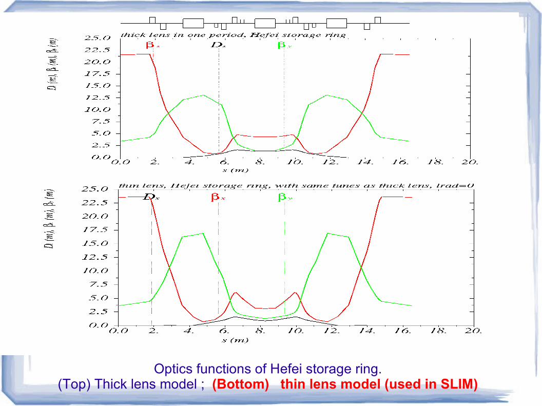
Optics functions of Hefei storage ring.
(Top) Thick lens model ; (Bottom) thin lens model (used in SLIM)

Layout of Duke accelerator;there are 2 symmetric arcs, two straight sections, south
straight section is for wigglers on the storage ring.
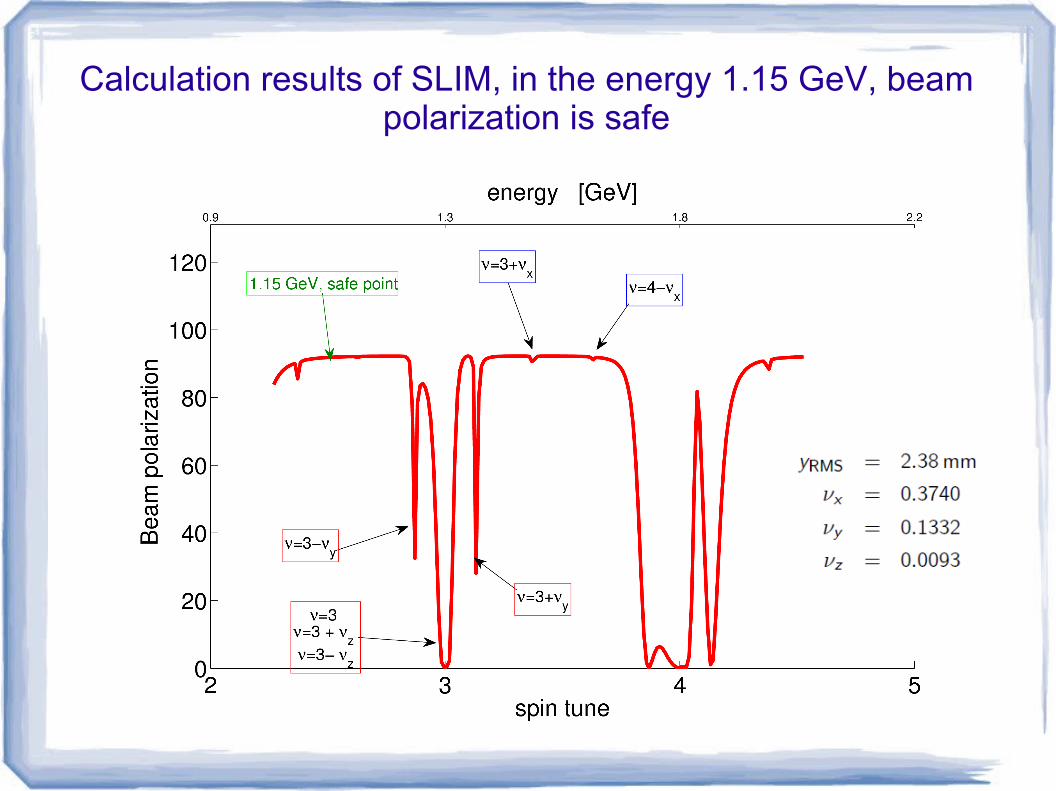
Calculation results of SLIM, in the energy 1.15 GeV, beam polarization is safe
Experiments to measure electron beam polarization

Polarimeters
Two types of polarimeters
Moller polarimeters, scattering, Jlab;
Compton polarimeters, scattering, SLAC.
• Both polarimeters are of high accuracy, but the set up are complicated and the devices are expensive.
Simple and inexpensive method ???? Even if the accuracy is not high?
(*)
(*) A.Chao, M.Tigner, Handbook of accelerator physics and engineering

Touschek beam loss
• Moller cross section polarization;
• Touschek beam loss polarization.
• For a flat, polarized electron beam,
• A is a function of momentum acceptance, etc.
A=0.15 for Duke storage ring.
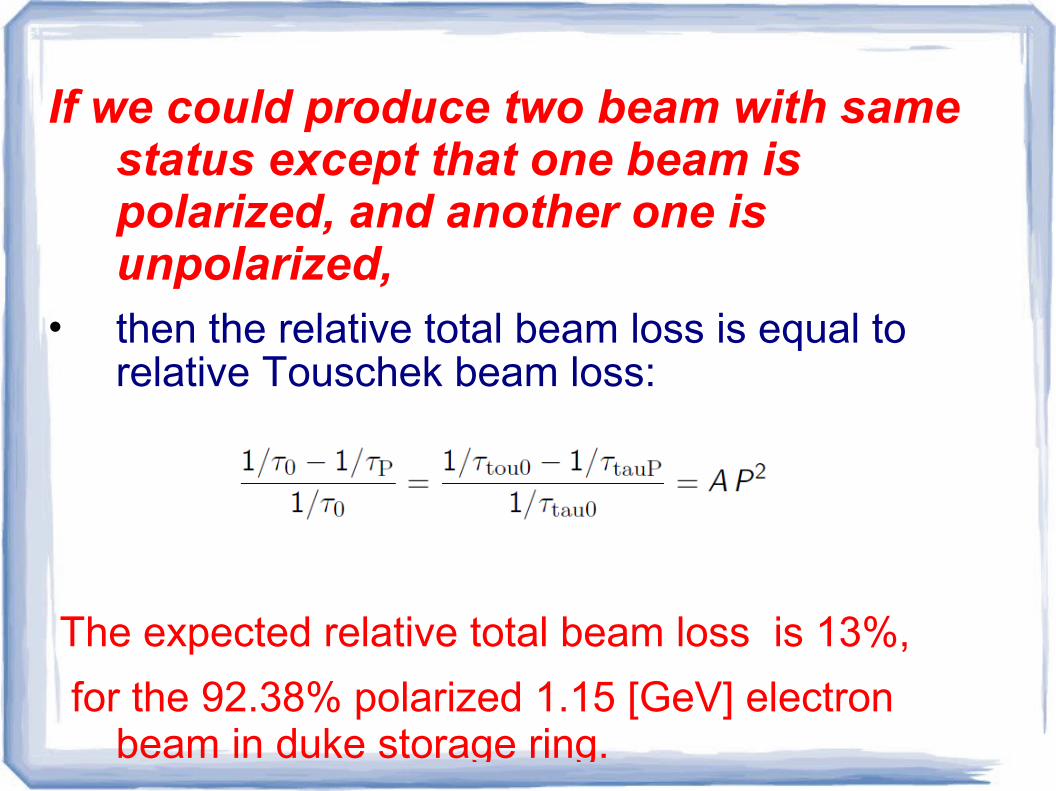
If we could produce two beam with same status except that one beam is polarized, and another one is unpolarized,
• then the relative total beam loss is equal to relative Touschek beam loss:
The expected relative total beam loss is 13%,
for the 92.38% polarized 1.15 [GeV] electron beam in duke storage ring.
Experiment feasibility study
Check whether we could produce two unpolarized beam with the beam status
• Turn on longitudinal feedback system;
• Produce two unpolarized beam, measure
their lifetime with the same current;
• Comparing the orbit, RF voltage during the two experiments;
• comparing beam size, bunch length, during the experiments.
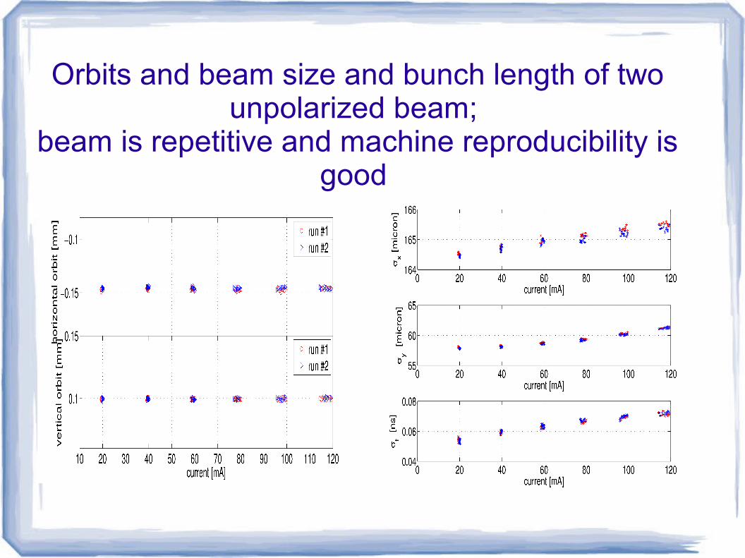
Orbits and beam size and bunch length of two unpolarized beam;
beam is repetitive and machine reproducibility is good

Lifetime comparation in two runs

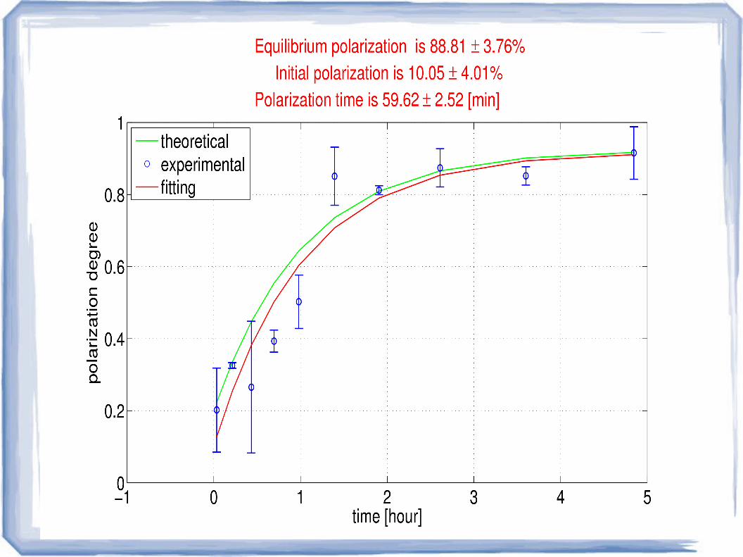
Procedures to measure polarization
Measure lifetime of an unpolarized beam.
• Measure lifetime of a polarized beam
– Use the final 120mA of unpolarized beam,
as the start current of the polarized beam, we measure lifetime of polarized beam.
– So the start beam of the polarized beam carries some initial polarization.

•Beam lifetime of the unpolarized electron beam and
polarized electron beam
Analysis of the experiment results • Maximum error of measured polarization is 18%, but
We only use the trend of measured polarization
the find polarization.
• The contribution of initial polarization to the loss rate is due to,
– we didn't measure beam lifetime at one specific time, but we measure the average lifetime in 5 minutes, some level of polarization can build up in these 5 minutes.
– The measurement error from lifetime
• The fitted polarization is not of high accuracy, but can tell us information of the equilibrium polarization, this information is sufficient for the experiment, i.e., to measure beam energy using resonant depolarization.

Resonant depolarization (RD) to measure beam energy

Based on spin tune and spin resonant condition
• Spin tune is defined as
• Add an horizontal, RF magnetic field on the beam, to drive vertical spin resonance,
• So beam energy is:
Experiment principle

• Since the known spin tune is corresponding to the nominal energy, so we need to sweep RF frequency to get the find the real beam energy.
• RF field frequency is of high accuracy, so measured beam energy is of high accuracy.

Experiment flowchart
Signal generatorstriplines
electron beamBLM
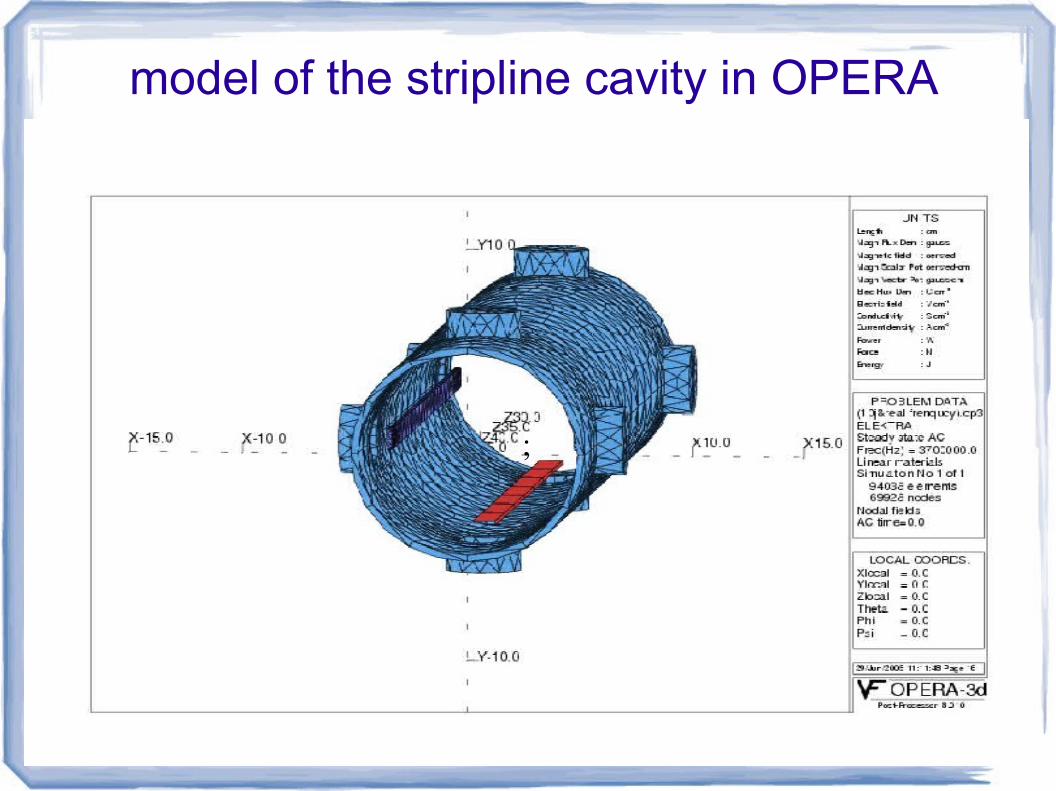
model of the stripline cavity in OPERA
;

Distribution of on axis depolarization field

Depolarization time, on axis depolarization field, input power
1.0 1.5 2.0 2.5 3.0 3.5 4.0
0
50
100
150
200
250
300
depo
lariz
atio
n tim
e /
s
integral field / Gauss. cm
dep time
0 10 20 30 40 500
20
40
60
80
100
120
140
160
180
200
depo
lariz
atio
n ti
me
/ s
input power /W
depolarization time
(*) Ya.S.Derbenev, A.M.Kondratenko, A.N.Skrinsky, Particle Accel, 9,247 (1980)
(#) P.Kuske, T.Mayer, Proceedings of EPAC96 (1996)
• Very sensitive to beam loss
• response time of beam loss monitor should be short.
• Average cost and requirement, plastic scintillation detector is a good choice.
BLM in resonant depolarization experiment

Energy spectrum of the secondary gamma photon outside the vacuum chamber
(EGSnrc)
0.0 0.5 1.0 1.5 2.0 2.5 3.0 3.5 4.0 4.5 5.0 5.5 6.00
20000
40000
60000
80000
100000
120000
co
un
t ra
tes
Energy of Photons / MeV
count rate V.S Energy of photons

Angular distribution of the secondary gamma photon outside the vacuum chamber
(EGSnrc)

Scintillation detector
Control system of the experiment
• Separate control system, from the EPICS
• Using LabView on a computer, to control the
RF scan and record the beam loss rate from the beam loss monitor.

Control panel of the RF experiment , RF scan control panel
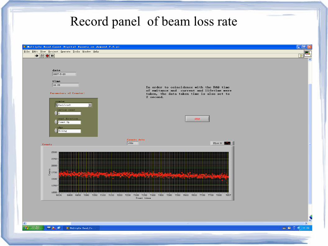
Record panel of beam loss rate

Summary
Theoretical: Study on spin dynamics
Experimental: Using a simple method to measure
electron beam polarization.
Instruments: Build an experiment set up to measure
beam energy, using the resonant depolarization method.

Thank you

Backup slides
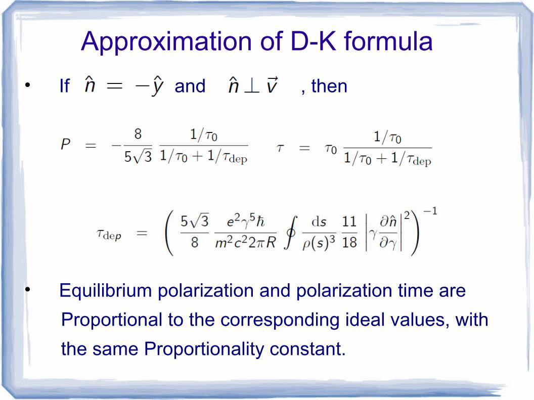
Approximation of D-K formula
• If and , then
• Equilibrium polarization and polarization time are
Proportional to the corresponding ideal values, with
the same Proportionality constant.

Touschek beam loss
• Moller cross section polarization;
• Touschek beam loss polarization.
• For a flat, polarized electron beam,
• A is a function of momentum acceptance, etc.
A=0.15 for Duke storage ring.
Can't measure Touschek loss, only can measure total beam loss.

• Electron beam Loss is mainly composed of 3 parts:
• quantum lifetime,
• vacuum lifetime,
• Touschek lifetime.
Current dependent is good, this is the key point we use in our experiment design.
Electron beam loss

Touschek lifetime of a flat, polarized beam
(*) A.A.Kresnin and L.N.Rozentsveig, Soviet Physics JETP 5 (1957) 288.(#) T.-Y. Lee, J.Choi, H.S. Kang,NIMA 554(2005) 85
(*) (#)

SLIM results of HLS

4 conditions Produce an unpolarized and a polarized beam, and with
• Instability is weak
• machine status is repeatable
• beam is reproducible
• lifetime measurement error is small
Beam loss difference between these two beam, at the same current, are only depends on polarization....

Current methods to measure beam energy
method charateristics device
Hall probeLow accuracy Simple devices,Traditional method
Hall probe
Compton backscattering
High accuracyComplicated and expensive devices, Not very popular.
Laser, high purity Ge detector, optical system,etc
Spin resonant depolarization
High accuracy to Simple and inexpensive device;Popular in recently years
Signal generator,Power amplifier,Scintillation detectors.
210
410
41010−5

Beam loss monitors (BLM)