study of the straightening process on metal profiles
TRANSCRIPT
1
STUDY OF THE STRAIGHTENING PROCESS ON METAL PROFILES THROUGH FINITE ELEMENT MODELS.
A.V. Pernía Espinoza (p)(1), J.B. Ordieres Meré (1), M. Castejón Limas (2), A.
González Marcos (2)
(1) Universidad de La Rioja, c/ Luis de Ulloa 20, 26004, Logroño, La Rioja, Spain.
(2) Universidad de León, Campus de Vegazana, s/n, 24071, León, Castilla y León, Spain.
ABSTRACT One of the most important causes of steel profiles failures is the residual stress. They are those stresses that are locked in the object without the application of any service or external loads. They influence mechanical properties of structural material and as a consequence the propagation of cracks. In this paper we study the formation of the residual stress in the straightening process through a realistic numerical simulation. This is achieved using a 3D Finite Element Model (FEM) developed with ABAQUS®.
1. INTRODUCTION Residual stresses in the material are those stresses that are locked in the object without the application of any service or external loads. They are generated first as a result of manufacturing processes, such as hot-rolling, roller-straightening, etc., then in service, when two bodies are in contact. These stresses are usually high and they can cause plastic deformation around the contact surface and modify the stress field near key zones [Webster et al., 1992].
A number of experimental techniques have been used to determine residual stresses in steel rails [Project D 156]. Destructing sectioning methods were used for the evaluation of the residual stresses. Some results are reported in [Fastenrath, 1977; Szelazek, 1992; Wineman and McClintock, 1992]. In 1993, the ERRI reported new ways to measure residual stresses [ERRI Project D 173, 1993; Webster et al., 1993] by neutron diffraction. Diffraction techniques are particularly suited to the non-destructive mapping of complex stress fields. In contrast to X-rays neutrons can penetrate the material more easily allowing the measurement of residual stresses in the interior of the material. However, it is a rather expensive (a nuclear reactor is necessary to provide the neutrons) and very time consuming method [Schleinzer G., 2000]. Hauk and Kockelmann (1994) reported measurements with several non-destructive methods. The X-ray diffraction measurements showed a very steep stress gradient from compressive stresses at the surface to tensile ones near the surface. Also high speed grilling and ring core methods were applied. The results differ and, therefore, give no clear picture of the residual stresses near the surface. From the experimental point of view, the general stress pattern appears to be clear: a C-shaped stress distribution on rails [Hodgson, 1993], while near the surface some uncertainties remain [Schleinzer G., 2000].
The advances of microelectronics and computer science have allowed to increas processing and storage computers capacity and thus the development of powerfull simulation tools. Because of the new finite-element-analysis (FEA) tools, several
448
2
theoretical investigations have been carried out. Rongbin et al. [1998] studied the principle of forming the residual stresses of steel rails in the straightening process using the ANSYS 5.4® program. They concluded that there is a tensile residual on the surface of the rail base centre. Naumann [1998] investigated a 3D FEM with ABAQUS/Explicit®. However, he did not publish residual stress result from his calculation. Schleinzer and Fischer [2001] resume and improve their results showed in [Schleinzer, 2000]. A two step 3D FEM was applied using ABAQUS/Standard® and ABAQUS/Explicit® as finite element codes. Their results are in harmony with experimental investigation.
We present the development (using ABAQUS 6.4®) of a 3D realistic model to simulate two straightening processes of train-rails and IPE sections (“beams”) from a mechanical approach. Though this model we can study residual stresses formation even inside the beams.
2. A REALISTIC 3D FINITE ELEMENT MODEL Two straightening processes will be simulated separately: one for the rail UIC 60 and the other for the IPE 100 section.
2.1 Strategies Based on the work of Schleinzer [2000] and Gerhard et al. [1998], the simulations of the straightening processes were divided into two parts, in order to achieve reasonable computing times:
• Simulation of a Global model (First step): where the movement and the bending line of the “beam” in the straightener is calculated. In contrast to Schleinzer’s [2000] work (where the rollers are moved along the beam, without rotation), in our simulation the beam is moved along the straightener by the effects of the rolls, which have a constant rotating velocity and a surface friction coefficient. All this results in a more realistic model and give us the possibility to analyze the influence of the straightening process forces on roller’s axis as it could be a relevant criteria form industrial point of view, regarding the operational life of mill components
• Simulation of a submodel (Second step): where a short part of the beam is passed through the straightener and including all effects and contacts to the rollers. The length of the small model is three times its height which is sufficient to compute the residual stress in the cross-section of a long beam in the middle of the submodel. In this second step, a more complete plasticity model is applied: Chaboche’s multiple component non-linear kinematic hardening model, to account for the cyclic plastic behaviour of the beam steel.
In this paper we present the result for the first part: The Global Model.
3. THE GLOBAL MODEL The global model was calculated with the ABAQUS/Explicit because it applies an explicit integration, suited to manage contact problems.
The main assumptions for the simulations were: • Rolls are rigid without bending.
449
3
• The camber of rails caused by slow cooling is neglected. • No residual stresses before straightening.
The element used to mesh the rail was the C3D8R (continuum solid eight node element). The rollers were generated with Analytical Rigid Surfaces. Between the rollers and the beam the basic Coulomb friction is used with a friction coefficient of 0.2. An isotropic linear plasticity model is sufficient to calculate the bending line during the straightening. Therefore, a Chaboche’s model is not applied in this global model.
3.1 Rail UIC60 3.1.1Parameters and values used in the simulation Steel Mechanical Properties The mechanical properties (at 25ºC) for the steel used in the rail UIC60 simulation are:
• Density: 7800 kg/m3. • Young’s modulus: 206 GPa • Poisson’s ratio: 0,28 • Yield stress: 440 MPa • Plastic hardening coefficient: 16000 MPa
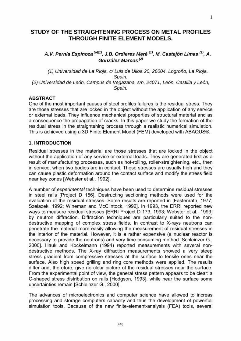
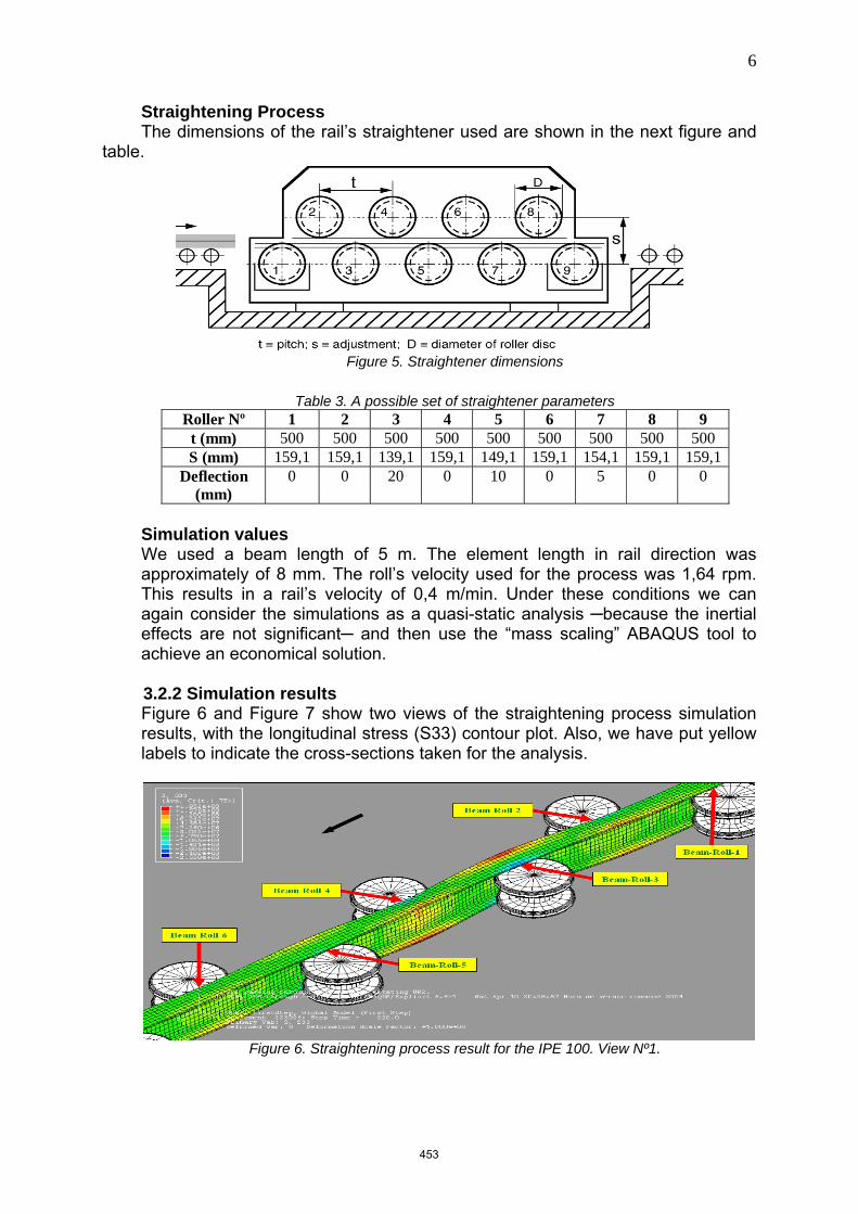
Straightening Process The dimensions of the rail’s straightener used are shown in Figure 1 and Table 1.
Figure 1. Straightener dimensions
Table 1. A possible set of straightener parameters
Roller Nº 1 2 3 4 5 6 7 8 9 Diameter (mm) 845
Pitch (mm) 1024,5 685,5 685,5 685,5 685,5 685,5 685,5 685,5 1024,5Deflection (mm) 0 0 9,77 0 6,65 0 2,83 0 0
Simulation values We used a rail length of 12 m. The element length in rail direction was approximately of 30 mm. The roll’s velocity used for the process was 0,38 rpm, which is a typical straightener velocity. This results in a rail’s velocity of 1m/min. Under these conditions we can consider the simulations as a quasi-static analysis ─because the inertial effects are not significant─ and then use the “mass scaling” ABAQUS tool to achieve an economical solution.
450
4
3.1.2 Simulation results The results of the straightening process for the rail UIC 60 are now presented. All values correspond to the final simulation time (T).
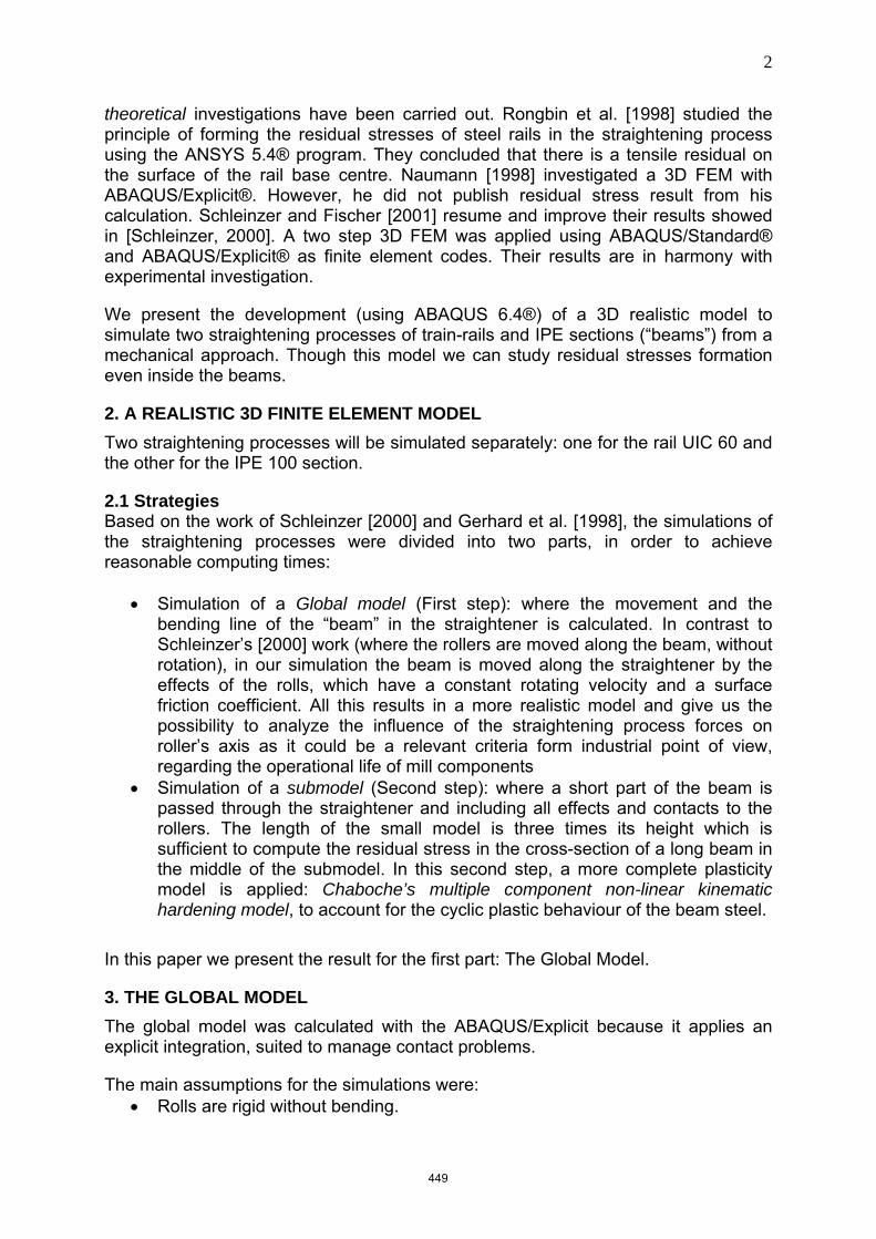
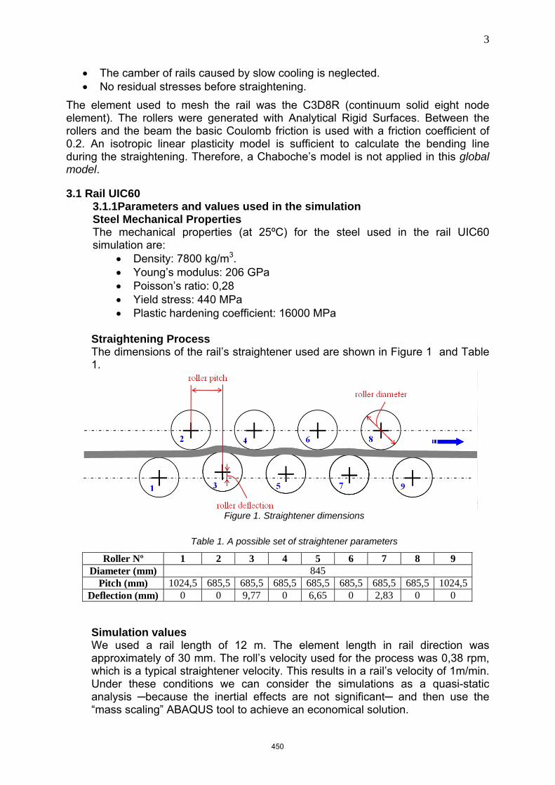
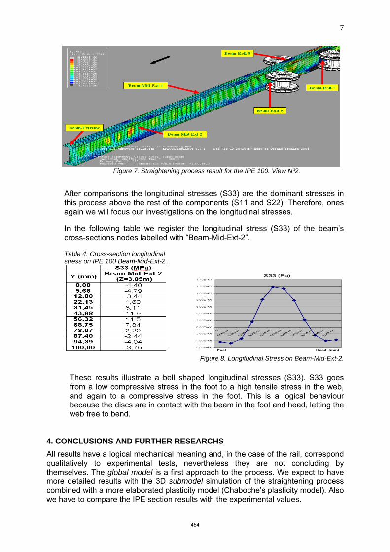
Figure 2 and Figure 3 show two views of the straightening process simulation with the longitudinal stress (S33) contour plot. Also, we have put yellow labels to indicate the cross-sections positions taken for the analysis.
Figure 2. Straightening process result for the Rail UIC 60. View Nº1.
Figure 3. Straightening process result for Rail UIC 60. View Nº2.
Due to the lack of space available in this paper we just present the residual stresses (S33), of the rail’s cross-sections nodes, in the section labelled as “Rail-Mid-Ext-2”.
The longitudinal stresses (S33) are the dominant stresses in this process if we compare them to the rest of the three axial stress components (S11 and S22). Hence, we will focus our investigations on the formation of the longitudinal stresses. In the following table we register the longitudinal stress (S33) of the rail’s cross-sections nodes labelled with “Rail-Mid-Ext-2”.
451
5
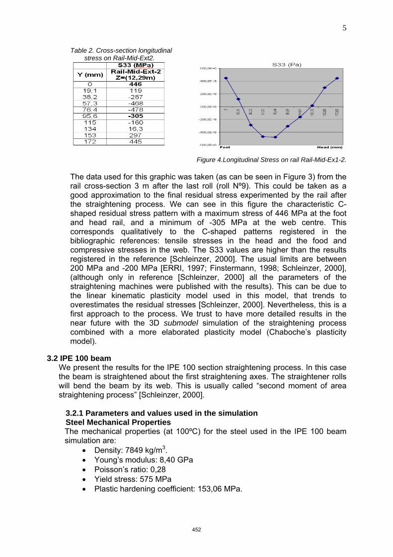
Table 2. Cross-section longitudinal stress on Rail-Mid-Ext2.
Figure 4.Longitudinal Stress on rail Rail-Mid-Ex1-2.
The data used for this graphic was taken (as can be seen in Figure 3) from the rail cross-section 3 m after the last roll (roll Nº9). This could be taken as a good approximation to the final residual stress experimented by the rail after the straightening process. We can see in this figure the characteristic C-shaped residual stress pattern with a maximum stress of 446 MPa at the foot and head rail, and a minimum of -305 MPa at the web centre. This corresponds qualitatively to the C-shaped patterns registered in the bibliographic references: tensile stresses in the head and the food and compressive stresses in the web. The S33 values are higher than the results registered in the reference [Schleinzer, 2000]. The usual limits are between 200 MPa and -200 MPa [ERRI, 1997; Finstermann, 1998; Schleinzer, 2000], (although only in reference [Schleinzer, 2000] all the parameters of the straightening machines were published with the results). This can be due to the linear kinematic plasticity model used in this model, that trends to overestimates the residual stresses [Schleinzer, 2000]. Nevertheless, this is a first approach to the process. We trust to have more detailed results in the near future with the 3D submodel simulation of the straightening process combined with a more elaborated plasticity model (Chaboche’s plasticity model).
3.2 IPE 100 beam We present the results for the IPE 100 section straightening process. In this case the beam is straightened about the first straightening axes. The straightener rolls will bend the beam by its web. This is usually called “second moment of area straightening process” [Schleinzer, 2000].
3.2.1 Parameters and values used in the simulation Steel Mechanical Properties The mechanical properties (at 100ºC) for the steel used in the IPE 100 beam simulation are:
• Density: 7849 kg/m3. • Young’s modulus: 8,40 GPa • Poisson’s ratio: 0,28 • Yield stress: 575 MPa • Plastic hardening coefficient: 153,06 MPa.
452
6
Straightening Process The dimensions of the rail’s straightener used are shown in the next figure and
table.
Figure 5. Straightener dimensions
Table 3. A possible set of straightener parameters
Roller Nº 1 2 3 4 5 6 7 8 9 t (mm) 500 500 500 500 500 500 500 500 500 S (mm) 159,1 159,1 139,1 159,1 149,1 159,1 154,1 159,1 159,1
Deflection (mm)
0 0 20 0 10 0 5 0 0
Simulation values We used a beam length of 5 m. The element length in rail direction was approximately of 8 mm. The roll’s velocity used for the process was 1,64 rpm. This results in a rail’s velocity of 0,4 m/min. Under these conditions we can again consider the simulations as a quasi-static analysis ─because the inertial effects are not significant─ and then use the “mass scaling” ABAQUS tool to achieve an economical solution. 3.2.2 Simulation results Figure 6 and Figure 7 show two views of the straightening process simulation results, with the longitudinal stress (S33) contour plot. Also, we have put yellow labels to indicate the cross-sections taken for the analysis.
Figure 6. Straightening process result for the IPE 100. View Nº1.
453
7
Figure 7. Straightening process result for the IPE 100. View Nº2.
After comparisons the longitudinal stresses (S33) are the dominant stresses in this process above the rest of the components (S11 and S22). Therefore, ones again we will focus our investigations on the longitudinal stresses.
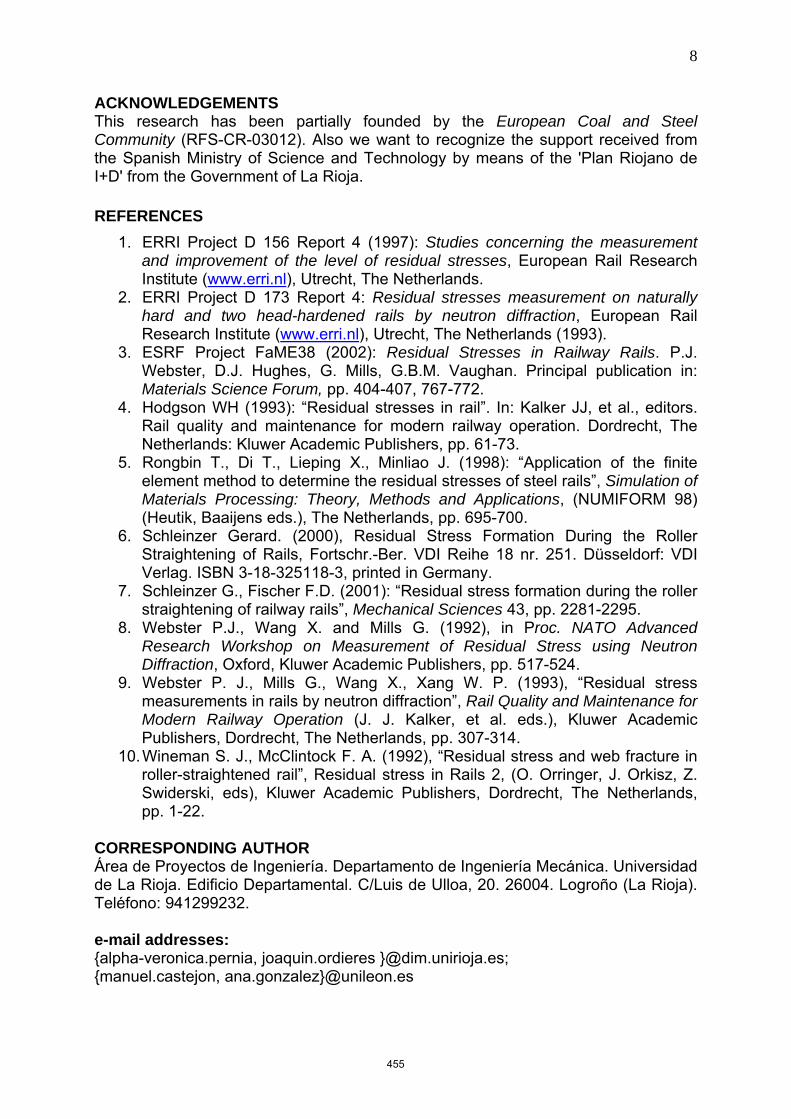
In the following table we register the longitudinal stress (S33) of the beam’s cross-sections nodes labelled with “Beam-Mid-Ext-2”.
Table 4. Cross-section longitudinal stress on IPE 100 Beam-Mid-Ext-2.
Figure 8. Longitudinal Stress on Beam-Mid-Ext-2.
These results illustrate a bell shaped longitudinal stresses (S33). S33 goes from a low compressive stress in the foot to a high tensile stress in the web, and again to a compressive stress in the foot. This is a logical behaviour because the discs are in contact with the beam in the foot and head, letting the web free to bend.
4. CONCLUSIONS AND FURTHER RESEARCHS All results have a logical mechanical meaning and, in the case of the rail, correspond qualitatively to experimental tests, nevertheless they are not concluding by themselves. The global model is a first approach to the process. We expect to have more detailed results with the 3D submodel simulation of the straightening process combined with a more elaborated plasticity model (Chaboche’s plasticity model). Also we have to compare the IPE section results with the experimental values.
454
8
ACKNOWLEDGEMENTS This research has been partially founded by the European Coal and Steel Community (RFS-CR-03012). Also we want to recognize the support received from the Spanish Ministry of Science and Technology by means of the 'Plan Riojano de I+D' from the Government of La Rioja.
REFERENCES
1. ERRI Project D 156 Report 4 (1997): Studies concerning the measurement and improvement of the level of residual stresses, European Rail Research Institute (www.erri.nl), Utrecht, The Netherlands.
2. ERRI Project D 173 Report 4: Residual stresses measurement on naturally hard and two head-hardened rails by neutron diffraction, European Rail Research Institute (www.erri.nl), Utrecht, The Netherlands (1993).
3. ESRF Project FaME38 (2002): Residual Stresses in Railway Rails. P.J. Webster, D.J. Hughes, G. Mills, G.B.M. Vaughan. Principal publication in: Materials Science Forum, pp. 404-407, 767-772.
4. Hodgson WH (1993): “Residual stresses in rail”. In: Kalker JJ, et al., editors. Rail quality and maintenance for modern railway operation. Dordrecht, The Netherlands: Kluwer Academic Publishers, pp. 61-73.
5. Rongbin T., Di T., Lieping X., Minliao J. (1998): “Application of the finite element method to determine the residual stresses of steel rails”, Simulation of Materials Processing: Theory, Methods and Applications, (NUMIFORM 98) (Heutik, Baaijens eds.), The Netherlands, pp. 695-700.
6. Schleinzer Gerard. (2000), Residual Stress Formation During the Roller Straightening of Rails, Fortschr.-Ber. VDI Reihe 18 nr. 251. Düsseldorf: VDI Verlag. ISBN 3-18-325118-3, printed in Germany.
7. Schleinzer G., Fischer F.D. (2001): “Residual stress formation during the roller straightening of railway rails”, Mechanical Sciences 43, pp. 2281-2295.
8. Webster P.J., Wang X. and Mills G. (1992), in Proc. NATO Advanced Research Workshop on Measurement of Residual Stress using Neutron Diffraction, Oxford, Kluwer Academic Publishers, pp. 517-524.
9. Webster P. J., Mills G., Wang X., Xang W. P. (1993), “Residual stress measurements in rails by neutron diffraction”, Rail Quality and Maintenance for Modern Railway Operation (J. J. Kalker, et al. eds.), Kluwer Academic Publishers, Dordrecht, The Netherlands, pp. 307-314.
10. Wineman S. J., McClintock F. A. (1992), “Residual stress and web fracture in roller-straightened rail”, Residual stress in Rails 2, (O. Orringer, J. Orkisz, Z. Swiderski, eds), Kluwer Academic Publishers, Dordrecht, The Netherlands, pp. 1-22.
CORRESPONDING AUTHOR Área de Proyectos de Ingeniería. Departamento de Ingeniería Mecánica. Universidad de La Rioja. Edificio Departamental. C/Luis de Ulloa, 20. 26004. Logroño (La Rioja). Teléfono: 941299232. e-mail addresses: {alpha-veronica.pernia, joaquin.ordieres }@dim.unirioja.es; {manuel.castejon, ana.gonzalez}@unileon.es
455