study of reliable data communication in wireless sensor
TRANSCRIPT
Louisiana State UniversityLSU Digital Commons
LSU Master's Theses Graduate School
2006
Study of Reliable Data Communication in WirelessSensor NetworksRavilochan G. ShamannaLouisiana State University and Agricultural and Mechanical College, [email protected]
Follow this and additional works at: https://digitalcommons.lsu.edu/gradschool_theses
Part of the Computer Sciences Commons
This Thesis is brought to you for free and open access by the Graduate School at LSU Digital Commons. It has been accepted for inclusion in LSUMaster's Theses by an authorized graduate school editor of LSU Digital Commons. For more information, please contact [email protected].
Recommended CitationShamanna, Ravilochan G., "Study of Reliable Data Communication in Wireless Sensor Networks" (2006). LSU Master's Theses. 873.https://digitalcommons.lsu.edu/gradschool_theses/873

STUDY OF RELIABLE DATA COMMUNICATION IN WIRELESS SENSOR
NETWORKS
A Thesis
Submitted to the Graduate Faculty of the
Louisiana State University and
Agricultural and Mechanical College
in partial fulfillment of the
requirements for the degree of
Master of Science in Systems Science
in
The Department of Computer Science
By
Ravilochan G. Shamanna
B.E., Visvesvaraya Technological University, Belgaum, India, 2002
December 2006

ii
Acknowledgements
I would like to extend my sincere gratitude to my major professor Dr. Rajgopal
Kannan for his guidance and encouragement during the course of this thesis work. I am
extremely grateful to my committee member Dr. S. Sitharama Iyengar for his constant
encouragement, support and guidance during my graduate studies at LSU.
I would like to further extend my sincere gratitude to my committee member
Dr. Bijaya B. Karki for his guidance and invaluable suggestions.
I am extremely grateful to the Department of Computer Science, for providing me with
the resources needed for completing my thesis research.

iii
Table of Contents
Acknowledgments …………………………………………………………………... ii
Abstract ………………………………………………………………………………. v
Chapter
1. Introduction ……………………………………………………………………… 1
1.1 Overview of Sensor Networks ……………………………………………….. 1
1.2 Motivation ……………………………………………………………………. 2
1.3 Objectives of the Thesis …………………………………………………....... 2
1.4 Contributions of This Thesis ………………………………………………… 3
1.5 Thesis Organization ………………………………………………………….. 3
2. Reliability in Wireless Sensor Networks ……………………………………….. 4
2.1 Need for Reliable Data Communication ……………………………………... 4
2.2 Comparisons with TCP for Internet …………………………………………. 4
2.3 Literature Survey …………………………………………………………….. 5
2.3.1 Single Packet Delivery ……………………………………………….. 6
2.3.2 Packet Block Delivery ……………………………………………….. 11
2.3.3 Packet Stream Delivery …………………………………………......... 17
2.3.4 Reliable Multi-hop Routing …………………………………………… 19
3. Cross-Layer Optimizations for Single Packet Reliable Data Transfer ……….. 23
3.1 Need for Cross-Layer Approach ……………………………………………… 23
3.2 Experimental Test Bed ……………………………………………………….. 24
3.3 MAC Layer Protocol ………………………………………………………..... 26
3.3.1 Evaluating Reliability in One Hop Unicast Message Delivery ……...... 26
3.4 Network Layer – NACK Based Route Rediscovery ………………………..... 28
4. Implementation on TinyOS ….…………………………………………………. 32 4.1 Application Configuration …………………………………………………... 33
4.2 Message Structure and Types ……………………………………………….. 34
4.3 Event Handling ……………………………………………………………… 35
4.4 Neighborhood Table Management ………………………………………….. 38
4.5 Data Message Buffer Management …………………………………………. 39
5. Evaluation and Results …………………………………………………………. 41 5.1 Simulation Setup …………………………………………………………….. 41
5.2 Message Reception at the Sink for Varying Network Sizes ………………… 42
5.3 Message Reception at the Sink for Varying percentage of Link Failures ……. 43
5.4 Message Reception at the Sink for Varying Network Traffic ……………….. 44
6. Conclusion and Future Work …………………………………………….. ….. 48

iv
6.1 Conclusion ……………………………………………………………........... 48
6.2 Future Work. ……………………………………………………………….. 48
Bibliography …………………………………………………………………............ 49
Vita ………..…………………………………………………………………............. 52

v
Abstract
A distributed wireless sensor network consists of numerous tiny autonomous sensing
nodes deployed across a wide geographical area. These sensor nodes self organize and
establish radio communication links with the neighboring nodes to form multi-hop
routing paths to the central base station. The dynamic and lossy nature of wireless
communication poses several challenges in reliable transfer of data from the sensor nodes
to the sink.
There are several applications of sensor networks wherein the data collected by the
sensors in the network are critical and hence have to be reliably transported to the sink.
An example of such an application is sensors with RFID readers mounted on them to read
tag information from the objects in a factory warehouse. Here, the tag information
recorded by the RFID reader is a critical piece of information which may not be available
at a later point of time and hence has to be reliably transported to the sink. We study the
various issues and analyze the design choices proposed in literature in addressing the
challenge of sensors-to-sink reliable data communication in such applications. A cross-
layer based protocol with MAC layer retransmissions and NACK (Negative
Acknowledgment) based rerouting of data packets is developed to overcome link failures
and provide reliability. The protocol is implemented on TinyOS and the performance of
NACK based rerouting protocol in terms of percentage successful message reception is
compared with NACK based retransmission protocol by running simulations on
TOSSIM. The NACK based rerouting protocol provides greater reliability under different
metrics like varying network size, network traffic and percentage of failed links in the
network.

1
Chapter 1
Introduction
1.1 Overview of Sensor Networks
A sensor network consists of several sensing devices deployed in a given geographical
area for collaboratively gathering/sensing specific information in the environment for
later analysis at a central base station. The sensor nodes self organize after deployment to
establish radio communication paths to the sink. The sensing devices are low power
devices consisting of a microcontroller for information processing, a microchip and
antenna for radio communication and a sensor for sensing environmental parameters like
temperature, humidity, light intensity etc. Some of the applications of sensor networks
are –
• Military applications like target tracking where numerous tiny sensors are
deployed in a geographical terrain to track the movement of enemy vehicles.
• Habitat monitoring applications in which a sensor network is deployed in the
habitat of a particular animal or bird under consideration to periodically gather
environmental parameters like temperature, humidity and light intensity. The data
collected can be later used to make analysis about the favorable environmental
conditions for optimal development and growth of the animal/bird.
• Safety applications like fire and smoke detection where in a network of sensors
capable of detecting smoke is deployed in a huge building to track the source and
direction in which the fire is expanding in the building which has caught fire. This
can assist in better rescue and recovery operations.

2
1.2 Motivation
Current research in the areas of wireless communications, micro-electromechanical
systems and low power design is progressively leading to the development of cost
effective, energy efficient, multifunctional sensor nodes. Sensing, communication,
processing and battery units are the primary components of a sensor node. Individual
sensors have the capacity to detect events occurring in their area of deployment.
Reliable data transport is an important facet of dependability and quality of service in
several applications of wireless sensor networks. Different applications have different
reliability requirements, for example an application to collect environmental parameters
like temperature, humidity etc periodically can ignore an occasional loss of a value from
a particular sensor but for an application in which the data collected by every sensor is a
critical piece of information then end-to-end reliability has to be guaranteed for every
individual packet.
An example for an application that requires guaranteed end-to-end reliability is an
integration of Radio Frequency Identification (RFID) and wireless sensor network for
automated inventory management and tracking [24]. In this application setup the sensor
devices called motes [25] are attached with RFID readers to record RFID tag information
on the objects. These sensor motes have a critical piece of information to be sent to the
sink. Therefore reliable sensor-to-sink communication has to be guaranteed for such
applications. This is the main motivation behind studying the various issues and
strategies of reliable communication in this thesis.
1.3 Objectives of the Thesis
The primary objectives of this thesis are the following –

3
• To study and analyze the problem of reliable data communication in wireless
sensor networks. To study the advantages and drawbacks of the various schemes
proposed in literature for reliable data communication.
• To propose and evaluate a cross layer based approach for enabling guaranteed
reliable sensor-to-sink data communication.
1.4 Contributions of This Thesis
The main contributions of this thesis work are as follows
• We develop insight into the reliability requirements for applications of sensor
networks where in the data collected by the individual sensors is critical.
• We study and analyze the various reliability mechanisms proposed in the
literature for single packet delivery of aggregated data or critical data, packet
block delivery from the sink to the sensors and packet stream delivery when the
sensors are delivering time series data.
• We propose a cross-layer based scheme for guaranteeing end-to-end reliable
transfer of critical data from the sensors to the sink.
1.5 Thesis Organization
This thesis is organized into four main chapters. In chapter 2 we discuss the need for
reliability mechanisms for sensor networks and the applicability of TCP like mechanism
for guaranteed end-to-end reliable data transfer. In chapter 3 we develop a cross-layer
based mechanism for end-to-end reliable transfer of single packet data. In chapter 4 the
implementation aspects of the protocol is described. In chapter 5 we evaluate the protocol
by running simulations on TOSSIM simulator. In chapter 6 we draw conclusions and list
possible areas of future work.

4
Chapter 2
Reliability in Wireless Sensor Networks
2.1 Need for Reliable Data Communication
The design of sensor network is application specific and different applications have
different reliability requirements. Applications like habitat monitoring [31], periodic
collection of environmental parameters like temperature, humidity etc can tolerate a loss
in data packets but in event detection sensor networks the critical information pertaining
to the event has to be reliably transported to the central station or sink. Examples of event
detection applications include target detection and tracking and inventory management
using sensors with RFID readers mounted on them [24]. Applications like these in which
the sensors have a critical piece of information to be transported to the sink are the central
focus of this thesis.
The causes for data communication in sensor networks to be unreliable are –
• The wireless links can be unreliable which leads to packet losses.
• Congestion in the network leads to packet losses as the packets are dropped by
intermediate/routing nodes in the routing paths.
• Channel bit errors during wireless data transmissions.
2.2 Comparisons with TCP for Internet
The transmission control protocol (TCP) is a transport layer protocol that provides end-
to-end reliability for the internet. A TCP like transport layer protocol is not suitable for
sensor network due to the following reasons

5
Address centric routing - TCP uses unique IP address for the end systems whereas
certain applications of sensor networks use data-centric routing. For these applications a
TCP protocol will not be suitable.
Header overhead – TCP uses a large header to include information regarding sequence
number, version, options etc which is an overhead for a resource constrained sensor
network.
Energy inefficiency – TCP uses end-to-end acknowledgement and retransmission
scheme for guaranteeing reliable data transfer. Such mechanisms for guaranteeing end-to-
end reliability are energy inefficient for sensor networks.
Response to packet losses - TCP interprets the cause for packet losses to be network
congestion where as in wireless networks the packet errors are often due to bit-errors. So
a TCP for wireless sensor network will misinterpret the packet loss as congestion and
lower the sending rate even though the network is not congested.
2.3 Literature Survey
Data communication in sensor networks can happen in the following ways:
• Single packet sensors-to-sink data delivery: In this communication scenario the
sensors deliver critical packets for example some highly aggregated data or an
important item tag information in inventory tracking applications [24].
• Block of packets delivery: In applications where the sink disseminates new code
or new queries into the network for retasking [1], large blocks of packets will
need to be transported from the sink to the sensors.
• Stream of packets: Applications in which the sensor nodes periodically report data
to the sink is the primary example of stream of packets communication.

6
2.3.1 Single Packet Delivery
Single packet delivery is important when the sensor nodes send a critical piece of
information to the sink node. The critical piece of information could be an
aggregation of data collected over a period of time or detection of an important
event. Reliable single packet delivery can be achieved with the following
approaches –
A. Single path delivery with MAC – layer retransmissions
In order to provide reliability with MAC – layer retransmissions the following
issues needs to be resolved –
• Who detects losses and what are the indicators used?
• Who requests retransmissions?
• Who actually carries out these retransmissions?
In single packet delivery using MAC – layer retransmissions the transmitting
node has to detect losses by using timers and has to carry out the retransmissions.
The receiver will notify successful reception by sending acknowledgments.
Block or stream delivery has more flexibility as it is possible to let the receiver
detect losses for example, by checking for holes in the sequence number space
and request retransmission of missing packets by using negative acknowledgment
(NACK) packets. If additionally NACKs are understood as carrying implicit
acknowledgments then there is no necessity to send positive acknowledgments for
every packet, thus saving lots of energy.
MAC - layer retransmissions: When a node in the routing path forwards the data
packet, it expects to receive a MAC-layer acknowledgment. For setting timers
single-hop propagation delays and packet processing times have to be considered.

7
Typically, the transmitter makes a bounded number of trials to successfully
forward the packet and drops it after this number has been exhausted.
A CSMA (Carrier Sense Multiple Access) based adaptive rate control scheme for
media access in sensor networks: A.Woo et. al in [13] propose a Media Access
control scheme for sensor networks by studying the unique application behavior
and tight constraints in computation power, storage, energy resources and radio
technology. The protocol design is as follows –
• Listening Mechanism – Carrier Sense Multiple Access (CSMA) and
collision detection schemes found in Ethernet are examples of listening
mechanisms. Listening is effective when all nodes can hear each other,
(i.e. without hidden nodes). Though listening is simple, it does come with
an energy cost, because the radio must be on to listen. To conserve energy,
it is important to shorten the length of carrier sensing.
The highly synchronized nature of the traffic imposes new criteria for
CSMA. Since there are no mechanisms for detecting collisions, nodes that
happen to send at the same time will corrupt each other. If the traffic
pattern is independent, this situation is not likely to repeat. However,
detecting of common events by nodes will synchronize data transfers from
these nodes which can lead corruption of all data. The solution is to use
random delay for transmission to unsynchronize the nodes.
• Backoff Mechanism
Random backoff is used to reduce contention. The idea of backoff is to
restrain a node from accessing the channel for a period of time and
hopefully the channel will be free after the backoff period.

8
• Rate Control Mechanism
The tension between originating traffic and route-thru traffic has a direct
impact in achieving the fairness objective. The authors propose an implicit
mechanism which passively adapts the rate of transmission of both
original and route-thru traffic without the use of any MAC control packets.
The adaptive rate control idea is simple and is best explained with an
analogy of metering traffic onto a freeway where the route-thru traffic is
like traffic on the freeway and each node originating data is like cars
trying to enter. Periodically a node attempts to inject a packet. If the
packet is successfully injected it becomes part of the route-thru traffic. As
it is routed by the node’s parent, it signals that the road still has capacity
for more traffic and thus, the node can increase its transmission rate.
However if the injection of the packet wasn’t successful, it signals that the
road is jammed and the node decreases its rate of originating data and
backoff to achieve a phase change effect.
As we can see this CSMA mechanism provides an effective media access control
without the use of explicit control packets. The authors show using simulations
that the proposed mechanism is effective in achieving fairness while maintaining
good aggregate bandwidth with reasonable energy efficiency.
The Hidden Node problem
Figure 2.1 illustrates the hidden node problem. Suppose that node A wants to
transmit to node B located at a distance x from A. By only sensing the medium,
node A will not be able to hear the transmissions by any node (C) in the dashed
area denoted by A(x), and will start transmitting, leading to collisions at node B.

9
This is the well known hidden terminal problem, where the hidden nodes are
located in the area A(x).
Figure 2.1 Hidden Node Problem
S-MAC Protocol: W.Ye et. al in [14] propose S-MAC a medium access control
protocol for wireless sensor networks which has the following features –
• The authors propose a low-duty-cycle scheme for multi-hop networks that
reduces energy consumption due to idle listening. Idle listening refers to
the nodes listening to the wireless channel even when it is not expecting
any messages. Every node maintains a schedule for sleep and listen cycles.
• They propose a RTS/CTS (Request to send, Clear to send) mechanism for
collision avoidance. This mechanism solves the hidden node problem by
exchanging the control information packets – RTS and CTS before
actually sending the data packet. This increases the reliability of packet
delivery for large data message sizes (100 bytes – 200 bytes) when
compared to the CSMA protocol [15]. However for smaller data sizes the
A . . B
. C
Transmission range of A
Hidden terminals for
Node pair A/B – A(x)

10
exchange of control packets – RTS and CTS – is an overhead in terms of
energy consumption and latency.
B. Single path delivery with end-to-end retransmissions
In this the source node needs to buffer the packet until an acknowledgement
from the sink node arrives. The number of retransmissions that the node does
is typically bounded. However setting timers is harder in this case as
reasonable guesses would need knowledge on the number of hops, the per-hop
delay and the effect of current cross-traffic. Another drawback in using end-
to-end retransmissions is the overhead of retransmitting the packets along the
entire routing path even when the packet loss has occurred close to the
destination. The scheme proposed in Chapter 3 addresses these specific
drawbacks.
The HHR approach (Hop-by-Hop Reliability) described in [16] relies on
sending multiple copies of the same packet which are unicast by each node
back to back to the next upstream node. The required number of copies is
determined from a locally estimated packet error rate, the desired packet level
probability and the hop-distance to the sink. Alternatively, packets are
repeated until a local acknowledgment has been received (HHRA). These
schemes are sub-optimal since multiple copies are simply wasted when copies
are transmitted during good channel periods i.e., when the bit-error rate is low,
when a single or a few packets would likely suffice.
C. Using multiple paths
One of the approaches in using multiple paths is to set them up in advance
and declare one of them as the default route. Once problems occur, another

11
route is used [17] or the route is repaired locally by a rerouting scheme [18].
However in either case extra route maintenance is required which does not
necessarily pay off in single delivery applications.
Other approaches send not only a single packet over one of the paths but
transmit multiple packets over multiple paths in parallel. In the ReInForM
scheme [19], multiple copies of the same packet are transmitted over
randomly chosen routes. Specifically, it is assumed that a packet is destined to
a sink node and that each node knows its hop distance to the sink as well as
the hop distances of all its immediate neighbors. Packet duplication can occur
at every intermediate node, not only at the source node. An intermediate node
has to decide two things: the number of copies to create and the upstream
nodes to which the packet is actually forwarded. With respect to the latter
choice, ReInForM prefers nodes which are closer to the sink but otherwise the
choice is random. This distributes the load over many nodes and avoids quick
depletion of nodes along a “good” route. The number of duplicates is
determined from the locally estimated error rate, the hop distance to the sink
and the target delivery probability.
2.3.2 Packet Block Delivery
Block transfers are needed when large amounts of data (e.g., code updates)
have to be transported. One important feature of such block transfers is that
NACKs (Negative acknowledgments) can be used. This potentially reduces the
number of acknowledgment packets.
A NACK is regarded as a retransmission request issued by the receiver. When
an intermediate node caches the segments, it can serve such a request as well as

12
the original source node could but with the benefit that the NACK and the
following retransmitted segment do not need to travel the whole distance between
source and sink node. Such a node is also called a recovery server [20] [21]. In an
extreme case, all nodes in the network could spend buffer for caching.
Let us discuss some of the schemes incorporating the above ideas.
A. PSFQ: Pump Slowly, Fetch Quickly
The PSFQ protocol presented in [1] is a transport level protocol designed to
deliver a number of segments from a single source node to a subset of receiver
nodes or even to all nodes within a sensor network. It provides guaranteed
delivery, eg., for code updates.
The protocol consists of three basic primitives: a pump operation, a fetch
operation and a report operation. In the pump operation, the sink node
transmits all the segments making up the block one by one, using MAC-layer
broadcasts. The time T min between the different segments is comparably large
and hence the pumping operation is considered slow pumping. Each segment
is equipped with a sequence number. All other nodes behave as follows:
• When a node A receives a new segment not yet seen, it stores it in an
internal cache. When the segment has already been received before,
the new segment is simply dropped.
• When a new segment is received in-sequence, node A waits for some
random time and forwards it further. However, forwarding is
suppressed when A finds that four or more of its neighbors have
already forwarded the same segment, since the expected additional
coverage achieved by A forwarding the segment tends to be small.

13
• When a packet is received out-of sequence, it is also stored, but instead
of forwarding it, the node requests immediate retransmission of the
missing segments from any upstream neighbor using a NACK
message indicating the missing segments. This is the process of
quickly recovering from the error in the packet sequence. As soon as
the node receives the missing segments, it starts forwarding the
segments in-sequence in the pumping mode, i.e. with long delays in
between.
The decision to forward packets only in-sequence has the advantage that
loss events do not propagate: Suppose that node A pumps packets x 1 , x 2 ,
x 3 …, x n . Node A’s downstream neighbor B has received and forwarded
packet x i and receives the packet x 2+i afterwards. Node B triggers a fetch
operation. If B were to forward x 2+i further to some downstream (w.r.t B)
node C, C would also trigger a fetch operation which is useless and a
waste of energy.
The fetch operation corresponds to a NACK or a retransmission
request and is triggered by missing sequence number. When segments
from the end of the block are missing, there is no higher sequence number
and this method of detecting packet losses fails. To attack this problem, a
node A proactively triggers the fetch operation by sending the NACK
packet. If the upstream neighbors do not posses the packets, they forward
the NACK packet further upstream until it eventually reaches the node
having the missing segments.

14
The NACK packets themselves are broadcasted and any upstream
neighbor having some of the missing segments is invited to respond. To
avoid collisions among these packets, the nodes use random delays before
sending the answer.
The report operation is requested from the sink node. The most far-away
nodes from the sink issue report packets indicating their own address and
the received/missing segments. This way the sink can judge the progress
of the code block dissemination.
B. GARUDA
The scheme developed in the GARUDA project [20] addresses a similar
problem as PSFQ, namely the reliable transfer of block data from the sink to
all sensors or a significant part of the network. GARUDA uses a NACK-
based scheme and additionally takes great care that the first packet in the
block is reliably delivered to all sensors. This solves the problem of NACK-
based schemes that a receiver needs to receive at least one packet from the
block to detect losses of further packets at all.
GARUDA constructs an approximation to the minimum dominating set of
the sensor network topology and the members of this set (called core
members) act as recovery servers for downstream core members and
neighboring non-core members. Only those nodes are candidates for the core
that have a hop distance to the sink which is an integral multiple of three. A
candidate core member refrains from becoming a core member when there are
enough core members in its neighborhood. On the other hand, non-core
members having no core member in their range can request a candidate core

15
member to really become a core member. All core members know at least one
upstream (i.e. closer to the sink) core member from which they request
retransmissions.
The reliable delivery of a block of data from the sink proceeds in two steps:
first within the core, and then the non-core nodes fetch missing data from their
associated core members. GARUDA is based on out-of-order delivery. A core
member x requests missing segments from its upstream core member y, but
does this only when x knows that the missing segment is indeed available at y.
To achieve this, node y includes into every forwarded packet a bitmap
indicating the segments that y already has, and x can use this knowledge to
suppress NACKs for packets missing at y. A non-core member a associated to
x suppresses all retransmission requests until x has all the segments present,
indicated by a full bit-map.
Although the hierarchical structure described has sufficient benefits,
constructing and maintaining it can add substantial overhead and affect
negatively the feasibility of the solution.
C. RMST: Reliable Multi-Segment Transport
The RMST scheme [4] adds reliable data transfer to directed diffusion [22].
RMST is designed for delivering large blocks of data in multiple segments
from a source node to a sink node. This is required for applications where in
time series data has to be transmitted. RMST combines several mechanisms to
enforce reliability:
• MAC-layer retransmissions

16
• In RMST’s cached mode the sink node and all intermediate nodes on an
enforced path cache segments and check the cache periodically for
missing segments. When a node detects missing segments, it generates a
NACK message which travels back to the source along the reinforced
path. The first node A having missing segments in its cache forwards
them again towards the sink (and thus towards the requesting node). If A
can retrieve all requested segments from its cache, then A drops the
NACK packet, otherwise it is forwarded further upstream. Both the
segments and the NACK packets are represented in terms of attributes, to
be compatible with directed diffusion. In the noncached mode of RMST
only the sink node has such a cache but not the intermediate nodes;
therefore, NACK’s travel back to the source node (which also needs to
cache the segments).
• Use of application layer redundancy: the source sends out the whole data
block periodically until the sink explicitly unsubscribes.
• By frequently repeating interest propagation, dissemination of exploratory
events and subsequent establishment of (new) reinforced routes some
resilience against node failures is achieved.
The authors investigate different combinations of the above mechanisms for
their total number of bytes (data plus overhead) needed to transmit 50
segments of 100 bytes size, it showed up that MAC-layer retransmissions are
helpful in case of higher packet loss rates. But interestingly, using the cached
mode without MAC-layer retransmissions (and thus without MAC layer
17
overhead like acknowledgments or RTS/CTS handshakes) is the cheapest
approach (given that all intermediate nodes cache segments).
2.3.3 Packet Stream Delivery
Some sensor network applications require the sensor nodes to generate and
report their data periodically. An important reliability target in such a setup is to
ensure that the sink receives a sufficient number of packets per unit time to
achieve desired information accuracy. Since many environmental processes vary
only slowly, repeated sensor readings of the same or neighborhood sensors are
often correlated and accordingly some lost packets are acceptable. Therefore, the
key mechanism to ensure delivery of the desired number of packets at the sink
node are not retransmissions, but instead to control either the packet generation
rate of the sensor nodes or alternatively the number of nodes generating packets at
a fixed rate.
ESRT: Event to Sink Reliable Transport [2]
The ESRT protocol works by adjusting the reporting sensors packet generation
rate such that sufficient number of packets arrives at the sink without producing
congestion. It is assumed that the sink requires this minimum number of packets
to achieve desired information quality.
The situation considered by the algorithm is that of a single sink node to which
all the sensor nodes direct their readings. The sink node is not energy constrained
and can transmit with sufficient power to reach all the sensors. It uses this ability
to control the rate f n by which sensors generate data packets in the n-th round of
the algorithm. The control strategy is based on a certain relationship between the

18
generation rate f n on the one hand and the observed sink quality (given as the rate
of delivered packets per unit time) and congestion state on the other hand.
Following are some of the scenarios –
• For very low generation rates there is no congestion and the quality is
insufficient.
• When the data generation rate is increased, the desired quality is reached
within some fraction ε and without causing congestion. So the network is
not congested and the sink receives just the right number of packets to
achieve the desired quality, not much more or less. This is the target
region.
• When the data generation rate is increased, more packets than needed are
delivered without causing congestion.
• A further increase in data generation rate results in a decrease in the
number of delivered packets as congestion starts to build up and the
packets are dropped.
The sink node collects congestion signs and observes the rate of incoming packets
for a certain time, called a round. Based on this information it determines the
current scenario and computes a new desired generation rate for the next round –
which can be smaller, larger or equal to the current generation rate – and
broadcasts this to all sensor nodes. The control strategy strives to reach the target
region. The congestion state is detected by sensors from their local buffer
occupancy, taking the current occupancy and the growth trend of buffer
occupancy with respect to previous rounds into account. Upon congestion

19
detection the sensor node sets a congestion notification bit in outgoing packets.
The sink infers a congestion state when any incoming packet has this bit set.
Under the assumption that in the non-congested scenario there is a linear
relationship between the reporting rate and the number of packets received at the
sink per unit time, it can be shown that the protocol always converges to the target
region, with the convergence speed depending onε . The protocol does not
require the sink or the sensor nodes to have global knowledge like for example the
current number of available sensor nodes. One of the drawbacks of the ESRT
scheme is that all sensor nodes are controlled at once, treating interesting regions
(where faster rates are appropriate) or regions with higher node density in the
same way as uninteresting regions or regions with low node density.
2.3.4 Reliable Multi-hop Routing
The mechanisms considered in the previous sections are at a higher level and
makes several assumptions about the routing layer. A. Woo et.al. in [3] study the
issues and solutions to reliable multi-hop routing problem in sensor networks with
low-power radio transceivers. They show that the link connectivity statistics have
to be captured dynamically through an efficient yet adaptive link estimator and
routing decisions should exploit such connectivity statistics to achieve reliability.
Also they study and evaluate link estimator, neighborhood table management, and
reliable routing protocol techniques.
Link Estimation: The objective is to find an estimator that reacts quickly to
potentially large changes in link quality, yet is stable, has a small memory
footprint, and is simple to compute. Reacting to changes quickly allows higher
level protocols to adapt to environmental changes and mobility. However,

20
estimations must also be fairly stable; if they fluctuate wildly, the routing
topology is unlikely to stabilize and routing problems, such as cycles and stranded
nodes, will be common. Also, the memory footprint of the estimator has to be
small, as we have limited storage in which to represent the neighborhood, and its
computational load should be small, since only limited processing is available and
it costs energy.
The authors examine several link estimation techniques under conditions
similar to our sensor network [26] and introduce a new estimator, window mean
with EWMA (Exponentially weighted moving average) (WMEWMA).
WMEWMA(t, α) computes an average success rate over a time period –
)( t in Received Packetst, in Expected Packetsmax
t in Received Packets and smoothens the average with an EWMA. The
tuning parameters are t and α, where t is the time window represented in number
of message opportunities and α ∈ [0,1] controls the history of the estimator. In
each case, a minimum message rate is assumed and a periodic timer event is
provided so the rate is assumed and a periodic timer event is provided so the
estimator can infer losses prior to next packet reception.
Neighborhood Table Management: A node performs neighbor discovery by
recording information about nodes from which it receives packets, either as a
result of passive monitoring of the channel or active probing. Link estimation is
used to determine which nodes should be considered neighbors in the distributed
connectivity graph. Neighborhood management essentially has three components:
insertion, eviction, and reinforcement. For each incoming packet upon which the
neighbor analysis is performed, the source is considered for insertion or

21
reinforcement. If the source is represented in the table, a reinforcement operation
is performed to keep it there. If the source is not present and the table is full, the
node must decide whether to discard information associated with the source or
evict another node from the table. So, the goal of neighborhood management
algorithm is to keep a sufficient number of good neighbors in the table regardless
of cell density. Neighborhood management involves the following policies –
• Insertion policy: The insertion policy determines upon hearing from a
node whether to insert it or not. The insertion policy should avoid
overrunning the neighbor table with a high rate of insertion so a stable set
of neighbors can be established. The authors employ an adaptive down
sampling scheme that sets the probability of insertion to be the ratio of the
neighbor table size, T, to the number of distinct neighbors, N. Only
periodic messages such as beacons are considered for insertion, so all N
neighbors generate a roughly equal discovery rate. On average, at most T
entries can be inserted into the table for every N messages received, giving
all nodes a chance to get established.
• Eviction and Reinforcement policy: The authors evaluate several
candidate eviction policies like the round robin through the table, First in
First out (FIFO), least recently heard (LRH) and the FREQUENCY
algorithm [28]. The FEQUENCY algorithm is found to be very effective
in maintaining a subset of good neighbors over a fixed-size table, even for
densities much greater than the table size. This algorithm keeps a
frequency count for each entry in the table. On insertion, a node is
reinforced by incrementing its count. A new node will be inserted in the

22
table if there is an entry with a count of zero; otherwise, the count of all
entries is decremented by one and the new candidate is dropped.

23
Chapter 3
Cross-Layer Optimizations for Single Packet Reliable Transfer
3.1 Need for Cross-Layer Approach
We study a cross-layer based mechanisms for meeting the reliability requirements in
applications where the data collection/generation rate by the sensors is not periodic i.e.
random and the data being critical requiring guaranteed delivery to the sink. The specific
application of Radio Frequency Identification (RFID) integration with wireless sensor
network to automate inventory management and tracking applications [23] [24] is
considered as an example for studying the various cross-layer (MAC and Routing layers)
optimization options for increasing the reliability of data transfer. We have seen some of
the approaches like MAC-layer retransmission and end-to-end retransmission in section
2.3.1 of Chapter 2 for achieving reliable single packet data transfer. These approaches
cannot by themselves guarantee reliable transfer of data from the sensor to sink as cases
of broken routing paths is not considered. MAC-layer retransmissions overcome the
issue of temporary failure of links which could be due to packet collisions or when the
receiver is temporarily unable to receive messages but for cases where a particular
routing path gets permanently broken then the retransmission attempts will be
unsuccessful in delivering the packet to the destination. End-to-end retransmission of
packets is similar to the functionality provided by the transport layer in the TCP/IP
protocol stack for the internet. This works at the end nodes (source sensor node and the
sink) on top of the routing layer and hence might be successful in handling broken
routing paths but could cause message implosion in the network due to acknowledgments
coming from the sink and packet retransmissions along the entire routing path when there

24
is a loss of data packet or the acknowledgment packet. Also as discussed in sections 2.2
and 2.3 of Chapter 2, a TCP like transport layer protocol for sensor networks is clearly an
overhead in terms of energy consumption in the network. Thus, we establish a clear need
for a cross-layered based approach to increase the reliability of single packet sensor-to-
sink communication and to do with optimal energy consumption.
We develop a cross-layer based approach by experimentally studying and evaluating
the MAC layer retransmissions under different physical conditions on a real test bed and
also propose and evaluate a routing layer mechanism for routing path rediscovery and
packet recovery in the event of routing path breaks.
3.2 Experimental Test Bed
The experimental test bed consists of 5 – 8 Mica2 motes running TinyOS operating
system.
Mica2 motes: Mica2 motes are the third generation wireless sensor network devices
offered by Crossbow Inc [25]. They have the following characteristics:
• Program Flash Memory: 128k bytes
• Battery: 2x AA batteries
• User Interface: 3 LEDs
• Size(in): 2.25 x 1.25 x 0.25
• Weight(oz): 0.7
• Multi-Channel Tranceiver: 315, 433, or 868/916 MHz
nesC: Network embedded system C (nesC) is an open source programming language that
is specialized for sensor networks [29]. It is an extension of C, which is a language that is
supported by many microcontrollers and includes the necessary features to interface with

25
hardware. nesC defines a component based model in order to make it possible to split
applications into separate parts which communicates with each other using bidirectional
interfaces.
nesC does not permit separate compilation as C does. This is because nesC uses whole
program analysis to improve the performance and make the source code more safe.
Because the size of the application often is relatively small the need for separate
compilation is not very critical. nesC is a static language meaning that the memory
allocation for the application is fixed after the compilation. This has the disadvantage that
it's not possible to use dynamic memory allocation and function pointers. The advantages
are that it is possible to further improve the source code safety at compile time to detect
possible data races and to make it easier to optimize the source code for better
performance. nesC also has a simple concurrency model and with the compile time
analysis most data races resulting from concurrency can be detected.
TinyOS: TinyOS is an event driven operating system designed for sensor networks,
where demands on concurrency and low power consumption are high but the hardware
resources are limited [7]. TinyOS is written in nesC and much of the design of nesC was
actually done in a way to increase the performance and utilization of TinyOS. TinyOS
provides a number of system components that can be reused in many applications. The
components are wired together to the final application by using implementation
independent wiring specification. The event-based concurrency model TinyOS uses has a
close relation to the concurrency model that nesC uses. TinyOS uses two types of
concurrency, tasks and events. Tasks are run to completion and cannot preempt each
other. They are to be used for computation processes where timing requirements are not
strict. The tasks can be posted by the components and are run when the scheduler says.

26
Events also run to completion but can preempt other events and tasks. They can be used
to handle time critical operations and hardware interrupts. The simple concurrency model
that TinyOS uses offers relatively high concurrency but with low overhead in contrast to
threaded concurrency which requires a lot of overhead. The data races that can occur
when using concurrency are detected by the compile time analysis that nesC compiler
offers.
TOSSIM: TOSSIM is a bit-level simulator for TinyOS wireless sensor networks [30]. It
has the following salient features:
• Completeness. The simulation covers as many system behaviors as possible.
• Fidelity. The simulator is able to capture the behavior of the nodes in detail.
• Scalability. It has the capability to simulate a large number of nodes
simultaneously; else it would be impossible to simulate an entire network.
• Bridging. Errors often occur due to an incorrect implementation of a proper
algorithm. The simulator uses the same code that is used to program the
hardware, which means that the errors in the implementation will be detected.
3.3 MAC Layer Protocol
We experimentally study and evaluate the CSMA with random back-off MAC layer
protocol [13] for reliably transmitting message on a single hop. An implementation of the
protocol is supplied as part of the TinyOS source code distribution.
3.3.1 Evaluating Reliability in One Hop Unicast Message Delivery
An experiment is conducted by setting up a testbed of 5 mica2 motes which includes
one mote (base station or the sink) connected to a PC running cygwin and other 4 motes
programmed to send messages to the sink on the radio transceiver.

27
The goal of this experiment is to study the effect of transmitting distance on the
reception rate when the nodes are interfering with one another’s transmission.
The sink broadcasts a message to all the 4 nodes in the listening range and the
nodes on receiving the message start the timer to fire after 5 seconds so that all of
them are triggered to send a unicast message to the sink at the same time.
Percentage succesful message delivery for different
transmitter - receiver distances
0
20
40
60
80
100
120
2 5 10 15 20
Distance in feet
Perc
en
tag
e o
f su
ccesfu
l
messag
e d
eli
very
Without
retransmissions
With retransmissions
Figure 3.1: Percentage successful message delivery for different transmitter-
receiver distances
Figure 3.1 shows the effect of MAC level retransmission in successfully receiving
packets at the receiver. MAC level retransmissions are enabled at the different
nodes by using a boolean variable to track whether a “send complete” event has
been triggered and if not the call to send is made again when the timer fires. The
timer is set to fire repeatedly until the send is successful. Though the underlying
CSMA with random-back off protocol resolves the contention to the access of the
radio channel and establishes guarantee for successful message reception using
ACK, it may not make enough attempts to successfully send the message. As can
28
be seen from Figure 3.1, when retransmissions is enforced by repeated calls to
send until send is complete, successful one-hop message delivery is guaranteed.
3.4 Network Layer – NACK Based Route Rediscovery
The reliable multi-hop routing scheme that we saw in section 2.3.4 used link quality
estimation and good neighborhood table management techniques to determine the parent
in the routing tree. We propose to add packet tracking in routing nodes and NACK based
scheme to reconstruct routing paths during network partitions due to routing path failures.
Routing path failures occur when a forwarding node (intermediate node) in the routing
tree loses its link with its parent requiring to re-do the parent selection process and as a
result the packet to be forwarded is dropped. Moreover, when there is no status tracking
for the forwarded packets, if the forwarding node is not successful in establishing a
parent then the packets that the node’s children had sent to be forwarded gets lost and the
senders have no way to know that the messages are lost. A negative acknowledge
message (NACK) sent to the children is the only way to let the child nodes know of the
status of the routing path and hence the status of their messages. The originating node or
the node at one level below the current node will take suitable action like resending the
packet to a different node that it chooses as a parent. The details of the working of the
algorithm is as follows –
• Convergecast routing tree rooted at the sink is established in the network. Each
node identifies its parent in the routing tree by considering either hop count to the
sink or the link quality as the metric [3].
• Any node on sensing an event, like for example the RFID reader
detecting/reading a tag information of an object, prepares to send it to the sink by
packaging the information into a packet, P. Every node maintains a sequence

29
number for the messages it generates. The data packet P will include sequence
number (seq no) and the originating node address (node id) along with the
payload. A combination (seq no, node id) uniquely identifies a message in the
network. A copy of the packet P is saved in the buffer B maintained in every
node. Packet P is then sent to the parent using the radio.
• Any node on receiving a data packet P from its child node saves a copy of it in the
buffer B and forwards the packet to its parent. If the node loses the link to its
parent due to parent node failure or drop in link quality, it triggers the parent
selection process. If the node is not able to successfully find a parent to forward
the packet P, it sends a NACK packet to the child node which sent the packet
indicating that it is not successful in forwarding the packet and hence the child
node needs to resend the packet to any other node it chooses as parent.
• A node on receiving a NACK packet from the parent triggers the parent selection
process so that some other node in the neighborhood (maintained as a
neighborhood table [3]) is chosen as the parent. To reiterate, a NACK packet from
a parent node means that the parent node is unsuccessful in forwarding the packet
sent. The NACK packet has the (seq no, node id) combination piggy backed and
hence the node is able to find the right packet in its buffer B for retransmitting to a
new parent. If the node is not successful in finding a suitable parent, then it sends
down the NACK packet to the child which sent the message.
The distributed algorithm that runs on every node in the network is listed below
Algorithm 1 Modified routing algorithm to improve reliable transfer of single message
by using NACK based route rediscovery for every processor p i

30
Initially parent = p, children = C, seq_no = 0, node_id = i, Buf = 0
1: upon sensing an event E :
2: begin
3: create a data message M=(seq_no, node_id, data) with the event information E;
4: Add a copy of M to message buffer
5: call SendMsg (M, p);
6: seq_no ++;
7: end
8: procedure SendMsg(M, p)
9: begin
10: send M using radio transceiver;
11: end
12: upon receiving a message:
13: begin
14: if message is M then
15: call SendMsg(M, p);
16: if message is NACK then
17: look for the copy of the message in the buffer Buf ;
18: if message is not found in Buf
19: call LookForMsgInChild ( ) to find the message in the child’s buffer;
20: else
21: M = msg in Buf;
22: call ParentSelection ( ) to find a new parent;
23: call SendMsg ( M )

31
24: end
25: procedure LookForMsgInChild (src, seq_no)
26: begin
27: call SendMsg (NACK) to send message to child
28: end
32
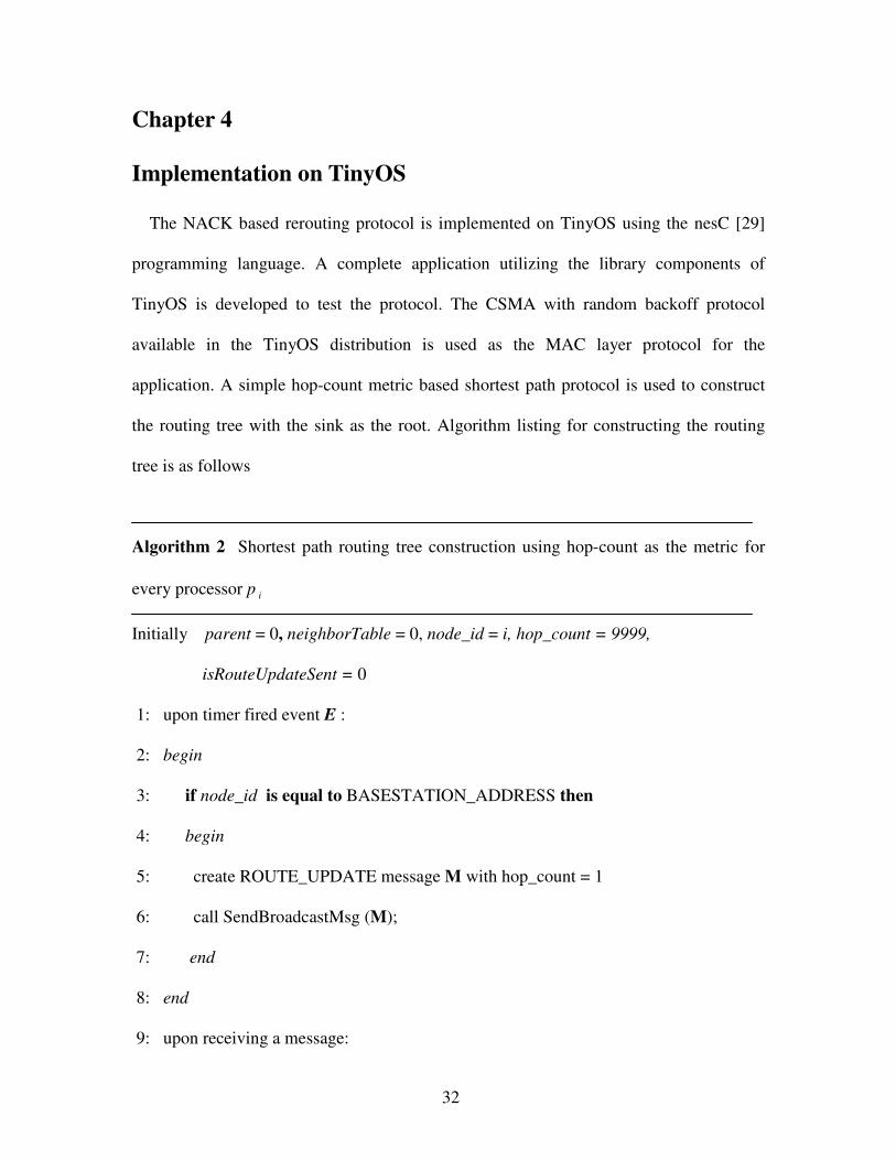
Chapter 4
Implementation on TinyOS
The NACK based rerouting protocol is implemented on TinyOS using the nesC [29]
programming language. A complete application utilizing the library components of
TinyOS is developed to test the protocol. The CSMA with random backoff protocol
available in the TinyOS distribution is used as the MAC layer protocol for the
application. A simple hop-count metric based shortest path protocol is used to construct
the routing tree with the sink as the root. Algorithm listing for constructing the routing
tree is as follows
Algorithm 2 Shortest path routing tree construction using hop-count as the metric for
every processor p i
Initially parent = 0, neighborTable = 0, node_id = i, hop_count = 9999,
isRouteUpdateSent = 0
1: upon timer fired event E :
2: begin
3: if node_id is equal to BASESTATION_ADDRESS then
4: begin
5: create ROUTE_UPDATE message M with hop_count = 1
6: call SendBroadcastMsg (M);
7: end
8: end
9: upon receiving a message:

33
10: begin
11: if message M is a ROUTE_UPDATE message then
12: begin
13: if M(hop_count) is less than hop_count then
14: begin
15: hop_count = M(hop_count);
16: create new ROUTE_UPDATE message M with hop_count value;
17: call SendBroadcastMsg (M);
18: end
19: end
4.1 Application Configuration
The application uses the following TinyOS library components –
(i) Main – The application begins its execution by running the
StdControl interface of this component.
(ii) GenericComm – This TinyOS library component is used for radio
communication. The SendMsg and ReceiveMsg interfaces are used
for sending and receiving messages. These interfaces abstract the
low level details of radio communication.
(iii) TimerC – This library component is used for generating timer
events. It can be set to fire timer events periodically or only once.
The Figure 4.1 describes the wiring of the components providing the interfaces and
components needing the interface. The ReliableRoute component of the application gets
an implementation of the Timer, SendMsg and ReceiveMsg interfaces by wiring to
TimerC and GenericComm components respectively.
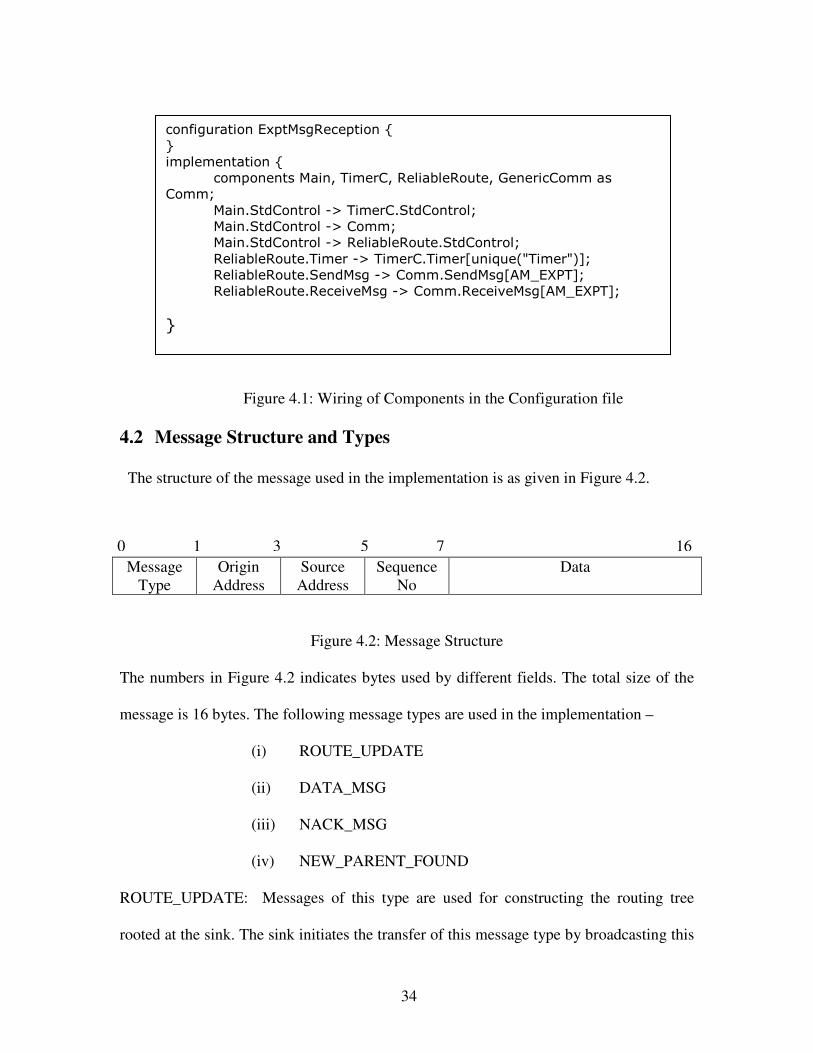
34
Figure 4.1: Wiring of Components in the Configuration file
4.2 Message Structure and Types
The structure of the message used in the implementation is as given in Figure 4.2.
Figure 4.2: Message Structure
The numbers in Figure 4.2 indicates bytes used by different fields. The total size of the
message is 16 bytes. The following message types are used in the implementation –
(i) ROUTE_UPDATE
(ii) DATA_MSG
(iii) NACK_MSG
(iv) NEW_PARENT_FOUND
ROUTE_UPDATE: Messages of this type are used for constructing the routing tree
rooted at the sink. The sink initiates the transfer of this message type by broadcasting this
Message
Type
Origin
Address
Source
Address
Sequence
No
Data
configuration ExptMsgReception {
}
implementation {
components Main, TimerC, ReliableRoute, GenericComm as
Comm;
Main.StdControl -> TimerC.StdControl;
Main.StdControl -> Comm;
Main.StdControl -> ReliableRoute.StdControl;
ReliableRoute.Timer -> TimerC.Timer[unique("Timer")];
ReliableRoute.SendMsg -> Comm.SendMsg[AM_EXPT];
ReliableRoute.ReceiveMsg -> Comm.ReceiveMsg[AM_EXPT];
}
0 1 3 5 7 16

35
message to all its one-hop neighbors with the value of the hop_count field set to 1. The
value 1 indicates that the receiver is 1 hop away from the sink. Every node on receiving a
ROUTE_UPDATE message updates the Neighborhood table by including the sender of
the message and the hop count value in the message. Also, every node once broadcasts
the ROUTE_UPDATE message with its hop count value.
DATA_MSG: Messages of this type is used by the nodes to send, receive and forward
data. On receiving this message the node adds it to the data buffer.
NACK_MSG: A node sends NACK messages when it is unable to forward the data
messages it received from its neighbors. It sends a NACK message for every message
stored in the data buffer to source node of that message.
NEW_PARENT_FOUND: This message is sent by a node to its new parent after it
chooses the new parent from the neighborhood table on receiving a NACK message from
its old parent. This message type is useful in preventing loop formation in the routing
structure. For example, if node A and node B have chosen a node C as its parent during
the initial routing path establishment and if node C fails by losing its link to its parent or
is unable to forward the messages collected in its data buffer then it sends a NACK
message to both node A and node B. The NEW_PARENT_FOUND message is sent by
either node A or node B if it chooses the other as its parent. If node B receives this
message from A, it blacklists node A so that it does not choose it to be its parent.
4.3 Event Handling
The application needs to provide event handlers for the following events –
(i) Send Done event: This event is generated when the message is successfully
sent by the underlying MAC layer. Figure 4.2 shows the code snippet for the
sendDone event handler. sendDone event handler declaration is part of the
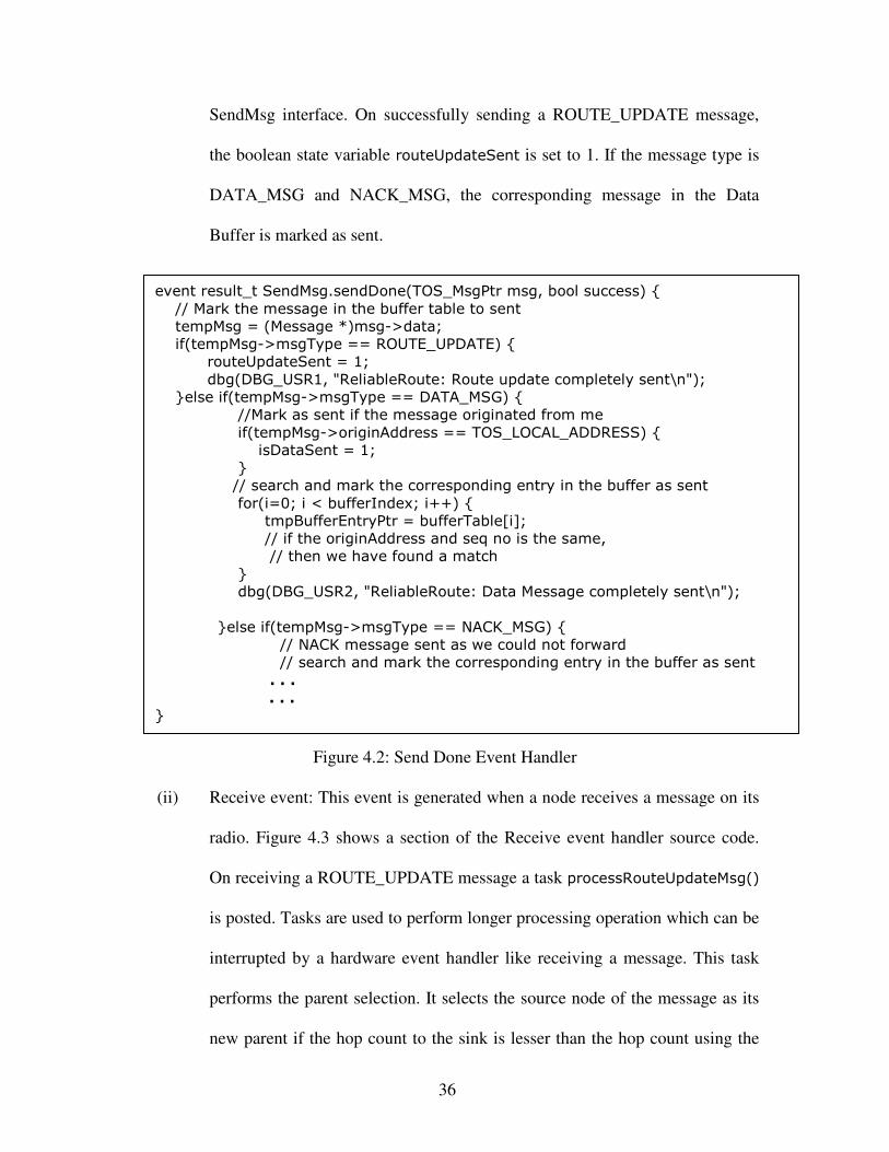
36
SendMsg interface. On successfully sending a ROUTE_UPDATE message,
the boolean state variable routeUpdateSent is set to 1. If the message type is
DATA_MSG and NACK_MSG, the corresponding message in the Data
Buffer is marked as sent.
Figure 4.2: Send Done Event Handler
(ii) Receive event: This event is generated when a node receives a message on its
radio. Figure 4.3 shows a section of the Receive event handler source code.
On receiving a ROUTE_UPDATE message a task processRouteUpdateMsg()
is posted. Tasks are used to perform longer processing operation which can be
interrupted by a hardware event handler like receiving a message. This task
performs the parent selection. It selects the source node of the message as its
new parent if the hop count to the sink is lesser than the hop count using the
event result_t SendMsg.sendDone(TOS_MsgPtr msg, bool success) {
// Mark the message in the buffer table to sent
tempMsg = (Message *)msg->data;
if(tempMsg->msgType == ROUTE_UPDATE) {
routeUpdateSent = 1;
dbg(DBG_USR1, "ReliableRoute: Route update completely sent\n");
}else if(tempMsg->msgType == DATA_MSG) {
//Mark as sent if the message originated from me
if(tempMsg->originAddress == TOS_LOCAL_ADDRESS) {
isDataSent = 1;
}
// search and mark the corresponding entry in the buffer as sent
for(i=0; i < bufferIndex; i++) {
tmpBufferEntryPtr = bufferTable[i];
// if the originAddress and seq no is the same,
// then we have found a match
}
dbg(DBG_USR2, "ReliableRoute: Data Message completely sent\n");
}else if(tempMsg->msgType == NACK_MSG) {
// NACK message sent as we could not forward
// search and mark the corresponding entry in the buffer as sent
. . .
. . .
}
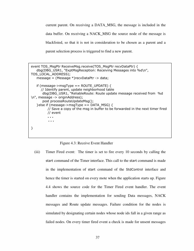
37
current parent. On receiving a DATA_MSG, the message is included in the
data buffer. On receiving a NACK_MSG the source node of the message is
blacklisted, so that it is not in consideration to be chosen as a parent and a
parent selection process is triggered to find a new parent.
Figure 4.3: Receive Event Handler
(iii) Timer Fired event: The timer is set to fire every 10 seconds by calling the
start command of the Timer interface. This call to the start command is made
in the implementation of start command of the StdControl interface and
hence the timer is started on every mote when the application starts up. Figure
4.4 shows the source code for the Timer Fired event handler. The event
handler contains the implementation for sending Data messages, NACK
messages and Route update messages. Failure condition for the nodes is
simulated by designating certain nodes whose node ids fall in a given range as
failed nodes. On every timer fired event a check is made for unsent messages
event TOS_MsgPtr ReceiveMsg.receive(TOS_MsgPtr recvDataPtr) {
dbg(DBG_USR1, "ExptMsgReception: Receiving Messages into %d\n",
TOS_LOCAL_ADDRESS);
message = (Message *)recvDataPtr -> data;
if (message->msgType == ROUTE_UPDATE) {
// Identify parent, update neighborhood table
dbg(DBG_USR1, "ReliableRoute: Route update message received from %d
\n", message -> originAddress);
post processRouteUpdateMsg();
}else if (message->msgType == DATA_MSG) {
// Save a copy of the msg in buffer to be forwarded in the next timer fired
// event
. . .
. . .
}

38
in the databuffer and one of it is sent. The checkUnSentMsgs() method
implements this.
Figure 4.4: Timer Fired Event Handler
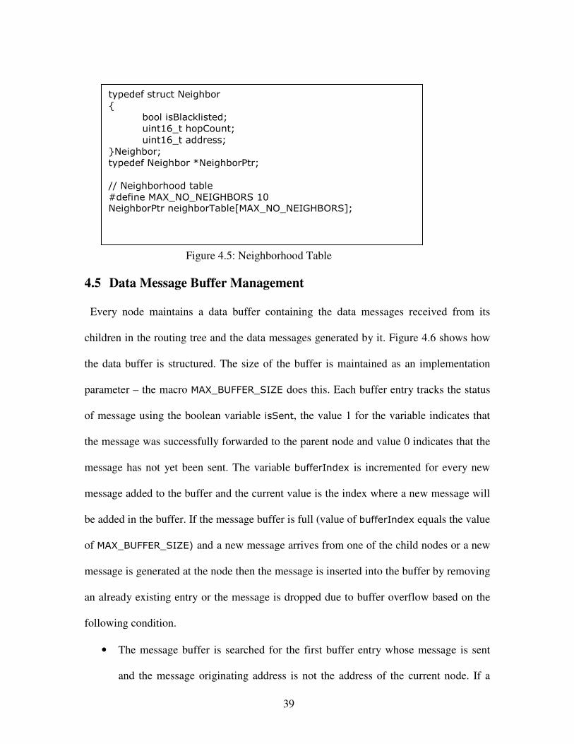
4.4 Neighborhood Table Management
Neighborhood table contains a list of structures having neighbor information. Figure 4.5
shows how the Neighborhood table is structured. Each neighborhood table entry contains
the address of the neighbor, hop count information to the sink and a Boolean state
variable indicating whether the neighbor is blacklisted or not. A blacklisted neighbor is
not considered for parent selection. The maximum number of entries in the neighborhood
table is defined as an implementation parameter – the MAX_NO_NEIGHBORS macro has
that information in Figure 4.5.
event result_t Timer.fired() {
timerCount++;
if(TOS_LOCAL_ADDRESS == BASESTATION_ADDRESS) {
isParentFound = 1;
if(!routeUpdateSent)
sendMessage(ROUTE_UPDATE);
}
else {
if(!isFailureCheckDone) {
isFailureCheckDone = 1;
if(TOS_LOCAL_ADDRESS > FAILING_NODE_BEGIN &&
TOS_LOCAL_ADDRESS < FAILING_NODE_END) {
// mark this node as a failed node - a node which
// fails to forward messages
isNodeFailed = 1;
}
}
checkUnSentMsgs();
}
return SUCCESS; }
39
Figure 4.5: Neighborhood Table
4.5 Data Message Buffer Management
Every node maintains a data buffer containing the data messages received from its
children in the routing tree and the data messages generated by it. Figure 4.6 shows how
the data buffer is structured. The size of the buffer is maintained as an implementation
parameter – the macro MAX_BUFFER_SIZE does this. Each buffer entry tracks the status
of message using the boolean variable isSent, the value 1 for the variable indicates that
the message was successfully forwarded to the parent node and value 0 indicates that the
message has not yet been sent. The variable bufferIndex is incremented for every new
message added to the buffer and the current value is the index where a new message will
be added in the buffer. If the message buffer is full (value of bufferIndex equals the value
of MAX_BUFFER_SIZE) and a new message arrives from one of the child nodes or a new
message is generated at the node then the message is inserted into the buffer by removing
an already existing entry or the message is dropped due to buffer overflow based on the
following condition.
• The message buffer is searched for the first buffer entry whose message is sent
and the message originating address is not the address of the current node. If a
typedef struct Neighbor
{
bool isBlacklisted;
uint16_t hopCount;
uint16_t address;
}Neighbor;
typedef Neighbor *NeighborPtr;
// Neighborhood table
#define MAX_NO_NEIGHBORS 10 NeighborPtr neighborTable[MAX_NO_NEIGHBORS];

40
buffer entry is found, then this entry no longer needs to be saved and hence
removed from the buffer and the new message is added into its position. If no
such buffer entry is found then the message is dropped.
Figure 4.6: Data Message Buffer Management
typedef struct Message
{
uint16_t msgType;
uint16_t sourceAddress;
uint16_t originAddress;
uint16_t seqNo;
uint8_t RFIDDataArray[9];
}Message;
typedef struct BufferEntry
{
bool isSent;
Message *msg;
}BufferEntry;
typedef BufferEntry *BufferEntryPtr;
// Buffer table
#define MAX_BUFFER_SIZE 15
BufferEntryPtr bufferTable[MAX_BUFFER_SIZE]; uint8_t bufferIndex = 0;

41
Chapter 5
Evaluation and Results
The implementation of the NACK based rerouting protocol described in Chapter 4 is
used for evaluation. The TOSSIM simulator is used for running the simulations.
5.1 Simulation Setup
A complete TinyOS application is written to simulate the protocol. Hop-count to the sink
is the cost metric considered for establishing the routing paths from different nodes to the
sink. The following parameters are considered for evaluation
• Network size or the number of nodes. The network topology considered for
evaluation is the grid topology.
• Simulation time in seconds. The simulation time is set long enough for routing
paths to be established and data sources forwarding the information. The
simulation time needed depends directly on the network size.
• Percentage of link and node failures. A subset of nodes in the network is set to
fail. Failure condition for the node is that it cannot forward any messages towards
the sink.
• Number of data generating sources in the network.
The above set of parameters are varied and compared against the percentage of messages
successfully received at the base station. The performance of NACK based rerouting
protocol is compared against NACK based retransmission mechanism for providing
reliability. RMST [4] in cached mode uses NACK based retransmission along the routing
path when a segment of the block that is being transmitted is missing. A lossy model is
used for describing the network connectivity for simulations. A file that describes the
42
lossy model is used for running simulations. This file has entries in the format “x:y:0.0” –
which indicates that link (x,y) experiences no losses, or “x.y:0.5” which indicates that
the probability of packet loss in the link (x,y) is 50%. A network grid size of m by n has
m × n such entries. A program is written to generate such a file such that the links to the
adjacent nodes in the same column and row have zero link loss probability and links to all
other nodes does not exist.
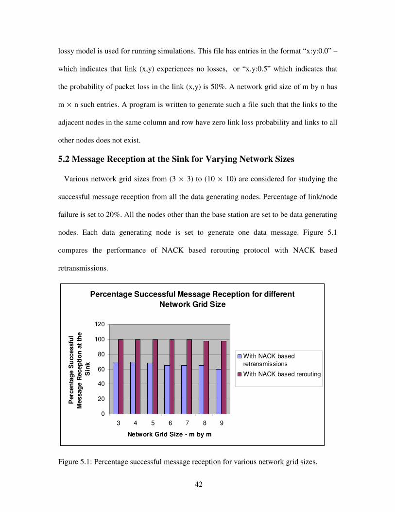
5.2 Message Reception at the Sink for Varying Network Sizes
Various network grid sizes from (3 × 3) to (10 × 10) are considered for studying the
successful message reception from all the data generating nodes. Percentage of link/node
failure is set to 20%. All the nodes other than the base station are set to be data generating
nodes. Each data generating node is set to generate one data message. Figure 5.1
compares the performance of NACK based rerouting protocol with NACK based
retransmissions.
Percentage Successful Message Reception for different
Network Grid Size
0
20
40
60
80
100
120
3 4 5 6 7 8 9
Network Grid Size - m by m
Perc
en
tag
e S
uccessfu
l
Messag
e R
ecep
tio
n a
t th
e
Sin
k
With NACK based
retransmissions
With NACK based rerouting
Figure 5.1: Percentage successful message reception for various network grid sizes.

43
It can be seen in Figure 5.1 that the NACK based rerouting mechanism guarantees near
100% reliable packet reception. The successful packet reception rate is not exactly 100%
as there are scenarios where some nodes are unable to select a new parent on receiving a
NACK message from its current parent as all the entries in the neighborhood table are
blacklisted.
5.3 Message Reception at the Sink for varying Percentage of Link
Failures The percentage of failed links in the network is varied from 5% to 50% for studying
the successful message reception percentage. A 7×7 grid deployment is considered and
80% of the nodes are data generating nodes. Each source generates one data message to
be forwarded to the sink.
Percentage Successful message reception for different
Percentage of link failures
0
20
40
60
80
100
120
5 10 15 20 30 40 50
Percentage of failed links
Perc
en
tag
e S
uccessfu
l
messag
e r
ecep
tio
n a
t th
e s
ink
With NACK based
retransmissions
With NACK based
rerouting
Figure 5.2: Percentage Successful Message Reception for different percentage of failed
links
Figure 5.2 gives a comparison of NACK based retransmissions and NACK based
rerouting schemes. NACK based rerouting scheme guarantees near 100% reliability until

44
the number of failed links is 30%, after this the percentage successful packet reception
falls. This is due to nodes being unable to select new parent from the neighborhood table
on receiving a NACK message. This happens when all the nodes in the neighborhood
table of any particular node is blacklisted.
5.4 Message Reception at the Sink for Varying Network Traffic
A 7×7 grid deployment is considered and the network traffic is varied by increasing
the percentage of data generating nodes from 20% to 100%. Percentage of link failures is
kept constant at 30%. Figure 5.3 shows a comparison of NACK based rerouting scheme
to the NACK based retransmission scheme.
Percentage Successful message reception for different
Percentage of data generating nodes
0
20
40
60
80
100
120
20 30 40 50 60 70 80 90 100
Percentage of data generating nodes
Perc
en
tag
e S
uccessfu
l
messag
e r
ecep
tio
n a
t th
e s
ink
With NACK based
retransmissions
With NACK based
rerouting
Figure 5.3: Percentage Successful Message Reception for different percentage of data
generating nodes
NACK based rerouting scheme in Figure 5.3 achieves near 100% successful packet
reception at the sink for increasing percentage of data generating sources as the nodes are
successful in establishing alternate routing paths on receiving NACKs from their parent

45
nodes. With NACK based retransmission scheme, the successful packet reception
decreases at the sink as failed links indicate broken routing path and the nodes on
receiving NACKs only retransmit the message back to the parent and hence the messages
are not successfully forwarded to the sink.
Percentage Successful message reception for different
data generation rates
0
20
40
60
80
100
120
1 2 4 6 8
Number of data messages generated at
every timer fired event
Perc
en
tag
e S
uccessfu
l
messag
e r
ecep
tio
n a
t th
e s
ink
With NACK based
retransmissions
With NACK based
rerouting
Figure 5.4: Percentage Successful Message Reception for different data generation rates
Figure 5.4 shows the comparison of NACK based rerouting protocol with NACK
based retransmission mechanism when the network traffic is varied by increasing the data
generation rate. The timer is set to fire every 5 seconds and the number of data messages
generated on every timer fired event is varied. Each data generating node generates data
messages for the first 5 timer fired events. A 7×7 grid deployment is considered and the
simulation time is fixed at 200 seconds. A fraction of the time is taken for routing path
establishment. 50% of nodes are designated as data generating nodes and 25% of nodes
are set to fail.

46
The percentage successful message reception at the sink in Figure 5.4 decreases with
increased data generation rate for NACK based rerouting data delivery scheme as some
packets are dropped by the intermediate nodes due to data buffer overflow. With NACK
based retransmission scheme, the successful packet reception is even lesser as packets are
lost along the routing path due to broken links and also due to packets being dropped as
there is buffer overflow at the intermediate nodes due to increased data generation rates.
Percentage Successful message reception for different simulation time
duration under constant data generation rate
0
20
40
60
80
100
120
100 150 200 250 300
Simulation time duration in seconds
Perc
en
tag
e S
uccessfu
l m
essag
e
recep
tio
n a
t th
e s
ink
With NACK basedretransmissions
With NACK based rerouting
Figure 5.5: Percentage Successful Message Reception under increasing simulation
time duration
Figure 5.5 shows the performance comparison of NACK based rerouting and NACK
based retransmissions in terms of successful message reception at the sink under constant
data generation rate for increasing simulation time duration. A grid deployment of 7×7
is considered with 50% of nodes generating data messages at a constant rate of 3 data
messages for every timer fired event. The timer is set to fire once every 5 second time
interval. The number of failed links is set to 20%. The NACK based rerouting protocol is
able to consistently achieve higher percentage of successful packet reception as the

47
intermediate nodes are able to manage the data buffer effectively by successfully
sending/forwarding the data messages. The number of packets dropped due to buffer
overflow at the nodes is lesser than under increasing data generation rate as in Figure 5.4.

48
Chapter 6
Conclusion and Future Work
6.1 Conclusion
In this thesis we have developed a cross-layer based mechanism with MAC layer
retransmissions and NACK based rerouting of data packets for providing guaranteed
reliability of sensors-to-sink single packet delivery. The implementation of the protocol
as an application on TinyOS is described. Extensive simulations of the protocol are done
on TOSSIM to compare the performance in terms of successful packet reception at the
sink with NACK based retransmission scheme for the metrics – varying network sizes,
network traffic and percentage of link failures. The NACK based rerouting protocol
developed provides much better reliability than NACK based retransmission protocol.
6.2 Future Work
This work can be extended in the following way
• A realistic experimental scenario can be established to study the reliable transfer
of RFID tag messages by using RFID readers mounted on sensing nodes and
considering different rates of data generation that depends on the actual factory
warehouse setting.

49
Bibliography
[1] C. Wan, A. Campbell, L. Krishnahmurthy. PSFQ: A Reliable Transport Mechanism
for Wireless Sensor Networks. ACM International Workshop On Wireless Sensor
Networks and Applications, Atlanta, Georgia. Sept 2002.
[2] Y. Sankarasubramaniam, O. B. Akan, and I. F. Akyildiz, “ESRT: Event-to-sink
reliable transport in wireless sensor networks,” presented at the ACM MobiHoc,
Annapolis, MD, Jun. 2003.
[3] A. Woo, T. Tong, D. Culler. “Taming the Underlying Challenges of Reliable
Multihop Routing in Sensor Networks”, SenSys ’03, Los Angeles, California, USA.
[4] R. Stann and J. Heidemann, “RMST: Reliable data transport in sensor networks,” in
Proc. 1st IEEE Int. Workshop Sensor Net Protocols Appl. (SNPA), Anchorage, AK,
May 2003, pp. 102–112.
[5] S. Madden. M. Franklin, and J. Hellentein. TAG a Tiny Agregation Service for Ad-
Hoc Sensor Networks. OSDI. Dec 2002.
[6] M. Marin-Perianu, P. Havinga. “Experiments with Reliable Data Delivery in
Wireless Sensor Networks” in Proc. Intelligent Sensors, Sensor Networks and
Information Processing Conference, 2005, pp. 109 - 114
[7] TinyOS Homepage [Online]. Available: http://webs.cs.berkeley.edu/tos/
[8] J. Hill, R. Szewczyk, A.Woo, S. Hollar, D. Culler, and K. Pister, “System
architecture directions for network sensors,” in Proc. 9th Int. Conf. Arch.Support
Program.Languages Oper. Syst., Nov. 2000, pp. 93–104.
[9] Gnawali, O.; Yarvis, M.; Heidemann, J.; Govindan, R. “Interaction of retransmission,
blacklisting, and routing metrics for reliability in sensor network routing”. Sensor
and Ad Hoc Communications and Networks, 2004. IEEE SECON 2004. Page(s):34 –
43
[10] D. Tian and N. D. Georganas, “Energy efficient routing with guaranteed delivery in
wireless sensor networks,” in Proc. IEEE Wireless Communications and Networking
Conference 2003 (WCNC’03), Institute of Electrical and Electronics Engineers. New
Orleans, USA: IEEE Press, Mar. 2003.
[13] A.Woo and D. Culler, “A transmission control scheme for media access in sensor
networks,” in Proc. ACM/IEEE Int. Conf. Mobile Computing and Networking,
Rome, Italy, July 2001, pp. 221–235.

50
[14] Wei Ye, John Heidemann and Deborah Estrin, "Medium Access Control with
Coordinated, Adaptive Sleeping for Wireless Sensor Networks," IEEE/ACM
Transactions on Networking, Vol. 12, No. 3, June 2004.
[15] Wei Ye, John Heidemann and Deborah Estrin, "A Flexible and Reliable Radio
Communication Stack on Motes," USC/ISI Technical Report ISI-TR-565.
[16] B. Deb, S. Bhatnagar, and B. Nath, “Information assurance in sensor networks,” in
Proc. 2nd ACM Intl. Workshop on Wireless Sensor Networks and Applications
(WSNA), San Diego, CA, Sept. 2003.
[17] D. Ganesan, R. Govindan, S. Shenker, and D. Estrin, “Highly-Resilient, Energy-
Efficient Multipath Routing in Wireless Sensor Networks,” Mobile Computing and
Communications Review (MC2R), vol. 1, no. 2, 2002.
[18] D. Tian and N. D. Georganas, “Energy efficient routing with guaranteed delivery
in wireless sensor networks,” in Proc. IEEE Wireless Communications and
Networking Conference 2003 (WCNC’03), Institute of Electrical and Electronics
Engineers. New Orleans, USA: IEEE Press, Mar. 2003.
[19] B. Deb, S. Bhatnagar, and B. Nath, “Reinform: Reliable information forwarding
using multiple paths in sensor networks,” in Proc. 28th Annual IEEE Conference on
Local Computer Networks (LCN 2003), 20-24 Oct. 2003 Page(s):406 - 415.
[20] S.-J. Park, R. Vedantham, R. Sivakumar, and I. F. Akyildiz, “A scalable approach
or reliable downstream data delivery in wireless sensor networks,” in Proc.
Symposium on Mobile Ad Hoc Networking & Computing (MobiHoc’01), Tokyo,
Japan, May 2004.
[21] S.-J. Park and R. Sivakumar, “Poster: Sink-to-sensors reliability in sensor
networks,” in Proc. 4th ACM Intl. Symp. onMobile Ad Hoc Networking and
Computing (MOBIHOC), Annapolis, MD, June 2003.
[22] C. Intanagonwiwat, R. Govindan, D. Estrin, J. Heidemann, and F. Silva, “Directed
diffusion for wireless sensor networks,” IEEE/ACM Transactions on Networking,
vol. 11, no. 1, pp. 2–16, Feb. 2003.
[23] C. Englund and H. Wallin. RFID in wireless sensor network. In C. U. of
Technology, editor, Master's Thesis, Gotenborg, Sweden, April 2004.
[24] McKelvin, M. L., Williams, M. L., and Berry, N. M. 2005. Integrated radio
frequency identification and wireless sensor network architecture for automated
inventory management and tracking applications. In Proceedings of the 2005
Conference on Diversity in Computing (Albuquerque, New Mexico, USA, October
19 - 22, 2005). TAPIA '05. ACM Press, New York, NY, 44-47.
[25] Crossbow Inc Homepage [Online]. Available: www.xbow.com

51
[26] D. Gay, P. Levis, R. von Behren, M. Welsh, E. Brewer, and D. Culler, “The nesC
language: A holistic approach to networked embedded systems,” in SIGPLAN
Conference on Programming Language Design and Implementation (PLDI’03),
June 2003.
[27] A. Woo and D. Culler. Evaluation of efficient link reliability estimators for low-
power wireless networks. Technical Report UCB//CSD-03-1270, U.C. Berkeley
Computer Science Division, September 2003.
[28] E. D. Demaine, A. Lopez-Ortiz, and J.I.Munro. Frequency estimation of internet
packet streams with limited space. In Proceedings of the 10th Annual European
Symposium on Algorithms ESA 2002, pages 348–360, September 2002.
[29] David Gay, Philip Levis, David Culler, and Eric Brewer. necC 1.1 language
reference manual. http://nescc.sourceforge.net/papers/nesc-ref.pdf, May 2003
[30] Philip Levis, Nelson Lee, Matt Welsh, and David Culler. TOSSIM: Accurate
and scalable simulation of entire tinyos applications. Proceedings of the ACM
Symposium on Networked Embedded Systems, Nov 2003.
[31] Mainwaring, Alan. Polastre, Joseph. Szewczyk, Robert. Culler, David. Anderson,
John. Wireless Sensor Networks for Habitat Monitoring. First ACM Workshop on
Wireless Sensor Networks and Applications. September 28, 2002. Atlanta, GA,
USA.

52
Vita
Ravilochan G Shamanna received his Bachelor of Engineering degree in computer
science and engineering from Visvesvaraya Technological University, India, in 2002. He
joined the Department of Computer Science at Louisiana State University, Baton Rouge,
to pursue his master’s degree in systems science in January 2005. His research interest is
in the area of distributed wireless sensor networks. He is a candidate for the degree of
Master of Science in Systems Science to be awarded at the commencement of December
2006.