study of overloading effects, in a refrigerated display case · refrigeration system and...
TRANSCRIPT
1
Study Of Overloading Effects, In A Refrigerated Display Case
Sandeep Palaksha Senior CAE Engineer
HUSSMANN Basavanagudi
Bangalore – 04, India [email protected]
Narasimhamurthy CAE Engineer HUSSMANN
Basavanagudi Bangalore – 04, India
Keywords: Return Air, Discharge Air, Evaporator, Simulator
Abstract
HUSSMANN provides user manual to its customers as a guideline on how to use and operate HUSSMANN refrigerated display
cases. But customers never follow and it Impacts Display case performance also in turn reduces shelf life of food products. The main cause which effects efficiency of the refrigerated display case is overloading. HUSSMANN has done a market research on overloading and captured all variations of overloading in CFD, to study and analyze its effects on airflow and
thermal behavior inside the display case. CFD is beneficial in achieving accurate results and reduce cycle time of conventional Lab testing. This was done using HyperMesh to build mathematical model and AcuSolve to simulate the Lab conditions.
With the CFD analysis and information, power consumption were calculated based on Evaporator load data. This shows how much money customers can save, just by following instructions to load display cases as in outlined in user manual.
Introduction Hussmann is enabling excellence in food retailing by providing innovative solutions in areas such as merchandising, energy efficiency and sustainability, food quality and integrity, refrigeration, design and engineering, service and installation, and improving retail performance. HUSSMANN is passionate about food retailing and have a relentless dedication to our customers' success.
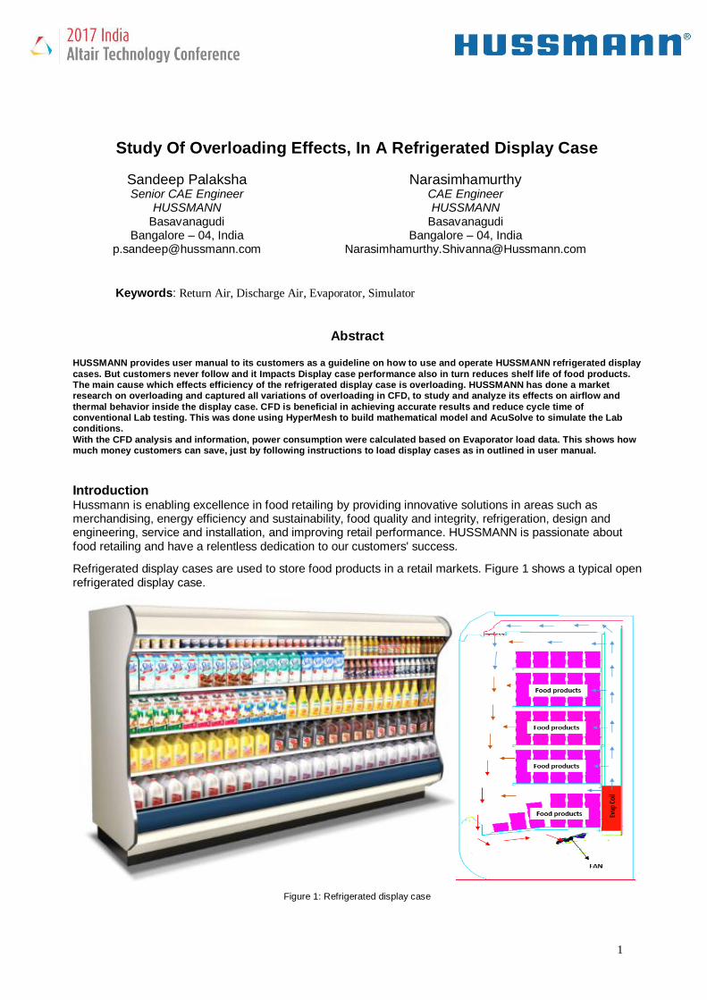
Refrigerated display cases are used to store food products in a retail markets. Figure 1 shows a typical open refrigerated display case.
Figure 1: Refrigerated display case

2
Working phenomenon of refrigerated display case: - Axial fan draws air from the case and pushes it over the evaporator coil, where air will get cooled and that cold air is supplied into the case where the products are placed, so that the product temperature will be maintained across the case.
Objective of the project:
✓ To understand the air flow behavior inside the refrigerated display case unit and study the impact of
overloading on case performance and evaporator coil using CFD.
✓ Validate the CFD prediction with test data in terms of air flow distribution and product temperature.
Process Methodology (details with figures) As the refrigerated display case unit is symmetrical, one four foot section was considered for the CFD simulation.
Figure 2: Three fan 12foot case Figure 3: One fan 4foot case
What is Overloading:-
Overloading is an extra load on the shelf or in the case. The loading operation given by the catalog or in the instructions not being followed is also a type of over load.
Overloading examples:-
From market research collected some overloading examples which they found in some stores, Figure 4 shows standard and overloading conditions. In standard loading all the products are uniformly distributed and followed standard loading criteria. In case – 1 customer overloaded the case in such a way that the cold air coming from the moiré holes was blocked, due to this blockage cold air cannot enter the case and required temperature may not be achieved. In case – 2 customer overloaded the case where the return air grill is blocked, due to the blockage in return air there will be more infiltration which affects the performance of the evaporator and the case.

3
Figure 4: Overloading examples
Overloading types:-
Based on market research information, Created three different type of overloading cases in CFD to study how it affects the efficiency and performance of the case. Figure 5 shows standard and all three different types of overloading. Side view of the refrigerated display case:-
Figure 5: Overloading types
If we are to believe in simulation then results must be verified to establish a baseline.

4
Performed a preliminary CFD simulation for a standard loading to check the physics of the air flow inside the cabinet and test lab. CFD simulation was then constructed to validate the virtual results with actual results achieved in the test lab. Grid development:
Altair HyperMesh used for surface mesh and then that surface mesh was imported in AcuConsole to generate solid tet. The dimensions of computations space is shown in figure 6. To capture boundary layer phenomena accurately, 5 layers were generated on all surfaces with first layer height as 0.1 mm and growth rate as 1.3. Fine and irregular grid at test lab air domain was used for accurate commutation. Total mesh size was 30 Mn. tetrahedral elements.
Figure 6: Volume mesh
Load and Boundary condition:
> Constructed complete exact model in CFD. To simulate exact physics we have included radiation and thermal equations in the simulation.
> Products are captured with standard dimensions and with correct numbers. > Calculated heat flux from evaporator coil in and out temperature data measured in test lab, than that
values are used in CFD evaporator coil modeling. > For all the components Emissivity values are assigned to capture the radiation effects. > Air material model considered as Boussinesq to capture the effect of density change. Air temperature
inside the case and test lab varies from 75 ̊F to 22 ̊F so that the density effects need to be captured. > Pressure drop of the coil is captured by modeling it as porous media. > Fan is modeled as 3D model with capturing correct geometry so that it could deliver the required air
flow.

5
> Lab discharge and return air path are captured properly.
Figure 7: CFD model
Numerical methodology:
In this work, the Navier-Stokes equations were solved using AcuSolve, a commercially available flow solver
based on the Galerkin/Least-Squares (GLS) finite element method. AcuSolve is a general purpose CFD flow
solver that is used in a wide variety of applications and industries. The flow solver provides fast and
accurate transient and steady state solutions for standard unstructured element topologies. AcuSolve
ensures local conservation for individual elements. Equal-order nodal interpolation is used for all working
variables, including pressure and turbulence equations. The resultant system of equations is solved as a
fully coupled pressure/velocity matrix system using a preconditioned iterative linear solver. The iterative
solver yields robustness and rapid convergence on large unstructured meshes even when high aspect ratio
and badly distorted elements are present.
The following forms of the Navier-Stokes equations were solved by AcuSolve to simulate the flow inside the PROTOIRE refrigeration system:

6
Due to low mach number involved in these simulation, the flow was assumed to be incompressible, and the
density time derivative in Eq. (1) was set to zero. The three dimensional steady flow is simulated using
RANS single equation Spalart-Allmaras turbulence model. The turbulence equation is solved using GLS
formulation. The model equation is as follows:
For the steady state solutions presented in this work, a first order time integration approach with infinite time
step size was used to iterate the solution to convergence. Steady state convergence was typically reached
within 500 time steps.
Results & Discussions: All the results displayed are averaged values not the exact values
Base line model:
Performed CFD simulation for the base line model using accurate load and boundary conditions.
Figure 8: Thermal vector and contour plot in ̊ F

7
Figure 8 shows the temperature or thermal vector and contour plots in ̊F and figure 9shows temperature comparison of test lab data with CFD simulation data.
Figure 9: Test Vs CFD comparison
> If we observe the above comparison plots, the trend is matching and temperatures are almost matching with the test lab results. Only 2 to 3 °F difference can be observed.
> More deviation can be observed in the right hand side of the products simulators.
> We have not modelled the velocity profile change in the coil w.r.t time. But in reality before the defrost cycle there may be ice formation in the coil which will reduce the flow rate. It is difficult to capture this physics because of its complexity. If we could capture this in the simulation more accurate results could be achieved.
Now that we have proven the validity and theory behind our model, simulation was performed on all the cases.
Figure 10: Velocity plot in m/s
Figure 10 shows velocity plot of all the cases, In Standard Loading most of the case air is entering inside the return air grill. In Overloading Type – 1, 2 and 3 some of the air is exiting from the case to ambient which will affect the performance
8
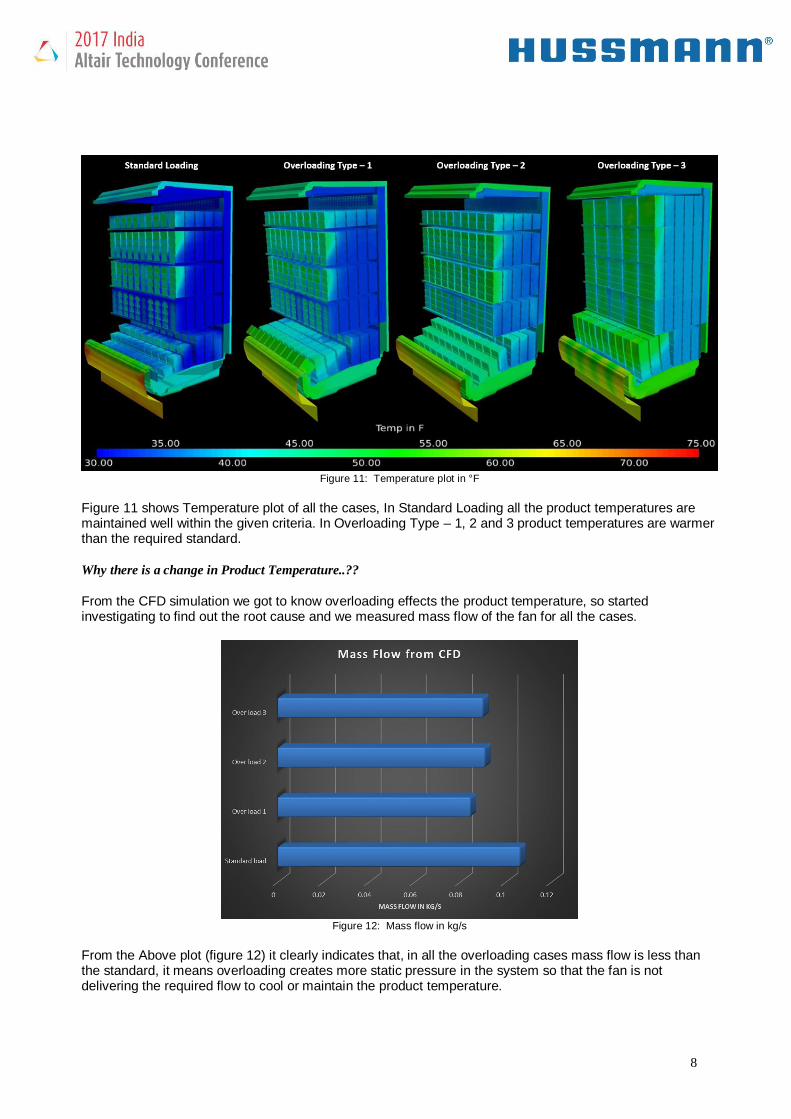
Figure 11: Temperature plot in °F
Figure 11 shows Temperature plot of all the cases, In Standard Loading all the product temperatures are maintained well within the given criteria. In Overloading Type – 1, 2 and 3 product temperatures are warmer than the required standard.
Why there is a change in Product Temperature..??
From the CFD simulation we got to know overloading effects the product temperature, so started investigating to find out the root cause and we measured mass flow of the fan for all the cases.
Figure 12: Mass flow in kg/s
From the Above plot (figure 12) it clearly indicates that, in all the overloading cases mass flow is less than the standard, it means overloading creates more static pressure in the system so that the fan is not delivering the required flow to cool or maintain the product temperature.

9
Benefits Summary
From this CFD simulation data we calculated evaporator loading condition of each case and calculated energy consumed for each loading condition case.
Figure 13: Metrics
Figure 13 shows how we calculated energy consumed in kWh and how much money spend per year to run a four foot refrigerated display case in Missouri State USA. From the above metric it clearly indicates that overloading cases consume more energy than the standard loading case. if we consider $50 as average savings for one four foot per year then in supermarket like Walmart, Costco and Target there will be min of 100 four foot cases means minimum of $5000 savings per year by just fallowing loading instruction manual. With the help of AcuSolve, Leading commercial finite element CFD code, we at HUSSMANN product development team quickly take a decision, whether we go for existing new design or suggested design, without doing manual test which is expensive. And it was very useful for us to do parametric study by varying overloading conditions without spending much time as it was in physical test.
Challenges
• Maintaining element count was big challenge. Ended up with 30 Million cell count.
• Each Final model took 140hours .i.e. almost 6days to converge.
• System configuration used DELL PRECISION, 128GB RAM, 10CORE.
• Lot of experiment, study, discussion, and approximately 10+ iterations carried out before achieving
the final results.
.

10
Conclusions From the above CFD simulations it clearly shows that how product over loading effects the refrigerated display case performance and how energy/money can be saved by just fallowing Hussmann instruction manual to load the refrigerated display case.
ACKNOWLEDGEMENTS
The authors would like to thank Mr. Kamlesh, Abinash & Sanjay, Altair technical support and Mr. Balakrishna, Abhijith, Lead Engineer-Modeling&Simulation, Ingersoll Rand and B C Jyothirmaya, Manager-Refrigeration System HUSSMANN for their valuable support and contributions during this project. We also would like to thank Mr. Krishna, Mudumby, General Manager, and HUSSMANN Services India LLP for allowing us to publish this paper.
REFERENCES:
1. Refrigeration and Air Conditioning Technology by Bill Whitman (Author), Bill Johnson (Author), John Tomczyk (Author), Eugene Silberstein (Author), Whitman (Author), Larry Johnson (Author), Tomczyk (Author), Silberstein (Author)
2. Refrigeration System and Application by Ibrahim Dincer (Author), Mehmet Kanoglu (Author)