study of coupler's effects on ilc like...
TRANSCRIPT

STUDY OF COUPLER’S EFFECT ON ILC LIKE LATTICE
A. Saini, K.Ranjan, University of Delhi, Delhi, India A. Latina, A. Lunin, N.Solyak, S. Mishra, V. Yakovlev, Fermilab, IL 60510, U.S.A.
Abstract It is well known that insertion of a coupler into a rf cavity breaks the rotational symmetry of the cavity, resulting in an asymmetric field. This asymmetric field results in a transverse RF Kick. This RF kick transversely offsets the bunch from the nominal axis & it depends on the longitudinal position of the particle in the bunch. Also, insertion of coupler generates short range transverse wake field which is independent from the transverse offset of the particle. These effects cause emittance dilution and it is thus important to study their behaviour & possible correction mechanisms. These coupler effects, i.e. coupler’s RF kick & coupler's wake field are implemented in a beam dynamics program, Lucretia. Simulations are performed for main linac & bunch compressor of International Linear Collider (ILC) like lattices. Results are compared with analytical results and another beam dynamics code Placet. The good agreement has been achieved.
INTRODUCTION In a future linear collider such as International Linear
Collider, design of main linac will be based on TESLA technology . The each TESLA cavity is supplied with one main power coupler and two Higher Order Mode (HOM) coupler. The location and orientation of couplers are shown in Fig 1.
Figure 1: The ILC RF cavity with main & HOM couplers. The insertion of coupler in cavity might generate asymmetries in the field which causes transverse kick to beam. The coupler kick is classified in two category i.e. coupler rf kick which is due to asymmetry in field and coupler wake kick. It degrades beam quality and causes dilution of beam emittance. This dilution will adversely affect luminosity at the interaction point. It is worth to say that vertical emittance is consider for all calculation as vertical tolerances are higher than horizontal from
luminosity point of view. In this work, we will study coupler’s effects in ILC like main linac and ILC like two stage bunch compressor by using beam dynamics code Lucretia [1]. These coupler’s effects are already implemented in Lucretia and presented in [2]. The studied has also done for compensation technique. One-to-one steering & girder kick optimization are utilized to compensate the coupler’s kick. The benchmarking is done with analytical model [3] and another beam dynamics code Placet.
Coupler RF Kick It has been shown that coupler’s rf kick can be expressed as a complex quantity, i.e. ~
y /Va e(iφ+ ks ) where Vy is transverse voltage, Va is accelerating voltage, s is position of particle, k is wave no. & φ is RF phase. This kick can be written as sum of real and imaginary component V∼ = Vreal + i Vimag where real part of coupler kick acts on the bunch as a whole so It can be compensated by using nominal beam based alignment (BBA) technique like 1:1 but imaginary part of kick deflects the particles depending on the position of particles w.r.t. centre of the bunch. It means that particles at different position in bunch get kick which is not only different in magnitude but direction too, depending on the position of particle in bunch w.r.t centre. In Lucretia, the deflection of particle due to coupler kick can be expressed dPy = [Vreal cos(φ +ks) – Vimag sin(φ +ks)]*G*.L/(P*c); (1) where G is gradient & L is length of cavity. The magnitude of coupler rf kick for upstream and downstream coupler is same for all accelerating structures so its effect adds coherently along the accelerator. The coupler kick is calculated by using numerical code [4] and summarized in Table 1.
Table 1: RF Kick for the Couplers of ILC Cavity Vreal Vimag Upstream -48.3e-6 -3.4e-6 Downstream 41.0e-6 14.5e-6 Total 7.3e-6 11.1e-6
Coupler Wake Kick Calculation of coupler wake has been done by using
numerical code. The wake field function is calculated for Gaussian bunches. Coupler wake is independent from the transverse offset and wake kick depends only longitudinal position of particles w.r.t. bunch centre. It has been implemented in Lucretia [2]. The deflection of particle due to coupler wake kick can be expresses as
dPy=W(s)*Q/P; (2) where Q is total charge of the bunch, P is momentum of particle, s is longitudinal postion of particles in the bunch and W(s) is the wake function at this position. The
V= V
Proceedings of IPAC’10, Kyoto, Japan THPD088
05 Beam Dynamics and Electromagnetic Fields
D01 Beam Optics - Lattices, Correction Schemes, Transport 4491

analytical estimation has been done for emittance dilution under the effects of coupler transverse kicks. It shows that, in a uniform focusing lattice under the effect of a constant transverse RF kick, the emittance grows as follows:
(3) Where ε0 is the initial emittance, F is the first derivative of the kick, for z = 0, σ is the bunch length, β is the betatron amplitude, U0 is the initial energy and & γ the corresponding relativistic factor. It is convenient to study this formula in two regimes: in presence and in absence of acceleration. In absence of acceleration, γ (z) =γ0, the growth of the emittance vanishes if the cosine term is equal to 1, that is when z/β=2πn where n is an integer. In presence of acceleration the oscillatory behavior of the emittance persists, but there is a residual emittance growth that cannot be avoided. This can be understood by considering that the potential well of the focusing force is shifted by the RF kick and its offset decays faster than the oscillation radius ( 1/ γ << (1/ γ) 1/2 . The pictorial presentation is shown in Fig.2.
Figure 2: Phase diagrams for different betatron phases for particle belonging to different transverse bunch cross sections: head (red), center (green), and tail (blue). The emittance of the entire bunch is shown in yellow. Left and right hand sides show the cases without- and with- acceleration.
MAIN LINAC The simulation for coupler’s effects has been done for main linac. The TESLA lattice is used for the study of main linac. The calculation is done only for understanding the coupler’s effects. It means all study is done for perfect machine i.e. no misalignments and with ideal beam position monitor. To understand the coupler’s effect in more details, study of coupler’s rf kick and coupler‘s wake kick are done separately and their collective behaviour is also studied. The important parameters which are used for the simulation of main linac is summarized in Table 2. The Fig. 3 shows emittance growth along the main linac due to coupler transverse rf kick only. The result is compared with Placet and a very good agreement is achieved between two code. The
studied is also done for emittance compensation. The one-to-one steering is applied. The 1:1 is a correction beam Table 2: Parameters Used for Calculation in Main Linac
Parameters Magnitude Units Length of Cavity 1.036 Meter RF phase in Cavity 5.1 Degree Gradient 31.5 MV/m Initial Emittance 20 nan rad Length of Linac ~8.7 km Bunch Charge 3.2 nC No. of FODO cells 100 - Energy spread within bunch 0.0107 % Bunch Length 300 μm
Based alignment (BBA) correction technique in which position of bunch centre is measured and kicks are applied to correct the trajectory of the beam by using correctors. The kick is proportional to transverse displacement of the bunch centre from the axis.
Figure 3: Emittance behaviour of the beam in main linac when complete coupler kick (�=-7.3e-6+i 11.1e-6) is applied. The emittance growth after 1:1 correction for above case is shown in Fig. 4. It is expected that 1:1 correction can not compensate emittance dilution due to imaginary part
Figure 4. Figure 5.
of kick as it does not give any kick to bunch centre but the other particles. It is confirmed by comparing the residual beam emittance after 1:1 and beam emittance afte applying only imaginary part of coupler kick. The result is shown in Fig. 5. The emittance growth in main linac due to coupler wake is calculated. The coupler wake kick has same nature as imaginary part of coupler kick and it also can not be corrected by using BBA technique. The results are shown in Fig. 6.
THPD088 Proceedings of IPAC’10, Kyoto, Japan
4492
05 Beam Dynamics and Electromagnetic Fields
D01 Beam Optics - Lattices, Correction Schemes, Transport
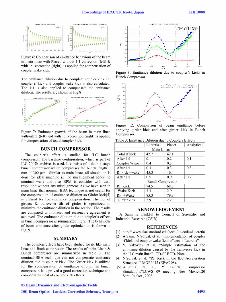
Figure 6: Comparison of emittance behaviour of the beam in main linac with Placet, without 1:1 correction (left) & with 1:1 correction (right) is applied for compensation of coupler wake kick. The emittance dilution due to complete coupler kick i.e. coupler rf kick and coupler wake kick is also calculated. The 1:1 is also applied to compensate the emittance dilution. The results are shown in Fig.8
Figure 7: Emittance growth of the beam in main linac without1:1 (left) and with 1:1 correction (right) is applied for compensation of toatal coupler kick.
BUNCH COMPRESSOR The coupler’s effect is studied for ILC bunch
compressor. The baseline configuration, which is part of ILC 2007b archive, is used. It consists of a double stage bunch compressor which compresses the bunch length 6 mm to 300 μm. Similar to main linac, all simulation is done for ideal machine i.e. no misalignment hence no nominal wake and also BPM is consider with zero resolution without any misalignment. As we have seen in main linac that nominal BBA technique is not useful for the compensation of emittance dilution so Girder kick[5] is utilized for the emittance compensation. The no. of girders & transverse tilt of girder is optimized to minimize the emittance dilution in the section. The results are compared with Placet and reasonable agreement is achieved. The emittance dilution due to coupler’s effects in bunch compressor is summarized Fig.8. The behaviour of beam emittance after girder optimization is shown in Fig. 9.
SUMMARY The couplers effects have been studied for ilc like main
linac and Buch compressor. The results of main Linac & Bunch compressor are summarized in table 3. The nominal BBA technique can not compensate emittance dilution due to coupler kick. The Girder kick is utilized for the compensation of emittance dilution in bunch compressor. It is proved a good correction technique and compensates most of coupler kick effects.
Figure 8: Emittance dilution due to coupler’s kicks in Bunch Compressor.
Figure 12: Comparison of beam emittance before applying girder kick and after girder kick in Bunch Compressor.
Table 3: Emittance Dilution due to Couplers Effects Lucretia Placet Analytical Main Linac Total rf kick 42.7 42.1 After 1:1 0.1 0.2 0.1 Coupler Wake 0.4 0.3 After 1:1 0.3 0.3 0.3 Rf kick +wake 45.3 46.4 After 1:1 0.5 0.9 0.7 Bunch Compressor RF Kick 74.5 68.7 Wake Kick 3.3 2.9 RF +Wake 85.3 79.3 Girder kick 2.9 2.2
AKNOWLEDGEMENT A Saini is thankful to Council of Scientific and
Industrial Research (CSIR).
REFERENCES [1] http:// www.slac.stanford.edu/accel/ilc/codes/Lucretia [2] A.Saini, N.Solyak et al, “Implementation of coupler
rf kick and coupler wake field effects in Lucretia” [3] V. Yakovlev et al, “Simple estimation of the
emittance dilution caused by the transverse kick in the ILC main linac”. TD-SRF TD- Note.
[4] N.Solyak et al, ”RF Kick in the ILC Acceleration Structure. ” MOPP042 (EPAC 08).
[5] A.Latina et al, “ Bunch Compressor Simulations”LCWS 09 meeting New Mexico.20 Sept- 04 Oct., 2008.
Proceedings of IPAC’10, Kyoto, Japan THPD088
05 Beam Dynamics and Electromagnetic Fields
D01 Beam Optics - Lattices, Correction Schemes, Transport 4493