study of behaviors of electronic amplifiers using nichols
TRANSCRIPT

Gunma
Kobayashi
Laboratory
Gunma University, Japan
Study of Behaviors of Electronic
Amplifiers using Nichols Chart
PHD. Candidate. MinhTri Tran*,
Prof. Anna Kuwana, Prof. Haruo Kobayashi

1. Research Background• Motivation, objectives and achievements
• Self-loop function in a transfer function
2. Analysis of Behaviors of High-order Systems• Operating regions of high-order systems
3. Ringing Test for Feedback Amplifiers• Stability test for shunt-shunt feedback amplifiers
• Stability test for unity-gain and inverting amplifiers
4. Ringing Test for High-order Low-Pass Filters• Stability test for passive and active RLC circuits
• Stability test for Deboo low-pass filters
5. Conclusions
Outline

2
1. Research BackgroundNoise in Electronic Systems
Ringing does the following things:
• Causes EMI noise,
• Increases current flow,
• Decreases the performance, and
• Damages the devices.
STABILITY TEST
Unstable system
Signal to
Noise Ratio:
Performance of a devicePerformance of a system
Figure of
Merit:=
Signal powerSNR
Noise power=
Output SNR
Input SNRF
Common types of noise:
• Electronic noise, thermal noise, intermodulation noise,
cross-talk, flicker noise, thermal noise...

3
o Derivation of self-loop function based on the
proposed comparison measurement
o Investigation of operating regions of linear
negative feedback networks
o Observation of phase margin at unity gain on
the Nichols chart
à Over-damping (high delay in rising time)
à Critical damping (max power propagation)
à Under-damping (overshoot and ringing)
1. Research BackgroundObjectives of Study

4
1. Research BackgroundAchievements of Study
Comparison measurement
• Feedback amplifiers
• High-order low-pass filters
Alternating current conservationIncident
current
Transmitted
current
2nd-order Deboo low-pass LPF
input
output
Implemented circuit
1()
)(
( )ww = -
wA
HL
Self-loop
function

5
1. Research BackgroundSelf-loop Function in A Transfer Function
( ( )
(( )
)
)
)
1
(out
in
HV
V
A
L
w= =
+w
www
Transfer function
( )L w
( )A w( )H w
: Numerator function
: Transfer function
: Self-loop function
Linear system
Input Output( )H w
( )winV ( )woutV
0 1
0 1
( ) ... ( )
()
) ... ((
)
n
n n
n
n n
Hb j b j b
a j a j a
w w
w ww
-
-
+ + +=
+ + +
Model of a linear system
oMagnitude-frequency plot
oAngular-frequency plot
oPolar chart à Nyquist chart
oMagnitude-angular diagram à Nichols diagram
Bode plots
Variable: angular frequency (ω)

6
1. Research BackgroundComparison Measurement
Transfer functionSelf-loop function
1()
)(
( )ww = -
wA
HL
Sequence of steps:
(i) Measurement of
numerator function A(ω),
(ii) Measurement of transfer
function H(ω), and
(iii) Derivation of self-loop
function.
1 (
( )
(
(
)
)
)( )w =
w=
+www
out
in
A
L
V
VH
Linear system
Input Output
( )H w( )winV ( )woutV
0 1
0 1
( ) ... ( )
()
) ... ((
)
n
n n
n
n n
Hb j b j b
a j a j a
w w
w ww
-
-
+ + +=
+ + +
Model of a linear system

7
1. Research BackgroundAlternating Current Conservation
( ) 1
( )1
;(
( )
)
in
o
i
ut
in
o
ou
n
ut
tHZ
Z
Z
V
L
V
Z
w= =
w +
Þ =
w
w
Transfer function
Simplified linear system
Self-loop function
( )inc trans in
t
c
tra
in
i u nsn o t ou
V ZL
Z Z
V
VZ
VwÞ-= = - =
Incident
current
Transmitted
current
10 mH
inductance
Derivation of self-loop function

8
1. Research BackgroundCharacteristics of Adaptive Feedback Network
Block diagram of a typical adaptive feedback system
Reference voltage
Adaptive feedback is used to control the output source along with the
decision source (DC-DC Buck converter).
Transfer function of an adaptive feedback network is significantly
different from transfer function of a linear negative feedback network.
à Loop gain is independent of frequency variable (referent voltage,
feedback voltage, and error voltage are DC voltages).
DC voltage
DC voltage
DC voltage
DC voltage
+ Ripple voltage
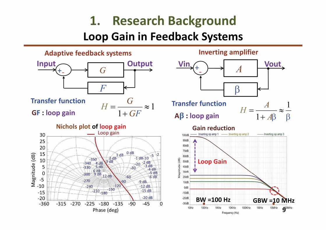
BW =100 Hz GBW =10 MHz
Loop Gain
9
1. Research BackgroundLoop Gain in Feedback Systems
Aβ : loop gain
Transfer function 1
1= »
+ b bA
AHGF : loop gain
Transfer function1
1= »
+GFG
H
G
F
+-
OutputInputA+
-
VoutVin
b
Inverting amplifierAdaptive feedback systems
Nichols plot of loop gain Gain reduction

1. Research Background• Motivation, objectives and achievements
• Self-loop function in a transfer function
2. Analysis of Behaviors of High-order Systems• Operating regions of high-order systems
3. Ringing Test for Feedback Amplifiers• Stability test for shunt-shunt feedback amplifiers
• Stability test for unity-gain and inverting amplifiers
4. Ringing Test for High-order Low-Pass Filters• Stability test for passive and active RLC circuits
• Stability test for Deboo low-pass filters
5. Conclusions
Outline

Case Over-damping Critical damping Under-damping
Delta
Module
Angular
11
2. Analysis of Behaviors of High-order SystemsCharacteristics of 2nd-order Transfer Function
( )D0
2
211 0
0
14 0
2
æ ö< Þ D = - >ç ÷è ø
aa a
a a0
2
211 0
0
14 0
2
æ ö= Þ D = - =ç ÷è ø
aa a
a a0
2
211 0
0
14 0
2
æ ö> ÞD = - <ç ÷è ø
aa a
a a
( )wH2
0
1 1 1
2 22
2 2 1
0 0 0 0 0 0
1
1 1
2 2 2 2
æ ö æ öæ ö æ öç ÷ ç ÷w + - - w + + -ç ÷ ç ÷ç ÷ ç ÷è ø è øè ø è ø
a
a a a a
a a a a a a0
20
2 1
1 1 1
2
2
6= =é ùæ öê úw + ç ÷
-
ê úè øë û
dBa a
a
0
1 1 1 1
0 0 0
2
0 0
22 2 2
0
2
1
1 1
2 2 2 2
æ ö æ öæ ö æ ö æ ö æ öç ÷ ç ÷w- - + w+ - +ç ÷ ç ÷ ç ÷ ç ÷ç ÷ ç ÷è ø è ø è ø è øè ø è ø
a
a a a a
a a a a a a
( )q w 1 1 1 1
0 0
2
0 0
2
0 0
arctan arctan
1 1
2 2 2 2
æ ö æ öç ÷ ç ÷ç ÷ ç ÷w w
- -ç ÷ ç ÷ç ÷ ç ÷æ ö æ ö
- - + -ç ÷ ç ÷ç ÷ ç ÷ç ÷ ç ÷è ø è øè ø è ø
a a a a
a a a a a a
0
1
22 arctan
æ öwç ÷- ç ÷è ø
a
a
1 1
0 0 0 0
1 1
0 0
2 2
1 1
2 2arctan arctan
2 2
æ ö æ öæ ö æ öç ÷ ç ÷w- - w+ -ç ÷ ç ÷ç ÷ ç ÷è ø è ø- -ç ÷ ç ÷ç ÷ ç ÷ç ÷ ç ÷ç ÷ ç ÷è ø è ø
a a
a a a a
a a
a a
1
02w =cut
a
a0
1
( )2
w <cut
a
aH ( )
2
pq w > -cut
1
0( )2
w =cut
a
aH ( )
2
pq w = -cut
0
1
( )2
w >cut
a
aH ( )
2
pq w < -cut
0
2
1
1
1 ( )( ) =
+ w + ww
ja a jHSecond-order transfer function:

Case Over-damping Critical damping Under-damping
Delta
12
2. Analysis of Behaviors of High-order SystemsCharacteristics of 2nd-order Self-loop Function
( )D 2
1 04 0D = - >a a 2
1 04 0D = - =a a2
1 04 0D = - <a a
( )wL ( )2 2
0 1w w +a a ( )2 2
0 1w w +a a ( )2 2
0 1w w +a a
( )q w 0
1
arctan2
wp+
a
a0
1
arctan2
wp+
a
a0
1
arctan2
wp+
a
a
11
0
5 22
w = -a
a1 1( )w >L
1) .3( 76p - q w > o
1 1( )w =L 1) .3( 76p - q w = o1 1( )w <L 1) .3( 76p - q w < o
12
02w =
a
a 25( )w >L 2 ) .4( 63p - q w > o
2 5( )w =L 2 ) .4( 63p-q w = o
2 5( )w <L 2 ) .4( 63p - q w < o
0
31w =a
a 32( 4)w >L
345( )p-q w > o
32( 4)w =L 3
45( )p-q w = o3 2( 4)w <L 3
45( )p - q w < o
[ ]0 1( ) = w w+w aj j aLSecond-order self-loop function:

13
2. Analysis of Behaviors of High-order SystemsOperating Regions of 2nd-Order System
98o103.7o
128o
Nichols plot of self-loop functionBode plot of transfer function
Transient response
0dB
-12dB
-6dB
Phase
margin
52o
( )
( )
( )
21
2
3
2
2
1;1
1;1
1;
( )
( )
( )
2
3 1
j
j
j
j
j
j
H
H
H
=w + +
=w + +
w
w
w+
w
=w +
w
w
•Under-damping:
•Critical damping:
•Over-damping:
( )21 ;( ) w= ww +j jL
( )22 ;( 2) = w w+w j jL
( )23 ;( 3) = w w+w j jL
Phase
margin
92o
Phase
margin
76.3o
1. Research Background• Motivation, objectives and achievements
• Self-loop function in a transfer function
2. Analysis of Behaviors of High-order Systems• Operating regions of high-order systems
3. Ringing Test for Feedback Amplifiers• Stability test for shunt-shunt feedback amplifiers
• Stability test for unity-gain and inverting amplifiers
4. Ringing Test for High-order Low-Pass Filters• Stability test for passive and active RLC circuits
• Stability test for Deboo low-pass filters
5. Conclusions
Outline

15
3.Ringing Test for Feedback AmplifiersAnalysis of Shunt-Shunt Feedback Amplifier
[ ]11
0
2
00
1
;( ) 1
( ( ))w+
= = = w w+w +
w+ w
wout
in
Hj
b baL
V j
V jaj a
aj
( )( ) ( )
0 1 01 1 1 1 1 1 1 1
1 1 1 1 1 11
; ; ;
;
= = - = + +
= + + + +
L GD L m S L GD GS GD DB DB GS
L GD DB S GS GD S L m GD
R C Rb g R R C C C C C C
R C C R C g
a
C R R C
b
a
BJT shunt-shunt feedback amplifier Small signal model
Transfer function and self-loop function
Where,
1 1 1 1 1 1 1 1 1 1 1; ;in out
out m
s C F C s C C CCS C o C F
V VV V V g
R r Z R Z R Z Z Z R r Z Rp p
p p m m m m
æ ö æ ö æ ö+ + + + = + + + + = + -ç ÷ ç ÷ ç ÷ç ÷ ç ÷ ç ÷
è ø è ø è ø
Apply superposition at the nodes Vπ and Vout, we have
16
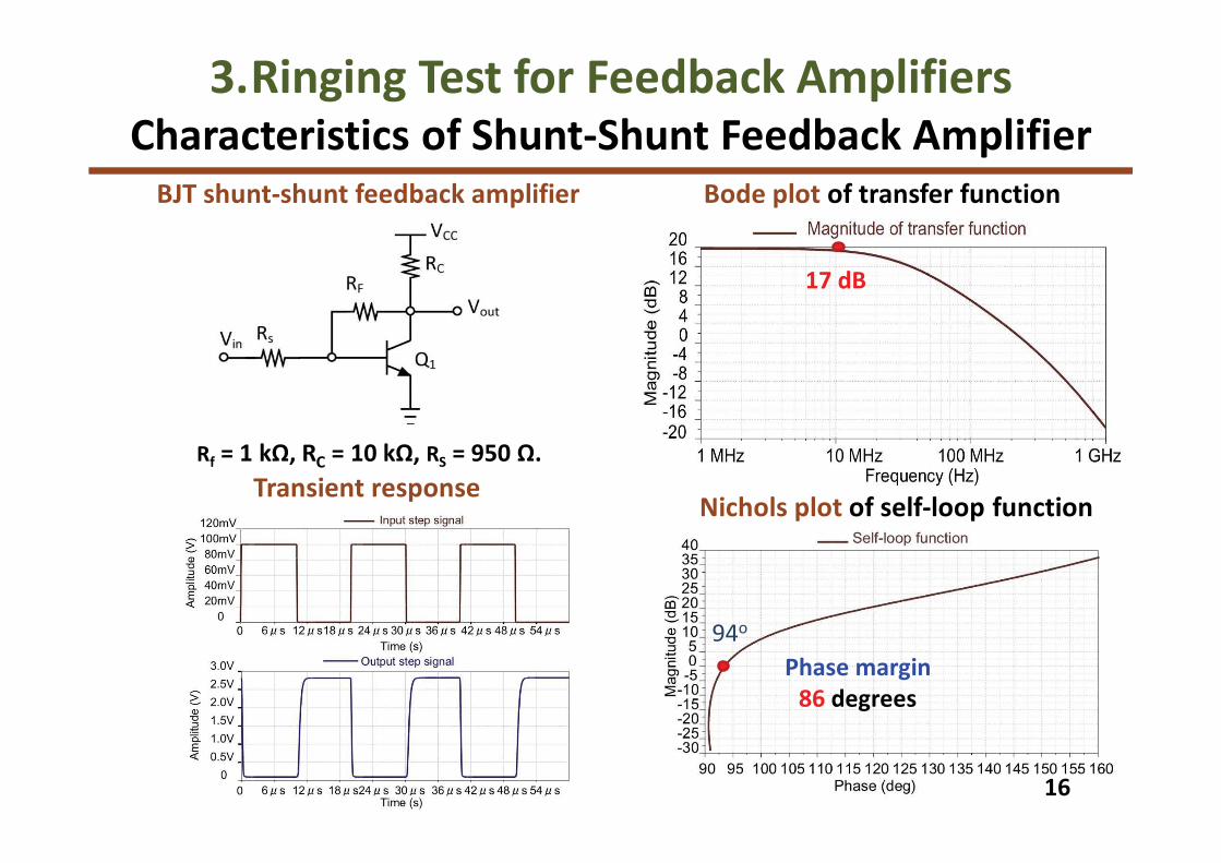
3.Ringing Test for Feedback AmplifiersCharacteristics of Shunt-Shunt Feedback Amplifier
BJT shunt-shunt feedback amplifier
Nichols plot of self-loop function
Bode plot of transfer function
Transient response
94o
Phase margin
86 degrees
17 dB
Rf = 1 kΩ, RC = 10 kΩ, RS = 950 Ω.

17
Without frequency compensation
Small signal model of 2nd-stage
Transfer function
( ) 1
2
0 1
0
;)1
(w +
=w + w +
wb b
a ja
j
jH
( )( )
( ) ( )
2
0 1
0
1
; ;
;
;
= = -
é ù= + + -ë û
é ù= + + + +ë û
D GD D m
D S GD DB GS GD GD
D GD DB S GS GD D S m GD
a R C R g
R R C C C C C
R C C R
a
C R g C
b
b C R
Where,
3.Ringing Test for Feedback AmplifiersAnalysis of Op Amp without Miller’s Capacitor
Open-loop function
( ) ( )( ) ( ) ( )
0 1 2 3
0
3 2
4 3 2
1 2 3
;( )1
w + w + w+=
w + w + ww
+ w+op
b bA
b b
a a a
j j j
j j j ja
Self-loop function
( ) ( ) ( )4 2
2
3
0 1 3 ;( ) = w + w + w + wwop j j ja a a jaL
( )0 1
2( ) = w + ww ja a jL
Self-loop function

18
Bode plot of transfer function H(ω)
Nichols plot of self-loop function L(ω)
Unity-Gain Amplifier
Transient response
167o
Phase margin = 13 degrees
3.Ringing Test for Feedback AmplifiersUnity-Gain Amplifier without Miller’s Capacitor
15 dB

19
With Miller’s capacitor and resistor
( ) ( )( ) ( ) ( )
2
0 1 2 3
0 3
4
1
3
2
3 2;)1
(w w + w+
=w + w + w + w
+
+w
b b b b
aH
j j j
j a ja j a j
( ) ( ) ( )0 1
2
2
4
3
3( ) = w + w + w + ww j j ja a a a jL
3.Ringing Test for Feedback AmplifiersTwo-stage Op Amp with Frequency Compensation
Open-loop function
( ) ( ) ( ) ( )( ) ( ) ( ) ( ) ( )
5 4 3
5
2
6
0 1 2 3 4
0 1 2 3 4
4
5
5 3 2;(1
)w + w + w + w + w+
=w + w + w + w + w + w+
wopA
j j j j j
j j j j j
b b b b b b
a a a a a ja
Self-loop function
( ) ( ) ( ) ( ) ( )6 5
0 1 2 3 4
4 3 2
5 ;( ) = w + w + w + w ww + + wop j j jL a a a a aj j ja
Transfer function
Self-loop function
Small signal model of 2nd-stage

20
Unity-gain amplifier with Miller’s capacitor
3.Ringing Test for Feedback AmplifiersUnity-Gain Amplifier with Miller’s Capacitor
Under-damping:
R1= 2 kΩ, C1 = 1 pF
Critical damping:
R1 = 3.5 kΩ, C1 = 0.2 pF
Over-damping:
R1 = 3.5 kΩ, C1 = 0.8 pF
( )
( )
( )( )
1 11; ;
11
= » =w
w
w w+
LA
A
H
Transfer function and self-loop function
Simplified model

21
150o
90o
79o
Nichols plot of self-loop functionBode plot of transfer function
3.Ringing Test for Feedback AmplifiersBehaviors of Unity-Gain Amplifier
Simulated transient responseSimplified model of unity gain amplifier
-9 dB
5 dB
-15dB
PM
30o
PM
90oPM
101o
22
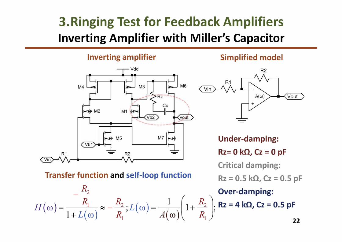
Inverting amplifier
3.Ringing Test for Feedback AmplifiersInverting Amplifier with Miller’s Capacitor
Under-damping:
Rz= 0 kΩ, Cz = 0 pF
Critical damping:
Rz = 0.5 kΩ, Cz = 0.5 pF
Over-damping:
Rz = 4 kΩ, Cz = 0.5 pF( )( )
( )( )
2
1 2 2
1 1
1; 1 ;
1
æ ö= » = +ç ÷+ w
w-
è ø-
ww LH
R
R R
RL A
R
R
Transfer function and self-loop function
Simplified model

23
139o
111o106o
Nichols plot of self-loop functionBode plot of transfer function
3.Ringing Test for Feedback AmplifiersBehaviors of Inverting Amplifier
Simulated transient responseSimplified model of inverting amplifier
20dB
4dB
8dBPM
41o
PM
74o
PM
69o
5 dB
15 dB
-10 dB

1. Research Background• Motivation, objectives and achievements
• Self-loop function in a transfer function
2. Analysis of Behaviors of High-order Systems• Operating regions of high-order systems
3. Ringing Test for Feedback Amplifiers• Stability test for shunt-shunt feedback amplifiers
• Stability test for unity-gain and inverting amplifiers
4. Ringing Test for High-order Low-Pass Filters• Stability test for passive and active RLC circuits
• Stability test for Deboo low-pass filters
5. Conclusions
Outline

25
4. Ringing Test for High-order Low-Pass FiltersAnalysis of 2nd-Order Passive RLC LPF
Passive RLC Low-pass Filter
( )0 1
2
1;( )1
out
in
VH
jaV ja= =
+ w +w
w
Derivation of self-loop function
( )0
2
1 ;( )L aja j= +w w w
Self-loop function
Implemented circuit
Transfer function
0 1; ;= =a LC RCawhere,

26
4. Ringing Test for High-order Low-Pass FiltersMeasurement Results for 2nd-Order Passive RLC LPF
Transient responses
94o 107o122o
Nichols plot of self-loop function
Bode plot of transfer function
2dB
-10dB
0dB
PM
68o
PM
86o
PM
73o

27
4. Ringing Test for High-order Low-Pass FiltersStability Test for 2nd-Order Active Ladder LPF
Implemented circuit
( )0 1
2
1;( )1
out
in
VH
jaV ja= =
+ w +w
w
Transfer function
( )0
2
1 ;( )L aja j= +w w w
Self-loop function
Active ladder low-pass filter
107o
117o 133o
Nichols plot of self-loop functionBode plot of transfer function
7dB
-7dB
-3dB
PM
47o
PM
73o
PM
63o

28
4. Ringing Test for High-order Low-Pass FiltersAnalysis of 2nd-Order Deboo low-pass LPF
( )( )
( ) ( )
2
0
1
2
0
0 1
;1
;
=w + w+
= w +
w -
w w
jH
j
b
aL
a
a j
a
j
( )( ) ( )
( ) ( )( )( ) ( )
2 4 7 5 6
1 2 4 5 6 7 4 5 3 6
2 3 4 5 7 1 2
2 4 5 6 7 4 5 3 6
2 7 1 4 5 3 6 3 4 5 7 2
2 4 5 6 7 4 5 3 6
0
0
1
;
;
;
+=
é ù+ + -ë û
=+ + -
- +=
+ + -
R R R R R
R R R R R R R R R R
R R R R R C C
R R R R R R R R R
R R C R R R R R
b
R R R C
R R R R R R Ra
R
a
R
Single ended Deboo low-pass LPF Transfer function & self-loop function
where,
R1 = R3 = R5 = 1 kΩ, R2 = 10 kΩ, R6 = R7 = 5
kΩ, C1 = 1 nF, C2 = 0.5 nF at f0 = 10 kHz.
• Over-damping (R4 = 3 kΩ),
• Critical damping (R4 = 6 kΩ), and
• Under-damping (R4 = 10 kΩ).
Fully differential Deboo low-pass LPF

29
4. Ringing Test for High-order Low-Pass FiltersImplemented Circuit of Deboo low-pass LPF
Schematic of Deboo low-pass LPF
System Under Test Measurement set up
Implemented Circuit

30
4. Ringing Test for High-order Low-Pass FiltersMeasurement Results of Deboo low-pass LPF
Over-damping:
àPhase margin is 81 degrees.
Critical damping:
àPhase margin is 73 degrees.
Under-damping:
àPhase margin is 62 degrees.
Transient response
Bode plot of transfer function Nichols plot of self-loop function
99o 107o 118o
7 dB
-7 dB
0 dB
PM
62o
PM
81o
PM
73o

1. Research Background• Motivation, objectives and achievements
• Self-loop function in a transfer function
2. Analysis of Behaviors of High-order Systems• Operating regions of high-order systems
3. Ringing Test for Feedback Amplifiers• Stability test for shunt-shunt feedback amplifiers
• Stability test for unity-gain and inverting amplifiers
4. Ringing Test for High-order Low-Pass Filters• Stability test for passive and active RLC circuits
• Stability test for Deboo low-pass filters
5. Conclusions
Outline

32
5. Limitations of Conventional Methods
o Middlebrook’s measurement of loop gain
àApplying only in feedback systems (DC-DC converters).
o Replica measurement of loop gain
àUsing two identical networks (not real measurement).
o Nyquist’s stability condition
à Theoretical analysis for feedback systems (Lab tool).
o Nichols chart of loop gain
à Only used in feedback control theory (Lab tool).

5. Comparison
FeaturesComparison
measurement
Alternating
current
conservation
Replica
measurement
Middlebrook’s
method
Main objectiveSelf-loop
function
Self-loop
functionLoop gain Loop gain
Transfer function
accuracyYes Yes No No
Breaking feedback
loopNo Yes Yes Yes
Operating region
accuracyYes Yes No No
Phase margin
accuracyYes Yes No No
Passive networks Yes Yes No No

5. Discussions
• Loop gain is independent of frequency variable.
àLoop gain in adaptive feedback network is significantly
different from self-loop function in linear negative
feedback network.
https://www.mathworks.com/help/control/ref/nichols.html
Network Analyzer
Nichols chart is only used
in MATLAB simulation.
Nichols chart isn’t used widely in
practical measurements
(only used in control theory).
(Technology limitations)
This work:
• Proposal of comparison measurement for deriving
self-loop function in a transfer function
à Observation of self-loop function can help us
optimize the behavior of a high-order system.
• Implementation of circuit and measurements of self-
loop functions for high-order feedback amplifiers.
àTheoretical concepts of stability test are verified by
laboratory simulations and practical experiments.
Future of work:
• Stability test for parasitic components in transmission
lines, printed circuit boards, physical layout layers
5. Conclusions

References[1]L. Fan, Z. Miao, "Admittance-Based Stability Analysis: Bode Plots, Nyquist Diagrams or
Eigenvalue Analysis", IEEE Trans. on Power Systems, vol. 35, no. 4, July 2020.
[2]M. Liu, I. Dassios, G. Tzounas, F. Milano, “Stability Analysis of Power Systems with Inclusion of
Realistic-Modeling of WAMS Delays”, IEEE Trans. on Power Sys., vol.34, no.1, pp. 627-636, 2019.
[3]S. Zhong, Y. Huang, “Comparison of the Phase Margins of Different ADRC Designs,” IEEE Chinese
Control Conf., China, July 2019.
[4]H. Abdollahi, A. Khodamoradi, E. Santi, P. Mattavelli, "Online Bus Impedance Estimation and
Stabilization of DC Power Distribution Systems: A Method Based on Source Converter Loop-Gain
Measurement", IEEE Applied Power Electronics Conference and Exposition, LA, USA, June 2020.
[5]L. Fan, Z. Miao, “Admittance-Based Stability Analysis: Bode Plots, Nyquist Diagrams or
Eigenvalue Analysis?,” IEEE Trans. on Power Systems, vol. 35, no. 4, pp. 3312 – 3315, July 2020.
[6]Y. Ren, X. Wang, L. Chen, Y. Min, G. Li, L. Wang, Y. Zhang, “A Strictly Sufficient Stability Criterion
for Grid-Connected Converters Based on Impedance Models and Gershgorin's Theorem,” IEEE
Trans. on Power Delivery, vol. 35, no. 3, pp. 1606 – 1609, June 2020.
[7]V. Salis, A. Costabeber, S. Cox, F. Tardelli, P. Zanchetta, “Experimental Validation of Harmonic
Impedance Measurement and LTP Nyquist Criterion for Stability Analysis in Power Converter
Networks,” IEEE Trans. on Power Electronics, vol. 34, no. 8, pp. 7972 – 7982, Aug. 2019.
[8]S. Wang, B. Li, Z. Xu, X. Zhao, D. Xu, “A Precise Stability Criterion for Power Hardware-in-the-Loop
Simulation System,” 10th Int. Conf. on Power Electronics and ECCE Asia, Busan, Korea, May 2019.
[9]S. Plesnick, J. Berardino, R. Irwin, “The Generalized Nyquist Criterion Applied to Complex DC
Power System Networks,” IEEE Electric Ship Technologies Symposium, DC, USA, Aug. 2019.

References[10] J. Ardila, E. Roa, “A Novel Loop Gain Adaptation Method for Digital CDRs Based on the Cross-
Correlation Function,” IEEE Int. Symp. on Circuits and Systems, Sapporo, Japan, May 2019.
[11] A. Ochoa, D. Patterson, M. McGuckin, “Driving Point Loop Gain and Return Ratio,” IEEE 62nd
Int. Midwest Symposium on Circuits and Systems, TX, USA, Aug. 2019.
[12] M. Tran, A. Kuwana, H. Kobayashi, "Derivation of Loop Gain and Stability Test for Low Pass
Tow-Thomas Biquad Filter", 10th Int. Conf. on Computer Science, Engineering and Applications,
London, UK, July 2020.
[13] M. Tran, A. Kuwana, H. Kobayashi, "Ringing Test for Third-Order Ladder Low-Pass Filters", 11th
IEEE Annual Ubiquitous Computing, Electronics & Mobile Communication Conference, USA, 2020.
[14] N. Sayyaf, M. Tavazoei, “Frequency Data-Based Procedure to Adjust Gain and Phase Margins
and Guarantee the Uniqueness of Crossover Frequencies,” IEEE Trans. on Industrial Electronics,
vol. 67, no. 3, pp. 2176 – 2185, March 2020.
[15] M. Tran, A. Kuwana, H. Kobayashi, “Derivation of Loop Gain and Stability Test for Multiple
Feedback Low Pass Filter Using Deboo Integrator”, The 8th IIAE Int. Conf. on Industrial
Application Engineering, Shimane Japan, March, 2020.
[16] M. Liu, I. Dassios, F. Milano “On the Stability Analysis of Systems of Neutral Delay Differential
Equations”, Circuits, Systems, and Signal Processing, vol. 38, no. 4, pp. 1639-1653, 2019.
[17] M. Tran, A. Kuwana, H. Kobayashi, “Design of Active Inductor and Stability Test for Ladder RLC
Low Pass Filter Based on Widened Superposition and Voltage Injection”, The 8th IIAE Int. Conf. on
Industrial Application Engineering, Shimane Japan, March 2020.

Gunma
Kobayashi
Laboratory
Thank you very much!