study of beam dynamics of electron beam in a...
TRANSCRIPT
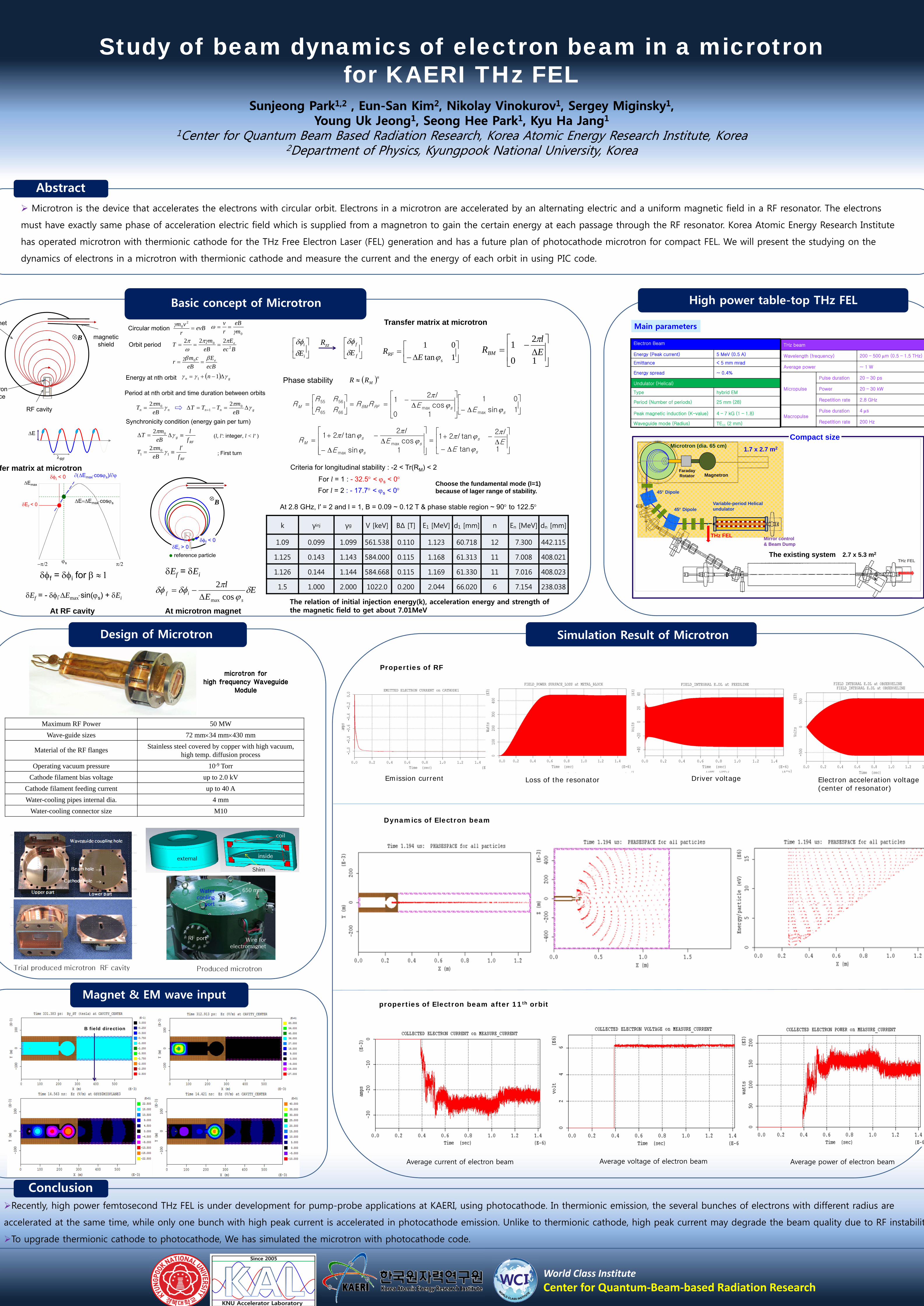
Electron Beam
Energy (Peak current) 5 MeV (0.5 A)
Emittance < 5 mm mrad
Energy spread ~ 0.4%
Undulator (Helical)
Type hybrid EM
Period (Number of periods) 25 mm (28)
Peak magnetic induction (K-value) 4 – 7 kG (1 – 1.8)
Waveguide mode (Radius) TE11 (2 mm)
High power table-top THz FEL
Microtron is the device that accelerates the electrons with circular orbit. Electrons in a microtron are accelerated by an alternating electric and a uniform magnetic field in a RF resonator. The electrons
must have exactly same phase of acceleration electric field which is supplied from a magnetron to gain the certain energy at each passage through the RF resonator. Korea Atomic Energy Research Institute
has operated microtron with thermionic cathode for the THz Free Electron Laser (FEL) generation and has a future plan of photocathode microtron for compact FEL. We will present the studying on the
dynamics of electrons in a microtron with thermionic cathode and measure the current and the energy of each orbit in using PIC code.
Basic concept of Microtron
Study of beam dynamics of electron beam in a microtron for KAERI THz FEL
Sunjeong Park1,2 , Eun-San Kim2, Nikolay Vinokurov1, Sergey Miginsky1, Young Uk Jeong1, Seong Hee Park1, Kyu Ha Jang1
1Center for Quantum Beam Based Radiation Research, Korea Atomic Energy Research Institute, Korea2Department of Physics, Kyungpook National University, Korea
THz beam
Wavelength (frequency) 200 – 500 m (0.5 – 1.5 THz)
Average power ~ 1 W
Micropulse
Pulse duration 20 – 30 ps
Power 20 – 30 kW
Repetition rate 2.8 GHz
MacropulsePulse duration 4 s
Repetition rate 200 Hz
Main parameters
Abstract
THz FEL2.7 x 5.3 m2
Variable-period Helical undulator
Mirror control& Beam Dump
Microtron (dia. 65 cm)
45 Dipole
THz FEL
45 Dipole
1.7 x 2.7 m2
MagnetronFaradayRotator
Compact size
The existing system
Simulation Result of Microtron
E
RF
net
RF cavity
magneticshield
ronce
B
evBr
vm
20
Bec
E
eB
mT e
20 222
nn eB
mT 02
gnn eB
mTTT
0
1
2
Synchronicity condition (energy gain per turn)
RFg f
l
eB
mT 02
(l, l': integer, l < l' )
RFf
l
eB
mT
1
01
2
Orbit period
Circular motion
Energy at nth orbit
Period at nth orbit and time duration between orbits
0m
eB
r
v
ecB
E
eB
cmr e
0
; First turn
gn n 11
At RF cavity
s
Emax
Ef < 0EEmaxcoss
i < 0 Emaxcoss)/
f = i for
Ef = - iEmaxsin(s) + Ei
At microtron magnet
B
reference particle
Ei > 0f < 0
Ef = Ei
EE
l
sif
cos
2
max
fer matrix at microtron
Phase stability
1sin
01
10cos
21
maxmax
6665
5655
ssRFBMM
EE
lRR
RR
RRR
1tan
2tan21
1sin
cos
2tan21
max
max
s
s
s
s
sM
EE
ll
EE
ll
R
nMRR
Criteria for longitudinal stability : -2 < Tr(RM) < 2
For l = 1 : - 32.5 < s < 0
For l = 2 : - 17.7 < s < 0Choose the fundamental mode (l=1)because of lager range of stability.
k γinj γg V [keV] BΔ [T] E1 [MeV] d1 [mm] n En [MeV] dn [mm]
1.09 0.099 1.099 561.538 0.110 1.123 60.718 12 7.300 442.115
1.125 0.143 1.143 584.000 0.115 1.168 61.313 11 7.008 408.021
1.126 0.144 1.144 584.668 0.115 1.169 61.330 11 7.016 408.023
1.5 1.000 2.000 1022.0 0.200 2.044 66.020 6 7.154 238.038
At 2.8 GHz, l′ = 2 and l = 1, B = 0.09 ~ 0.12 T & phase stable region ~ 90 to 122.5
The relation of initial injection energy(k), acceleration energy and strength of the magnetic field to get about 7.01MeV
i
i
E
f
f
ERzz
1tan
01
sRF E
R
10
21
E
lRBM
Transfer matrix at microtron
Design of Microtron
microtron for high frequency Waveguide
Module
Maximum RF Power 50 MW
Wave-guide sizes 72 mm34 mm430 mm
Material of the RF flanges Stainless steel covered by copper with high vacuum, high temp. diffusion process
Operating vacuum pressure 10-9 Torr
Cathode filament bias voltage up to 2.0 kV
Cathode filament feeding current up to 40 A
Water-cooling pipes internal dia. 4 mm
Water-cooling connector size M10
Trial produced microtron RF cavity Produced microtron
RF port 전자석용전선
650 mm
external inside
coil
Shim
RF port Wire for electromagnet
Water cooling
port
650 mm
Magnet & EM wave input
B field direction
Dynamics of Electron beam
Emission current Driver voltage Electron acceleration voltage(center of resonator)
Loss of the resonator
Properties of RF
properties of Electron beam after 11th orbit
Average current of electron beam Average voltage of electron beam Average power of electron beam
ConclusionRecently, high power femtosecond THz FEL is under development for pump-probe applications at KAERI, using photocathode. In thermionic emission, the several bunches of electrons with different radius are
accelerated at the same time, while only one bunch with high peak current is accelerated in photocathode emission. Unlike to thermionic cathode, high peak current may degrade the beam quality due to RF instabilit
To upgrade thermionic cathode to photocathode, We has simulated the microtron with photocathode code.
World Class Institute
Center for Quantum‐Beam‐based Radiation Research