study for a suspension bridge with a main span of 3700 m
TRANSCRIPT
IABSEConference–StructuralEngineering:ProvidingSolutionstoGlobalChallengesSeptember23-252015,Geneva,Switzerland
1
Studyforasuspensionbridgewithamainspanof3700m.
KeesvanIJselmuijden,AlexSwart,SanderMeijers,JorisSmits,LiesbethTromp,PeterHagenaarsRoyalHaskoningDHV,Amsterdam,theNetherlandsJacoReusinkIGWR,Rotterdam,theNetherlands
Contact:[email protected]
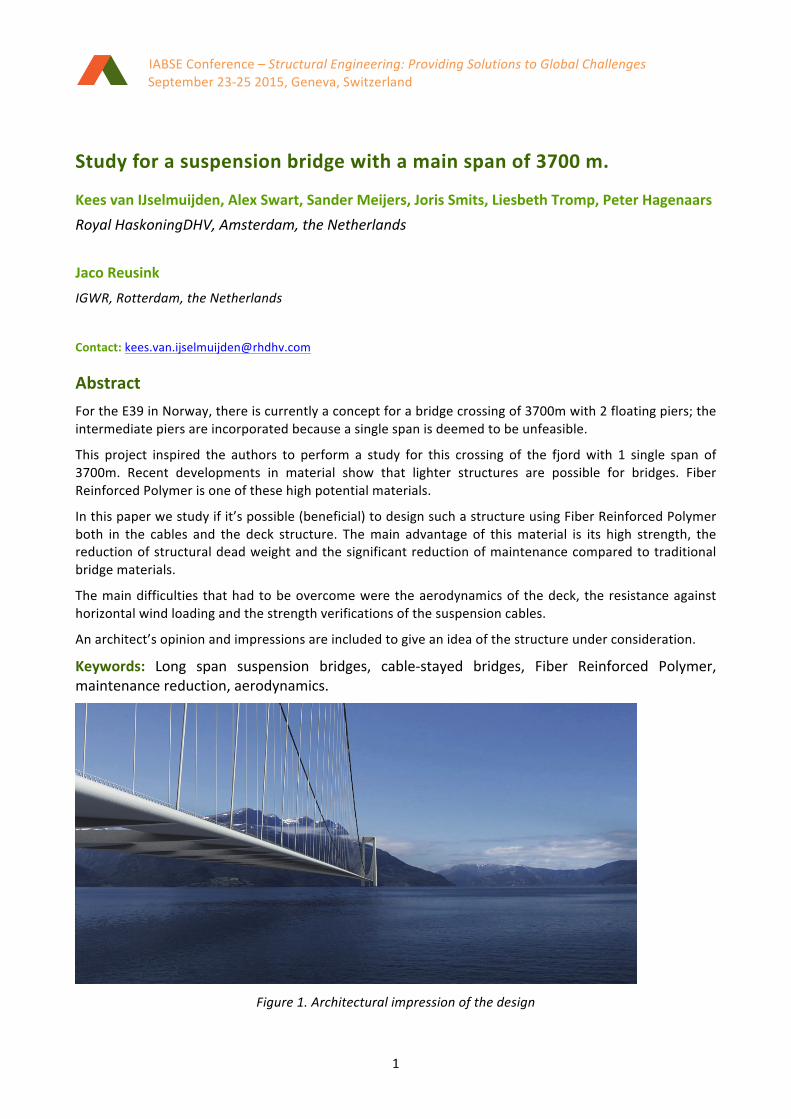
AbstractFortheE39inNorway,thereiscurrentlyaconceptforabridgecrossingof3700mwith2floatingpiers;theintermediatepiersareincorporatedbecauseasinglespanisdeemedtobeunfeasible.
This project inspired the authors to perform a study for this crossing of the fjordwith 1 single span of3700m. Recent developments in material show that lighter structures are possible for bridges. FiberReinforcedPolymerisoneofthesehighpotentialmaterials.
Inthispaperwestudyifit’spossible(beneficial)todesignsuchastructureusingFiberReinforcedPolymerboth in the cables and the deck structure. Themain advantage of thismaterial is its high strength, thereductionofstructuraldeadweightandthesignificantreductionofmaintenancecomparedtotraditionalbridgematerials.
Themaindifficultiesthathadtobeovercomeweretheaerodynamicsof thedeck, theresistanceagainsthorizontalwindloadingandthestrengthverificationsofthesuspensioncables.
Anarchitect’sopinionandimpressionsareincludedtogiveanideaofthestructureunderconsideration.
Keywords: Long span suspension bridges, cable-stayed bridges, Fiber Reinforced Polymer,maintenancereduction,aerodynamics.
Figure1.Architecturalimpressionofthedesign

IABSEConference–StructuralEngineering:ProvidingSolutionstoGlobalChallengesSeptember23-252015,Geneva,Switzerland
2
1 IntroductionThe market for extreme long-span bridges stillgrowing and because the limits of conventionalmaterials are being reached it is necessary tofocus for new options. Fiber reinforced polymer(FRP)isamaterialthatprovidessuchanoption.Ithasasignificantlyhigherultimatetensilestrengthandamuchlowerunitweightcomparedtosteel.These are necessary requirements in order toconstructabridgewithamainspanof3700mormore.TorealiseabridgewiththisspantheuseofFRPforboththesuspensioncablesaswellasthedeck structure is considered. Aramid cables areconsidered that have a maximumworking stressof σt=2500 N/mm² and a density of a mereρ=1450 kg/m³. These characteristics result in thenecessarytremendousweightreduction.
Earlier studies [1,2,3,4] have concluded that a3700m spanwith traditionalmaterialswould notbe feasible; because the self-weight of the cablewould be too heavy. The light weight of thestructure could give too much aerodynamicinstability. To overcome these difficulties weconsidered light materials and designed a deckwith a very high stiffness to overcome the lowerYoungmodulus.
Another reason to use FRP is that it has goodmaintenance properties. More maintenance isrequired over the full lifetime for corrosionprotectionofasteelbridge.FRPdoesn’tneedthesame amount of maintenance; the protection isthereforUVandaestheticsonly,theFRPwillnotcorrode.
2 AssumptionsThis is a first technical feasibility study, in whichwewanttoconcentrateonthefollowingcriteria:
1. weightofthestructure2. verticaldeflection3. horizontaldeflection4. stresses in the FRP deck and Aramid
cables5. difference between vertical and torsional
frequencies
Wemadethefollowingassumptions:
- for the stability of the deck 5% extraweightofthedeckistakenintoaccount;
- forlateralstabilityatwin-deckisapplied;- forthecharacteristicwindforce1.5kN/m2
isassumed;- Asphalt100mmon8mwidthroaddeck- Trafficload37.5kN/mperdeck- Maximum vertical and horizontal
deflectionallowedisL/200.[5]- FRPmaterials is used for thebridgedeck
andthecables.(Lateritcanbeseenwhichmaterialsmakesmoresensetouse).
- Cables with Aramid fibres (but Carbonfibresarealsopossible)areused.
- The concrete pylon is excluded from thisstudy.
The challenge is to develop a structure, whichbalances the properties of the structure and isabletoresistthetrafficandwindloadsrobustly.
3 AnalysisThe Dip-span ratio for a suspension bridge mustbebetween5and10,thecalculationofthebridgeis based on the picture below to have roundnumbers:!!= !"##
!"#= 8,22
Figure2.Span3700m,Pylon450mabovedeck.
3.1 Roaddeck
The deck only supports 2 driving lanes, sonormallyonesingledeckwouldsatisfy.However,if we look at stability, a twin deck is preferable.Weselectedadistanceof30mcentertocenter,inthelongitudinaldirectionfortheverticalcables.Inthetransversedirectionthedistancebetweenthecablesis48m.
IABSEConference–StructuralEngineering:ProvidingSolutionstoGlobalChallengesSeptember23-252015,Geneva,Switzerland
3
The cables are connected in the transversedirection with a steel cross girder. In thelongitudinaldirectionthedeckisconnectedtothissteelcross-girderthisalsosupportstheFRPdeck.
3.2 Mainroaddeck:
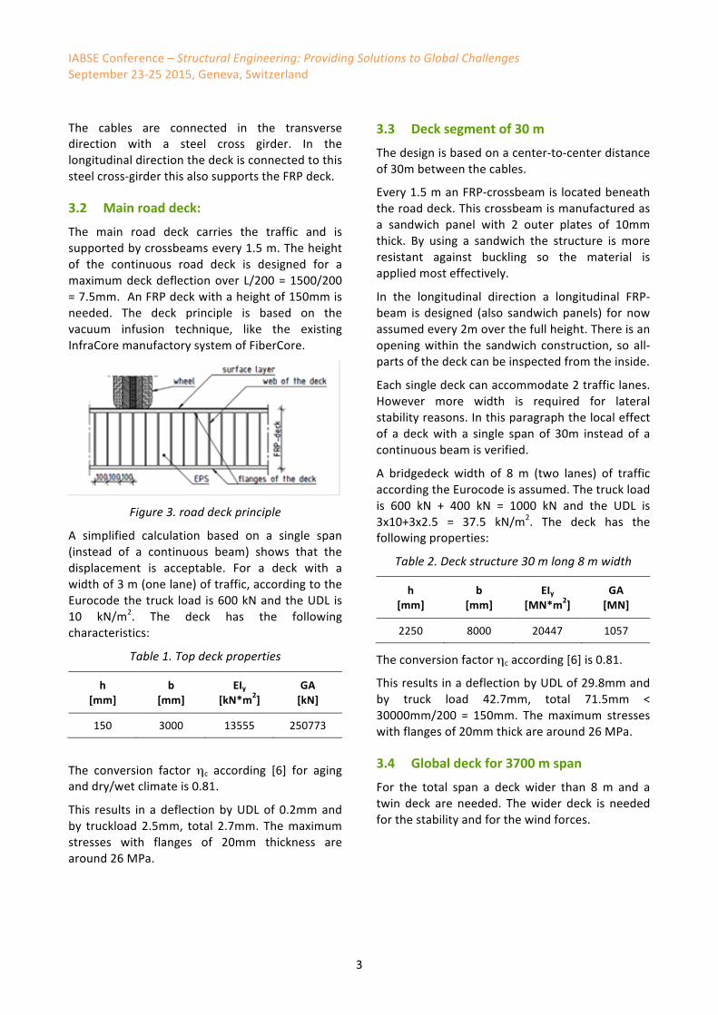
The main road deck carries the traffic and issupportedbycrossbeamsevery1.5m.Theheightof the continuous road deck is designed for amaximumdeckdeflectionoverL/200=1500/200=7.5mm.AnFRPdeckwithaheightof150mmisneeded. The deck principle is based on thevacuum infusion technique, like the existingInfraCoremanufactorysystemofFiberCore.
Figure3.roaddeckprinciple
A simplified calculation based on a single span(instead of a continuous beam) shows that thedisplacement is acceptable. For a deck with awidthof3m(onelane)oftraffic,accordingtotheEurocodethetruck load is600kNandtheUDL is10 kN/m2. The deck has the followingcharacteristics:
Table1.Topdeckproperties
h[mm]
b[mm]
EIy[kN*m2]
GA[kN]
150 3000 13555 250773
The conversion factor ηc according [6] for aginganddry/wetclimateis0.81.
This results in adeflectionbyUDLof0.2mmandby truckload2.5mm, total 2.7mm. Themaximumstresses with flanges of 20mm thickness arearound26MPa.
3.3 Decksegmentof30m
Thedesignisbasedonacenter-to-centerdistanceof30mbetweenthecables.
Every1.5manFRP-crossbeamislocatedbeneaththeroaddeck.Thiscrossbeamismanufacturedasa sandwich panel with 2 outer plates of 10mmthick. By using a sandwich the structure is moreresistant against buckling so the material isappliedmosteffectively.
In the longitudinal direction a longitudinal FRP-beam isdesigned (also sandwichpanels) fornowassumedevery2moverthefullheight.Thereisanopeningwithin the sandwich construction, so all-partsofthedeckcanbeinspectedfromtheinside.
Eachsingledeckcanaccommodate2trafficlanes.However more width is required for lateralstabilityreasons.Inthisparagraphthelocaleffectof a deckwith a single span of 30m instead of acontinuousbeamisverified.
A bridgedeck width of 8 m (two lanes) of trafficaccordingtheEurocodeisassumed.Thetruckloadis 600 kN + 400 kN = 1000 kN and the UDL is3x10+3x2.5 = 37.5 kN/m2. The deck has thefollowingproperties:
Table2.Deckstructure30mlong8mwidth
h[mm]
b[mm]
EIy[MN*m2]
GA[MN]
2250 8000 20447 1057
Theconversionfactorηcaccording[6]is0.81.
ThisresultsinadeflectionbyUDLof29.8mmandby truck load 42.7mm, total 71.5mm <30000mm/200 = 150mm. Themaximum stresseswithflangesof20mmthickarearound26MPa.
3.4 Globaldeckfor3700mspan
For the total span a deck wider than 8m and atwin deck are needed. Thewider deck is neededforthestabilityandforthewindforces.

IABSEConference–StructuralEngineering:ProvidingSolutionstoGlobalChallengesSeptember23-252015,Geneva,Switzerland
4
Figure4.Bridgedeckprinciple
At this stage in the study the structure is notoptimized; the aim of the study is only to provethat for a long span a deck with FRPmaterial ispossible. The structure (without the pylons) ismodeled in Sofistik and with the form findingmodel;thedeckmomentsanddeflectionfordeadloadsareoptimized.
IntheSofistikmodelthewiderdeckismodeledasabeam.
Figure5.Sofistikmodel
3.5 Steelcrossbeam
For the connections of the twin decks andhangers,asteelcross-beamisused.Thewidthofthecrossgirderis2mandtheheightofthegirderis 3.5m at the outside where the hang cable isconnected. The FRP deck can be placedwith theroaddeckon topof thesteel crossbeamand thebottom of the deck on a steel cantilever on thesteelcrossbeam.
Figure6.Deckprinciple
Thismeansthatthedeckisalwayssupported.Theconnection between the deck and the steelcrossbeamismadewithadhesiveandsteelbolts.
3.6 Suspensioncables
Asanalternative to steel cables,CFRP cablesarepossible for long span bridges, but these havesome disadvantages. It is not easy to anchor theCarbonFiberCablesandtheyarealsonoteasytotransport. An Aramid fiber cable based on theFibreMax principle was used for the cables. Themainissueforthesecablesisthelowerstiffness(E= 129000MPa). For long spans the deflection isthereforemorethanaCarbonfiberwiththesamediameter.Butthemainadvantageisthatitcanbeanchored based on a fixed length. The cable ismadeintheexactlengthrequired.
Thecablewillbedimensionedonstiffness ratherthanstrength;stressesinthecablesarelow.
AramidPolymer
𝐺 = 129 𝐺𝑃𝑎
𝑇𝑢 = 2760 𝑀𝑃𝑎 𝑇𝑠 = 2500 𝑀𝑃𝑎

IABSEConference–StructuralEngineering:ProvidingSolutionstoGlobalChallengesSeptember23-252015,Geneva,Switzerland
5
Figure7,Aramidcables
The cables are produced with endless windingtechnology.Thetechnologyisatotallyautomatedprocess of continuouswindingof parallel strandsof fibres around two end terminations/fittingsuntil the required cable strength or cableelongationhasbeenreached.
After the lengthhasbeenprogrammed, theEWR(endless winding robot) computer calculates theamount of fibres and the amount of loopsrequired for the specified cable. During thewinding process the EWR maintains an equaltensioninallfibreswithanaccuracyof0.1%.
Thisresultsinthehighestbreakload,loweststrainandlowestpossiblediameter.Italsoensuresthatcablesareproducedwithconstantquality.
Toavoidcreepthelengthofthecablesisadjustedduring manufacturing by compensating for thecreep.
Amongthedesigncriteriathemostcriticalare:• Ultimatestrength(breaking
strength/MBL),whichmayalsobedictatedbyapplicableregulationsorrules.
• Appliedloads(min/max)duringoperation(andfrequencyoftheseloads)
• Maximumallowableelongationunderload.
• Pinsize• Expectedlifetime.
All fibres in the cables are parallel wired, isaccordancewithsteelparallel-wiredcables.Thereisonlyelasticelongationofthefibrematerial.This
requiresno(orless)pre-tensioningwheninstallingthecables;ofcoursethecablescanbetensioned.The length of the cables is controlled within thecomputerized production process and lengthtolerances can be kept to a minimum (up to <1mm,dependingoncablelength).
Figure8.ConnectioncableonPylon
Asaresultoftheendlesswindingprocessthefinalstrength(MBL)ofthecableisachievedintheendtermination; when pulled to break a FibreMaxcablewillalwaysbreakintheendterminationinapre-designatedarea.Forthedesignofthecableitisthereforealsoimportanttoknowthepinsize.Apinsizethatistoosmallmayresultinearlyfailureofthecablewhenpulledtobreak.TheCableswillbe pinned on the pylon and therefore thedifferentcables(withatotaldiameterof2m)willspreadoutatthepylon(seefigure7and8).
For a lay-out of the cable please refer to thepicturebelow.
Figure9,Aramidcableprinciple

IABSEConference–StructuralEngineering:ProvidingSolutionstoGlobalChallengesSeptember23-252015,Geneva,Switzerland
6
3.7 Pylons
Thepylon is assumed tobe concrete. Thepylonsare placed in the water, but only in the shallowzone.
4 ResultsThe following elements of the bridge have beencheckedbasedontheSofistikanalysis.
4.1 Deckstructure
Table3.deck-structure
StructureULS
FRP-deckvertical
FRP-deckhorizontal
N-force[N]N-stress[MPa]
3681217.78 -
M[kN*m]σ[MPa]
2154914.66
1147415.83
δ[mm] 11360 18229
The total maximum stress in the structure isaround 17.78+15.83 = 33.62 MPa <<1.2%*18573MPa*0.81/ (1.15*1.5) = 129.2 MPa(UC=33.62/129.2 = 0,26). Calculation of theallowed stress is basedon the1.2% strain of theused material at the outside of the structuremultiplied with the conversion factor divided bythe material factors m1 and m2, according theupdateCUR96thatisunderconstructionnow.Thecurrent CUR96 [6] will be replaced by a newCUR96basedontheprinciplesoftheEurocode.
The vertical deflection is limited to L/200=3700m/200=18.5m.Thedisplacementof11.26mis within limits. The same holds for horizontaldeflection18.23m<18.5m.
The steel cross girder has not been designed indetail,butwithin theglobaldimensions it canbeconsideredstructurallyfeasible.
4.2 Cables
Twaron2200(Aramid)areusedinthemaincableandthehangers.
Table4.Cables
StructureULS
MaincableD=2000mm
HangcableD=300mm
N-force[kN]N-stress[MPa]
1420650452
8085114
Themaximumstress that isallowed inthisphaseis 2500MPa*0.9/(1.35*1.40)= 1190 MPa. Theunity checkof themain cable isUC=452/1190=0.38andiswithinlimits. IfthestressesarebelowaUCof0.52a lifetimeofmore than100years ispossible[7]seealsotableVI/figure10.
Figure10.LifetimeAramidcablesbasedoncontinuesbreakingloadunderconstant
temperature.
4.3 Dynamicbehavior
Natural frequencies and corresponding modeshapes have been determined for the bridgestructureonthebasisoftheSLSstressstate.
Table5.deck-structure
FrequenciesLC-
numberFrequency[Hertz]
Torsion 2008 0.085
bending 2003 0.052
ε=torsion/bending 1.62
The first translational and torsional frequenciesare 0.052 and 0.085 Hz respectively. In order toavoidflutterofthedeckthosefrequenciesshouldbe well separated. According to the modifiedSelbergformula(seee.g.Banck&Almberg[4])the

IABSEConference–StructuralEngineering:ProvidingSolutionstoGlobalChallengesSeptember23-252015,Geneva,Switzerland
7
critical wind speed is dependent on the ratio ofthe translational and torsional frequency. Withthe present ratio of 1.6 and the geometry andinertiapropertiesofthebridgeitisfoundthatthecriticalwindspeedis23m/s,whichcorrespondsto9 Beaufort and is marginally higher than theGolden Gate Bridge [8]. As at such high windspeedsturbulencetendstoruleoutflutterofthedeck; the calculated critical wind speed isconsidered as a satisfactory value for thisfeasibilitystudy.
Figure11.translationfrequency,LC2003
Figure12.torsionalfrequency,LC2008
VortexexcitationofthehangershasbeenexaminedbydeterminingtheScrutonnumberusingalogarithmicdecrementof0.03.ThecalculatedScrutonnumberof55shouldguaranteeinsensitivenesstovortexexcitation.
5 ArchitecturedesignIntheE39(1100km)moresuspensionbridgesareplanned.Afamilyofbridges,designedbyanarchitect,makesthenewE39morerecognizableandoneofakindintheworld.Forsuspensionbridgesthearchitecturaldesignhastofollowthestructuraldesign.ButFRPmaterialusedforthebridgedeckisknownforitsformabilityandallows
easierrealizationofaerodynamicandarchitecturalshapes.Anarchitectjoinedtheteamforthisbridgeandprovidedthearchitecturalvisionanddesignofthebridge.
Fromanarchitecturalviewthetruebeautyofthisbridgeliesinthedimensionsofit.Thesheersizeofthemainspanmakesthedeckappearlikeaspidersthreadacrossthewater.
Figure13.architecturalimpression
Onthisscalecarsandtrucksbecomepettyanddetailssuchasparapetsandguardrailsdissolvewithinthebignessofitall.OntheoverallscaletheproportionsoftheoutlineoftheSognefjordenBridgearemorethanslender,forwhatisa500meterpylonifthenextpylonsits3700metersawayontheothersideofthefjord?Thebridgeisdesignedwithcurveddecks,slightlytaperingtowardsthemiddlespan,andthevoidthatdividesbothcarriageways.
Themainaspectworthyofanarchitect’sattentionhoweveristhedesignofthepylons.Variouspylonconfigurations such as a single pylon in betweenthe decks, two loose pylons on either side andeven inclined pylons were soon abandoned forstructuralreasons.
Figure14.architecturalimpression
IABSEConference–StructuralEngineering:ProvidingSolutionstoGlobalChallengesSeptember23-252015,Geneva,Switzerland
8
When designing a suspension bridge this biglateralwindinducedforcesaresohighthatastiffportal of interconnected pylons is needed. Thismade us opt for an archetypical portal; straightpylons tapering slightly towards the havensinterconnected at the top by a smoothly shapedtransversebeam,adoorwayinitsbareessentials.Thesmoothenedcornersof theportal reflect theundulating landscape and bestow upon thisartifact the appearance of a peace of drift woodfoundonthebeach,bleachedbysaltandsunanddiscardedfromitsoriginalsharplines.
6 ConclusionInChapter2itisoutlinedwhatisourfocusinthisfeasibilitystudy:
1. The resulting areal weight of deck isapproximately 305 kg/m2 and is slightlylighter than other steel decks forsuspension bridges. The weight of themaincableisreducedbyaround75%.
2. Theverticaldeflectionof11.23mgivesaratioof3700/11.23=L/329>L/200[5].
3. The horizontal deflection of 18.23 mresults in a ratio of 3700/18.23 = L/203andisontarget(L/200).
4. The stresses in the FRP deck and aramidcableshavebothunitychecksbelow0.40and can be further optimized regardingthedeflections.
5. The ratio between vertical and torsionalfrequencies is 1.62. The critical windspeed is 23m/s, which corresponds to 9Beaufort.
Overall the study shows that bridges with longspans can be designed with new structuralmaterials such as FRP. The deck and the cablesfulfil their functions and the stresses are lowerthanforsteelstructures,which ispositiveforthefatigue and allows further optimisation. Thelightweight potential of FRP was less benefittedfrom,becausethelowerstiffnesswouldrequirealarger cross section, which induces larger windforces. The low maintenance for long spanstructures constructed with FRP materials is amajorbenefit.
FRP material is already a proven material forbridge decks for spans up to 30 m; larger spans
are possible but have not yet been built. Thearamid cables have been used for heavy loadedstructures.Butboththedecksandthecableshavenotyetbeenusedforthisscaleofstructures.Thispapershowsthatrealizationofthiskindofbridgeswith FRP is possible. More detailed calculationsand tests are needed to further develop andoptimisethedesign.
7 References[1] Chen W., Duan l. Bridge engineering
handbook, second edition, Fundamentals,CRCpress,TaylorandFrancisGroup;2014.
[2] LewisW.J.SmithL.AMathematicalModelfor Assessment of Material Requirementsfor Cable Supported Bridges: ImplicationsforConceptualDesign.Warwick:UniversityofWarwick;2012.
[3] KellerT.,UseofFRPinBridgeConstruction,Structuralengineeringdocuments7,Zurich:IABSE-AIPC-IVBH;2003
[4] F.Banck,O.R.Almberg,ApplicationofCFRPcables in super long span cable supportedbridges, a feasibility study,Master’s thesis,ChalmersUniversityofTechnology,2014
[5] Statenesvegvesen,SognefjordenFeasibilityStudy of Floating Bridge, 11258-03 Mainreport;2013
[6] CURCOMMISSIONC124,“Recommendation96“Fibre-ReinforcedPolymersinCivilLoad-BearingStructures”,CURGouda,2003.
[7] Teijin, Static loading of Twaron andTechnora, QBT 41303.1.1, Arnhem, TheNetherlands,2010
[8] E. Simu, R.H. Scanlan Wind effects onstructures, Fundementals and Applicationstodesign,JohnWiley&Sons,inc.NewYork,UnitedStatesofAmerica.,1996.