study control algorithms using inteco systems · study control algorithms using inteco systems...
TRANSCRIPT
Study control algorithms using INTECO systems
www.inteco.com.pl
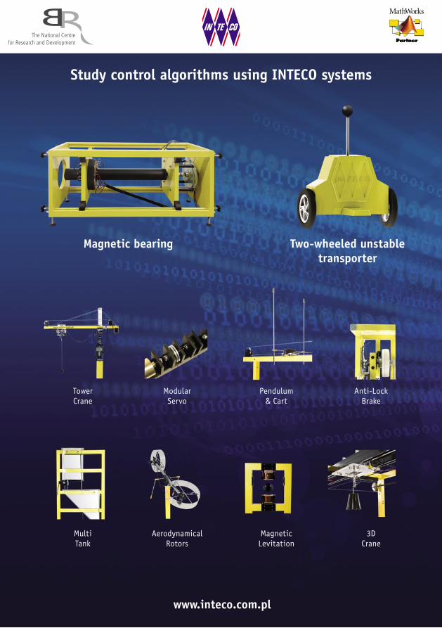
Magnetic bearing Two-wheeled unstable transporter
TowerCrane
ModularServo
Pendulum& Cart
Anti-LockBrake
MagneticLevitation
MultiTank
AerodynamicalRotors
3DCrane

INTECO provides educators and researchers with innovative, cost-effective training systems in the fields of automation, robotics, instru-mentation and process control. INTECO is the leader in the design and manufacture of mechatronic systems for the real-time control design and implementation. The company employs highly qualified staff and maintains close links with the industrial and educational world. Many product designs originate from universities. A majority of fabrication is exported. These systems are a mainspring to automatic control labo-ratories and become essential equipment for lecturers and researchers at universities and technical schools.
An incomplete list of our customers:Aland Island Aland University of Applied Sciences, MariehamnAlger E.S.L.I SARL, RouibaAustralia University of Melbourne, Victoria ♦ University of New South Wales, Sydney ♦ University of Newcastle, Callaghan ♦ Swinburne University of Technology, HawthornBelgium Université Catholique de LouvainBrasil Fundacao De Desevolvimento Da Pasquisa, Belo HorizonteBulgaria Fadata Ltd., Sofia ♦ Technical University of Sofia ♦ University of RuseCanada ABB Inc., St-Laurent ♦ Quanser Consulting Inc., Markham ♦ Simon Fraser University, Burnaby ♦ University of Alberta, Edmonton ♦ University of Sherbrooke, QuebecChina Tenfine Limited Company, Beijing ♦ Beijing Tianhua International Co., Ltd. ♦ Shanghai Passiontech Information Co.Ltd ♦ Xi’an Xidian University MechanicalCroatia University of Zagreb, ZagrebCzech Republic UNIS S. r. o., BrnoDenmark Odense Univeristy College ♦ University of Southern Denmark, SønderborgEcuador Escuela Politécnica del Ejército, QuitoEgypt German University in Cairo – GUC, New Cairo CityEstonia Tallinn University of TechnologyFinland Swedish Polytechnic, Vasa ♦ Novia Univerity of Applied Sciences, VasaFrance Ecole Centrale de Nantes ♦ Ecole des Mines de Douai ♦ Ecole Nationale Supérieure d’Ingénieurs de Limoges ♦ INRIA, Le Chesnay ♦ Multitech, Saint Cyr Sur Mer ♦ Université de Franche-Comté des Sciences et Techniques, BESANÇON ♦ Université de Picardie Julies Verne, Amiens ♦ Université de Saint-Jerome, Marseille ♦ Université de Strasbourg ♦ Université François-Rabelais Tours ♦ Université Henri Poincare Nancy ♦ Universté de Reims Champagne – Ardenne, ReimsGermany Bayerische Julius-Maximilians-Universität Wurzburg ♦ Expert Control GmbH, Herrsching ♦ Hochschule Offenburg ♦ Ilmenau University of Technology ♦ INTEL GMBH, Braunschweig ♦ Technische Universität Ilmenau ♦ Technische Universität Kaiserlautern ♦ Universität Hannover ♦ Universität Rostock ♦ Technische Universität BerlinGreece Unique Technology Ltd., ThessalonikiHong Kong The Hong Kong University of Science and Technology, KowloonHungary Budapest University of Technology and EconomicsIndia College of Engineering, Maharashtra ♦ Indian Institute of Technology Bombay ♦ University of Mumbai ♦ National Institute of Technology, TiruchirappalliIndonesia Unitronic Jaya, cv, BandungIran Electronic Afzar Azma Training & Measuring Equipments, TehranItaly Italtec S. R. L., Milano ♦ Politecnico Di Bari ♦ Università degli Studi di Pavia ♦ Università degli Studi di Salerno, Fisciano ♦ Università di Cagliari ♦ Università degli Studi del Sannio, BeneventoJapan Adtex Co, Ltd, Fujisawa City ♦ Advanced Technology and Systems Co. Ltd., Yokohama ♦ Kyoto University ♦ PID Co.Ltd., Yokohama ♦ Realtec Co., Ltd., Fujisawa CityKorea Hanyang University, Seoul ♦ Innotics Inc., South, Kyoung - San City ♦ James Trading Co., Ltd., Seoul ♦ PNP Tech, Seoul ♦ Pusan National University ♦ Seoul National University ♦ SEVIT TECH Co., Ltd., Seoul ♦ Yeungnam University, GyeongsanKuwait Gulf Advanced Trading Company, SafatLatvia University of Latvia, Riga
INTECOCompany profile and its customers
Malaysia Hitech Resources, Selangor ♦ Interpac Sdn Bhd, Selangor ♦ Realtime Innovation Sdn.Bhd., Selangor ♦ Universiti Teknologi Petronas, TronohMexico Bundes Group S.A. DECV, Mexico ♦ Centro de Investigacion y de Estuidos Avanzados del I.P.N., Mérida, Yucatán ♦ Conectividad de Culiacán Sinaloa S.A. de C.V., Sinaloa ♦ DSPPROJECTS SA DE CV, Guadalajara ♦ Instituto Politecnico Nacional, Mexico ♦ Instituto Tecnológico de Sonora ♦ Universidad Autonoma de San Luis Potosi ♦ Universidad Autónoma de Nuevo León, San Nicolás de los Garza ♦ Universidad Autónoma Metropolitana, Mexico City ♦ Universidad Nacional Autónoma de México ♦ Universidad Regiomontana Mexico, Monterrey ♦ Xochitl Cecilia Rosas Barreda, PueblaNamibia Hüster Machinetool Co. (Pty) Ltd., WindhoekNetherland Technische Universiteit EindhovenNorway Universitetet i Agder, NotoddenOman Sultan Qaboos University, Sultanate of OmanPakistan University of Engineering and Technology, TaxilaPoland AB-Micro, Warszawa ♦ AGH University of Science and Technology, Kraków ♦ Agricultural University, Kraków ♦ Automatyka, Tarnów ♦ Białystok Technical University ♦ Central Institute for Labour Protection National Research Institute, Warszawa ♦ Cracow University of Technology ♦ Delphi Automotive Systems, Kraków ♦ Eko-Pil, Straszyn ♦ Elmark Spółka Jawna Jędrzejewska, Olsztyn ♦ Falmer, Warszawa ♦ Gdańsk University of Technology ♦ InFast Sp. z o. o., Rzeszów ♦ Institute of Power Engineering, Gdańsk ♦ INTELWARE, Sandomierz ♦ Koszalin University of Technology ♦ Lublin University of Technology ♦ J.Dietl Malopolska Higher Professional School, Kraków ♦ Maritime University of Gdynia ♦ MERKAR Sp.z o.o., Poznań ♦ Military University of Technology, Warszawa ♦ ONT, Kraków ♦ Opole University of Technology ♦ Poznań University of Technology ♦ PPH WOBIT Witold Ober, Poznań ♦ PWSZ, Tarnów ♦ Rzeszów University of Technology ♦ Siemens Sp. z o. o., Warszawa ♦ Silesian University of Technology, Gliwice ♦ State Higher School in Przemyśl ♦ Technical University of Łódź ♦ University of Zielona Góra ♦ University Rzeszów ♦ Valeo, Skawina ♦ Wrocław University of Technology ♦ WSTE, Sucha Beskidzka ♦ West Pomeranian University of Technology, Szczecin ♦ ZUT “SERKO”, Kraków ♦ ZSME, ŻywiecPortugal Institute of Engineering of Porto ♦ Seccao de Sistemas Digitais e Computadores/DEEC, LisboaRomania ACOR SRL, Timisoara ♦ Lasting System SRL, Timisoara ♦ Politehnica University of Bucharest ♦ Technical University of Cluj - Napoca ♦ University OradeaSerbia Aigo BS d. o. o., Beograd ♦ Ei ELMIS Beograd ♦ Faculty of Electronic Engineering, Nis ♦ University of BelgradeSlovakia PPA ENERGO s. r. o., BratislavaSpain Robotnik Automation SLL, Valencia ♦ Universidad de Murcia ♦ Universidad Del Pais Vasco/Euskal Herriko Uniber-tsitatea, Bilbao ♦ Universidad Politécnica de Valencia ♦ Univer-sidade de Vigo ♦ Universitat de Girona ♦ Universitat Politècnica de Catalunya, BarcelonaSweden KTH School of Electrical Engineering, Stockholm ♦ Linköping University, LinkopingSwitzerland EPFL, Lausanne ♦ HSR University of Applied Sciences, RapperswilTaiwan Cho Chieh Tech. Enterprise Ltd., San Chung City ♦ Peak Instruments Corp., Banqiao CityThailand ELWE Co., Ltd., BangkokTurkey Aselsan Inc.Communications Division, Yenimahalle ♦ Festo San. Tic. A. S., Istanbul ♦ ISIK University, Istanbul ♦ Kagum Teknik Danışmanlık LTD ŞTİ, IstanbulUnited Arabian Emirates American University of Sharjah ♦ Business Communications LLC, Dubai ♦ Hatta Trading and Services, Abu Dhabi ♦ Technical Solutions International FZE, DubaiUnited Kingdom Bytronic Ltd., Sutton ♦ Feedback Instruments Ltd., Crowborough ♦ University of Reading, WhiteknightsUSA Clemson University ♦ Feedback Inc., Hillsborough ♦ Missouri University of Science and Technology, Rolla ♦ Rutgers The State University of New Jersey ♦ University of Utah, Salt Lake City
3
Autonomous real-time control of a mobile vehicle
Two-Wheeled Unstable Transporter
Two-Wheeled Unstable Transporter is an example of quite
a complex control system. It is obliged simultaneously meet
two control algorithms. The first one is a master regulator.
It is responsible to maintain the transporter in the upper
unstable equilibrium point. The second one has to follow
the predetermined trajectory of the vehicle. Linear quadratic
regulators in various forms serve in both control algorithms.
To achieve the stabilization goal we need to measure the
angle of the transporter pin deviation from the vertical posi-
tion. This angle is measured due to the combined sensors
on the single ADIS device containing an accelerometer and
a gyroscope. To stabilize the inherently unstable system it
is required the measurement of the deviation of the system
from the vertical and the measurement of angles of rotation
of both wheels on an ongoing basis. The rotation angles are
obtained from the encoders.
To actuate the transporter the wheels are driven by the PWM
signals generated by a notebook or a PC controllers. In prin-
ciple, systems manufactured by INTECO are based on the same
educational approach. At the beginning, control algorithms
are built as models, at MATLAB/Simulink or other platforms.
Fig.1. The figure on the left shows a simulation trajectory of
the transporter model.
Finally, the simulated controller is transferred to the real-
time system. Fig.2. The figure on the right illustrates the
real real-time driver. The same controller is applied that has
been previously simulated. The special “Built Send & Run on
Target” button activates the real-time control procedure. To
control in real-time several steps are required: the FPGA of
the board RT-DAC/PCI-D has to be reconfigured to communi-
cate with the ADIS device to conform its SPI protocol; the
interface has to be built in a form of S-function to get access
to measurements and control signals.
Hardware: -Autonomous unit, wireless communication with the
command input computer and trajectory visualization
output computer, battery powered
-2 DC motors equipped with gears PWM controlled
Dimensions: 440x350x600 mm
Ctrl
Sat. & Frisc. Compensation
RightRight
Left
AcceX
AcceY
AngleVel
StateObserver
State
Ctrl
Reference Reference
Reference GeneratorController
State
State
Right
Left
AcceX
AcceY
Gyro
Left
Reset
Reset
u
x
r
EncodersNormal
1
0
Build, Send & Run on Target

4
Demonstration of a gap adjustment among the shaft and bearing
Magnetic Bearing
The Software for the magnetic bearing is dedicated to two
hardware platforms: FPGA and Real-Time.
FPGA supports measurements of the following sensors:
-the position of the shaft relative to the magnetic bearings,
-the angular position of the shaft.
FPGA generates also six PWM signals to control the following
actuators:
-four coils of the bearing,
-the DC motor driving the shaft,
-the disturbance (a change in the shaft imbalance).
The imbalance measured in [µm] is shown in the figure on
the left. The initial 14 µm gap at x axis is reduced to 11 µm
gap. Similarly at y axis the initial 18.5 µm gap is reduced to
10 µm gap.
If shaft is loaded (disturbed) it can be adjusted in a few
seconds. The rotor dynamics is configurable due to the active
magnetic bearing control. In fact, the shaft is actuated
by the magnetic field generated by four control currents.
The two control currents are flowing into two coils associated
with the x-axis (see the figure in the middle). The other two
currents are flowing into two coils associated with y-axis (see
the figure on the right). The time diagrams in both figures are
scaled in volts; however these signals are proportional to the
currents of the coils.
The main control algorithm runs on the RT platform. There
are also procedures for monitoring and / or data acquisi-
tion process. Magnetic bearing control is carried out in the
MATLAB / Simulink environment using toolboxes that enable
the automatic generation of real-time tasks.
Hardware:
-frame equipped with the magnetic bearing and an ordinary
bearing, rotating shaft, DC motor and coupling
-power interface
-RT-DAC I/O internal PCIe board
Dimensions: 200x230x590 mm

5
Pum
p co
ntro
l [m
3 /s]
The Multitank System comprises a number of separate tanks
fitted with drain valves. Two of the tanks have varying cross
sections. These introduce nonlinearities into the system.
A variable speed pump is used to fill the upper tank.
The liquid outflows the tanks due to gravity. The tank valves
act as flow resistors. The area ratio of the valves is controlled
and is used to vary the outflow characteristics. Each tank
is equipped with a level sensor.
The general objective of the control is to reach and stabilize
the level in the tanks by an adjustment of the pump operation
or/and valves settings. This control problem can be solved
by a number of level control strategies ranging from PID
to adaptive and fuzzy logic.
The Multitank System is designed to operate with an external
PC-based digital controller. The computer communicates with
the level sensors, valves and pump by a dedicated I/O board
and the power interface. The I/O board is controlled by the
real-time software which operates in the MATLAB/Simulink
environment.
A dedicated library of controllers and Simulink models
support the Multitank system.
Hardware:
-3 tanks made of acrylic glass
-2 controlled valves
-3 manual valves
-pump: variable flow, driven by 12 V DC motor
-3 level sensors, piezoresistive
-interface and power supply unit
-RT-DAC I/O internal PCIe or external USB board (the PWM
control and encoder logics are stored in a XILINX chip) or
the single board RIO or a PLC
Dimesions: 700x600x1650 mm
level sensor
upper tank
level sensor
middle tank
controlled valve
lower tank
water reservoir
manual valve
pump
manual valve
Multi TankPractical verification of advanced linear and nonlinear control methods
Fuzzy Controller
The fuzzy Simulink control model and fuzzy surface generated
as the control result are shown in the figures below.
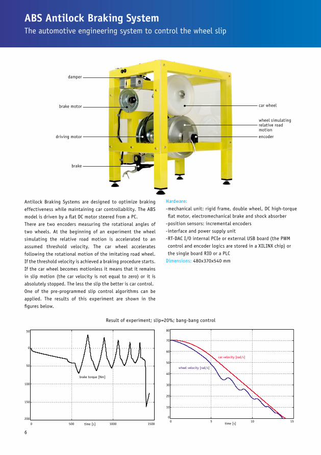
Antilock Braking Systems are designed to optimize braking
effectiveness while maintaining car controllability. The ABS
model is driven by a flat DC motor steered from a PC.
There are two encoders measuring the rotational angles of
two wheels. At the beginning of an experiment the wheel
simulating the relative road motion is accelerated to an
assumed threshold velocity. The car wheel accelerates
following the rotational motion of the imitating road wheel.
If the threshold velocity is achieved a braking procedure starts.
If the car wheel becomes motionless it means that it remains
in slip motion (the car velocity is not equal to zero) or it is
absolutely stopped. The less the slip the better is car control.
One of the pre-programmed slip control algorithms can be
applied. The results of this experiment are shown in the
figures below.
ABS Antilock Braking SystemThe automotive engineering system to control the wheel slip
brake motor car wheel
brake
wheel simulating relative road motion
driving motor encoder
damper
Result of experiment; slip=20%; bang-bang control
Hardware:
-mechanical unit: rigid frame, double wheel, DC high-torque
flat motor, electromechanical brake and shock absorber
-position sensors: incremental encoders
-interface and power supply unit
-RT-DAC I/O internal PCIe or external USB board (the PWM
control and encoder logics are stored in a XILINX chip) or
the single board RIO or a PLC
Dimensions: 480x370x540 mm
6

7
The Magnetic Levitation System (MLS) is a nonlinear, open-
loop unstable, time varying and frictionless, dynamical
system. The basic principle of MLS operation is to apply the
voltage to an electromagnet to keep a ferromagnetic sphere
levitated. Moreover, the sphere can follow a desired position
value varying in time. The coil current is measured to examine
identification and to perform control strategies. To levitate
the sphere a real-time controller is required. The equilibrium
stage of two forces (the gravitational and electromagnetic)
is maintained by the controller to keep the sphere in a desired
distance from the electromagnet. The system is fully inte-
grated with MATLAB/Simulink and operates in the real-time
in MS Windows. This feature extends MLS application and
is useful in robust controllers design. In the case of two
electromagnets the lower one can be used for an external
excitation or as a contraction unit. Alternatively, a PC
Magnetic Levitation SystemsThe frictionless electromagnetic control systems
electromagnet
position sensor
ferromagnetic sphere
position sensor on/offpower on/off
RT-DAC/PCI I/O board connector
equipped with Single Board RIO of National Instruments with
the power interface can be used. A fragment of the LabVIEW
controller is shown in the figure below.
Hardware:
-electromagnet
-ferromagnetic sphere
-position sensor
-current sensor
-power interface
-the single board RIO (the PWM control and encoder logics are
stored on the board) or RT-DAC I/O internal PCIe or external
USB board (the PWM control and encoder logics are stored
in a XILINX chip) or a PLC
Dimensions: 280x280x390 mm
8
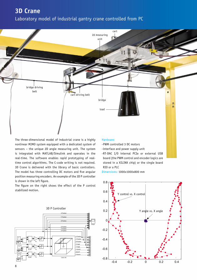
3D CraneLaboratory model of industrial gantry crane controlled from PC
3D P Controller
bridge driving
beltcart driving belt
cart
bridge
2d measuring
unit
The three-dimensional model of industrial crane is a highly
nonlinear MIMO system equipped with a dedicated system of
sensors – the unique 2D angle measuring unit. The system
is integrated with MATLAB/Simulink and operates in the
real-time. The software enables rapid prototyping of real-
time control algorithms. The C-code writing is not required.
3D Crane is delivered with the library of basic controllers.
The model has three controlling DC motors and five angular
position measuring encoders. An example of the 3D P controller
is shown in the left figure.
The figure on the right shows the effect of the P control
stabilized motion.
load
Hardware:
-PWM controlled 3 DC motors
-interface and power supply unit
-RT-DAC I/O internal PCIe or external USB
board (the PWM control and encoder logics are
stored in a XILINX chip) or the single board
RIO or a PLC
Dimensions: 1000x1000x800 mm

9
Animation in MATLAB
Pendulum angle [rad] vs. time [s] (blue line)
Control [PWM] (green line)
Pendulum & Cart Control System consists of a pole mounted
on a cart in such a way that the pole can swing freely only in
the vertical plane. The cart is driven by a DC motor. To swing
and to balance the pole the cart is pushed back and forth
on a rail of a limited length. The purpose of the inverted
pendulum control algorithm is to apply a sequence of forces
of the constrained magnitude to the cart such that the pole
starts to swing with increasing amplitude and the cart does
not override the ends of the rail. The pole is swung up to
achieve a vicinity of its upright position. Once this has been
accomplished, the controller is maintaining the pole vertical
position and is bringing the cart back to the centre of the rail.
The system operates directly in the MATLAB/Simulink envi-
ronment. The user obtains ready preprogramed experiments
in the real-time using the Real Time Windows Target to create
code with the Simulink Coder code generation software.
The user own controller can be generated in an easy way
using Simulink and library of drivers. Moreover, the nonlinear
Pendulum & Cart Control SystemThe fourth order, nonlinear and unstable real-time control system
and fourth order mathematical model of the system is
included. MATLAB/Simulink control requires RT-DAC I/O
internal PCI or external USB module (PWM control and
encoder logics are stored in a XILINX chip). Besides the
MATLAB or LabVIEW control environments all our systems
can be also controlled from any PLC, e.g. SIEMENS
SIMATIC S7-1200 PLC In the first figure below the simu-
lated snapshots of the pendulum during a rulebased
control are shown. In the second figure on the right the
time-optimal control and corresponding pendulum trajec-
tory are shown.
Hardware:
-Pendulum & Cart mechanical system driven by 12V DC
flat motor
-PWM control generated in a PC or a notebook or in a PLC
-signal conditioning interface and power supply unit
-linear bearings
Dimensions: 2200x500x850 mm
driving belt cart
pendulum
encoder
bearings

10
Two Rotor Aerodynamical SystemThe Multi Input Multi Output (MIMO) strongly cross-coupled control system
1D Pitch PID Control
Two Rotor Aerodynamical System (TRAS) is a set-up designed
for control experiments. In certain aspects its behaviour
resembles that of a helicopter. From the control point of view
it exemplifies a high order nonlinear system with significant
cross-couplings.
TRAS consists of a beam pivoted on its base in such a way that
the beam can rotate freely both in the horizontal and vertical
planes. At both ends of the beam there are rotors (the main
and tail ones) driven by DC motors.
A counterbalance arm with a weight at its end is fixed to
the beam at the pivot. The state of the beam is described by
four process variables: horizontal and vertical angles meas-
ured by encoders fitted at the pivot, and two corresponding
angular velocities. Two additional state variables are the
angular velocities of the rotors, measured by speed sensors
coupled with the driving DC motors. In a real helicopter the
aerodynamic force is controlled by changing the angle of
attack. In the laboratory set-up the angle of attack is fixed.
The aerodynamic force is controlled by varying the speed
of rotor. Significant cross couplings are observed between
actions of the rotors. Each rotor influences both position
angles. A design of stabilising controllers for TRAS is based
on decoupling.
The TRAS system has been designed to operate with an
external, PC-based controller. The control computer commu-
nicates with the position, speed sensors and motors by
a dedicated I/O board and power interface. The I/O board
is controlled by the real-time software which operates in the
MATLAB/Simulink environment. A preprogramed library of
controllers and Simulink models supports the TRAS system.
The diagram below shows the Simulink real-time 1D Pitch PID
controller.
Hardware:
-motors: 12V DC, PWM controlled
-beam position sensors: incremental encoders
-rotor velocity sensors
-RT-DAC I/O internal PCIe or external USB board (the PWM
control and encoder logics are stored in a XILINX chip) or the
single board RIO or a PLC
Dimensions: 520x520x650
tail rotor
main rotor
encoder
freely rotated beam
counter balance
dc motor with tacho

11
Tower CraneThe control goal: to track a trajectory and not to swing the load
encoders
plastic-metal slewing ring is used. The system is fully inte-
grated with MATLAB/Simulink and operates in the real-time.
A number of preprogramed control experiments are included.
They constitute a proper basis to construct own new algo-
rithms of a user. The rapid prototyping of real control algo-
rithms becomes an easy task (none C code writing is required).
There are three control drives (the DC motor equipped with
a gear) and five angular-position sensors (encoders). The jibs
rotate driven by the first powerful drive. The trolley on the jib
rail with an adjustable clearance is pushed back and forth by
the transmission belt and the second drive. The lifting load
is operated by the third drive.
The typical control goal is to track a desired three-dimen-
sional trajectory (i.e. operate the load in a desired prescribed
manner) simultaneously keeping the load at the minimal
amplitude of swinging. This effect is shown in the figure
below.
Hardware:
-3 DC motors equipped with gears PWM controlled
-interface and power supply unit
-RT-DAC I/O internal PCIe or external USB board (the PWM
control and encoder logics are stored in a XILINX chip)
or the single board RIO or a PLC
Dimensions: 1200x1200x1500 mm
The three-dimensional laboratory model of tower crane
corresponds to a modern structure of cranes that give
the best combination of height and lifting capacity.
The laboratory model is a highly nonlinear MIMO system
equipped with a dedicated system of sensors – the
unique 2D angle measuring unit. Every tower crane
consists of the jib and counter-jib (see the figure).
Both are mounted to the turntable, where the slewing
bearing and slewing machinery are located.
The counter-jib carries the counter-weight and the jib
suspends the load from the trolley. In the model the
turntable is located at the top of the tower a special
Real-time trajectories
jib
support
DC motor with a gear
trolley
slewing bearingDC drive
counter weight
tower
load
12
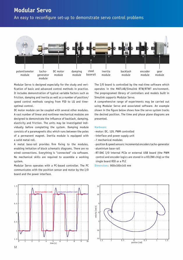
The I/O board is controlled by the real-time software which
operates in the MATLAB/Simulink RTW/RTWT environment.
The preprogramed library of controllers and models built in
Simulink supports Modular Servo.
A comprehensive range of experiments may be carried out
using Modular Servo and associated software. An example
shown in the figure below shows how the servo system tracks
the desired position. The time and phase plane diagrams are
presented.
Hardware:
-motor: DC, 12V, PWM controlled
-interface and power supply unit
-7 mechanical modules
-position & speed sensors: incremental encoders tacho-generator
-aluminium base-rail
-RT-DAC I/O internal PCIe or external USB board (the PWM
control and encoder logics are stored in a XILINX chip) or the
single board RIO or a PLC
Dimensions: 900x100x145 mm
Modular Servo is designed especially for the study and veri-
fication of basic and advanced control methods in practice.
It includes demonstration of typical variable factors such as
friction, damping and inertia as well as a number of position/
speed control methods ranging from PID to LQ and time-
optimal control.
DC motor module can be coupled with several other modules.
A vast number of linear and nonlinear mechanical modules are
designed to demonstrate the influence of backlash, damping,
elasticity and friction. The units may be investigated indi-
vidually before completing the system. Damping module
consists of a paramagnetic disc which runs between the poles
of a permanent magnet. Inertia module is equipped with
a solid metal roll.
A metal base-rail provides firm fixing to the modules,
enabling imitation of block schematic diagrams. There are no
wired connections. Everything is “connected” via software.
No mechanical skills are required to assemble a working
system.
Modular Servo operates with a PC-based controller. The PC
communicates with the position sensor and motor by the I/O
board and the power interface.
Modular ServoAn easy to reconfigure set-up to demonstrate servo control problems
potentiometer module
tacho-generator module
DC motor module
inertia module
backlash module
encoder module
gear module
damping module
steel baserail

13
This is an omnipotent functionality that conforms to a given
application. The RT-DAC family of PCI boards has A/D, D/A
converters and digital I/O lines. All the I/O functions are
realisable by hardware due to the on-board programmable
logic FPGA chip. The OMNI board equipped with an EEPROM
memory is used to store the ready-to-use or user-defined
logic. Once installed in the computer the board suits to
a number of applications that require different types and
numbers of I/O channels. It is not necessary to change the
board for a new application. Only the board’s logic is replaced.
The OMNI board behaves like an omnipotent I/O device.
RT-DAC/PCI (general) consists of 16 boards.RT-DAC/PCI-OMNI is the most potent among the general
boards in the family. The default board functions can be
replaced by a new logic structure that implements new
functions.
Specification: -16 analog inputs, 12 bits resolution, 1.8µs conversion time
per channel, input range +/-10V
-analog amplifier 1, 2, 4, 8 and 16 V/V
-4 analog outputs; 8/12-bit resolution, output
-ranges +/-10, -10-0, 0-10 V
-32 general purpose digital I/O signals, changeof-
-state (COS) interrupt from selected digital inputs
-4 PWM outputs, 8/12 bits resolution, frequency
-range from 0.15Hz to 156kHz
-4 incremental encoder inputs, 32-bit counters
-2 32-bit timers, 25ns resolution
-2 32-bit counters
-2 digital signal generators, selectable duty cycle, maximum
output frequency 20MHz
-interrupt controller, interrupt source timer, COS of digital
inputs, 2 dedicated interrupt input signals
RT-DAC USB 2.0 I/0 Module RT-DAC PCI BoardHardware reconfigurable by software. Real-time measurements and controls.
Xlinx FPGA chip
RT-DAC/USB is a portable version of the RT-DAC I/O boards.
This real-time control and measurement module trans-
fers signals between a computer and a process or a plant.
Therefore RT-DAC/USB is a perfect device to be plugged-in to
a laptop and to be connected to sensors and/or actuators of
the process constituting a portable control and measurement
stand.
FPGA technology:Reconfigurability of the digital I/O according to user
requirements
Software: -Compatible with MATLAB/Simulink
-RTCON (if MATLAB/Simulink are applied)
-RT-DAC/USB may operate directly from MS Excel sheets
-Affected OS: MS Windows
Digital USB module: -26 digital I/O signals
-4 PWM channels: 8/12 bits resolution (4 DO shared with
4 digital I/Os)
-digital generators: 1 channel, dedicated trigger and gating
signals (1 DO and 2 DI shared with 3 DI/O)
-encoders: 4 channels, optional index signal, defined active
level of the index signal (12 DI shared with 12 DI/O)
Analog USB module:
-ADC: 12 bits, +/-10V, 16 channels software programmable
gains: 1, 2, 4, 8, 16 Noise (input grounded at connector) for
gain = 16: 1.0 LSB
-Throughput: 100 kSample/sec (data acquisition mode),
1 kSample/sec (close-loop control mode)
-DAC: 12 bits, 4 channels.

14
Digital RT-DAC PCI Express BoardSimilar in operation to the RT-DAC board but for the PCI Express bus
PCI Express includes the freely reconfigurable FPGA chip of
a flexible functionality. Board functions implemented in the
hardware can be adjusted to the specific requirements of the
target application. Moreover, the board hardware configura-
tion can be changed repeatedly in a programing way.
A unique feature of the board is the ability to configure the
FPGA for direct hardware implementation of certain portions
of control algorithms, which typically are implemented by
a software way. Reliability, speed and high accuracy of the
durations of time intervals – a perfect jitter - are provided.
The period of the most rapid samples can be several tens
nanoseconds!
Xlinx FPGA chip
The architecture of measuring and control boards uses the PCI
Express bridges. They are connected from one side to the PCI
Express bus on the other side offer a local bus. The last one
is connected to the reconfigurable FPGA devoted to input /
output functions of the board.
The digital board has signal conditioning modules in the form
of the card with galvanic isolation circuits to be imposed
on the board. Dedicated board configurations often contain
common combinations of channels input / output: digital
inputs and outputs with an optional interrupt generation
“change of state interrupt”, incremental quadrature encoders
with the index, PWM wave generators, counters, frequency-
meters and chronometers.

15
National Instruments
Single or Compact Board RIO
SIEMENS PLC
INTECO USB 2.0 I/O Module
Or RT-DAC PCIe Board
www.inteco.com.pl
We provide three hardware and software options:MATLAB, LabVIEW, and any PLC, e.g. a SIEMENS PLC

Real-time control in MATLAB and Simulink, alternatively LabVIEW alternatively any PLC software, e.g. TIA PORTAL.Installation Manual, User’s Manual (rich in pre-programmed experiments).A PC with the PCIe I/O board from INTECO or a laptop with the external USB 2.0 I/Omodule from INTECO, alternatively a PC with the Single or Compact Board RIOfrom National Instruments, alternatively any PLC, e.g. SIEMENS PLC.
Software
ManualsControllers
INTECO Sp. z o. o. Katowicka 36, 31-351 Krakow, Polandtel./fax: +48 12 430 49 61 e-mail: [email protected]