study and fabrication of gas turbine engine high...
TRANSCRIPT

1
UNIVERSITY OF PETROLEUM AND ENERGY STUDIES
Study and Fabrication of a Gas Turbine Engine: High Bypass
Minor Project by Aakanksha Dhar (R180208048)
Samaksh Behl (R180208033) Yachna Gola (R180208056)
Project Supervisor: Prof. Dr. Ugur Guven Department : ASE Programme : B.Tech Aerospace Engineering

2
FOREWORD
I would like to express my deep appreciation and thanks for my advisor. This work is supported by Prof. Dr. Ugur Guven.
March 2011

3
TABLE OF CONTENTS
Page
TABLE OF CONTENTS .......................................................................................... 3 LIST OF FIGURES ................................................................................................... 6 SUMMARY ................................................................................................................ 7 CHAPTER ONE ........................................................................................................ 8 1. INTRODUCTION .................................................................................................. 8 2.ENGINE...................................................................................................................9
2.1 External Combustion Engine ............................................................................. 9 2.2 Internal Combustion Engine .............................................................................. 9 2.3 Gas Turbine Engine .......................................................................................... 10
2.3.1 Compressor ............................................................................................... 10 2.3.2 Combustion Chamber ............................................................................... 10 2.3.3 Turbine ...................................................................................................... 10
3.TURBOFAN ENGINE..........................................................................................10 3.1 Low Bypass Turbofan Engine .......................................................................... 11
3.2 High Bypass Turbofan Engine ......................................................................... 11
3.3 Advantages of a Turbofan Engine .................................................................... 11
3.4 Disadvantages of a Turbofan Engine ............................................................... 11
3.5 Design of a Turbofan Engine ........................................................................... 11 3.5.1 Inlet ........................................................................................................... 12 3.5.2 Compressor ............................................................................................... 12
3.5.2.1 Centrifugal Compressor......................................................................13 3.5.2.2 Axial Compressor...............................................................................13
3.5.3 Burner ....................................................................................................... 13 3.5.3.1 Annular type Burner...........................................................................14 3.5.3.2 Can type Burner..................................................................................14 3.5.3.3 Can-Annular type Burner ...................................................................14
3.5.4 Turbine ...................................................................................................... 14 3.5.5 Nozzle ....................................................................................................... 15
3.5.5.1 Convergent Nozzle.............................................................................15 3.5.5.2 Convergent-Divergent Nozzle............................................................15
3.6 Working of a Turbofan Engine ........................................................................ 15
3.7 Thermodynamics of a Turbofan Engine .......................................................... 16
3.7.1 Inlet ........................................................................................................... 16 3.7.2 Compressor ............................................................................................... 17 3.7.3 Combustor ................................................................................................. 18 3.7.4 Turbine ...................................................................................................... 18 3.7.5 Nozzle ....................................................................................................... 18
3.8 Thrust Produced by a Turbofan Engine ........................................................... 19 4. CONCLUSION .................................................................................................... 19
4
CHAPTER TWO ..................................................................................................... 21 1. INTRODUCTION ................................................................................................ 21 2. EQUATION GOVERNING THRUST OF A TURBOFANENGINE... ...........22
2.1 Data Assumed in the Program .......................................................................... 22 2.1.1 Data for High Bypass Turbofan Engine .................................................... 23 2.1.2 Data for Low Bypass Turbofan Engine .................................................... 23
2.2 Programs ........................................................................................................... 23 2.2.1 Program Computing Thrust for High Bypass Turbofan Engine ............... 23 2.2.2 Program Computing Thrust for Low Bypass Turbofan Engine ................ 24
2.3 Results .............................................................................................................. 25 2.3.1 High Bypass Turbofan Engine .................................................................. 25 2.3.2 Low Bypass Turbofan Engine ................................................................... 26
2.4 Conclusions ...................................................................................................... 27 3.BREGUET'S EQUATION GOVERNING THE RANGE OF JET ENG INE.27
3.1 Data Assumed in the Program .......................................................................... 28 3.1.1 Case 1: k=2................................................................................................ 28 3.1.2 Case 2: k=2.7............................................................................................. 28
3.2 Programs ........................................................................................................... 28 3.2.1 Program for k=2 ....................................................................................... 29 3.2.2 Program for k=2.7 ..................................................................................... 29
3.3 Results .............................................................................................................. 30 3.3.1 For k=2 ...................................................................................................... 30 3.3.2 For k=2.7 ................................................................................................... 31
3.4 Conclusions ...................................................................................................... 32 4.BREGUET'S EQUATION FOR EFFECT OF TSFC ON RANGE ................33
4.1 Data Assumed in the Program .......................................................................... 33 4.2 Programs ........................................................................................................... 34 4.3 Results .............................................................................................................. 34 4.4 Conclusions ...................................................................................................... 35
5.EQUATION FOR ENDURANCE OF TURBOFAN ENGINE ........................35 5.1 Data Assumed in the Program .......................................................................... 36 5.2 Program ............................................................................................................ 36 5.3 Results .............................................................................................................. 37 5.4 Conclusions ...................................................................................................... 38
CHAPTER THREE ................................................................................................. 39 1. INTRODUCTION ................................................................................................ 39
1.1 Gambit .............................................................................................................. 39 1.2 Fluent ................................................................................................................ 39
2. DEVELOPMENT OF GAMBIT MODEL ........................................................ 40
2.1 Development of Low Bypass Turbofan Engine Model.................................... 40
2.1 Development of High Bypass Turbofan Engine Model ................................... 48
3. ANALYSIS OF TURBOFAN ENGINE IN FLUENT .......... ............................ 49
3.1 Conclusions Drawn from Pressure Contours ................................................... 53
3.2 Conclusions Drawn from Velocity Contours ................................................... 56
3.3 Conclusions Drawn from Temperature Contours ............................................ 58

5
CHAPTER FOUR .................................................................................................... 59 1. INTRODUCTION ................................................................................................ 59 1.1 Material used ...................................................................................................... 59 2. VARIOUS PARTS OF SCALE MODEL .......................................................... 60
2.1 Shaft ................................................................................................................. 60 2.2 Compressor ...................................................................................................... 60 2.3 Combustor Chamber ........................................................................................ 61 2.4 Turbine ............................................................................................................. 61 2.5 Nozzle .............................................................................................................. 62 2.6 Fan .................................................................................................................... 62 2.7 Cowling ............................................................................................................ 62
CONCLUSIONS ...................................................................................................... 63 REFERENCES ......................................................................................................... 66

6
LIST OF FIGURES
Page
CHAPTER ONE . ........................................................................................................ 7 Figure 2.1 : A Simple Gas Turbine Engine. ................................................................ 8 Figure 3.1 : High Bypass Turbofan Engine .............................................................. 10 Figure 3.2 : Low Turbofan Engine ............................................................................ 10 Figure 5.1 : A Simple Design of a Turbofan Engine ................................................ 11 CHAPTER TWO . ..................................................................................................... 21 Figure 2.1 : Matlab Program for Computing Thrust. ................................................ 25 Figure 2.2 : Thrust v/s Velocity for High Bypass Turbofan Engine. ........................ 25 Figure 2.3 : Matlab Program for Thrust Calculation. ................................................ 26 Figure 2.4 : Thrust v/s Velocity for Low Bypass Turbofan Engine. ......................... 26 Figure 3.1 : Matlab Program for Breguet’s Equation of Range. ............................... 30 Figure 3.2 : Range v/s Airspeed for k=2. .................................................................. 30 Figure 3.3 : Matlab Program for Breguet’s Equation of Range. ............................... 31 Figure 3.4 : Range v/s Airspeed for k=2.7. ............................................................... 31 Figure 3.5 : Range v/s Airspeed. ............................................................................... 32 Figure 4.1 : Matlab Program for Breguet’s Equation of Range v/s TSFC. ............... 34 Figure 4.2 : Range v/s TSFC. .................................................................................... 35 Figure 5.1 : Matlab Program for Endurance Equation. ............................................. 37 Figure 5.2 : Endurance v/s TSFC. ............................................................................. 37 CHAPTER THREE . ................................................................................................ 39 Figure 2.1 : Step 1 and Step 2. .................................................................................. 41 Figure 2.2 : Step 3. .................................................................................................... 42 Figure 2.3 : Step 4. .................................................................................................... 43 Figure 2.4 : Step 5. .................................................................................................... 44 Figure 2.5 : Step 6. .................................................................................................... 45 Figure 2.6 : Step 7.and Step 8 ................................................................................... 46 Figure 2.7 : Step 9 and Step 10. ................................................................................ 47 Figure 2.8 : Step 11 ................................................................................................... 48 Figure 3.1 : Grid for Low Bypass Turbofan Engine . ............................................... 49 Figure 3.2 : Grid for High Bypass Turbofan Engine. ............................................... 50 Figure 3.3 : Error Residual Plot for Low Bypass Turbofan Engine. ......................... 51 Figure 3.4 : Error Residual Plot for High Bypass Turbofan Engine ......................... 51 Figure 3.5 : Total Pressure Contours for Low Bypass Turbofan Engine .................. 52 Figure 3.6 : Total Pressure Contours for High Bypass Turbofan Engine ................. 52 Figure 3.7 : Inlet Velocity Contours for Low Bypass Turbofan Engine. .................. 54 Figure 3.8 : Inlet Velocity Contours for High Bypass Turbofan Engine. ................. 54 Figure 3.9 : Outlet Velocity Contours for Low Bypass Turbofan Engine ................ 55 Figure 3.10 : Outlet Velocity Contours for High Bypass Turbofan Engine ............. 55 Figure 3.11 : Temperature Contours for Low Bypass Turbofan Engine. ................. 57 Figure 3.12 : Temperature Contours for High Bypass Turbofan Engine .................. 57

7
CHAPTER FOUR. ................................................................................................... 59 Figure 1.1 : Shaft of Scale Model. ............................................................................ 60 Figure 1.2 : Compressor Blade of Scale Model. ....................................................... 61 Figure 1.3 : Fan Blade of Scale Model. .................................................................... 62 Figure 1.4 : Cowling of the Model ............................................................................ 63

8
Study and Fabrication of Scale Model of a Gas Turbine Engine
SUMMARY
A turbofan engine is an internal combustion gas turbine engine. The turbofan engine
differs from the other gas turbine engines because of the presence of a fan mounted
inside the casing.
In the following chapters, various parameters governing the performance of a
Turbofan Engine which are primarly comprised of Range, Endurance, Thrust
Specific Fuel Consumption, Propulsive Efficiency, Fan Efficiency, Shaft Horse
Power, etc have been discussed. The equations used are the emperical relations
which help us compute the above parameters by means of programming.The
programs are written in Matlab 7.0 and the various graphs are plotted using plot tool
in the Matlab 7.0.
Furhter, flow through the engine has been analysed using CFD tools i.e GAMBIT
and FLUENT. Performance of low bypass and high bypass turbofan engines have
been compared using the same.

9
CHAPTER ONE
INTRODUCTION
The Gas Turbine Engines are used in almost every aircraft nowadays. They are
basically internal combustion engines which provide essential thrust to move, fly the
aircraft efficiently and safely.
1.1 Purpose of the Thesis
The purpose of this thesis is to analyse the working of the Turbofan engine and to
study the flow inside the engine.
1.2 Background
Following developments in Turbofan engine have helped to achieve great fuel
efficient and less noisy engines. The new engines have great power and thrust. The
engines made nowadays are very compact in size and simple in their overall layout.

10
Figure 2.1 : A Simple Gas Turbine Cycle
2. ENGINE
Engine is a machine which is used to convert energy into useful mechanical motion.
The engines which convert heat energy into mechanical motion are called as heat
engines. Combustion engines (heat engines) are driven by the heat generated by a
combustion process.
2.1 External Combustion Engine
In this type of engine, the working fluid is heated by combustion of an external
source through the engine wall which acts as a heat exchanger.
2.2 Internal Combustion Engine
In this type of engine, the combustion of a fuel with an oxidizer (usually air) takes
place inside a combustion chamber.

11
2.3 Gas Turbine Engine
Most of the gas turbine engines are internal combustion engines. A gas turbine
engine extracts energy from the flow of a combustion gas. There are three main
components of a simple a gas turbine engine, namely a compressor, a turbine and a
combustion chamber.
2.3.1 Compressor
A compressor compresses incoming air to high pressure. The pressure rise is
achieved by converting the high kinetic energy of incoming air into pressure energy.
2.3.2 Combustion Chamber
Inside a combustion chamber, the fuel mixed with oxidiser (air) is burned to produce
high- pressure, high-velocity gas.
2.3.3 Turbine
A turbine extracts the energy from the high-pressure, high-velocity gas which is
flowing through the combustion chamber.
3. TURBOFAN ENGINE
A turbofan engine, is a gas turbine engine that uses a Gas Generator Core,
comprising of a compressor, a combustor and a turbine to generate kinetic energy in
the exhaust by means of converting the internal energy in the fuel into kinetic energy.
Turbofans are generally more efficient than turbojets at subsonic speeds. This can be
understood from the following:

12
A turbofan engine comprises of a fan, in addition to the gas generator core and
nozzle. The fan, just like the compressor is powered by the turbine section of the
engine. In a turbofan engine, the exhaust through the nozzle not only comprises of
the gas flow through the engine core, but also the flow accelerated by the fan by
passing the gas generator core of the engine. So, a turbofan engine gets some of its
thrust from the core and some of the thrust from the fan. The by passed flow is at
lower velocities than the flow through the gas generator core. But owing to its higher
mass, the thrust produced by the fan is more efficient than the thrust produced by the
core. Hence, turbofan engine is more efficient than turbojets at subsonic speeds.
The ratio of the air that goes around the engine to the air the air that goes through the
engine core is called BYPASS RATIO.
Fig 3.1: A Low Bypass Turbofan Engine
3.1 Low Bypass Turbofan Engine
Low bypass turbofan engines usually have a bypass ratio of 2:1 or even less than
that. The bypass flow and the core flow can exit either through the same nozzle or
separate nozzles.
Generally, low bypass turbofan engines make use of a mixed exhaust nozzle i.e. the
bypass flow and the core flow exit from the same nozzle.
Fig 3.2: A High Bypass Turbofan Engine

13
3.2 High Bypass Turbofan Engine
High bypass turbofan engines have a bypass ratio of the order of 5:1 or 6:1 which
implies, they have larger bypass ratios. Since a large mass of air is accelerated by a
fan in high bypass turbofan engines, these are much more fuel efficient and produce
much more thrust as compared to a low bypass turbofan engine or a turbojet engine.
3.3 Advantages of a Turbofan Engine
• Since a fan is used, more amount of air is sucked into the engine providing
more thrust
• The fan is enclosed by the cowling and is thus protected and its aerodynamics
can be easily controlled
• The extra amount of air, which bypasses the core of the engine, produces
extra thrust than any the turboprop or turbojet engine.
• Due to presence of fan, the fuel consumption is increased only a little , the
turbofan produces more thrust for same amount of fuel and is thus fuel
efficient.
3.4 Disadvantages of a Turbofan Engine
• It is the most efficient at subsonic speeds only
• It has a greater complexity due to addition of ducts and multiple shafts
• The engine diameter is increased
3.5 Design of a Turbofan Engine
A turbofan engine essentially consists of an inlet, a fan, a compressor, a combustion
chamber (burner or combustor), a turbine, and a nozzle.

14
3.5.1 Inlet
An inlet is used in all turbine engines for directing the free stream air into the engine.
The inlets may be of various shapes and sizes. Depending upon the speed of the
aircraft, these are classified as:
• Subsonic inlets
• Supersonic inlets
• Hypersonic inlets
The inlet efficiency has a strong effect on the net thrust produced by the aircraft
engine, both at low speeds and high speeds. Hence, an inlet must operate efficiently
over the entire flight envelope of the aircraft.
Fig 5.1: A Simple Design of Turbofan Engine
3.5.2 Compressor
A compressor is a part of the engine which increases the pressure of the incoming air
before it enters the combustion chamber.

15
3.5.2.1 Centrifugal Compressor
A centrifugal compressor turns the flow through the compressor perpendicular to the
axis of rotation i.e. the air enters axially and is delivered radially. It produces a high
pressure ratio of 4:1 or 5:1 in a single stage.
3.5.2.2 Axial Compressor
In an axial compressor, the air enters axially and delivers axially. It is much more
fuel efficient than a centrifugal compressor. Moreover, it gives the turbofan engine a
long, slim and streamlined appearance. The engine diameter is reduced which results
in much low aircraft drag. A multistage axial compressor can develop a pressure
ratio as high as 6:1 or more. The air handled by this is more than that handled by a
centrifugal compressor of the same diameter. The thrust produced per unit diameter
is more. It also ensures 6% to 8% less specific fuel consumption.
A compressor consists of rotating parts called rotors and stationary parts called
stators. Rotors are attached to the central shaft rotating at high speed, while the
stators remain fixed. Further the rotors may be drum type or disc type rotor. The
compressor blades are airfoil shaped and produce pressure variation much like the
airfoil of a spinning propeller. A stator increases the pressure and keeps the flow
from spiraling around the axis by bringing the flow back parallel to the axis. The
rotors and the stators are placed in alternating sequence such that the compressor is
composed of several rows of airfoil cascades. One set of a stator and a rotor is called
a stage. The number of stages used in a compressor depends upon the pressure ratio
required.
3.5.3 Burner
In combustion chamber or burner, the fuel is mixed with high pressure air and
burned. These must be designed to ensure stable combustion of the fuel injected and
optimum fuel utilization within the limited space available and over a large range of

16
air to fuel ratios. The design of the combustion chamber depends upon the
application and requirements in each case.
3.5.3.1 Annular type burner
The liner of the annular combustion chamber consists of a continuous, circular, inner
and outer shroud around the outside of the compressor drive shaft. The inner is often
called a “burner basket” because of its shape and the many holes that allow cooling
air inside. In this type of chamber, fuel is introduced through a series of nozzles. The
configuration ensures better mixing of air-fuel, better use of available space and
uniform heat distribution.
3.5.3.2 Can type burner
Can type combustion chambers are particularly suitable for engines with centrifugal-
flow compressors as the airflow is already divided by the compressor outlet diffusers.
The separate flame tubes are all interconnected. The entire combustion system
consists of 8 to 12 cans that are arranged around the engine. The disadvantage of this
design comprises of the unfavorable inflow/outflow ratios and the associated large
size. Ignition problems may also occur at high altitudes. The advantages include low
development cost and good accessibility for servicing.
3.5.3.2 Can-Annular type burner
It is a combination of can type and annular type combustion chamber. In this type of
combustion chamber, all flame tubes have a common secondary air duct. The
aerodynamic properties of this type are inferior to those of annular type combustion
chamber. These are suitable for large engines (for mechanical reasons) and the ones
with high pressure ratios. Development costs are lower and volume smaller than with
a can type combustion chamber.
3.5.4 Turbine
A turbine extracts energy from the hot flow and turns the compressor. The high
pressure and temperature gases expand through the turbine to provide enough power
output from the turbine. The turbine is directly connected to the compressor and all
the power developed by the turbine is absorbed by the compressor and its auxiliaries.

17
A turbine, just like a compressor consists of rotors and stators. The stators prevent
the flow from spiraling. Depending on the engine type, the turbine may be multi
staged. A single turbine stage can be used to drive multiple compressor stages
effectively. Turbofan engines generally employ a separate turbine and shaft to power
the fan and the gear box respectively. This arrangement is called two spool engines.
3.5.5 Nozzle
After the gases leave the turbine they expand further in the exhaust nozzle and are
ejected into the atmosphere with a velocity greater than the flight velocity, thereby
producing thrust for propulsion. There are two types of nozzles:
3.5.5.1 Convergent nozzle
These nozzles have a fixed geometry.
The convergent nozzle is a simple convergent duct. When the nozzle pressure ratio
(pe /po) is low (less than about 4), the convergent nozzle is used. The convergent
nozzle has generally been used in engines for subsonic aircrafts.
pe = pressure at exit
po = pressure at entry
3.5.5.2 Convergent – Divergent nozzle
These are used in turbofan engines. It has both Convergent duct and divergent duct.
Most convergent-divergent nozzles used in aircrafts are not simple ducts. They
incorporate variable geometry and other aerodynamic features. It is used when the
nozzle pressure ratio is high (greater than about 6). Variable geometry nozzles are
also more efficient over a wider range of airflow, than fixed geometry nozzles. This
is because the flow is first converged to a minimum area or throat and then expanded
through the divergent section to the exit.
3.6 Working of a Turbofan Engine
In a turbofan engine the air is sucked in by the fan into the inlet. Some of the air
enters the core of the engine while the rest bypasses .The air that flows into the core

18
of the engine, enters the compressor first. In the compressor, kinetic energy of the air
is converted into raise in the pressure energy. In case of a centrifugal compressor, air
is accelerated to the impeller. In the impeller the kinetic energy and static pressure of
the air are raised. The diffuser then converts the high kinetic energy into static
pressure. While in the case of axial compressor the rotating blades impart kinetic
energy to the air which is converted into static pressure. The stators help to recover
the kinetic energy of the fluid as well as direct the flow. The temperature of the air is
raised in the combustion chamber. The four steps involved in a burner are:
• Formation of the air fuel mixture
• Ignition
• Flame propagation
• Cooling of combustion products.
The uniform mixing of air and fuel mixture is important for complete and stable
combustion. The air leaving the combustion chamber must be at a temperature which
the turbine blades can tolerate. To ensure this, a primary amount of air is admitted for
a stable combustion and a secondary amount of air at a lower temperature is
introduced to cool down the gases. The cooled air is expanded in the turbine and thus
power is produced. This power is used to drive the fan through the shaft. The exhaust
gases then enter the nozzle. The velocity of the gases is increased as it passes out of
the nozzle. The thrust obtained is highest when the exit pressure equals the
atmospheric pressure. The air that bypasses (just passes through the fan) flows all
around the core of the engine and finally leaves through the nozzle at a velocity
higher than the initial velocity. So a turbofan engine gets some of it thrust from the
core engine and some of it from the fan. The ratio of the air that bypasses to the air
that goes into the core of the engine is called the bypass ratio of the engine.
3.7 Thermodynamics of a Turbofan Engine
3.7.1 Inlet
The inlet does no thermodynamic work and the total temperature through out the
nozzle remains constant. The total pressure changes across an inlet. The pressure
recovery which is defined as the recovery of free stream pressure is given by the ratio
of pressure at the inlet exit to the free stream pressure.

19
Pressure Recovery = ���� (7.1)
Where p2 is the pressure at the inlet exit and p0 is the free stream pressure.
3.7.2 Compressor
The air is compressed in the turbine. Since there is no addition or reduction of heat in
the system and there are no frictional losses, the process is isentropic. Thus the
pressure is raised isentropically in the compressor. Higher the value of compressor
pressure ratio higher is the efficiency of the compressor. The relation between the
temperatures and the pressures at the entrance and exit of the compressor are as
follows:
�� ��� = � �� �� �� � �
(7.2)
where µ is the ratio of specific heats , p3 and t3 are the pressure and temperature at
the exit of compressor while p2 and t2 are the pressure and temperature at the
entrance of the compressor.
The work done by the compressor is equal to the change in enthalpy per unit mass of
flow from the entrance to the exit.
�� = ℎ� − ℎ� (7.3)
Where CW is the compressor work, h3 and h2 are the specific enthalpies at the exit
and the entrance.
The enthalpy is related to the temperature as follows
ℎ = �� × � (7.4)
Thus,
�� = �� × ��� − ��� (7.5)
The compressor pressure ratio (CPR) is always greater than 1 and the value of µ is
also equal to 1.4 for air. Thus the temperature ratio is greater than 1. We can
therefore conclude that air heats up as it passes through the compressor.

20
3.7.3 Combustor
The air is mixed with fuel and combustion takes place inside the combustion
chamber. The burning takes place at a higher pressure than the free stream pressure
because of the pressure raise that takes place in the compressor. The pressure in the
burner remains constant decreasing only by 1 or 2 percent.
Since heat is produced inside the combustor, energy equation is applied to determine
the temperature change.
�1 + �� × ℎ� = ℎ� + � × � × � (7.6)
Where, f is the fuel to air mass flow ratio , h3 and h4 are enthalpies at the exit and
entrance of the burner, ƞ is an efficiency factor considered due to losses during the
burning process , and Q refers to the heat released.
3.7.4 Turbine
The air is expanded isentropically in the turbine. Thus, the turbine pressure ratio is
always less than 1. Since the process is isentropic the relation between temperature
and pressure is given by
� �� = �� ��� �� �� � �
(7.7)
Where, p5 and t5 are the pressure and temperature at exit of the turbine, p4 and t4 are
the pressure and temperature at the entrance of the turbine. The turbine work is as
follows
�� = �� × ��� − ��� (7.8)
The turbine blade must be made of a special material which can tolerate the high
temperatures.
3.7.5 Nozzle
The temperature and the pressure remain constant through out the nozzle although
the velocity increases as air leaves the nozzle.

21
3.8 THRUST PRODUCED BY A TURBOFAN ENGINE
Thrust is a force produced by accelerating a mass of gas according to Newton’s third
law of motion. Also force equals the rate of change of momentum according to
Newton’s second law of motion. A gas is accelerated to rear through the engine due
to which the aircraft is accelerated in opposite direction.
Thus the thrust equation is as follows
= !�"� − !�"� ��� − ���� � (8.1)
In a turbofan engine some of the air bypasses the engine core and thus the thrust
equation is given as follows:
Thrust = thrust of fan + thrust of the core
= #!$ %"% − !$ %"&' + �!$ ("( − !$ )"&� (8.2)
Where,
!$ f = mass flow through fan
!$ c =mass flow through core
4. CONCLUSION
A higher bypass ratio gives a low (actual) exhaust speed. As a result, the thrust
specific fuel consumption is reduced. A lower bypass ratio gives high exhaust speed,
which is used to sustain supersonic speeds. Thus, one can conclude that a high
bypass turbofan engine gives lower thrust specific fuel consumption.
A high bypass turbofan engine is used at subsonic speeds because of low exhaust
speed it produces.
Turbofan engines gain better performance capabilities and better fuel efficiency.


23
CHAPTER TWO
INTRODUCTION
The jet engine is a device which takes in air at essentially the free stream velocity,
heats it by combustion of fuel inside the duct and then blats the hot mixture of air and
combustion products out the back end at a much higher velocity. Thrust produced by
a turbofan engine is the combination of thrust produced by fan blades and jet from
exhaust nozzle.
Turboprop engines and turbofan engines are primarily turbojet engines in which
combustion gases are more fully expanded in the turbine section to develop more
power than is needed to drive the compressor and its accessories. This excess power
is then used to drive either a propeller, in case of a turboprop, or a multi bladed
ducted fan, in case of a turbofan, to produce thrust power. Any energy remaining in
the gaseous mixture leaving the drive turbines is then expanded in a nozzle to
produce what is known as jet thrust. This jet thrust, is considerably less than that
produced by a comparable turbojet. Contrary to a turboprop, a turbofan engine is
described as though it were a turbojet engine. Its characteristics are determined by
the bypass ratio.

24
2. EQUATION GOVERNING THRUST OF A TURBOFAN ENGINE
A turbofan is a multi flow engine similar in many respects to a turboprop engine
except that the additional turbines directly drive a fan that resembles an axial flow
compressor. The ratio of the secondary (cold) airflow through the fan to the primary
(hot) airflow through the gas generator and the tailpipe is called BYPASS RATIO.
The more power that is extracted from the exhaust gases to drive the fan, higher the
bypass ratio is and smaller is the jet thrust. Even though with very high bypass ratios
the turbofan may produce more power than thrust and perform more like a turboprop
than turbojet, it is customary to describe the turbofan as though it was a turbojet, with
EQUIVALENT THRUST expressed as
(1.1)
Where,
ῃ = conversion efficiency of fan.
SHP= shaft horse power delivered to the fan.
Tj = jet thrust.
V= airflow velocity.
2.1 Data Assumed in the Program
The following program has been designed to compute the effect of change in velocity
of airflow on the equivalent thrust of the turbofan engine. Since turbofan engines
work in low supersonic regions, the velocities have been taken in the range of
0.65<M<0.85. The conversion efficiency of the fan in low bypass turbofan is
approximately 20% less than that in a high bypass turbofan engine. The shaft horse

25
power of low bypass turbofan was obtained by lowering the value by 47% of that in
case of a high bypass turbofan engine. The various values are assumed on the basis
of logical estimation.
2.1.1 Data for High Bypass Turbofan Engine
ῃ= 85%
SHP= 15000 shp
Tj = 17% of the total thrust
V= ranges from 494 to 646 mph
2.1.2 Data for Low Bypass Turbofan Engine
ῃ= 65%
SHP= 7050 shp
Tj = 67% of the total thrust
V= ranges from 494 to 646 mph
2.2 Programs
Two programs, one each corresponding to a high bypass turbofan and a low by pass
turbofan were programmed.
2.2.1 Program Computing Thrust for High Bypass (6:1) Turbofan Engine
S=15000;
N=.85;
V= [494:12:646];
for i=1:length(V)
T= ((375*S*N) / (V(i)*0.83));
T1(i)=T;
end
plot (V,T1)

26
2.2.2 Program Computing Thrust for Low Bypass (2:1) Turbofan Engine
S=7050;
N=.65;
V=[494:12:646];
For i=1:length(V)
T=((375*S*N) / V(i)*.33));
T1(i)=T;
end
plot (V,T1)

27
2.3 Results
2.3.1 High Bypass Turbofan Engine
Figure 2.1: Matlab Program for Computing Thrust
Figure 2.2: Thrust v/s Velocity for High Bypass Turbofan Engine

28
2.3.2 Low Bypass Turbofan Engine
Figure 2.3: Matlab Program For Thrust Calculation
Figure 2.4: Thrust v/s Velocity for Low Bypass Turbofan Engine

29
2.4 Conclusion
We can conclude from the graph that: As the true air speed increases, the thrust produced by the engine decreases. This is
so because, as the speed increases, the drag between the mass of the air going into
the core and the mass of the air going around it increases leading to a overall
decrease in the thrust.
3. BREGUET’S EQUATION GOVERNING THE RANGE OF JET ENGIN E
Range is defined as the total distance transverse by the airplane on a given tank of
fuel. The total range of a turbofan can be represented by the sum of a contribution
from a constant-power constituent and one from the constant-thrust constituent, to
give the generalized BREGUET’S RANGE EQUATION applicable to all four types
of propulsion system.
(3.1)
Where,
X= range
k = propulsion system designator
c= specific fuel consumption
ĉ = horse power specific fuel consumption
E= l/d ratio
V= velocity
Z = cruise fuel weight ratio
ῃp = propeller efficiency
m= air speed parameter
30
The value of “k” determines the type of propulsion system. For k=1, the turbojet
contribution goes to zero, resulting in a pure piston prop engine. For k=3, propeller
contribution drops out leaving a pure turbojet engine. For all values of k between 1
and 3, different values of turboprop and turbofan contributions are obtained.
3.1 Data Assumed in the Program Programs were written to compute the effect of change in air speed parameter
(function of velocity) on the relative range of a turbofan. The value of propulsion
system designator was taken to be k=2 and k=2.7, in order to obtain results for a
turbofan engine.
3.1.1 Case 1: k = 2
A=V md / c= 400
E= l/d = 16.3
Z = 0.3
N= ῃ p / ĉ=2
m= ranges between 0 to 4
3.1.2 Case 2: k = 2.7
A=V md / c=400
E= l/d = 16.3
Z = 0.3
N =ῃ p / ĉ= 2
m= ranges between 0 to 4
3.2 Programs
The trends of how the change in air speed parameter effects the range of a turbofan,
was illustrated by means of programming.

31
3.2.1 Program for k=2
N=2;
E=16.3;
Z=0.3;
A=400;
k =2;
M=[0:1:4];
For i=1:length(M)
X= 2* (M(i).^0.5) * E/ (M(i) + 1) * ((3-k/2) * (375*N) + (k-1/2) * (M(i).^0.25) *
(A)) * (log(1/(1-Z)));
X1(i)=X;
end
plot (M,X1)
3.2.2 Program for k=2.7
N=2.7;
E=16.3;
Z=0.3;
A=400;
k =2.7;
M=[0:1:4];
For i=1:length(M)
X= 2* (M(i).^0.5) * E/ (M(i) + 1) * ((3-k/2) * (375*N) + (k-1/2) * (M(i).^0.25) *
(A)) * (log(1/(1-Z)));
X1(i)=X;
end
plot (M,X1)

32
3.3 Results 3.3.1 For K=2
Figure 3.1: Matlab Program for Breguet’s Equation of Range
Figure 3.2: Range v/s Airspeed for K=2

33
3.3.2 For k=2.7
Figure 3.3: Matlab Program for Breguet’s Equation of Range
Figure 3.4: Range v/s Airspeed for K=2.7

34
Theoretically the graph follows the trend as shown in the figure:
Figure 3.5: Range v/s Airspeed 3.4 Conclusion The value of the fan contribution and in turn the bypass ratio increases as the
propulsion system designator (k) increases from 2 to 2.7. Thus from the graphs we
conclude:
• As the bypass ratio of a turbofan engine is increased the value of range
decreases. This is so because, as the bypass ratio increases more power is
consumed in driving the fan and less thrust is produced to propel the aircraft.
The air speed parameter (m) is given by
(3.2)
Keeping the value of Vmd constant , and varying “m” leads to variation in V only.
Thus from the graph one can say that:
As the velocity increases, the range increases to a maximum value, and then remains
constant after that.

35
4. BREGUET’S EQUATION FOR EFFECT OF TSFC ON RANGE OF
TURBOFAN ENGINE
Range of a jet engine is the distance transverse by an airplane on a given tank of
fuel. Turbofan engine is the combination of turbojet engine and piston prop engine.
Thus to determine the effects of various parameters on the range of a turbofan
engine, Breguet’s equation for these two engines has been combined .The
generalized Breguet’s equation has been used for showing the effect of change in
thrust specific fuel consumption (TSFC) on the range of a turbofan, which is given
as:
(4.1)
Where,
X= range
k = propulsion system designator
c= specific fuel consumption
ĉ = horse power specific fuel consumption
E= l/d ratio
V= velocity
Z = cruise fuel weight ratio
ῃ p = propeller efficiency
4.1 Data Assumed for the Program
k = 2
E= l/d = 16.3
Z=Zeta = 0.3
N= (ῃ p / ĉ) =2
V= 608 mph

36
4.2 Programs
N=2;
E=16.3;
Z=0.3;
V=608;
k =2;
C=[0.4:.01:0.6];
For i=1:length(C)
X= ((3-k/2) * (375*N) + (k-1/2) * (V*E/ C(i))) * (log(1/(1-Z)));
X1(i)=X;
end
plot (C,X1)
4.3 Results

37
Figure 4.1: Matlab Program for Breguet’s Equation of Range v/s TFSC
Figure 4.2: Range v/s TSFC

38
4.4 Conclusion The graph shows that:
As the thrust specific fuel consumption of the turbofan engine increases, the range
decreases. Thus we may say that if the rate of fuel consumption increases, then the
distance travelled by the airplane with a turbofan engine decreases.
5. EQUATION FOR ENDURANCE OF TURBOFAN ENGINE
Endurance is the total time that an airplane stays in the air on a tank of fuel. One of
the critical factors affecting range and endurance is the specific fuel consumption, a
characteristic of the engine. For a jet engine it is defined as the weight of fuel
consumed per unit thrust per unit time. Specific fuel consumption depends on the
thrust produced by the engine in case of the jet engines and is thus called thrust
�+ � = ,- .% %/(,
,- .% 012/30 (5.1)
Let dW be the change in weight of the airplane due to fuel consumption over a time
increment dT. Then,
4� = −�5 × �6 × 4� (5.2)
where, CT is the thrust specific fuel consumption and TA is the thrust available .
For a steady and level flight, thrust available is equal to the thrust required.
Thus integrating from WO to W1, we get
7 = � �89� × 8:
8; × log ?@?A (5.3)
Where,
WO is the initial weight of the airplane
W1 is the weight of the airplane after fuel consumption during time dT.
5.1 Data Assumed in the Program

39
C=C T = ranges between 0.4 to 0.6
L=(CL/CD) = 16.3
W=(W0/W1) = 1.25
5.2 Program
W=1.25
L=16.3;
C=[0.4:0.01:0.5];
for i=1:length(C)
E=(1/C(i))*L*log(W)
E1(i)=E
end
Plot(C,E1)
5.3 Results

40
Figure 5.1: Matlab Program for Endurance Equation
Figure 5.2: Endurance v/s TSFC
5.4 Conclusion
As the thrust specific fuel consumption of the turbofan engine increases, the
endurance decreases. It shows that if the rate at which fuel is consumed increased,
then the time for which an airplane with a turbofan engine can stay in air decreases.

41
CHAPTER THREE
INTRODUCTION
To study the flow through the engine, CFD simulations were developed. CFD
simulations are developed using two software’s: GAMBIT and FLUENT.
1.1 Gambit
It is the CFD software where the model is built (designed) and developed for
analysis. The model is built using the standard co-ordinate axis. Once the geometry is
made it is meshed using different meshing schemes, which in turn are dependent on
the shape of the model being developed. After this, various boundary conditions are
set like wall, velocity_inlet, velocity_outlet, etc. along with the continuum.
Thereafter, the mesh file is exported to be solved in FLUENT.
1.2 Fluent
Fluent is the software in which the developed model (in gambit) is solved and
analyzed. Fluent software contains physical modeling capabilities needed to model
flow, heat transfer reactions and turbulence which have many industrial applications.
In fluent, all the necessary parameters are specified and the model is iterated
whereby all the transport equations i.e momentum, mass and energy balance are
solved across each point using various numerical methods. The flow across the
engine can be analyzed from the results obtained in the form of contours, vectors and
plots.

42
2. DEVELOPMENT OF GAMBIT MODEL
For working on the final model and performing analysis, the effect on flow
conditions inside the turbofan engine was considered in two cases:
1. Low bypass turbofan engine (2:1)
2. High bypass turbofan engine (6:1)
2.1 DEVELPOMENT OF LOW BYPASS (2:1) TURBOFAN ENGINE MODEL
The first attempt to any CFD model is to try and develop a 2-D model of the same as
per the given dimensions. The model failed to produce the desired results as the
velocity- inlet boundary conditions and the like, could not be specified for a 2-D
model. This was necessary as the primary objective of the project is to study the flow
trend across the engine which is a 3-D flow.
The next approach was thus, to develop a 3-D model. This model was generated
using the following steps:
STEP 1
The first step is to create an engine casing.
i) For this, select volume command button from geometry.
ii) Select cylinder from the list of geometries available:
• height= 90mm
• radius1= 6mm
• radius2= 6mm
iii) Name this entire geometry centred around z-axis as CASING.
iv) Click apply.
STEP 2
The next step is to draw an extension to the casing which technically surrounds the
fan. This is done by following the given steps.

43
i) From the operations command button, select geometry command button.
Thereafter, select volume command button.
ii) Select cylinder from the list of geometries available.
iii) Draw the cylinder in negative z direction with the following dimensions:
• height= 10mm
• radius1= 6mm
• radius2= 6mm
iv) Click apply.
Figure 2.1: Step 1 and Step 2.
STEP 3
Keeping in mind, the basic geometry of a turbofan engine, the next step is to create
an engine core.
i) For this, select volume command button from geometry.
ii) Select cylinder from the list of geometries available:
• height = 90 mm
• radius1 =3 mm
• radius2 =3 mm
iii) Name this entire geometry centred around z-axis as CORE.

44
iv) Click apply.
Figure 2.2: Step 3.
STEP 4
Then create a nozzle following the casing of the engine. In order to do so, following
steps were followed:
i) Select the volume command button from geometry.
ii) Select frustum from the list of geometries available:
• height= 20mm
• radius1= 6mm
• radius2= 6mm
• radius3= 2mm
iii) Name this geometry centred around z-axis as OUTER NOZZLE.
iv) Click apply.

45
Figure 2.3: Step 4.
STEP 5
The next step is to create a nozzle following the core of the engine. In order to do so,
following steps were followed:
i) Select the volume command button from geometry.
ii) Select frustum from the list of geometries available:
• height = 15mm
• radius1= 3mm
• radius2= 3mm
radius3= 1mm
iii) Name this geometry centred around z-axis as INNER NOZZLE.
iv) Click apply.

46
Figure 2.4: Step 5.
STEP 6
Move the geometries made in step 4 and step 5. This is done as follows:
i) From operations command button, select volume command button.
ii) Select move options.
iii) Select the nozzles made in step 4 and step 5 and move them to a distance of
90mm along positive z-axis.
iv) Click apply.

47
Figure 2.5: Step 6.
STEP 7
Unite the geometries by performing the following steps.
i) From the operations command button, select volume command button.
ii) Select the unite option.
iii) Pick up the following volumes: casing, extension and casing nozzle.
iv) Click apply.
Similarly, follow the same process for core volume and core nozzle to unite them.
By doing so, the volumes united become a single entity.
STEP 8
The next step is to subtract the core volume from the casing volume but retaining the
core volume.
i) From the geometry command button, select volume. Then select subtract volume
options. First, select the larger volume i.e. the casing and in subtract option, select
the core volume.
ii) Select retain to retain the core volume.
iii) Click apply.

48
Figure 2.6: Step 7 and Step 8.
STEP 9
After completion of creation of geometry, one has to specify the continuum
conditions.
i) Go to operations command button, select zones and then from zones select
continuum.
ii) Now select both the core and the casing and define them as fluid under continuum
(because the fluid flows through them i.e this is where the fluid flow actually
occurs).
STEP 10
The next step is to define the boundary conditions. To do this,
i) From operations command button, select zones. From zones, select boundaries.
ii) Now define the boundary conditions as:
casing: wall
core: wall
casing inlet: velocity_inlet
casing outlet: pressure_outlet
• core inlet: pressure_inlet
• core outlet: pressure_outlet

49
Figure 2.7: Step 9 and Step 10.
STEP 11
The final step is to mesh the geometry.
i) From operations command button, select mesh. Select all the volumes one by one
for meshing. Change the interval size to interval count and take it equal to 100.
ii) In meshing type, select tet/hyb.
iii) Once the meshing is done, save and export the mesh for analysis in Fluent.

50
Figure 2.8: Step 11.
2.2 DEVELOPMENT OF HIGH BYPASS (6:1) TURBOFAN ENGIN E
MODEL
Following the procedure described above, similar model has been developed for a
high bypass turbofan engine using the following specifications.
List of specifications for the high bypass turbofan engine:
CORE:
• Height= 90mm
• Radius1= 3mm
• Radius2= 3mm
INNER NOZZLE
• Height= 15mm
• Radius1= 3mm
• Radius2= 3mm
• Radius3= 1mm

51
CASING
• Height= 90mm
• Radius1= 18mm
• Radius2= 18mm
OUTER NOZZLE
• Height= 20mm
• Radius1= 18mm
• Radius2= 18mm
• Radius3= 6mm
3. ANALYSIS OF TURBOFAN ENGINE IN FLUENT
Before starting analysis in fluent, the complete grid that was meshed in gambit is
displayed in fluent with all necessary boundary conditions.
Figure 3.1: Grid for low bypass turbofan engine.

52
Figure 3.2: Grid for high bypass turbofan engine.
For analysis in fluent, since the flow is governed by low Reynold’s number i.e
towards the low subsonic range, density based solver was chosen in order to increase
the accuracy with the available mesh. From the list of materials available in the
fluent database, the fluid passing through the engine was selected to be air. For the
engine casing and core assembly, steel was selected because it can withstand
centrifugal and thermal stresses.
Practically, the fluid is in motion and the casing of the engine is stationary. But for
simplicity, motion was imparted to the casing of the engine with the fluid remaining
stationary. Therefore, the outer casing wall was rotated at a speed of 15 rad/s. An
initial flow velocity of 1000m/s was imparted to the fluid (air). The core of the
engine remains stationary.An initial pressure of 3 atm was set in operating
conditions.
In boundary conditions in fluent, convection was taken into consideration as heat is
transferred from the core to the casing through air as a medium. The casing was set at
a temperature of 300K and core at a temperature of 1073K as the core is always
hotter than the casing.
About 4000 iterations were performed for the low bypass turbofan engine and about
1000 iterations for the high bypass turbofan engine.

53
Figure 3.3: Error residuals plot for low bypass turbofan engine.
Figure 3.4: Error residuals plot for high bypass turbofan engine.
After these iterations, the results were analyzed and a comparison between the high
bypass and low bypass turbofan engines was made. This is evident from some
contours obtained from the solution shown in the following figures.
54
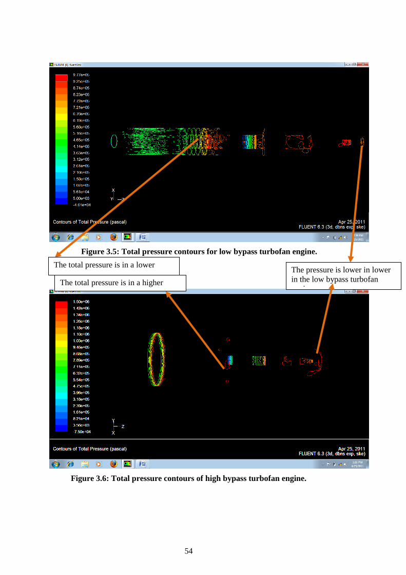
Figure 3.5: Total pressure contours for low bypass turbofan engine.
Figure 3.6: Total pressure contours of high bypass turbofan engine.
The total pressure is in a lower range.
The total pressure is in a higher range.
The pressure is lower in lower in the low bypass turbofan engine.

55
3.1CONCLUSIONS DRAWN FROM PRESSURE CONTOURS
From the figure and figure contours, it is observed that the value of pressure is higher
in case of high bypass turbofan engines as compared to the low bypass turbofan
engine at the nozzle outlet (exhaust). Since pressure is directly proportional to the
mass of fluid flowing through the engine, we can say that the mass of fluid
accelerated by the fan is higher in case of a high bypass turbofan engine resulting in
higher thrust.
The kinetic energy of the fluid is converted into the pressure energy in a turbofan
engine. As observed from the figure figure, the pressure energy at the end of the
nozzle is lower in case of a low bypass turbofan engine and thus, the kinetic energy
and hence, the velocity (exhaust) is higher than in a high bypass turbofan engine.
Therefore, it is concluded that a high bypass turbofan engine produces a lower
exhaust velocity.

56
Figure 3.7: Inlet velocity contours for low bypass turbofan engine.
Figure 3.8: Inlet velocity contours for high bypass turbofan engine.
The flow velocity at the inlet is in a higher
The flow velocity at inlet is in a lower range.

57
Figure 3.9: Outlet velocity contours for low bypass turbofan engine.
Figure 3.10: Outlet velocity contours for a high bypass turbofan engine.
The flow velocity is in a lower range. The flow velocity is in a higher range.

58
3.2 CONCLUSIONS DRAWN FROM THE VELOCITY CONTOURS
The thrust of a turbofan engine is the sum of the jet thrust and the thrust produced by
the fan
= #!$ %"% − !$ %"&' + �!$ ("( − !$ )"&� (3.1)
As seen from figure figure figure figure, the velocity at the inlet and outlet of the
core is almost same for the high and low bypass engines, whereas the inlet velocity
of the fan is higher in case of a high bypass turbofan engine. Also, though the
velocity at the exit is lower in case of the high bypass turbofan engine, the difference
between the inlet and exit velocities of the fan in a high bypass turbofan engine is
higher. Thus the thrust of the fan is higher in the case of a high bypass turbofan
engine and so is the net thrust.
The propulsive efficiency of a turbofan engine is given by:
� = ��BC
D (3.2)
Where ‘c’ is the exhaust velocity and ‘v’ is the velocity of the air vehicle. As seen
from the velocity contours at the exit of the engine, the exhaust velocity is low in
case of high bypass turbofan engine as compared to the low bypass turbofan engine.
Thus, propulsive efficiency of a high bypass turbofan engine is higher than a low
bypass turbofan engine.

59
Figure 3.11: Temperature contours for a low bypass turbofan engine.
Figure 3.12: Temperature contours for a high bypass turbofan engine.
The temperature at the exit of the nozzle is higher in case of high bypass turbofan engine.

60
3.3CONCUSIONS DRAWN FROM THE TEMPERATURE CONTOURS
From the figure figure it is observed that temperature at the exit of the nozzle in
case of a high bypass turbofan engine is higher.
One of the major functions of an exhaust nozzle is to convert the gas thermal energy
into kinetic energy. Work done by the nozzle and nozzle efficiency depend on the
temperatures at the exit of the turbine and that at the exit of the nozzle.
�E.F = 1�G�1�H1�G�1�H′ (3.3)
h04 and h05 , denote the enthalpies at the exit of turbine and nozzle respectively.
Higher the temperature difference higher will be the work done. Thus, greater thrust
is produced by a high bypass turbofan engine.

61
CHAPTER FOUR
INTRODUCTION
A turbofan engine is an internal combustion gas turbine engine. Like most of the
propulsive systems, it produces thrust by accelerating a mass of gas through it. The
main components of the engine are a fan, a compressor, a combustion chamber, a
turbine and a nozzle. Air is taken in by the fan which is then compressed in the
compressor and heated in the combustion chamber. The turbine expands the heated
and pressurized gas to obtain power. This power is used to drive the compressor. The
exhaust gases leave the nozzle with a higher velocity thus giving a thrust to the
engine.
The turbofan engine differs from the other gas turbine engines because of the
presence of a fan mounted inside the casing. Due to this arrangement, some of air
bypasses the engine core and just flows across the fan. Since this mass of air has a
higher velocity while leaving the engine through the nozzle, it contributes in
generating thrust. Thus a turbofan engine produces more thrust for almost same
amount of fuel. Ratio of mass of air that bypasses the engine to mass of air that
passes through the core is called the bypass ratio.
1.1 Material Used
Wood: To construct the shaft.
Aluminium sheets: To construct rotor and stator blades.
Cardboard: To show the combustion chamber.
Plastic sheets: To show the casing.

62
2.VARIOUS PARTS OF THE SCALE MODEL
2.1 Shaft
The shaft of the engine has been made out of wood. Its dimensions are as follows:
Diameter= 2.5 cm, Length= 45 cm
Figure 1.1: Shaft of scale model.
2.2 Compressor
The model makes use of an axial compressor. An axial compressor consists of
rotating parts called rotors and stationary parts called stators. Rotors are attached to
the central shaft rotating at high speed, while the stators remain fixed. The rotor and
stator blades have been made out of aluminium sheets with the following
dimensions:
Length= 45cm
Dia= 2.5cm

63
Figure 1.2: Compressor Blade of the scale model.
2.3 Combustion Chamber
The combustion chamber has been made out of cardboard.
2.4 Turbine
A turbine, just like a compressor consists of rotors and stators. The stators prevent
the flow from spiraling. A single turbine stage can be used to drive multiple
compressor stages effectively. It has the same dimensions as rotor and stator blades
of the compressors shown above in Figure 1.2.
L= 3cm
B= 4cm
H=4cm

64
2.5 Nozzle
After the gases leave the turbine they expand further in the exhaust nozzle and are
ejected into the atmosphere with a velocity greater than the flight velocity, thereby,
producing thrust for propulsion. The model incorporates the use of a convergent
nozzle.
2.6 Fan
The blades of the fan of the turbofan engine are made out of aluminium sheets. The
dimensions of the same are as follows:
Figure 1.3: Fan Blade of the model.
2.7 Cowling
The cowling is made out of thin transparent plastic sheets to help understand the
concept of bypass ratio. This transparency all ensures visibility of every part of the
model. This can be seen as shown in the Figure 1.4.
H= 10cm
L=3cm
B=4cm

65
Figure 1.4: Cowling of the model.
Casing made out of transparent plastic sheet. Bypass ratio is approximately 3:2.

66
CONCLUSIONS
After observing the results from all the preceding chapters the following conclusions can be drawn:
• A higher bypass ratio gives a low (actual) exhaust speed. As a result, the thrust specific fuel consumption is reduced. A lower bypass ratio gives high exhaust speed, which is used to sustain supersonic speeds. Thus, a high bypass turbofan engine gives lower thrust specific fuel consumption.
• As the true air speed increases, the thrust produced by the engine decreases. This is so because, as the speed increases, the drag between the mass of the air going into the core and the mass of the air going around it increases leading to a overall decrease in the thrust.
• As the bypass ratio of a turbofan engine is increased the value of range decreases. This is so because, as the bypass ratio increases more power is consumed in driving the fan and less thrust is produced to propel the aircraft.
• As the thrust specific fuel consumption of the turbofan engine increases, the
range decreases. Thus, one can conclude that if the rate of fuel consumption increases, then the distance travelled by the airplane with a turbofan engine decreases.
• As the thrust specific fuel consumption of the turbofan engine increases, the endurance decreases. It shows that if the rate at which fuel is consumed is increased, then the time for which an airplane with a turbofan engine can stay in air decreases.
• A high bypass turbofan engine generates greater thrust due to various reasons, some of which are as follows:
� Larger the fan in case of a high bypass turbofan engine resulting in higher thrust accelerates mass of fluid produced.
� The change in velocities between the inlet of the fan and the engine exit is higher in case of a high bypass turbofan engine, thereby, generating higher thrust.
� The temperatures at the inlet and exit of a nozzle are higher in a high bypass turbofan engine and thus larger work is done.
• A high bypass turbofan engine produces low exhaust speed. Thus, it has a higher propulsive efficiency as compared to a low bypass turbofan engine. In

67
addition, high bypass turbofan engine is used at subsonic speeds because of low exhaust speed it produces. This report justifies the importance and use of high bypass turbofan engine owing to its larger thrust, high propulsive efficiency and low thrust specific fuel consumption.
FUTURE WORK With greater number of iterations performed on these engine models in CFD, a
much-advanced flow can be developed. This project enables one to understand the
significance and need of turbofan engines with respect commercial aircrafts.

68
REFERENCES
[1] <http://adg.stanford.edu/aa241/propulsion/propulsionintro.html>, accessed at 15.02.2011.
[2] <http://en.wikipedia.org/wiki/Bypass_ratio>, accessed at 04.01.2011.
[3] <http://www.airliners.net/aviation-forums/general_aviation/read.main/76442/>, accessed at 07.02.2011.
[4] <http://www.fluent.com>, accessed at 19.02.2011.
[5] <http://www.grc.nasa.gov/WWW/K-12/airplane/turbfan.html>, accessed at 06.02.2011.
[6] <http://www.stanford.edu/~cantwell/AA283_Course_Material/AA283_Course_Notes/Ch_05_Turbofan_Cycle.pdf>, accessed at 07.02.2011.
[7] Anderson Jr., John D., 1995. McGraw Hill, Inc.,“Computational Fluid Dynamics: The Basics with Applications” , New York, USA.
[8] Ganesan, V., 2010. Ajay Shukla, Tata McGraw Hill Education Private Limited, “Gas Turbines” , West Patel Nagar, New Delhi 110 008.
[9] Hale, Francis J., 1984. John Wiley & Sons, Inc., “Introduction to Aircraft Performance, Selection and Design”, Canada, USA.