student workbook tp2008 freight car brake …...june 2004 tp2008 7 brake rigging arrangements 2....
TRANSCRIPT

Freight Car BrakeRigging Arrangements
TP2008
June 2004
Student Workbook

1June 2004 TP2008
Brake Rigging Arrangements
Disclaimer
Thank you for making Wabtec Corporation your choice for educational material.
All our training publications are designed as teaching tools for a specific area of railway equipment instruction.As with any training literature, it will eventually become out of date. For this reason, it is important that only thecurrent edition of this training package be used. To ensure you have the current edition please contact yourWabtec representative. Wabtec Corporation produces a line of instructional pamphlets and brochures foreach of the components that Wabtec manufactures to help augment the training process. This publication isunder copyright to the Wabtec Corporation. Any reproduction in whole or in part without written consent froman officer of Wabtec Corporation is strictly prohibited.
This book may contain information covering some products manufactured by companies other than Wabtec.This is done to give you, the user, an opportunity to utilize one manual for the majority of your trainingrequirements.
Information covering products not supplied by Wabtec Corporation is provided as a general guide as to howthese products should perform. Wabtec Corporation accepts no responsibility for the operation of productssupplied by others, nor the information stated herein as to design or intended dimensional limits of such products.
Technical questions on the equipment shown in this booklet should be directed to the original manufacturer. Ifthere are any discrepancies between this book and the original manufacturer standards, the original manufacturerinstructions take precedence.
Wabtec Corporation accepts no responsibility for injury or damage to personnel or equipment resulting fromeither direct or indirect use of this manual.
For Technical Support contact your local Wabtec Corporation representative or Wabtec Training in Wilmerding,Pennsylvania, USA at 412-825-1453.
Michael Zenert(Michael Zenert)Manager - Air Brake TrainingWabtec Corporation
© 2003 Wabtec Corporation

Brake Rigging Arrangements
2 June 2004TP2008
ContentsIntroduction .......................................................................................................................................... 3
Part 1: Freight Car Locations................................................................................... 3
Part 2: Freight Brake Rigging................................................................................... 4
A. Foundation Brake Rigging ............................................................................. 31. Push Rod2. Brake Levers3. Dead Lever Guide4. Truck Lever Connections5. Brake Rods & Pins6. Brake Beams7. Brake Shoes8. Automatic Slack Adjusters9. Brake Levers & Rod Carrier Supports10. Brake Badge Plate11. Truck Brake Rigging
B. Hand Brake Arrangements ........................................................................... 121. Body Mounted Brake Arrangement2. Truck Mounted Brake Arrangement3. Bell Cranks and Sheave Wheels
C. Special Brake Arrangements ........................................................................ 14
Part 3: Brake Rigging Adjustments .........................................................................151. Lever Angularity2. Piston Travel
Review Exercise

3June 2004 TP2008
Brake Rigging Arrangements
Introduction
Understanding the operation of the brake rigging provides a carman with the ablility to make repairs thatwill ensure the rigging components function as designed, proper braking forces are acheived and there isreduced possiblity of personal injury or property damage while working on the equipment.
Body mounted or conventional brake rigging on freight cars uses a body mounted brake cylinderlocated approximately in the center of the car.
The majority of coal cars (open top hoppers or gondolas) are equipped with body mounted brakeassemblies mounted on the end of the car. This design has the brake cylinder in close proximity to thecontrol valve and other brake devices.
Early conventional rigging arrangements used rods and levers attached to the underside body of thecar with a manual type slack adjuster. To ensure there was minimal slack in the brake rigging and thepiston travel stayed consistant, the carman or inspector had to adjust the rigging though moving themanual adjuster on the brake rigging assembly. Conventional rigging today uses automatic or self adjustingslack adjusters to do the same job of manually adjusting the brake rigging.
Other car designs use truck mounted brake arrangements. This design eliminates a lot of the riggingnecessary for conventional rigging by having the brake cylinder attached directly to the truck riggingassembly.
In this manual the various types of brake rigging is covered showing the relationship of the levers,rods, pins, brake cylinders, slack adjusters and handbrakes have on the overall operation of a typicalrail car.

Brake Rigging Arrangements
4 June 2004TP2008
Part 1: Freight Car Locations
Understanding the locations on a freight car isbasic to identifying and repairing items requiringattention or finding defects on the car. The basiclocations are generally the same on all freight cars.
This diagram shows how locations are identifiedon a typical freight car. The end of the car with thehandbrake is the “B” end. The opposite end of the caris the “A” end. When standing at the B–end facing thecar, everything on the right is the “R” or right side,everything on the left is the “L” or left side.
Multiple component parts such as wheels andaxles are numbered consecutively starting at the B-end.
The car is also divided into quarters using theend and side location as a reference (i.e. “AR” is A-end, right side. “BL” is B-end, left side. ).
Conventional brake rigging may have the brake cylinder underthe car body. In such cases, the brake cylinder piston push rodpoints to the B-end. This provides a more direct connection ofthe handbrake to the brake cylinder and rigging assembly.
On cars with more than one handbrake, check the brakecylinder to indicate the B-end of the car. Cars with multiplehandbrakes and brake cylinders generally have the locationsstenciled on the side of the car. See AAR Field Manual Rule 83for more information.
B-End
A-End
R-SideL-Side
1
2
3
4
AR
BRBL
AL
Handbrake
BrakeCylinder

5June 2004 TP2008
Brake Rigging Arrangements
Part 2: Freight Brake Rigging Arrangements
The freight car brake rigging is the metal components assembled together to transmitt a brake applicationdirected by either the handbrake or the air activation of the brake cylinder(s). Brake rigging can be in the formof a body mounted brake assembly with foundation brake rigging or truck mounted brake assemblies.
A. Conventional or Foundation Brake Rigging
This is an example of foundation brake rigging. Various cars may be slightly different depending onthe car body design. The main components covered in the following pages have the same function on allcars.

Brake Rigging Arrangements
6 June 2004TP2008
1. Push Rod
The brake cylinder push rod is a solid rod with a jaw formed on one end. A brake pin is inserted intothe jaw end to make the connection to the brake rigging. The push rod transmits the force caused by the“push” of air entering the brake cylinder or by the “ pull” of the hand brake, through levers and rods tothe brake shoes. The push rod is not connected to the piston. The push rod end fits loosely in the tube ofthe piston hollow rod. At one time, push rods were of different lengths; however, most present day pushrods used for 10 x 12 brake cylinders are a standard length of 26-1/4” from the ball end to the center lineof the hole in the jaw. The push rod is designed to provide adequate movement of the jaw end withoutbinding in the piston-hollow rod. When performing a Single Car Test in accordance with AAR S-486,one of the requirements is to make sure the push rod will go all the way back into the hollow rodassembly of the piston. This check is done to ensure the movement of rods and levers is not binding orfouling.
Brake Cylinder Push Rod

7June 2004 TP2008
Brake Rigging Arrangements
2. Brake Levers
Brake levers are used throughout the brake system to transmit, increase, or decrease braking force. Theyare also used to transfer or changedirection of force. Levers are namedfor the various conditions and positionsthat they serve in the system. Thereare body levers, such as the cylinderlever and fulcrum lever. There aretruck levers, such as the live lever, dead lever, and horizontal truck lever. Minimum thickness for leversis 1”, with minimum 1-1/8” diameter pin holes.
3. Brake Connecting Rods
The brake connecting rods are used to connect the body levers with the truck levers. The center toprod (shown here) connects two body levers joining one end of the brake rigging to the other. The leversand rods are connected together by brake pins. It is very important that these connecting rods and pins inthe brake rigging be of proper length and size. Improper lengths may cause binding or fouling. Check thecar badge plate for the correct length when replacing connecting rods. Wear limitation for connectingrods is in accordance with AAR Field Manual Rule 11. The AAR has designated that rod diameters mustnot be less than ¾” and pin diameters must not be less than 1-3/32”.
PushRod
BrakeLever
Chain ConnectionTo Handbrake
Brake Cylinder
Top Connecting Rod

Brake Rigging Arrangements
8 June 2004TP2008
4. Brake Levers
Brake levers are mounted as part of the brake rigging under the car body and as part of the truckbrake assembly. The levers are used to transmit the pulling or pushing forces exerted by the connectingrods. Each brake lever is a specific size designed to amplify or reduce the brake force. This is determinedby the distance between the pin connections. Check the badge plate for the proper distance between theholes for each lever. When the holes in the lever become elongated or show excessive wear they do notprovide correct braking force. Check AAR Field Manual Rule 11 for wear limits.
5. Dead Lever Guide
The dead lever guide and bracketare used to fulcrum one end of the truckdead lever to the truck bolster or to thecar body. This provides an anchor forthe brake arrangement. A multi-holedead lever guide is attached to the deadlever bracket. Some dead leverbrackets may be anchored to the truckbolster or the center sill of the car. Thedead lever guide allows for manualadjustment of the brake rigging. A one-hole dead lever guide, attached to thetruck bolster, is used with all double-acting automatic slack adjusters toprevent the manual adjustment ofbrakes. A dead lever anchor serves thesame purpose as the one-hole deadlever guide, the difference being thedead lever anchor is attached to thecar body.
6. Truck Lever Connections
Truck lever connections are sometimes called bottom rods. There are two types of bottom rods, onethat passes through the truck bolster and one that passes under the truck bolster. The purpose of this rod isto transfer the force from the truck live lever to the truck dead lever. The truck lever connections arefurnished in various lengths with two or three holes in each end. The purpose of these holes is to provideadjustment required to maintain good truck lever angularity when different diameter wheels are applied;i.e., two wear wheels machined to a one wear tread contour.
Dead LeverGuide
BrakeLever
Dead LeverBracket
Dead Lever Guide

9June 2004 TP2008
Brake Rigging Arrangements
7. Brake Beams
Brake beams are used to transferthe force from the truck levers to thebrake shoes. They are of trussconstruction consisting primarily oftension and compression membersattached at the ends where the brakeheads are located and separated at themiddle by a strut, at which point thetruck lever is attached. Brake beamsare designated according to thecapacity. For example, an A.A.R.Number 24 beam has an 24,000 pounddesign capacity. The size of the brakebeam to be used is determined by thebraking forces required for the car.
Most brake beams today are slidingor unit type. Unitized brake beams are equipped with an extension on each end of the bream. Thisextension fits into a slot in the truck side frame, it will align the beam to move or slide at the correctangle for the brake shoes to makecontact with the wheels. There areseveral types of sliding or unitizedbeams that are designed for specificapplications.
WABCOPA C/ NYCOPA Cbrake beams are much larger andheavier than the one pictured here.They have a brake cylinder mountedon each beam.
On Wabtec TMX TruckMounted brake equipment, thebrake beams are designed with thecenter area bent down. This is toallow for the brake cylinderconnecting rod and the automaticslack adjuster passing through the openings in the bolster. See the section on truck mounted brake equipmentin this manual for more information.

Brake Rigging Arrangements
10 June 2004TP2008
Brake Beam OrientationBrake beams are either left or right hand according to the angled direction
of the brake lever slot in the brake beam strut. This provides for proper leverangularity of the brake rigging. To determine the correct slot direction, thebeam must be sitting with the AAR printing on the top side or the word “TOP”showing on the beam. Stand on the back end of the beam and check the directionthe slot opens, to your right hand or left hand. If the brake beam opens to theright, it is a right hand beam. Left hand beams are orientated the same way.(see picture below of left hand beam)
The brake beam heads located at each end of the beam are designed toaccept or reject either cast metal or composition type brake shoes.The brakeshoes are set up with rejection lugs designed to fit the correct type of brakehead. The car brake configuration will determine the type of brake shoesstandard to the car.

11June 2004 TP2008
Brake Rigging Arrangements
8. Brake ShoesBrake shoes transmit the braking force to the wheels providing a retarding motion on the car.
Brake shoes are designated by type and thickness to fit the proper brake heads. There are two generaltypes of brake shoes: cast metal ( cast iron) and composition.
Cast Iron brake shoes were used on older cars. New cars are designed with composition shoes.High Friction Composition shoes have approximately twice the stopping ability of cast metal shoes. Forthis reason cast iron brake shoes are not interchangeable with composition brake shoes. As shownbelow the brake head is designed for only one type of brake shoe.
a. Cast Iron Brake ShoesCast Iron brake shoes were the original shoe used for railroad brake equipment. Typically used on
cars with hanger type brake beams, body mounted brake equipment and AB control valves. They requirehigher braking force to stop or slow a car/locomotive than high friction composition shoes. Drawbackswith the cast iron shoes include sparking and uneven wheel wear. Note: AAR Circular Letter c-9736adds to AAR Field Manual Rule 12 “The application of cast iron brake shoes is prohibited effectiveon 1/1/05.” Converting a car from cast iron to High Friction Composition shoes, the brake equipment ofthe freight car must be adjusted in one of several ways.
1. Change brake lever ratios - cast iron requires more braking force than high friction. Simplychanging the shoes will result in excessive brake force on the wheel with brake related wheeldefects.
2. Change brake cylinder size - Having a smaller brake cylinder will result in less force of the shoeon the wheel providing that the full service brake application equalization pressure remains withinAAR limits.
3. Use a modulating valve - A modulating valve will divert some of the air from the brake cylinder toa separate volume.
Note: Conversion of a locomotive from cast iron to High Friction Composition shoes requires changingthe J type relay valve or as a simpler alternative switch to Low Friction Composition shoes.
Cast Iron Composition

Brake Rigging Arrangements
12 June 2004TP2008
COBRA® LF CompositionBrake Shoe with insert
Insert
b. Low Friction Composition
The COBRA® LF low friction composition brake shoes aredesigned as a cost effective alternative to cast iron shoes.Introduced in 1997, the low friction shoe was designed for useon locomotives equipped with cast iron shoes as a directreplacement for the cast shoes. The benefits of using the LFshoe is longer life, lighter weight and less maintenance. Lowfriction composition shoes are also used on freight equipment.
COBRA LF shoes will fit into the brake heads designed toaccept cast iron shoes, but the rejection lugs will not permit theshoes to be applied to the brake heads designed for high frictioncomposition shoes.
Every new COBRA LF Composition shoe is painted brightyellow for immediate identification. This will alert the installeras to the type of replacement shoe required even before the oldshoe is renewed.
The new COBRA® LF Composition Brake Shoe has a castiron insert in the center of the shoe. The insert conditions thewheel tread, thereby reducing the potential for wheel damage.
Modulating Valve Applied to Brake Cylinder

13June 2004 TP2008
Brake Rigging Arrangements
c. Hi-Friction Composition
High Friction Composition brake shoes weredesigned as an alternative to the cast iron brakeshoe. The HF composition shoe has a highercoefficient of friction that provides better brakecontrol with less brake head force than the cast ironshoe.
COBRA® AP Advanced Performance HighFriction Composition Brake Shoes are designed tobetter adjust to the curvature of the wheel.
d. TreadGuard Shoes
Tread damage, such as shells and spalls, cancreate major expenses in maintenance. The COBRATG Brake shoe is designed to reduce wheel treaddamage. Designed with the same tapered shape asthe COBRA AP Brake Shoes, the COBRA TG BrakeShoes have added value built into them. The shoeshave a metal insert molded into the friction material in the center of the shoes that works in two ways.
First, it slightly roughens thetread surface to improve wheeladhesion, thereby decreasing thelikelihood of wheel slides. Second,because the insert is more abrasivethan the base composition material,it works continuously to removeminor tread damage and improvethe condition of the tread.
COBRA® TG Brake shoes arepainted red for immediateidentification. If changing brakeshoes due to wear, ensure that thecorrect replacement shoe isapplied. When removing aTreadGuard Shoe they should bereplaced in kind in accordance withthe car owners specifications. TheTreadGuard Brake Shoe also hasa decal applied to the insideportion of the shoe foridentification.
COBRA® High FrictionComposition Brake Shoe
COBRA® TreadGuard (TG) High FrictionComposition Brake Shoe
insert

Brake Rigging Arrangements
14 June 2004TP2008
Actuating ControlRod
Control Collarand Adjusting Screw
Slack Adjuster
Universal Model 2300 DJ (body mounted)
9. Automatic Slack Adjusters
Mechanical automatic slack adjusters are designed to compensate for slack caused by wear, thatoccurs to the brake shoes, wheels, and other components in the brake rigging. By controlling this slack,the air brake piston travel is maintained at the correct length to ensure maximum efficiency in the brakesystem.
Most automatic slack adjusters are double jawed and designed for application on;1. Conventional or Foundation brake rigging2. Truck mounted brake assemblies.
The main difference in the two designs is the size and operation. Body mounted automatic slackadjuster used for foundation brake rigging are designed for center rod or top rod application.Bodymounted slack adjusters take up slack as the components wear down. Truck mounted slack adjustershave the same function however they operate to extend as the brake shoes wear down. Truck mountedslack adjusters are also much smaller than body mounted adjusters. They are attached in place of abottom rod connection on the truck assembly.
a. Body Mounted Slack Adjuster
The body mounted slack adjuster operates as an adjustable rod that automatically shortens as thewear occurs or extends as new brake shoes or new wheels are applied. The total length of a bodymounted slack adjuster fully extended is 84”. The installed length on a new car isnominally 81”, measured from centerto center of the pin holes located in theadjuster jaws. This dimension will varyon a car in service according to theamount of brake shoe and wheel wear.The Group E or double jaw modelslack adjusters, along with theirdesigned control mechanism, areinterchangeable with each other.
The body mounted automatic slackadjuster is equipped with a actuatorcontrol rod that is connected to the bodyof the slack adjuster by a control collarwith an adjusting screw. The actuator control rod is pinned to the top rod end of the cylinder lever andfulcrumed at the control lever fulcrum bracket. The purpose of the control lever (drilled in proportion tothe cylinder lever hole drilling) is to activate the slack adjuster. It does not transfer or regulate thebraking force on the car. The actuator control rod collar is moved depending upon the piston traveladjustment required. Once the piston travel has been adjusted to the correct length, the adjusting screw issecured. To ensure the adjustment does not change the collar on the actuator control rod must be weldedin place in accordance with AAR Field Manual Rule 4.

15June 2004 TP2008
Brake Rigging Arrangements
b. Truck Mounted Adjusters
Truck mounted slack adjusters work the opposite of body mounted slack adjusters. As the brake shoeswear down, because of their location on the truck assembly, the slack adjuster gets longer. They maintainthe correct slack through the use of an actuator control rod or a control lever (see the following types).
Universal Model 5D- Used on Thrall/Davis truck mounted brake assembly- Has a 5” let out capacity- Is the replacement for the Model 7D
Universal Model 85- AAR approved, used to upgrade WABCOPAC truck mounted brake arrangement to WABCOPAC II- 8-1/2” let out capacity
Universal Model 5- Used on TTX truck mounted brake assembly- 5” let out capacity- Replacement for the Model 7- Jaws painted orange for identification
Universal Model 85
Model 5D
Model 5

Brake Rigging Arrangements
16 June 2004TP2008
Trigger Pin/Locking Bolt
Universal Model C-1000- AAR approved, used in TMX truck mounted brake system- 9-3/4” let out capacity
* Note; the Model 5, 5D and Model C-1000 areequipped with a Trigger Pin/Locking Bolt assemblydesigned to prevent slack adjuster extension until theUniversal compression slack adjuster is properlyinstalled.
10. Brake Levers and Rod Carrier Supports
Brake lever and rod carrier supports are applied to the car at various locations to support the leversand rods in their respective positions. Importance is stressed on the size and location of the carriersbecause of the movements of the levers as the brakes are applied and released and as the shoe and wheelwear changes. Care should be given in application of these carriers to prevent any binding in the brakerigging.
11. Brake Badge Plate
The brake badge plateis a metal plate designed toprovide brake riggingdimensions that may not bereadily available. Theinformation on a badge platemay include brake lever-drilling dimensions,handbrake chain length,piston travel, length of topconnecting rods, bottomconnecting rod length, etc.The badge plate is especially usefull for repairs to the brake rigging or toverify the correct piston travel or to check proper lever dimensions. The badge plate is generally locatednear the air brake cylinder or control valves.
Universal Model C-1000

17June 2004 TP2008
Brake Rigging Arrangements
12. Truck Brake Rigging
The freight car trucks not only support the car but also assist in stoppingor holding the car through the use of the air brake or hand brake forcesexerted through the brake shoes to the wheels. Freight car trucks aredesignated by the truck lever arrangements. Truck mounted brakecylinder, lever arrangements generally use less component parts toprovide the same braking effectiveness as body mounted brakes.
Part 3: Handbrake Arrangements
1. Body Mounted Brakes
Body mounted brake equipment has the bottom connecting rodrunning through the opening in the bolster or the bottom rod under thetruck bolster. The picture below shows a rod-through design. Noticethe truck lever connection passing through the truck bolster is pinned tothe center hole of each truck levers. The bottom holes of the trucklevers are pinned to the brake beams. The top rod, which is pinned tothe top of the live lever, must pass over the truck bolster to connect to a body lever. The top end of the deadlever is usually fulcrumed to the truck bolster by the dead lever guide. The truck levers usually have a 2 to 1ratio so the forces exerted at the brake shoes are twice that of the top rod force. Conversely, the top rodmovement is 4 times the movement of the brake beam. When the handbrake is applied, the levers and rodsmove in direct relationship to the movement of the body lever. The body lever is connected to the piston pushrod. In this way the brake shoes are force against the wheel on an application of the brakes whether theapplication is directed by the handbrake or the force of the brake cylinder piston as shown in the diagramhandbrake. Note the dead lever bracket and guide are used as an anchor to maintain the correct force appliedat the shoes.
Handbrake Wheel
BellCrank
Handbrake Appliedto Boxcar

Brake Rigging Arrangements
18 June 2004TP2008
Truck assemblies with the bottom connecting rod under the truck bolster function in a similar manner witha couple of exceptions. The bottom rod or connecting rod being under the bolster is pinned to the bottom holeof each truck lever. The center holes of the truck levers are connected to the brake beams and the top leverholes are for the top connecting rod and dead lever guide. AAR Rule 11 provides for inspection and wearlimitation on this type of connection.
2. Truck Mounted Handbrake Arrangement
The operation of truck mounted handbrake assemblies is similar to body mounted handbrake arrangementsexcept there are less components. In the diagram below is a typical WABCOPAC. Note the handbrake isconnected to the brake beam through levers and connecting rods. This will ensure there is a direct brakeapplication similar to what is provided by the air activated brake cylinder.
New truck mounted brake equipment and changes to car design has resulted in more types of truckmounted brake assemblies available. Some common types of truck mounted handbrake arrangements in useare on Cardwell/WABCO TMX, Ellcon National TMB, Thrall Davis TMB and TTX TMB and NYAB hasseveral types available. Each of these designs has the brake cylinder(s) mounted on the brake beam or applieddirectly to the truck bolster. The cylinder force acts directly on the brake beams without intermediate leversand rods to push the brake shoes against the wheels. The forces exerted at the brake shoes are the actualoutput force of the cylinders. Each of these types of truck mounted brake arrangements is discussed in theSingle Car Test Workbook and Booklet (WAB/SCT-1 , 2).
The WABCOPAC shown here uses two brake cylinders per truck. In 1966, it became a manditoryrequirement to apply automatic slack adjusters on all new cars. Since 1968 this also applied to all rebuilt cars.However there still are many cars equipped with WABCOPAC and NYCOPAC truck mounted brakes.

19June 2004 TP2008
Brake Rigging Arrangements
3. Bell Cranks and Sheave Wheels
Handbrakes are designed to provide a brake force of the shoes against the wheel by indirect pull of therods and levers on the truck assembly. The bell crank is common on older style cars where a lot of new carsuse sheave wheels. In both cases they are used to change the vertical pull of the handbrake to ahorizontal pull on the rigging.
When performing a Single Car Test per AAR S-486, the carman must check the position of the bellcrank with the brakes applied. This si because the bell crank has fixed positioning. When the handbrakeis applied the pull of the handbrake will cause the fulcrum of the handbrake to rise pulling the horizontalchain. If the bell crank rises too high, there will not be enough force on the shoes to hold the car inposition. On cars with an automatic slack adjuster, as the shoes wear down the bell crank should stay inthe correct position. On cars without an automatic slack adjuster (WABCOPAC/NYCOPAC) as thebrake shoes wear down the positioning of the bell crank will change. The inspector must consider thiswhen checking the positioning of the bell crank during the air test.
The use of either device depends upon the design of the car. Both handbrake designs shown in theprevious pages use a bell crank. Sheave wheels are used extensively on cars carrying intermodal andautomobile traffic.
4. Special Brake Arrangements
Speicalized cars such as depressed center flat cars and other cars of higher capacity may havetrucks equipped with six, eight, ten or twelve-wheel sets. These cars may also have more than onehandbrake, typically one at each end. The brake arrangement of each car will vary according to thebrake shoe forces that are applicable to the car design and the car weight on the rail. The brakingarrangement will normally employ many of the items identified in this booklet.

Brake Rigging Arrangements
20 June 2004TP2008
Bell Crank
Sheave Wheel

21June 2004 TP2008
Brake Rigging Arrangements
Part 4: Foundation Brake Rigging Adjustments
To ensure the proper braking forces are exerted by the shoe against the wheel, the brake rigging must bein good condition and applied correctly to the car. Wear, improper applications and damaged brake riggingcomponents have a detrimental effect on the braking efficiency and must be corrected to ensure adequatebraking for that car. Even though most cars are now equipped with automatic slack adjusters, the truck leversmay occasionally be out of adjustment.
This section of the booklet will deal with some adjustments that can be made to the body mounted brakerigging to ensure that braking forces are sufficient to effectively stop a freight car. Before performing anyadjustments to the brake rigging, ensure that the car brakes are released and there is no air in the brake system.This is done to prevent unintentional brake applications while someone is working on the brake equipment.
1. Lever Angularity
Angularity is the angle relationship of levers within the brake rigging assembly. If the angularity of the carbrake rigging is incorrect, the rods and levers may bind or foul on other car and/or brake rigging components.This conditions would provide ineffective braking forces on that car.
Truck Lever Angularity
Truck lever angularity changes when brake shoes and wheels wear. The automatic slack adjuster willcompensate for the wear of the shoes and wheels in normal applications. When wheels are changed, it mayeffect the lever angularity. Therefore as common practice, the brake lever angularity should be checked eachtime wheels are changed. For this reason, the leverangularity could be different on each truck of thesame car.
Correct truck lever angularity is when the livetruck lever is perpendicular to the top rod, whenthe brakes are fully applied.
Application of new wheels and brake shoesimproper application of brake rigging components,and wear to rigging components can cause poortruck lever angularity. If the truck lever angularity isincorrect, adjustment should be made to maintaincorrect brake shoe pressure on the wheel for eachbrake application.
Correct Truck Lever Angularity

Brake Rigging Arrangements
22 June 2004TP2008
The common location for adjustment of truck lever angularity is at the bottom rods (truck lever connections).Bottom rods may have more than one set of holes at each end of the rod. Any brake shoes that are wornbeyond AAR limits should be changed before making adjustments to the truck levers and rod connections.The dead lever guide can also provide a location for lever angularity adjustment. To correct the incorrect trucklever angularity shown below:
1. Cut-out the car’s air brake2. Disconnect the brake rigging to the automatic slack adjuster or manual slack adjuster3. Remove the brake pin from the bottom rod/live lever connection4. Move the live lever to line up the bottom rod next outside hole5. Apply the brake pin.6. Physically move the lever by hand to apply the shoes to the wheel to check adjustment7. If the lever angularity requires more adjustment repeat steps 4, 5 and 6 until correct angularity is
obtained.8. Movement of the bottom rod must not set up a situation where the live lever rests on the axle. If this
happens adjustment of the dead lever guide may be necessary. Note that movement of the deadlever has a more dramatic effect on the live levers than movement of the bottom rod connection.
Poor Truck Lever Angularity

23June 2004 TP2008
Brake Rigging Arrangements
Body Lever Angularity
The movement of the truck levers will affect the body lever angularity. If a car is equipped with brake rodsand levers of the proper length, correct truck lever angularity will produce correct body lever angularity.
Correct body leverangularity is when the leversare perpendicular to thebrake rods when the brakeshoes and wheels are one-half worn.
Incorrect brake rodlengths and lever lengths willproduce incorrect body leverangularity.
If the body lever angularity is incorrect, first measure the levers and rods and ensure the measurements onthe rods and levers correspond to the badge plate dimensions. If they do not match the badge plate correctiveaction is necessary before changing angularity. With correct truck lever angularity and correct body leverdimensions, body lever angularity can only be adjusted by changing rod length.
Correct Body Lever Angularity
Incorrect Body Lever Angularity

Brake Rigging Arrangements
24 June 2004TP2008
2. Piston Travel
Piston travel is the distance the brake cylinder piston moves from the “brakes released” position to the“brakes applied” position. Of the various types of brake cylinders, each design has a specific piston travelallowed by design to provide maximum braking force required to control and stop that particular car. Bodymounted brake cylinders are designated by size. A 10 X 12 brake cylinder has a 10” diamenter and a 12”stroke.
Piston travel on a car with a standard body mounted brake cylinder is initially set at 8 inches for equalizationpurposes per AAR S-401. Piston travel must be set to proper length in accordance with AAR S-486 beforecar is allowed into service. Piston travel with body mounted brake rigging and an automatic slack adjuster isnormally set at seven and one-half (7 1/2) inches. When testing cars in accordance with the AAR S-486,allowable piston travel for this type of brake cylinder is seven to nine (7-9) inches. Piston travel of less thanseven inches or more than nine inches must be adjusted to a nominal seven and one-half inches.
Piston travel on a standard body mounted brake cylinder is measured from the face of the brake cylindernon-pressure head to the “grease line” near the piston collar. This “grease line” has been established by theAAR as the measuring point for the brake cylinder piston shown.
BrakesReleased
BrakesApplied
Body Mounted Brake Cylinder
Measuring Piston Travel
Piston Travel
Grease LineNon-Pressure Head

25June 2004 TP2008
Brake Rigging Arrangements
Piston travel for other types of brake cylinders as identified in the AAR Field Manual Rule 3.
FREIGHT EQUIPMENT PISTON TRAVEL
Brake Cylinder Type Proper +/- Air Test Maximum Travel Allowance Travel
*Body Mounted 10" x 12" 71/2" 1/4" 6" to 9" 101/2"
*Body Mounted 81/2" x 12" 71/2" 1/4" 6" to 9" 101/2"
*Body Mounted 71/2" x 12" 71/2" 1/4" 7" to 9" 101/2"
*Body Mounted 12" x 10" 51/2" 1/4" 5" - 7" 81/2"
*75/8" x 12"x 9" UC 51/2" 1/4" 5" - 6" 71/2"
* Triax-II 13/4" 1/8" 11/2" - 3" 31/4"
WABCOPAC/NYCOPAC 11/4" 1/4" 3/4" to 3" 4"
WABCOPAC II 21/4" 1/4" 1-3/4" to 3" 31/4"
WABCO TMX 2" 1/4" 11/2" to 3" 31/4"
NYCOPAC IIA N/A N/A N/A 21/4"
Ellcon National 23/4" 1/4" 21/4" to 3-3/4" 4"
Thrall Davis 31/4" 1/4" 23/4” to 4 1/4" 41/2"
TTX TMB (Misner) 8" 1/8" 71/2” - 10" 101/4"
* Not shown in this booklet, see AAR Field Manual Rule 3 * For piston travel not shown or identified in the AAR Field Manual, contact the car owner.

Brake Rigging Arrangements
26 June 2004TP2008
Review Exercise
1. By AAR designation the top connecting rods must be a minimum of_______________.
2. The handbrake end of the car is generally designated as the __________________.
3. Body mounted slack adjusters generally use an ____________________________to maintain the proper piston travel.
4. Brake Lever dimensions may be found on the _________________ which is usuallylocated close to the brake valves.
5. The Universal ______________________________ are equipped with a TriggerPin/Locking Bolt for safety.

27June 2004 TP2008
Brake Rigging Arrangements
Part 4: Truck Mounted Brake Equipment
A. TMX Truck Mounted Brake Equipment
Safety Procedures & Warnings
Regular yard and shop safety procedures MUST BE followed when working on this assembly.
• When performing any test or work on devices or equipment while they are on the vehicle(on car test, etc.) special precautions must be taken to insure that vehicle movement willnot occur which could result in injury to personnel and/or damage to equipment.
• The use of an air jet, which must be less than 30 p.s.i.g., to blow parts clean or to blow themdry after being cleaned with a solvent will cause particles of dirt and/or droplets of thecleaning solvent to be airborne. Wire brushing may also cause particles of dirt, rust, andscale to become airborne. These conditions may cause skin and/or eye irritation.
• Personal eye protection and gloves must be worn when performing any work on this deviceor its components parts to avoid personal injury.
• Assembly may be under a spring load. Exercise caution during disassembly so that noparts “Fly Out” and cause bodily injury.
• All air supply to this device and/or to any components part must be cut-off before thisdevice and/or any component part is removed from the equipment arrangement.
• Brake Cylinder and Slack Adjuster assemblies are under spring load. Extreme cautionmust be taken when working around or removing the slack adjuster since inadvertentoperation of the trigger mechanism may cause severe bodily harm. Care must be takenduring disassembly of both brake cylinders and slack adjuster to prevent personal injuryfrom parts that may “fly out”.
• When applying and releasing air pressure to this assembly, all personal must stand clearto minimize the potential for bodily injury from moving parts.
• Prior to removing any of the TMX components, all air must be depleted to guard againstpersonal injury from inadvertent movement of any of the parts.
• After any work is performed on this assembly an operational test must be performed toinsure the unit on the truck and the total car brake system operates as intended before thecar is released for service.
Brake Rigging Arrangements
28 June 2004TP2008
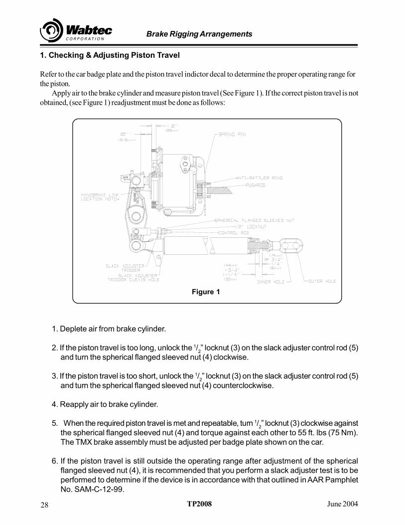
1. Checking & Adjusting Piston Travel
Refer to the car badge plate and the piston travel indictor decal to determine the proper operating range forthe piston.
Apply air to the brake cylinder and measure piston travel (See Figure 1). If the correct piston travel is notobtained, (see Figure 1) readjustment must be done as follows:
1. Deplete air from brake cylinder.
2. If the piston travel is too long, unlock the 1/2” locknut (3) on the slack adjuster control rod (5)
and turn the spherical flanged sleeved nut (4) clockwise.
3. If the piston travel is too short, unlock the 1/2” locknut (3) on the slack adjuster control rod (5)
and turn the spherical flanged sleeved nut (4) counterclockwise.
4. Reapply air to brake cylinder.
5. When the required piston travel is met and repeatable, turn 1/2” locknut (3) clockwise against
the spherical flanged sleeved nut (4) and torque against each other to 55 ft. lbs (75 Nm).The TMX brake assembly must be adjusted per badge plate shown on the car.
6. If the piston travel is still outside the operating range after adjustment of the sphericalflanged sleeved nut (4), it is recommended that you perform a slack adjuster test is to beperformed to determine if the device is in accordance with that outlined in AAR PamphletNo. SAM-C-12-99.
Figure 1

29June 2004 TP2008
Brake Rigging Arrangements
7. The car is not to be released for service until the piston travel is within the specified range.
2. Brake Cylinder Removal
Make sure all air is depleted in the brake system to preclude personal injury. Refer to Figure 2 for thisprocedure.
1. Remove brake cylinder hose from the brake cylinder air flange face and protect all exposedpiping from dust and contaminates. Remove the truck from under the car, if possible.
WARNING: DO NOT BUMP THE SLACK ADJUSTER TRIGGER! IF BUMPED, THESLACK ADJUSTER COULD ACTIVATE AND SUDDEN LET-OUT OF THE RACKEXTENSION COULD OCCUR AT THE REAR JAW. PERSONAL INJURY MAYRESULT.
2. Deactivate the slack adjuster by loosening the 1/2” locknut (3) from the spherical flanged
sleeved nut (4) and remove both nuts from the slack adjuster control rod (5). Also, screwin a 5/
8” X 2” bolt (10D) in the threaded hole in the slack adjuster housing weldment (10).
Figure 2

Brake Rigging Arrangements
30 June 2004TP2008
3. Remove the cotter pin connection (1) from the slack adjuster control rod pin (2) and removethe control rod pin.
4. Remove cotter pin connection (10B) from the slack adjuster trigger pin (10A). Remove theslack adjuster trigger pin (10A) from the slack adjuster (10).
For hand braked trucks only – remove the cotter pin (12) from the transfer link pin (13)and remove the transfer link pin (13) from the handbrake lever (14) and the handbraketransfer link (30). Lift the handbrake lever out of the handbrake strut bracket (17).
5. Remove cotter pin connections (19, 27) from the transfer pin (20) and the center strut pin(28).
WARNING: PROTECTION SHOULD BE TAKEN AGAINST HEAT DAMAGE TO THECYLINDER DUST BOOT.
6. Remove the transfer pin (20), and the center strut pin (28) from the transfer lever (29).
7. Remove the spring pin (18) from the cylinder (25) and return push rod assembly (33).
8. Remove the 1/2” locknut (21) on the topside of the cylinder bracket from the 1/
2” T-Head bolt
(22). Then, from the underside of the compression member, remove the two 5/8” hex bolts
(24). Remove the cylinder (25) from the brake beam (37).
NOTE: The transfer lever (29), slack adjuster (10), handbrake link (30) and slack adjustercontrol rod (5) may be slid to the side of the bolster window in order to gain easier accessfor removal of the cylinder.
2.9The TMX Brake Cylinder should betaken to a designated repair facility to be dismantled,cleaned, necessary parts replaced, oiled and tested per WABCO Operation andMaintenance Publication No. 4251-1. The brake cylinder must pass the stated operationaltest before being placed back into service.
3. Installation of Brake Cylinder
3.1Position the cylinder (25) to the brake beam (37). Insert the non-clevised end of the pushrod assembly (33) into the rear of the cylinder (25). Insure that the rubber anti rattler ring(38) is inside the cylinder body (25).
3.2Align the three mounting holes of the cylinder with the holes on the compression memberof the brake beam (37) and the hole in the strut pad. From the topside, install two 5/
8” hex
bolts (24) and secure with 5/8” locknuts (23) from the underside. Do not tighten at this time.
3.3Install 1/2” T-Head bolt (22) from the underside of the strut and secure with the 1/
2” locknut
(21). Tighten and torque the two 5/8” locknuts to 110 ft. lbs (150 Nm) and the 1/
2” locknut to
85 ft. lbs (115 Nm).

31June 2004 TP2008
Brake Rigging Arrangements
NOTE: For the 12” (304.8 mm) cylinders, please install the 1/2“ T-Head Bolt (22) from the
top of the cylinder bracket and secure with the 1/2” locknut (21).
NOTE: For the installation of brake beams, proceed to Section 7.0, the control rod pin(2) will be inserted at a later step.
3.4Reconnect the transfer lever (29) to the strut and cylinder (25) by installing the transfer pin(20), PT indicator arrow (11), the control rod pin (2) and the center strut pin (28).
NOTE: It may be necessary to overcome some slight cylinder bail or angularity toinsert the center strut pin.
For hand braked trucks only – Place the hand brake lever (14) into the hand brake strutbracket (17) and secure the handbrake transfer link (30) to the hand brake lever (14) withTransfer pin (13).
3.5Install new cotter pins (1, 12, 19, 27) respectively into the control rod pin (2) the handbrake transfer pin (13), the push rod transfer pin (20), and the center strut pin (28).
3.6When installing the brake cylinder only proceed back to Section 8.0 to set up piston traveland the slack adjuster rack extension.
4. Slack Adjuster Removal
Extreme caution must be taken when working on the slack adjuster since it is under heavyspring load. WARNING: DO NOT BUMP THE SLACK ADJUSTER TRIGGER! IFBUMPED, THE SLACK ADJUSTER COULD ACTIVATE AND SUDDEN LET-OUT OFTHE RACK EXTENSION COULD OCCUR AT THE REAR JAW. PERSONAL INJURYMAY RESULT.
1. Install a 5/16
” X 2” long locking bolt in the threaded hole on the slack adjuster housingweldment.
2. Deactivate the slack adjuster by loosening the 1/2” locknut (3) from the spherical flanged
sleeved nut (4) and remove both nuts from the slack adjuster control rod (5).
3. Remove the cotter pin connection (1) from the slack adjuster control rod pin (2) and removethe control rod pin.
4. Remove the cotter pin connections (6, 8, 10B) from the transfer pin (7, 9) slack adjustertrigger pin (10A).
5. Remove slack adjuster trigger pin (10A) from the slack adjuster (10).
6. Remove transfer pin (7) from the cylinder transfer lever (29).

Brake Rigging Arrangements
32 June 2004TP2008
7. Slide the trigger end jaw of the slack adjuster (10) away from the cylinder transfer lever (29)so that the trigger (10C) is free of the control rod (5) and slide the control rod (5) off thecylinder transfer lever (29).
8. From the cylinder side of the slack adjuster (10), remove the trigger (10C) from the triggerend jaw.
9. Remove the transfer pin (9) from the non-cylinder transfer lever (36).NOTE: The return push rod assembly (33) and the non-cylinder transfer lever (36) may
be slid to the side of the bolster window in order for easier removal of the slack adjuster(10).
10. Carefully remove the slack adjuster (10) entirely through the bolster window for service orreplacement. NOTE: Slack adjuster service must be performed at an AAR certifiedrepair facility. Appropiate repairs and test must be made before reapplying slack adjusterbrake rigging.
5. Installation of Slack Adjuster
1. Carefully insert the slack adjuster (10) through the bolster window with the trigger end jawof the slack adjuster toward the cylinder brake beam. Cut the plastic shipping strap fromthe slack adjuster front jaw.
2. Align the non-cylinder transfer lever (36) with the proper slack adjuster rack end jaw holeand pin with a transfer pin (9). NOTE: Please refer to the proper TMX installation orassembly drawing or ask your air brake supervisor for the correct pinning of the non-cylinder(36) to the inner or outer hole of the slack adjuster rear jaw (See Figure 2). Insert the trigger(10C) into the trigger end jaw slot of the slack adjuster (10) from the cylinder side, thenslide the slack adjuster control rod (5) into the trigger (10C). Both the slack adjuster (10)and the control rod (5) should be set onto the cylinder transfer lever (36) simultaneously.Insert the trigger pin (10A) through the trigger pin hole on the slack adjuster (10).
3. Secure the slack adjuster (10) to the cylinder transfer lever (29) with transfer pin (7). Insertthe control rod pin (2) through the control rod clevis and the small hole of the cylinder transferlever. Turn the spherical flanged, sleeved nut (4) clockwise onto the control rod (5) with thesleeved side toward the trigger of the slack adjuster. Turn the nut clockwise until a 1/
4” gap
is left between the nut and the trigger. NOTE: For the installation of brake beams proceedto Item 7.0.
4. Remove the slack adjuster locking bolt (10D). (See Figure 3 ) IMPORTANT: Failure tothe slack adjuster may occur if the locking bolt is not completely removed.
WARNING: DO NOT BUMP THE SLACK ADJUSTER TRIGGER! IFBUMPED, THE SLACK ADJUSTER COULD ACTIVATE AND SUDDEN LET-OUT OFTHE RACK EXTENSION COULD OCCUR AT THE REAR JAW. PERSONAL INJURYMAY RESULT.

33June 2004 TP2008
Brake Rigging Arrangements
5. Install new cotter pins (1, 6, 8, 10B) to the control rod pin (2), transfer pins (7, 9) and thetrigger pin (10A).
6. For slack adjuster installation, proceed to Section 8.0 to Set-Up Piston Travel and SlackAdjuster Rack Extension.
6. Brake Beam Removal1. Return to Sections 2.1 through 2.8 for Brake Cylinder Removal and Sections 4.4 to 4.9 for
Slack Adjuster Removal.
2. Remove cotter pin connection (31) from the transfer lever pin (32) and remove the transferlever pin (32) from the push rod assembly (33).
3. Slide the push rod assembly (33) and the anti-rattler ring (38) through the bolsterwindow.
4. Remove the transfer levers (29, 36) from the brake beams (37).
5. For hand braked trucks only - Remove handbrake transfer link (30) from the cylinderside transfer lever.
6. The brake beams should be removed using normal shop practices.
NOTE: If the brake beam - handbrake side is to be replaced, it will be necessary toremove the handbrake strut bracket (17) from the brake beam (37) by loosening the 1/
2”
locknuts (15) from the 1/2” T-Head bolts (16). The handbrake strut bracket must be
reapplied to the replacement brake beam (37). Check brake beam assembly for wear,cracks or distortion. If damaged, replace immediately.
NOTE: Check the brake heads on the brake beams for cracks, distortion, wear in thepin hole or in the brake shoe mounting surface. If damaged, brake head must be replacedbefore returning brake beam to service. For replacement brake heads, it is recommendedthat the brake beams be returned to Cardwell Westinghouse for reconditioning. Brakeheads are furnished for 12°, 14° or 18° end guide angles.
7. Installation of the Brake Beams1. The brake beam should be installed using normal shop practices. NOTE: Make sure
brake beam wear on end guides and brake heads are within specified limits before applyingto truck. For hand braked trucks only - position the handbrake transfer link (30) into thenotch of the transfer lever (29). Position the lever with the notch side towards the cylinder.
2. Insert the transfer lever (29) and the handbrake link (30) (if applicable) through the slot inthe brake beams (37).
3. Install brake cylinders as noted earlier.

Brake Rigging Arrangements
34 June 2004TP2008
4. Install slack adjuster as noted earlier.
5. Insert the non-cylinder transfer lever (36) into the brake beam (37) from the return push rodside of the strut. Refer to the car badge plate, ask your air brake supervisor or look at theinstallation drawings to determine which side of the non-cylinder transfer lever is locatedtowards the slack adjuster.
6. Secure the slack adjuster (10) and return push rod (33) to the lever with the transfer pins (9,32).
NOTE: Please refer to the proper TMX installation or assembly drawing or ask your airbrake supervisor for the correct pinning of the non-cylinder transfer lever (36) to the inneror outer hole of the slack adjuster rear jaw (See Figure 3).
7.7Secure all pins with respective cotter pins (8, 31, 34).
7.8Secure the slack adjuster control rod (5) to the transfer lever (29) with the slack adjustercontrol rod pin (2).
7.9 Install the trigger pin (10A) through the slack adjuster (10C) and trigger (39). Pin thecotter pin connection (10B) to the slack adjuster trigger pin (10A). Secure the pins withrespective cotter pins (1 & 10B).
7.10 Screw the spherical flanged sleeved nut (4) onto the control rod with the sphericalside towards the trigger of the slack adjuster until it is 1/
4” away from the trigger. Install the
1/2” locknut (3).
7.11 Install 2” high friction composition brake shoes.
7.12 Proceed to Section 8.0 setup piston travel and slack adjuster rack extension.
8.0 INITIAL SETUP OF PISTON TRAVEL AND SLACK ADJUSTER RACKEXTENSION
Refer to Figure 3
8.1With the car de-trucked, it is necessary to shim between the side frame and roller bearingto prevent outward axle and wheel movement.
WARNING: DO NOT BUMP THE SLACK ADJUSTER TRIGGER! IF BUMPED, THESLACK ADJUSTER COULD ACTIVATE AND SUDDEN LET-OUT OF THE RACKEXTENSION COULD OCCUR AT THE REAR JAW. PERSONAL INJURY MAYRESULT.

35June 2004 TP2008
Brake Rigging Arrangements
8.2 Install the thimble-type strainer and attach a regulated air supply to the cylinder airflange and slowly apply 50 psi (3.45 bar) to the cylinder. Release and reapply severaltimes. With 50 psi (3.45 bar) applied, measure and record piston travel then release andadjust if necessary.
8.3If the piston travel is too long, turn the spherical flanged sleeved nut (4) clockwise onto thecontrol rod (5). If the piston travel is too short, turn the nut counterclockwise.
Measurement should be 3” ± 1/4” (76 ± 6 mm). This will achieve actual piston travel of 2” ±
1/4” (51 ± 6 mm) (See Figure 1).
8.4 When the required piston travel is met and is repeatable, secure the spherical flangedsleeved nut (4) with 1/
2” locknut (3).
NOTE: To measure the slack adjuster rack, the brake system should beapplied several times. Rack extension readings must be taken with air applied.
8.5With 50 psi (3.45 bar) applied, measure and record the slack adjuster rack, which is thespace between the rear jaw and the rear of the housing of the slack adjuster. The slackadjuster rack extension should be 11/
4” (32 mm) to 13/
4” (44 mm) (if measured from the
inside of the cap to the rear jaw) or 1/4” (6 mm) to 3/
4” (19 mm) (if measured from the end of
the cap to the rear jaw). (See Figure 3 and the Service Bulletin 2000-02 for details.)
If the slack adjuster rack is too short, release the brake assembly and shorten the returnpush rod (39) by turning it counterclockwise if facing the back of the cylinder. If the rack istoo long, lengthen the return push rod (39) by turning it clockwise if facing the back of thecylinder. The return push rod (39) can be lengthened or shortened to achieve the properrack extension. There is approximately a 1 to 1 adjustment ratio.
8.6Secure the return push rod assembly (33) to the cylinder by inserting the spring pin (18)through the hole in the cylinder (25) and push rod. Insure that the anti-rattler ring (38) iscontained in the cylinder by the pin.
8.7When the required slack adjuster rack is met and repeatable, tighten the hex jam nut (40)until the lock washer (41) is closed.
For hand braked trucks only – With the air applied insert the handbrake lever (14) intothe pocket of the handbrake strut bracket (17). Align the handbrake lever center hole withthe hole in the handbrake transfer link (30) and insert the transfer pin (13) and secure withthe cotter pin.
8.8Remove the shims from the outboard side of all the journals.
8.9Check all the brake pin connections to insure proper cottering and position the trucksunder the car body. Attach the handbrake chain and cylinder hose. With 50 psi (3.45 bar)in the cylinder, verify that the piston travel and slack adjuster rack are correct or make anynecessary adjustments.

Brake Rigging Arrangements
36 June 2004TP2008
8.10 On a car equipped with 2W wheels, it becomes necessary to make a manualadjustment in the TMX® Truck Mounted Brake rigging to ensure that the automatic slackadjuster will be capable of compensating for additional wear.
When replacing a worn or damaged wheel set with a turned down two wear wheel set, thereturn push rod must be lengthened one inch as follows:
Measure and record the length of the push rod from the spring pin (18) to the centerline ofthe transfer pin (32). Then loosen the hex nut and remove the spring pin so that the pushrod can be turned by hand out of the push rod adjuster (42). Turn the push rodcounterclockwise (out of the adjuster) until the rod has been lengthened one inch. If twoturned down wheels are applied, the push rod must be lengthened two inches or to themaximum length of the push rod (See the note below). Reapply the spring pin (18) andretighten the nut (40).
In reverse when a new 36” wheel set is installed to replace a turned down worn two wearwheel, the push rod must again be shortened by one inch per wheel set.
NOTE: THE MAXIMUM LENGTH OF THE RETURN PUSH ROD MUST NOT EXCEED35” FOR THE STANDARD RETURN PUSH ROD PART NUMBER 660414. THENONSTANDARD PUSHRODS WILL VARY IN THE MAXIMUM LENGTH.NONSTANDARD RETURN PUSH RODS ARE DESIGNATED BY 660414 -“XXXX”.
IMPORTANT: After the complete TMX Truck Mounted Brake Assembly is appropiatelysecured on the truck and the trucks are placed under the car body,, a brake test is to bemade to insure the TMX Assembly functions properly on the total vehicle brake systems,including both air and hand brake operations.
B. UBX Truck Mounted Brake Assembly1. INSTALLATION INSTRUCTIONS
1. Please refer to your UBX assembly or installation drawings to determine which UBXequipment combination is being applied.
2. The UBX brake beams (8) are to be installed during truck assembly normal to your existingshop practice. It is optional to mount the brake actuator (19) to the brake beam prior to thetruck assembly.
3. Mount the brake actuator (19) to the brake beam (8). Align the two rear mounting holes ofthe brake actuator (19) with the two corresponding holes on the brake beam (8). Align theone side-mounting hole of the brake actuator (19) to the one corresponding hole on thestrut side-pad. The brake actuator will be facing outboard from the bolster. Using two 5/8”hex bolts (18) through the topside of the compression member, fasten the rear-mountingportion of the brake actuator (19) with the two 5/8” hex locknuts (17); do not tighten at this

37June 2004 TP2008
Brake Rigging Arrangements
time. Using a ½” T-head bolt (16) from the underside of the center strut pad, fasten theside mounting with a ½” hex locknut (15). Tighten and torque the two 5/8” hex locknuts (17)to 110 ft-lbs. (150 N-m) and the ½” hex locknut (15) to 85 ft-lbs (115 N-m).
CAUTION: When tightening or applying torque to any UBX fastener, always use amechanical mean; adjustable wrench, box end wrench, socket, etc. To avoid personal injury,DO NOT MANUALLY HOLD FASTENERS!
4. Install transfer lever (6) to the brake actuator brake beam. For hand-braked trucks, installhandbrake/cylinder transfer lever (1) to the brake actuator brake beam. Insert lever (6 or1) through the slot in the brake beam strut from the brake actuator side. Secure lever (6 or1) with transfer pin (14) through the brake actuator push rod clevis. For hand-braked trucks,install the washer (12) between the topside of lever (1) and the strut lever slot opening.Secure lever (6 or 1) to the brake beam strut with the center strut pin (23).
NOTE: It may be necessary to overcome some slight actuator bail or angularity to insert thecenter strut pin.
5. Insert the slack adjuster (10) through the bolster window with the trigger end jaw of theslack adjuster toward the actuator brake beam. Cut the plastic shipping strap from theslack adjuster front jaw.
6. Install transfer lever (29) to the non-actuator brake beam. The transfer lever (29) willdetermine your lever ratio. Refer to the car badge plate, ask your air brake supervisor, orlook at the installation drawings to determine which side of the transfer lever (29) is locatedtoward the slack adjuster (10). Insert transfer lever (29) through the slot in the brake beamstrut from the return push rod side. Align the center hole of transfer lever (29) with the struthole and pin to the strut with the center strut pin (28).
UBX INSTALLATION INSTRUCTIONS
7. Slide the rubber anti-rattler ring (25) onto the non-clevis end of the return push rod assembly(27). Position the anti-rattler ring (25) between the spring pinhole and the end of the returnpush rod (24). Insert this end of the return push rod assembly (27) through the bolsterwindow and into the rear of the brake actuator (19). Ensure that the anti-rattler ring isbetween the spring pinhole and the actuator body. (See Figure 2). Line up the pinhole onthe return push rod assembly (27) with the spring pinhole on the brake actuator bracket.Align the return push rod clevis hole to the transfer lever (29) hole and secure with transferpin (26).
8. Align transfer lever (29) with the proper slack adjuster rack end jaw hole and secure witha transfer pin (9).
NOTE: Please refer to the proper UBX installation or assembly drawing or ask your air brake supervisor for the correct pinning of transfer lever (29) to the inner or outer hole of the slack adjuster rear jaw. (See Figure 2)

Brake Rigging Arrangements
38 June 2004TP2008
Insert trigger (10C) into the trigger end jaw slot of the slack adjuster (10) from the brakeactuator side. Next, slide the slack adjuster control rod (5) into the trigger (10C). Both theslack adjuster (10) and the control rod (5) should be set onto the transfer lever (6 or 1)simultaneously. Insert the trigger pin (10A) through the trigger pinhole on the slack adjuster(10).
Secure the slack adjuster (10) to transfer lever (6 or 1) with transfer pin (7). Insert the controlrod pin (2) through the control rod clevis and the small hole of transfer lever (6 or 1). Turnthe spherical flanged sleeved nut (4) clockwise onto the control rod (5) with the sleevedside toward the trigger of the slack adjuster until a ¼” gap is left between the nut and thetrigger.
9. Remove the slack adjuster locking bolt (10B). (See Figure 1 and the Service Bulletin2000-02)
CAUTION: Do not bump the slack adjuster trigger (10C). If bumped, the slackadjuster could activate and sudden let-out of the rack extension could occur at therear jaw.
10. Install the 2” brake shoes and shim the outboard side of all journal bearings using 1/8”shims to prevent outward wheel and axle movement.
11. Attach a regulated air supply to the brake actuator inlet flange and slowly apply 50 psi(3.45 bar) to the brake actuator.
CAUTION: This will activate the truck mounted brake assembly. All personnel must be clearof the slack adjuster, brake beams, brake shoes, transfer levers, and all other parts of theassembly.
UBX INSTALLATION INSTRUCTIONS
12.Release the brake assembly and re-apply 50 psi (3.45 bar) to the brake actuator. Re-apply 54 psi (3.72 bar) to the brake actuator for European applications. For short pistontravel applications, a measurement of 3-3/4” ± ¼” (95 ± 6mm) should be taken to achievethe desired piston travel. For long piston travel applications, a measurement of 4-1/2” ±¼” (114 ± 6mm) should be taken to achieve the desired piston travel. (Measurementsillustrated in Figure 2). Refer to the car badge plate, ask your air brake supervisor, or lookat the installation drawings to determine the proper piston travel application. If pistontravel is long, turn the spherical flanged sleeved nut (4) clockwise. If piston travel is short,turn the spherical flanged sleeved nut (4) counter-clockwise. There is a 1 to 2 adjustmentratio from spherical flanged sleeved nut travel to piston travel.
When the required piston travel is met and repeatable, turn the ½” locknut (3) clockwiseagainst the spherical flanged sleeved nut (4) and torque against each other to 55 ft-lbs. (75N-m).

39June 2004 TP2008
Brake Rigging Arrangements
13.With air applied, measure and record the slack adjuster rack, the distance between therear jaw of the slack adjuster and the rear of the housing. (See Figure 2). The slackadjuster rack should be 1-¼”(32mm) to 1-¾”(44mm) (if measured from the inside of thecap to the rear jaw) or ¼” (6mm) to ¾” (19mm) (if measured from the edge of the cap to therear jaw). See Figure 2 and Service Bulletin 2000-02 for details. If the rack is too short,release the brake assembly and turn the return push rod (24) counter-clockwise if facingthe back of the brake actuator. If the rack is too long, release the brake assembly and turnthe return push rod (24) clockwise if facing the back of the brake actuator. There isapproximately a 1 to 1 adjustment ratio from return push rod clevis travel to slack adjusterrack extension.
When the required slack adjuster rack is met and repeatable, align the hole in the return pushrod (24) with the hole in the brake actuator bracket and insert the spring pin (21). Tightenthe hex jam nut (22) on the return push rod (24) until the lock washer (13) is closed againstthe return push rod clevis (11).
14.Remove the shims from the outside of all the journal bearings.
15.Using cotter pins (30 thru 37), cotter all 8 remaining brake pin connections and verify theactuator piston travel and slack adjuster rack with trucks installed under the car body. Makeany necessary adjustments.
Ensure that the thimble type strainer (20) is installed in the brake actuator air inlet flange priorto attaching the car brake cylinder hose.

Brake Rigging Arrangements
40 June 2004TP2008

41June 2004 TP2008
Brake Rigging Arrangements

Brake Rigging Arrangements
42 June 2004TP2008
Review Exercise Answers
1. By AAR designation the top connecting rods must be a minimum of 3/4”Diameter
2. The handbrake end of the car is generally designated as the B-End.
3. Body mounted slack adjusters generally use an actuator control rod to mantainthe proper piston travel.
4. Brake Lever dimensions may be found on the badge plate which is usuallylocated close to the brake valves.
5. The Universal Models 5, 5D and C-1000 are equipped with a Trigger Pin/Locking Bolt for safety.