sts iom metric - dristeem-media.com · down procedure in this manual before performing service or...
TRANSCRIPT
STS®Steam-to-Steam Humidi f ie r
Instal lat ion, Operation,and Maintenance Manual
IMPORTANT: Read and save these instructions.

Warnings and cautions
WARNING
Indicates a hazardous situation that could result in death or serious injury if instructions are not followed.
CAUTIONIndicates a hazardous situation that could result in damage to or destruction of property if instructions are not followed.
WARNING
Attention installer
Read this manual before installing, and leave this manual with product owner. This product must be installed by qualified HVAC and electrical contractors and in compliance with local, state, federal, and governing codes. Improper installation can cause property damage, severe personal injury, or death as a result of electric shock, burns, or fire.
DRI-STEEM® technical support: 800-328-4447
Read all warnings and instructions
Read this manual before performing service or maintenance procedures on any part of the system. Failure to follow all warnings and instructions could produce the hazardous situations described, resulting in property damage, personal injury, or death.
Failure to follow the instructions in this manual can cause moisture to accumulate, which can cause bacteria and mold growth or dripping water into building spaces. Dripping water can cause property damage; bacteria and mold growth can cause illness.
Hot surfaces and hot water
This steam humidification system has extremely hot surfaces. Water in tank, steam pipes, and dispersion assemblies can be as hot as 212 °F (100 °C). Discharged steam is not visible. Contact with hot surfaces, discharged hot water, or air into which steam has been discharged can cause severe personal injury. To avoid severe burns, follow the cool-down procedure in this manual before performing service or maintenance procedures on any part of the system.

WARNING
Disconnect electrical power
Disconnect electrical power before installing supply wiring or performing service or maintenance procedures on any part of the humidification system. Failure to disconnect electrical power could result in fire, electrical shock, and other hazardous conditions. These hazardous conditions could cause property damage, personal injury, or death.
Contact with energized circuits can cause property damage, severe personal injury, or death as a result of electrical shock or fire. Do not open control cabinet door or remove subpanel access panels until electrical power is disconnected.
Follow the shutdown procedure below before performing service or maintenance procedures on any part of the system.
Shutdown procedure
To prevent serious injury, follow this shutdown procedure before performing service or maintenance procedures on this humidifier, after the tank has cooled down and drained.
1. F o l l o w t h e “Cool down humidifier” instructions on Page 50 (tap/softened water STS) or Page 53 (STS with DI/RO water option) to put the humidifier at a safe temperature for service.
2. Use the Vapor-logic®4 keypad/display to change control mode to Standby.
3. Place all power disconnects in OFF position and lock in OFF position.
4. Close the field-installed manual water supply shut-off valve.
5. Close the manual shut-off valve on the inlet steam supply.
CAUTION
Hot discharge water
Discharge water can be as hot as 212 °F (100 °C) and can damage the drain plumbing.
Humidifiers equipped with a water tempering device need fresh make-up water in order to function properly. Make sure the water supply to the water tempering device remains open during draining.
If the humidifier is not equipped with a water tempering device, allow the tank to cool before opening the drain valve.
Excessive supply water pressure
Supply water pressure greater than 80 psi (550 kPa) can cause the humidifier to overflow.
ATTENTION INSTALLER
Read this manual before installing. Leave manual with product owner.
Where to find more informationOur web site:
The following documents are available on our web site: www.dristeem.com
– STS– Ultra-sorb®
, and Maintenance manuals (IOM)– Ultra-sorb Models LV and LH– Ultra-sorb Model XV– Vapor-logic4 controller (includes
humidifier operation and troubleshooting)
DRI-STEEM Humidification System Design Guide (includes steam loss tables and general humidification information)
Dri-calc®:
Dri-calc, our software for humidification system sizing and selection, can be ordered at our web site. Also in Dri-calc:
and air handlers
Call us at 800-328-4447
Obtaining documents from our web site or from Dri-calc is the quickest way to view our literature, or we will be happy to mail literature to you.
Warnings and cautions. . . . . . . . . . . . . . . . . . . . . . . . . . . . . . . . . ii
OverviewProduct overview
Tap/softened water . . . . . . . . . . . . . . . . . . . . . . . . . . . . . . . . 2DI/RO water option . . . . . . . . . . . . . . . . . . . . . . . . . . . . . . . 2Water type conversion . . . . . . . . . . . . . . . . . . . . . . . . . . . . . 2
Dimensions . . . . . . . . . . . . . . . . . . . . . . . . . . . . . . . . . . . . . . . . . . . . 4Capacities and weights . . . . . . . . . . . . . . . . . . . . . . . . . . . . . . . . . . 6Selecting a location . . . . . . . . . . . . . . . . . . . . . . . . . . . . . . . . . . . . . 7
InstallationMounting methods . . . . . . . . . . . . . . . . . . . . . . . . . . . . . . . . . . . . . 8Mounting the humidifier
Support legs . . . . . . . . . . . . . . . . . . . . . . . . . . . . . . . . . . . . . . 9Wall brackets . . . . . . . . . . . . . . . . . . . . . . . . . . . . . . . . . . . . . 9H-legs . . . . . . . . . . . . . . . . . . . . . . . . . . . . . . . . . . . . . . . . . . . 9Trapeze hanger . . . . . . . . . . . . . . . . . . . . . . . . . . . . . . . . . . . 9
Weather cover . . . . . . . . . . . . . . . . . . . . . . . . . . . . . . . . . . . . . . . . 10Outdoor enclosure
Mounting . . . . . . . . . . . . . . . . . . . . . . . . . . . . . . . . . . . . . . . 15STS outdoor enclosure sequence of operation . . . . . . . . 17Alternate water seal and drain valve piping. . . . . . . . . . . 18
Piping: Drain
Tempering drain water . . . . . . . . . . . . . . . . . . . . . . . . . . . 18Water seal . . . . . . . . . . . . . . . . . . . . . . . . . . . . . . . . . . . . . . . 18Condensate pump . . . . . . . . . . . . . . . . . . . . . . . . . . . . . . . . 18Alternate water seal for low mounting height . . . . . . . . 18Drain connection . . . . . . . . . . . . . . . . . . . . . . . . . . . . . . . . 19
FillWater supply piping . . . . . . . . . . . . . . . . . . . . . . . . . . . . . . 20Tap/softened water STS . . . . . . . . . . . . . . . . . . . . . . . . . . . 20
Tap/softened water, one heat exchanger . . . . . . . . . . . . . . . . 22Tap/softened water, two heat exchangers . . . . . . . . . . . . . . . 23DI/RO water option, one heat exchanger . . . . . . . . . . . . . . . 24DI/RO water option, two heat exchangers . . . . . . . . . . . . . . 25Pressurized steam supply . . . . . . . . . . . . . . . . . . . . . . . . . . . . . 26Humidification steam outlet . . . . . . . . . . . . . . . . . . . . . . . . . . 27
WiringElectrical wiring diagrams . . . . . . . . . . . . . . . . . . . . . . . . . 28Electrical installation . . . . . . . . . . . . . . . . . . . . . . . . . . . . . 28Wiring requirements . . . . . . . . . . . . . . . . . . . . . . . . . . . . . 28Control wiring . . . . . . . . . . . . . . . . . . . . . . . . . . . . . . . . . . . 29Grounding requirements . . . . . . . . . . . . . . . . . . . . . . . . . . 29

Humidistat and transmitter placement . . . . . . . . . . . . . . . . . . . 30Dispersion:
Selecting the dispersion assembly location . . . . . . . . . . . . . . 31Interconnecting piping requirements
Connecting to humidifier with steam hose . . . . . . . . . . 32Connecting to humidifier with tubing or pipe . . . . . . . . 32Overhead installation . . . . . . . . . . . . . . . . . . . . . . . . . . . . . 33
Drip tee installation . . . . . . . . . . . . . . . . . . . . . . . . . . . . . . . . . 34Single tube and multiple tube
Dispersion tube mounting . . . . . . . . . . . . . . . . . . . . . . . . . 35Condensate drain piping . . . . . . . . . . . . . . . . . . . . . . . . . . 35
Single tube and multiple tube . . . . . . . . . . . . . . . . . . . . . . . . . 36Rapid-sorb
Pitch requirements . . . . . . . . . . . . . . . . . . . . . . . . . . . . . . . . 41Header outside of duct, horizontal airflow . . . . . . . . . . . 42Header inside of duct, horizontal airflow . . . . . . . . . . . . 44Steam supply connections to Rapid-sorb header . . . . . . 46Condensate drain connections to Rapid-sorb header . . 46
Ultra-sorb . . . . . . . . . . . . . . . . . . . . . . . . . . . . . . . . . . . . . . . . . . 46
OperationStart-up procedure . . . . . . . . . . . . . . . . . . . . . . . . . . . . . . . . . . . . 47Start-up checklist . . . . . . . . . . . . . . . . . . . . . . . . . . . . . . . . . . . . . . 48
MaintenanceWater quality
Water quality and maintenance. . . . . . . . . . . . . . . . . . . . . 49Skim duration . . . . . . . . . . . . . . . . . . . . . . . . . . . . . . . . . . . . 49
Tap/softened waterCool down humidifier . . . . . . . . . . . . . . . . . . . . . . . . . . . . . 50Inspection and maintenance . . . . . . . . . . . . . . . . . . . . . . . 51
DI/RO water optionCool down humidifier . . . . . . . . . . . . . . . . . . . . . . . . . . . . . 53Inspection and maintenance . . . . . . . . . . . . . . . . . . . . . . . 54
Outdoor enclosure . . . . . . . . . . . . . . . . . . . . . . . . . . . . . . . . . . . . 55
Replacement partsHumidifier tank . . . . . . . . . . . . . . . . . . . . . . . . . . . . . . . . . . . . . . . 56Control cabinet . . . . . . . . . . . . . . . . . . . . . . . . . . . . . . . . . . . . . . . 58Outdoor enclosure . . . . . . . . . . . . . . . . . . . . . . . . . . . . . . . . . . . . 59
Warranty . . . . . . . . . . . . . . . . . . . . . . . . . . . . . . . . . . . Back cover

STS (steam-to-steam) humidifiers use pressurized boiler steam to heat clean fill water into chemical-free steam for humidification. See Figure 3-1.STS humidifiers are designed for use with tap/softened water and are available with an option for DI/RO water (deionized water or water that has been treated using reverse osmosis).
Tap/softened water A conductivity probe (Figure 2-1) monitors the water level in the tap/softened water STS humidifier; therefore, water conductivity must be at least 30 μS/cm for proper operation. A tap/softened water STS humidifier will not operate with DI/RO water. For DI/RO water, use STS with the DI/RO water option.
DI/RO water option STS humidifiers with the DI/RO water option control water level with a float valve (Figure 2-2). Float valves are compatible with DI/RO water only.Humidifiers with the DI/RO water option are virtually maintenance free and require little or no downtime.
Water type conversion STS tap/softened water humidifiers can be converted in the field for use with DI/RO water, and STS DI/RO water humidifiers can be converted in the field for use with tap/softened water. Contact your DRI-STEEM representative or distributor for parts and instructions.
Overview
Figure 2-2:Water level control for DI/RO-water option humidifier
Fill valve
Float rod
Float ball
VLC-OM-026
Humidifiers using DI/RO water control water level using a float valve. An optional low-water cutoff switch is available as a remote water indicator.
Humidifiers using tap or softened water control water levels electronically using a three-rod probe. The controller responds with the above actions when the water level reaches each rod.
Figure 2-1:Water level control for tap/softened water humidifier
VLC-OM-030
Fill valve opens when water level is below this probe.
Low-water cutoff. Boiler steam to heat exchanger is cut if water level drops below this probe (if steam to STS heat exchanger is controlled by Vapor-logic4).
Fill valve closes when water level rises to this probe.

Figure 3-1: STS humidifiers
Tap/softened water STS humidifier
Air gapWater seal
Condensate return
Steam trap
Automatic steam valve
Open drain
Manual drain valve
Heat exchanger
Float valve water level control
OM-939
Note: Drain piping material must be suitable for 212 °F (100 °C) water.
Humidification steam outlet
Automatic steam valve
Boiler steam
Steam trap
Condensate return
Water sealAir gap Open drain
Manual drain or optional motorized drain valve
Heat exchanger
OM-938
STS humidifier with the DI/RO water option
Notes:
covered by your DRI-STEEM warranty.
Overview
Humidification steam outlet
Probe water level control
Boiler steam
Overview
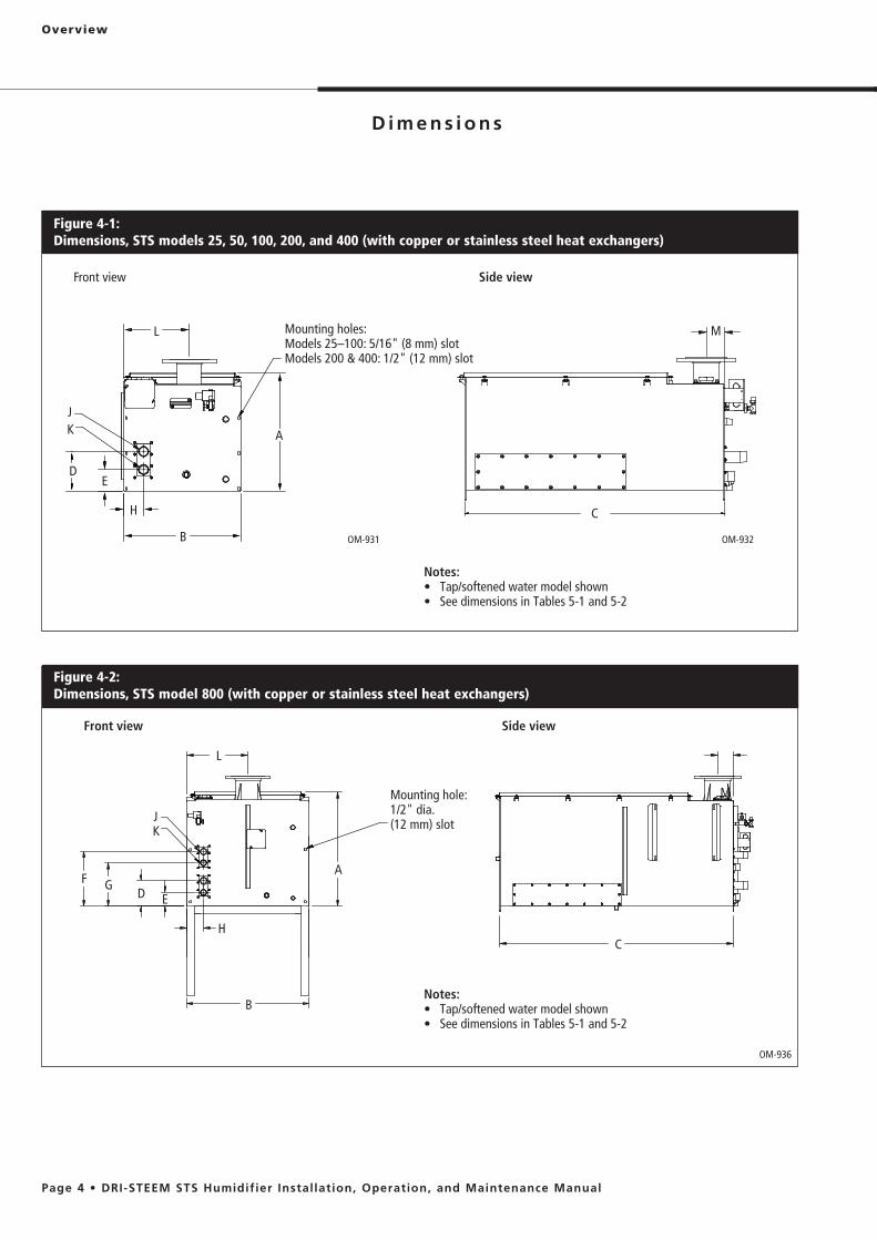
Figure 4-2: Dimensions, STS model 800 (with copper or stainless steel heat exchangers)
Front view
OM-936
Side view
Front view Side view
Figure 4-1:Dimensions, STS models 25, 50, 100, 200, and 400 (with copper or stainless steel heat exchangers)
Mounting holes:Models 25–100: 5/16" (8 mm) slotModels 200 & 400: 1/2" (12 mm) slot
B
A
E
H
D
C
OM-932OM-931
JK
L M
B
E
F
CH
G
J
A
D
L
K
MMounting hole:1/2" dia. (12 mm) slot
Notes:
Notes:

Overview
Table 5-2:Dimensions, STS with stainless steel heat exchangers
Description
See drawings in Figures 4-1 and 4-2
STS model*
25S 50S 100S 200S 400SNC 800SNC
inches mm inches mm inches mm inches mm inches mm inches mm
A Height** 19.50 495 19.50 495 19.50 495 19.50 495 19.50 495 29.75 756
B Width 14.75 375 14.75 375 19.25 489 30.25 768 30.25 768 30.25 768
C Length 23.65 600 39.65 1007 39.65 1007 55.15 1401 55.15 1401 55.15 1401
D Bottom to supply inlet of first heat exchanger 6.85 174 6.85 174 6.85 174 6.85 174 6.85 174 6.85 174
E Bottom to return outlet of first heat exchanger 3.35 85 3.35 85 3.35 85 3.35 85 3.35 85 3.35 85
F Bottom to supply inlet of second heat exchanger — — — — — — — — — — 14.5 368
G Bottom to return outlet of second heat exchanger — — — — — — — — — — 11.0 279
H Side to heat exchanger 3.25 83 3.25 83 3.25 83 3.25 83 3.25 83 3.25 83
J Pressurized steam supply inlet 3/4" pipe thread DN20 1" pipe
thread DN25 1" pipe thread DN25 1½" pipe
thread DN40 1½" pipe thread DN40 1½" pipe
thread DN40
K Pressurized steam return outlet 3/4" pipe thread DN20 3/4" pipe
thread DN20 3/4" pipe thread DN20 3/4" pipe
thread DN20 3/4" pipe thread DN20 3/4" pipe
thread DN20
L Side to steam outlet 6.25 159 8.63 219 9.63 245 13.00 330 13.00 330 13.00 330
M Front to steam outlet 2.50 64 2.25 57 2.75 70 3.75 95 3.75 95 3.75 95
* C, S, and SNC in model numbers are explained in “Heat exchangers and water types” on Page 6.** Add 23.5" (597 mm) to overall height when STS is mounted on four support legs. Add 22.5" (572 mm) to overall height when STS is mounted on two H-legs.
Table 5-1:Dimensions, STS with copper heat exchangers
Description
See drawings in Figures 4-1 and 4-2
STS model*
25C 50C 100C 400C 800C
inches mm inches mm inches mm inches mm inches mm
A Height** 19.50 495 19.50 495 19.50 495 19.50 495 29.75 756
B Width 14.75 375 14.75 375 19.25 489 30.25 768 30.25 768
C Length 23.65 600 39.65 1007 39.65 1007 55.15 1401 55.15 1401
D Bottom to supply inlet of first heat exchanger 6.63 168 6.63 168 6.63 168 6.63 168 6.63 168
E Bottom to return outlet of first heat exchanger 3.63 92 3.63 92 3.63 92 3.63 92 3.63 92
F Bottom to supply inlet of second heat exchanger — — — — — — — — 14.28 363
G Bottom to return outlet of second heat exchanger — — — — — — — — 11.24 285
H Side to heat exchanger 3.25 83 3.25 83 3.25 83 3.25 83 3.25 83
J Pressurized steam supply inlet 3/4" pipe thread DN20 1¼" pipe
thread DN32 1¼" pipe thread DN32 1½" pipe
thread DN40 1½" pipe thread DN40
K Pressurized steam return outlet 3/4" pipe thread DN20 3/4" pipe
thread DN20 1¼" pipe thread DN32 1¼" pipe
thread DN32 1¼" pipe thread DN32
L Side to steam outlet 6.25 159 8.63 219 9.63 245 13.00 330 13.00 330
M Front to steam outlet 2.50 64 2.25 57 2.75 70 3.75 95 3.75 95
* C, S, and SNC in model numbers are explained in “Heat exchangers and water types” on Page 6.** Add 23.5" (597 mm) to overall height when STS is mounted on four support legs. Add 22.5" (572 mm) to overall height when STS is mounted on two H-legs.
Overview
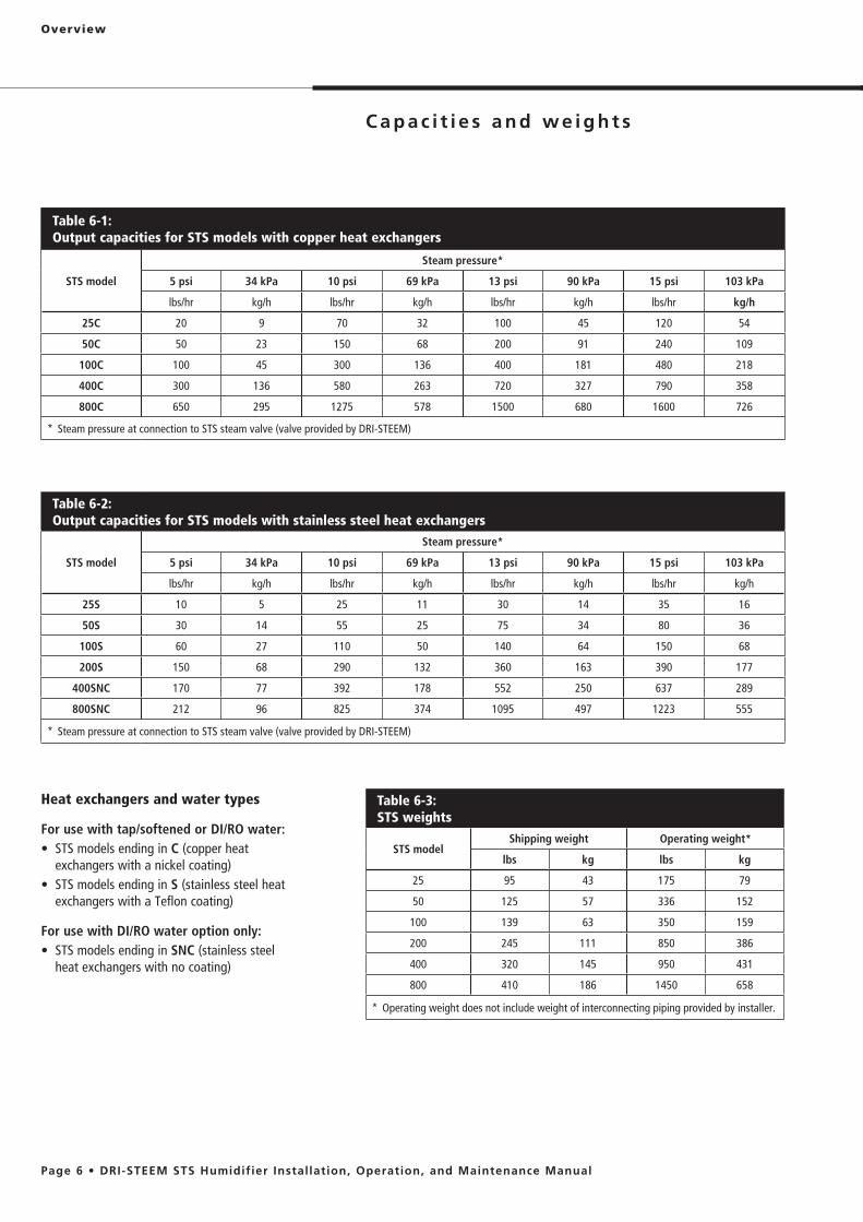
Table 6-1: Output capacities for STS models with copper heat exchangers
STS model
Steam pressure*
5 psi 34 kPa 10 psi 69 kPa 13 psi 90 kPa 15 psi 103 kPa
lbs/hr kg/h lbs/hr kg/h lbs/hr kg/h lbs/hr kg/h
25C 20 9 70 32 100 45 120 54
50C 50 23 150 68 200 91 240 109
100C 100 45 300 136 400 181 480 218
400C 300 136 580 263 720 327 790 358
800C 650 295 1275 578 1500 680 1600 726
* Steam pressure at connection to STS steam valve (valve provided by DRI-STEEM)
Table 6-2: Output capacities for STS models with stainless steel heat exchangers
STS model
Steam pressure*
5 psi 34 kPa 10 psi 69 kPa 13 psi 90 kPa 15 psi 103 kPa
lbs/hr kg/h lbs/hr kg/h lbs/hr kg/h lbs/hr kg/h
25S 10 5 25 11 30 14 35 16
50S 30 14 55 25 75 34 80 36
100S 60 27 110 50 140 64 150 68
200S 150 68 290 132 360 163 390 177
400SNC 170 77 392 178 552 250 637 289
800SNC 212 96 825 374 1095 497 1223 555
* Steam pressure at connection to STS steam valve (valve provided by DRI-STEEM)
Heat exchangers and water types
For use with tap/softened or DI/RO water:C (copper heat
exchangers with a nickel coating)S (stainless steel heat
exchangers with a Teflon coating)
For use with DI/RO water option only:SNC (stainless steel
heat exchangers with no coating)
Table 6-3:STS weights
STS modelShipping weight Operating weight*
lbs kg lbs kg
25 95 43 175 79
50 125 57 336 152
100 139 63 350 159
200 245 111 850 386
400 320 145 950 431
800 410 186 1450 658
* Operating weight does not include weight of interconnecting piping provided by installer.
Overview
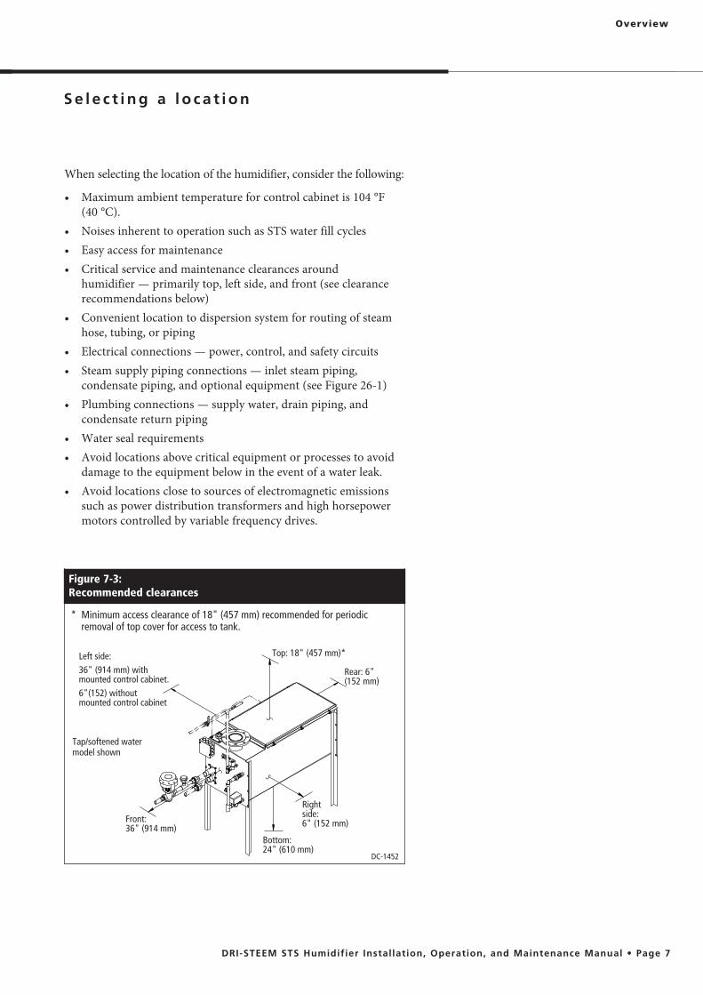
When selecting the location of the humidifier, consider the following:
aximum ambient temperature for control cabinet is 104 °F (40 °C).
humidifier — primarily top, left side, and front (see clearance recommendations below)
hose, tubing, or piping
condensate piping, and optional equipment (see Figure 26-1)
condensate return piping
damage to the equipment below in the event of a water leak.
such as power distribution transformers and high horsepower motors controlled by variable frequency drives.
Figure 7-3:Recommended clearances
DC-1452
Top: 18" (457 mm)*
Rear: 6" (152 mm)
Right side: 6" (152 mm)
Bottom: 24" (610 mm)
Front: 36" (914 mm)
* Minimum access clearance of 18" (457 mm) recommended for periodic removal of top cover for access to tank.
Left side:36" (914 mm) with mounted control cabinet.6"(152) without mounted control cabinet
Tap/softened water model shown
Installation
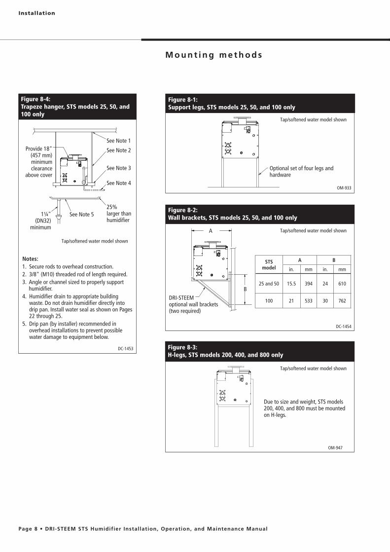
OM-933
Figure 8-1:Support legs, STS models 25, 50, and 100 only
Optional set of four legs and hardware
Figure 8-4:Trapeze hanger, STS models 25, 50, and 100 only
OM-947
Figure 8-3:H-legs, STS models 200, 400, and 800 only
DRI-STEEM optional wall brackets (two required)
B
A
DC-1454
Figure 8-2:Wall brackets, STS models 25, 50, and 100 only
STS model
A B
in. mm in. mm
25 and 50 15.5 394 24 610
100 21 533 30 762
Due to size and weight, STS models 200, 400, and 800 must be mounted on H-legs.
Tap/softened water model shown
Tap/softened water model shown
Tap/softened water model shown
Notes:1. Secure rods to overhead construction.2. 3/8" (M10) threaded rod of length required.3. Angle or channel sized to properly support
humidifier.4. Humidifier drain to appropriate building
waste. Do not drain humidifier directly into drip pan. Install water seal as shown on Pages 22 through 25.
5. Drip pan (by installer) recommended in overhead installations to prevent possible water damage to equipment below.
Provide 18" (457 mm) minimum clearance
above cover
DC-1453
See Note 1
See Note 2
See Note 3
See Note 4
25% larger than humidifier
1¼" (DN32)
minimum
See Note 5
Tap/softened water model shown

Installation
Table 9-1:STS mounting options
Mounting method
STS model
25, 50, 100 200, 400, 800
Trapeze hanger standard —
H-legs — standard
Support legs optional —
Wall brackets optional —
I m p o r t a n t :
Installation must comply with local governing codes.
These mounting methods are the only options available to maintain compliance to the UL 998 standard. Alternate mounting methods will compromise the humidifier’s CE, ETL, and C-ETL approval.
Support legs, trapeze hanger, and wall brackets are not available for STS models 200, 400, and 800.
The STS humidifier tank must be level from side to side and front to back. For all mounting methods, shim and adjust when mounting, and verify that tank is level after it is filled and at operating weight.
Support legs
See Figure 8-1. Use the enclosed bolts, nuts, and washers to fasten the legs to the tank.
Wall brackets
See Figure 8-2. DRI-STEEM does not recommend mounting STS model 200, 400, or 800 with wall brackets. DRI-STEEM recommends using 3/8" (M10) fasteners.
Concrete or block wall: Use concrete anchors (expansion bolts) rated for the operating weight of the STS humidifier. Position the wall brackets so they are flush with the front and back flanges of the tank.Wood stud wall: Mount two horizontal 2 � 4 boards (100 mm � 50 mm timbers) 16" (404 mm) on center:– STS 25: Lag bolt (coach screw) the 2 � 4s to two studs.– STS 50: Lag bolt the 2 x 4s to three studs.– STS 100: Lag bolt the 2 x 4s to four studs.Lag bolt the wall brackets to the horizontal 2�� 4s. Position the wall brackets flush with front and back flanges of tank.Metal stud wall: Follow the wood stud wall guidelines above, but provide a second set of 2 � 4s (100 mm � 50 mm timbers) on the backside of the wall. Run bolts with washers through the face 2 � 4, through each metal stud, and through the backside 2 � 4. Fasten the bolts and the face and backside 2 x 4s to the wall with washers and nuts.
H-legs
See Figure 8-3. With the STS tank securely held in place above the floor, attach front and rear supports using the supplied 3/8" (M10) bolts, nuts, and washers. Make sure the bottom of the tank is supported by the H -leg supports; this can be accomplished by having the bolts slightly loose as the unit is lowered to the floor, then tighten them after the unit is place.
Trapeze hanger
See Figure 8-4. Secure the threaded rods to an overhead structure strong enough to support the operating weight of the humidifier, field-installed piping, and (if mounted on the humidifier) control cabinet.
For overhead installations, install a drip pan to prevent possible damage to equipment below in the event of a water leak.

Installation
Figure 10-1: Weather cover exploded view
OM-7466
Table 10-2:Weather cover dimensions
Letter DescriptionSTS 25 to 100 STS 200 to 800
inches mm inches mm
A Height 62 1575 66 1676
B Length 43.5 1105 53 1346
C Width 62 1575 78.25 1988
D Distance from bottom 22 559 22 559
Figure 10-2: Weather cover dimensions
OM-7465
Table 10-1:Weather cover weights
Weather cover size lbs kg
STS 25 to 100 425 193
STS 200 to 800 550 250
D
BC
A
Panel
Hinged door
Panel
Panel
Panel
Hinged door

Installation
The optional STS weather cover is water-resistant and designed to protect an STS humidifier from rain and sun. This weather cover has been tested and approved by ETL Testing Laboratories,
The weather cover is fully assembled at the DRI-STEEM factory.
Installation notesOpen the hinged doors to make necessary connections to the humidifier. Refer to the installation section of this manual for all electrical, supply water, and drain connection requirements.Installation issues specific to weather cover applications
piping and electrical connections.
rated, watertight conduit.
ultraviolet rays will prematurely age the steam hose.
after making steam connection to maintain weather protection.
disconnection of the steam supply. This allows easy removal of the weather cover to access the STS for service and maintenance.
Annual weather cover maintenance requirements
Installation
Notes:
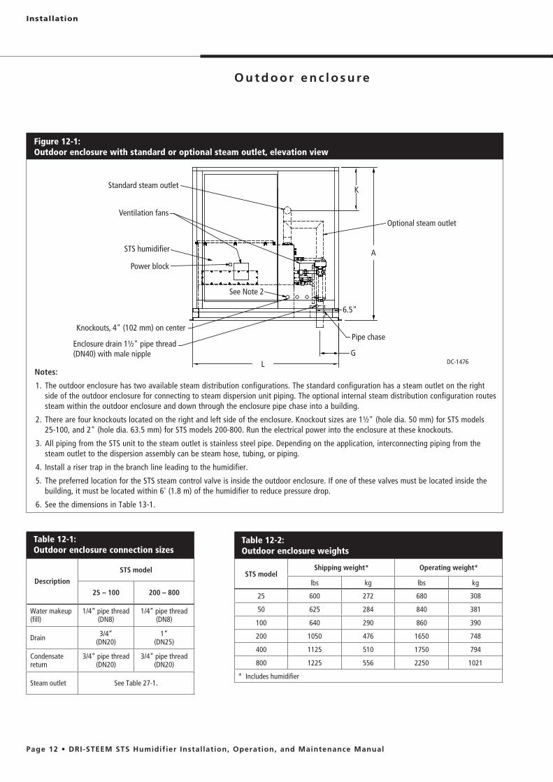
1. The outdoor enclosure has two available steam distribution configurations. The standard configuration has a steam outlet on the right side of the outdoor enclosure for connecting to steam dispersion unit piping. The optional internal steam distribution configuration routes steam within the outdoor enclosure and down through the enclosure pipe chase into a building.
2. There are four knockouts located on the right and left side of the enclosure. Knockout sizes are 1½" (hole dia. 50 mm) for STS models 25-100, and 2" (hole dia. 63.5 mm) for STS models 200-800. Run the electrical power into the enclosure at these knockouts.
3. All piping from the STS unit to the steam outlet is stainless steel pipe. Depending on the application, interconnecting piping from the steam outlet to the dispersion assembly can be steam hose, tubing, or piping.
4. Install a riser trap in the branch line leading to the humidifier.
5. The preferred location for the STS steam control valve is inside the outdoor enclosure. If one of these valves must be located inside the building, it must be located within 6' (1.8 m) of the humidifier to reduce pressure drop.
6. See the dimensions in Table 13-1.
Figure 12-1:Outdoor enclosure with standard or optional steam outlet, elevation view
Table 12-2:Outdoor enclosure weights
STS modelShipping weight* Operating weight*
lbs kg lbs kg
25 600 272 680 308
50 625 284 840 381
100 640 290 860 390
200 1050 476 1650 748
400 1125 510 1750 794
800 1225 556 2250 1021
* Includes humidifier
Table 12-1:Outdoor enclosure connection sizes
Description
STS model
25 – 100 200 – 800
Water makeup (fill)
1/4” pipe thread(DN8)
1/4” pipe thread(DN8)
Drain 3/4” (DN20)
1” (DN25)
Condensate return
3/4” pipe thread(DN20)
3/4” pipe thread(DN20)
Steam outlet See Table 27-1.
DC-1476
Ventilation fans
Power block
Knockouts, 4" (102 mm) on center
Enclosure drain 1½" pipe thread (DN40) with male nipple
Pipe chase
G
A
Standard steam outlet
Optional steam outlet
See Note 2
STS humidifier
L
K
6.5"
Installation
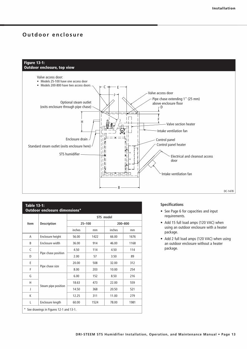
Table 13-1:Outdoor enclosure dimensions*
Item Description
STS model
25–100 200–800
inches mm inches mm
A Enclosure height 56.00 1422 66.00 1676
B Enclosure width 36.00 914 46.00 1168
CPipe chase position
4.50 114 4.50 114
D 2.00 57 3.50 89
EPipe chase size
20.00 508 32.00 312
F 8.00 203 10.00 254
G
Steam pipe position
6.00 152 8.50 216
H 18.63 473 22.00 559
J 14.50 368 20.50 521
K 12.25 311 11.00 279
L Enclosure length 60.00 1524 78.00 1981
* See drawings in Figures 12-1 and 13-1.
Figure 13-1:Outdoor enclosure, top view
DC-1478B
Standard steam outlet (exits enclosure here)
Intake ventilation fan
D
C
Pipe chase extending 1" (25 mm) above enclosure floor
STS humidifierElectrical and cleanout access door
Control panel heaterControl panelEnclosure drain
F
E
Optional steam outlet (exits enclosure through pipe chase)
Valve access door:
Intake ventilation fan
Valve section heater
Valve access doorJ
H
Specifications
requirements.
using an outdoor enclosure with a heater package.
an outdoor enclosure without a heater package.

Installation
Figure 14-1:Outdoor enclosure installation detail
Open to drain
Vacuum breaker (by installer)
Disconnect (by installer); see Detail A
120 V supply
Open drain(See Note 4)
Heated building interior
Normally open (fail open) min 1/2" electric valve (by installer)
Optional water seal (P-trap) drain line, min. 1½" (DN40) (See Note 3)
Roof deckingDetail A
120 V N
To valves (by installer) (See Note 1)
To STS humidifier
OM-7558
Drain line, min. 1½" electric valve (See Note 3)
Domestic water, 80 psig (582 kPa) maximum
Normally closed (fail closed) min 3/8" electric valve (by installer)
Normally closed fill valve (by factory)
Disconnect box
120 V from unit disconnect or other source (See Note 1)
Make-up water supply piping (by installer) (See Note 2)
Open drain(See Note 4)
Humidifier
Notes:1. Insulate supply water piping to avoid dripping from condensation. To ensure that water does not remain in the fill line and freeze if there
is a loss of power, DRI-STEEM recommends field installing additional valves upstream of the fill valve in a conditioned space. Power these valves on the same circuit that supplies the STS (as shown above); if the power goes off, water drains out of the fill line to prevent freezing.
2. Ensure that water lines are protected from freezing conditions.outdoor enclosure.
thermostat with a remote sensor on the fill line to cut power to the STS and safety valves to stop fill water to the STS and drain the fill piping when the temperature is below freezing.
3. DRI-STEEM recommends copper or iron drain piping for outdoor enclosures. On a loss of power the tank water will drain, but not be cooled by the Drane-kooler because of the field supplied safety shut-off valves. If it is critical to keep the Drane-kooler functional in the case of a power loss, disconnect the Drane-kooler and relocate it down inside the conditioned space of the building. Pipe the supply water for the Drane-kooler before the safety shut-off valves.
4. If copper or iron piping is used for both the fill and drain piping, these drains may be tied together. Locate 1" air gap only in spaces with adequate temperature and air movement to absorb flash steam; otherwise, condensation may form on nearby surfaces. Refer to governing codes for drain pipe size and maximum discharge water temperature.

Figure 15-1:STS outdoor enclosure, top view
DC-1478B
Standard steam outlet (exits enclosure here)
Intake ventilation fan
D
C
Pipe chase extending 1" (25 mm) above enclosure floor
STS humidifier Electrical and cleanout access door
Control panel heaterControl panelEnclosure drain
E
Optional steam outlet (exits enclosure through pipe chase)
Valve access door:
Intake ventilation fan
Valve section heater
Valve access doorJ
H
Installation
F
Mounting
clearance to open access doors.
enclosure, and that support structure dimensions coincide with unit dimensions.
gasoline storage, or other contaminants that could potentially cause dangerous situations. Using or storing gasoline or other flammable vapors and liquids in open containers in vicinity of outdoor enclosure is hazardous.
minimum of 14" (356 mm) above roof to prevent intake of snow or splashed rain. Position outdoor enclosure so prevailing winds do not blow into air intakes.
installing the unit.
may have become loosened. Check that all nuts are tightened.
Important note about STS outdoor enclosure installation
the humidifier.
control valve is inside the outdoor enclosure. If one of these valves must be located inside the building, it must be located within 6' (1.8 m) of the humidifier to reduce pressure drop.
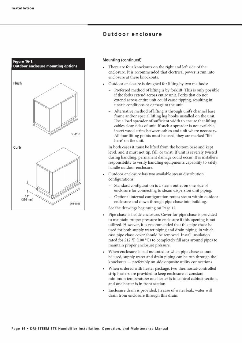
Figure 16-1:Outdoor enclosure mounting options
DC-1110
Flush
14" (356 mm)
OM-1095
Curb
Installation
Mounting (continued)
enclosure. It is recommended that electrical power is run into enclosure at these knockouts.
– Preferred method of lifting is by forklift. This is only possible if the forks extend across entire unit. Forks that do not extend across entire unit could cause tipping, resulting in unsafe conditions or damage to the unit.
– Alternative method of lifting is through unit’s channel base frame and/or special lifting lug hooks installed on the unit. Use a load spreader of sufficient width to ensure that lifting cables clear sides of unit. If such a spreader is not available, insert wood strips between cables and unit where necessary. All four lifting points must be used; they are marked “lift here” on the unit.
In both cases it must be lifted from the bottom base and kept level, and it must not tip, fall, or twist. If unit is severely twisted during handling, permanent damage could occur. It is installer’s responsibility to verify handling equipment’s capability to safely handle outdoor enclosure.
configurations:– Standard configuration is a steam outlet on one side of
enclosure for connecting to steam dispersion unit piping.– Optional internal configuration routes steam within outdoor
enclosure and down through pipe chase into building. See the drawings beginning on Page 12.
to maintain proper pressure in enclosure if this opening is not utilized. However, it is recommended that this pipe chase be used for both supply water piping and drain piping, in which case pipe chase cover should be removed. Install insulation rated for 212 °F (100 °C) to completely fill area around pipes to maintain proper enclosure pressure.
be used, supply water and drain piping can be run through the knockouts — preferably on side opposite utility connections.
strip heaters are provided to keep enclosure at constant minimum temperature: one heater is in control cabinet section, and one heater is in front section.
drain from enclosure through this drain.

Installation
Mounting (continued)
in contact with strip heaters or block intake ventilation hood.
in a severe climate, a remote-mount keypad/display should be installed. Additional cable lengths up to 500 feet (152 m) are available as an option for this mounting configuration.
unassembled for ease of transporting to roof; they include all hardware for bolt-together assembly, and all holes are matched before leaving factory. Curb must be a minimum of 14" (356 mm) high. One 2" × ½" closed-cell curb gasket with adhesive on one side is supplied with hardware. Gasket must be installed between top of curb and base surface of outdoor enclosure to prevent moisture from leaking into building from driving rain or melting snow. Installation drawing is included.
pipe. Depending on application, interconnecting piping from steam outlet to dispersion assembly can be tubing, pipe or DRI-STEEM steam hose.
STS outdoor enclosure sequence of operation
50 °F (10 °C), the strip heaters power up. Strip heaters remain on until enclosure reaches 50 °F (10 °C) to ensure that enclosure temperature does not drop below the freezing point.
aquastat maintains tank temperature at the factory default of 70 °F (21 °C). This temperature can be reset in the field to be from 40 to 180 °F (4 to 82 °C).
enclosure reaches 85 °F (29 °C), two ventilation fans turn on to cool the electronic components. A high limit is also provided to power down the STS if the enclosure temperature reaches 150 °F (66 °C). In a high limit situation, the ventilation fans continue to run and once the enclosure temperature falls below 130 °F (54 °C), the STS automatically resumes normal operation.
the STS outdoor enclosure to drain the tank in the event of a power loss.
OM-7464
Figure 17-1:Typical rooftop installation overview
OM-955
Figure 17-3:Outdoor enclosure clearances
Left side: 36" (914 mm)
Top: Keep open
Back: 12" (305 mm)
Right side: 24" (610 mm)
Front: 36" (914 mm)
Steam piping
Roof surface
Curb
Water piping
Remote Vapor-logic4
keypad
Electrical connections
Drain piping
Humidifier in outdoor enclosure
Installation
The drain line piped from the humidifier must be run to an approved sanitary waste or suitable drain. If nonmetallic pipe or steam hose is used, it must be rated for 212 °F (100 °C) minimum continuous operating temperature.Minimum drain pipe sizes:
pipe size. If combining multiple drain lines, ensure that proper common pipe sizing practices are used.
Do not locate the humidifier directly above a floor drain — skim and drain water dumped into the floor drain will cause flash steam. This steam will rise and saturate electrical components, adversely affecting component life and performance.
Tempering drain water Governing codes may require that the 212 °F (100 °C) drain and skim water from the humidifier be tempered before it is discharged into the building drain piping. The Drane-kooler® option will temper 6 gpm (22.7 L/m) of 212 °F (100 °C) water to 140 °F (60 °C).
Water seal To allow normal operation and prevent steam from escaping through the drain line, the installer must provide a water seal of a sufficient height to contain the pressure developed in the humidifier system. See Table 27-1 for water seal heights.Drain piping after the water seal must be pitched a minimum of 1/8"/ft (1%) toward the drain. Governing codes may require more pitch.
Condensate pump If the proximity of a drain requires the humidifier drain and skim water to be lifted by a pump, DRI-STEEM offers a condensate pump option. A check valve is required on the discharge of the pump. Electrical power for the pump is independent of the humidifier. Plug the pump into a wall outlet; an integral float switch turns the pump on and off.
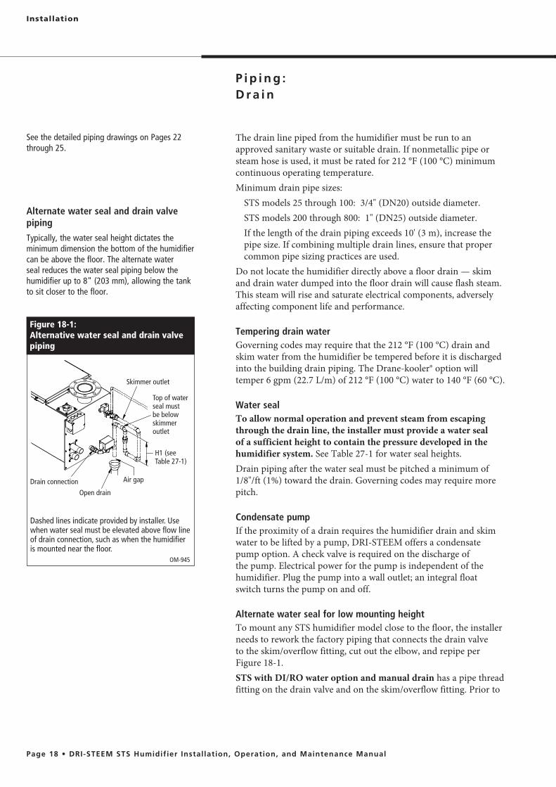
Alternate water seal for low mounting height To mount any STS humidifier model close to the floor, the installer needs to rework the factory piping that connects the drain valve to the skim/overflow fitting, cut out the elbow, and repipe per Figure 18-1. STS with DI/RO water option and manual drain has a pipe thread fitting on the drain valve and on the skim/overflow fitting. Prior to
Figure 18-1: Alternative water seal and drain valve piping
Dashed lines indicate provided by installer. Use when water seal must be elevated above flow line of drain connection, such as when the humidifier is mounted near the floor.
Skimmer outlet
Open drain
Air gapDrain connection
H1 (see Table 27-1)
Top of water seal must be below skimmer outlet
OM-945
Alternate water seal and drain valve piping
Typically, the water seal height dictates the minimum dimension the bottom of the humidifier can be above the floor. The alternate water seal reduces the water seal piping below the humidifier up to 8" (203 mm), allowing the tank to sit closer to the floor.
See the detailed piping drawings on Pages 22 through 25.
Installation
dumping into a drain, the installer needs to connect the drain and skim/overflow, provide a water seal of height H1 (see Table 22-1), and pipe. .
Drain connection Note: This section applies to all tap/softened water STS models and
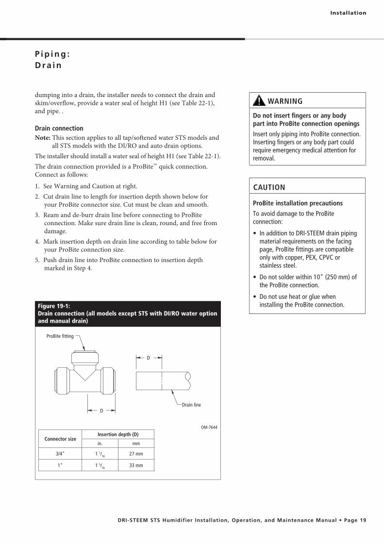
all STS models with the DI/RO and auto drain options. The installer should install a water seal of height H1 (see Table 22-1). The drain connection provided is a ProBite™ quick connection. Connect as follows:
1. See Warning and Caution at right. 2. Cut drain line to length for insertion depth shown below for
your ProBite connector size. Cut must be clean and smooth.3. Ream and de-burr drain line before connecting to ProBite
connection. Make sure drain line is clean, round, and free from damage.
4. Mark insertion depth on drain line according to table below for your ProBite connection size.
5. Push drain line into ProBite connection to insertion depth marked in Step 4.
Figure 19-1: Drain connection (all models except STS with DI/RO water option and manual drain)
OM-7644
WARNING
Do not insert fingers or any body part into ProBite connection openings
Insert only piping into ProBite connection. Inserting fingers or any body part could require emergency medical attention for removal.
CAUTION
ProBite installation precautions
To avoid damage to the ProBite connection:
material requirements on the facing page, ProBite fittings are compatible only with copper, PEX, CPVC or stainless steel.
the ProBite connection.
installing the ProBite connection.
ProBite fitting
Drain lineD
D
Connector sizeInsertion depth (D)
in. mm
3/4" 1 1/16 27 mm
1" 1 5/16 33 mm

Water supply piping All STS humidifier models have a 1" (25 mm) internal air gap to prevent back siphoning into a potable water system. However, some governing codes may require additional protection such as a vacuum breaker or backflow preventer.The supply water pressure range must be 25 to 80 psi (172 to 552 kPa).
Tap/softened water STS Water supply assembly includes a strainer, needle valve, and fill
the primary component of the water supply assembly is a solenoid valve, there may be noise issues that surface during a fill cycle.During a fill cycle, the supply water drops the water temperature in the tank and may collapse the steam, which can cause a low rolling sound. To diminish this, adjust the needle valve to decrease the water fill rate and/or use hot supply water.In cases where water hammer occurs when the fill solenoid closes, a shock arrester is recommended. Reducing the supply water pressure (minimum 25 psi [172 kPa]) or using flexible tubing (rated 212 °F [100 °C], minimum continuous operating temperature) may diminish the noise, but installing a shock arrester is the best solution. The minimum water conductivity for the probe-type water level control system to work is 30 μS/cm.
Installation

STS with DI/RO water option A float valconnection. European models are provided with a 3/8" pipe thread
valve is added on the inlet of the float valve. This option shuts off the fill water supply and drains the tank when there is no demand for humidity for 72 hours. (This is a default setting, which is adjustable. To modify this value, see the Vapor-logic4 Installation and Operation Manual.)When using nonmetallic tubing for supply water, it must be rated for 212 °F (100 °C) minimum continuous operating temperature. DRI-STEEM recommends installing a three-foot (914 mm) piece of noninsulated stainless steel pipe directly off the humidifier prior to connecting to the nonmetallic tubing. When using nonmetallic tubing, DRI-STEEM recommends the installer place a 2" (50 mm) water seal/loop in the supply line to isolate steam during DI/RO water system maintenance.DRI-STEEM recommends installing a strainer in the water supply line to prevent clogging of the float valve orifice. A strainer is highly recommended when the humidifier has the end-of-season drain option. The strainer will prevent particulate from collecting at the solenoid valve seat.If an STS humidifier with the DI/RO water option is supplied with tap water, the float valve assembly will become clogged and run without water.
Installation
Installation
DC-1451
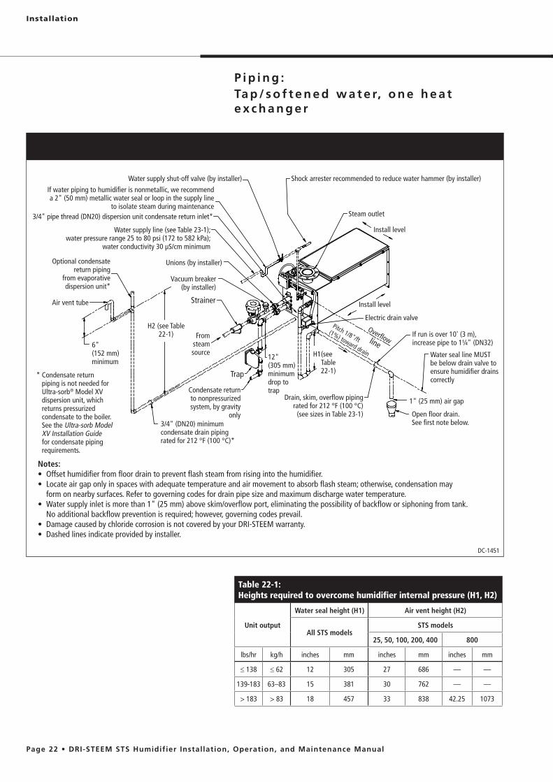
Notes:
form on nearby surfaces. Refer to governing codes for drain pipe size and maximum discharge water temperature.
No additional backflow prevention is required; however, governing codes prevail.
Table 22-1:Heights required to overcome humidifier internal pressure (H1, H2)
Unit output
Water seal height (H1) Air vent height (H2)
All STS modelsSTS models
25, 50, 100, 200, 400 800
lbs/hr kg/h inches mm inches mm inches mm
��138 ��62 12 305 27 686 — —
139-183 63–83 15 381 30 762 — —
> 183 > 83 18 457 33 838 42.25 1073
Optional condensate return piping
from evaporative dispersion unit*
Air vent tube
3/4" (DN20) minimum condensate drain piping rated for 212 °F (100 °C)*
Strainer
Unions (by installer)
Water supply shut-off valve (by installer) Shock arrester recommended to reduce water hammer (by installer)
Steam outlet
Install level
Install level
Electric drain valveOverflowline
Trap
If run is over 10' (3 m), increase pipe to 1¼" (DN32)
Water seal line MUST be below drain valve to ensure humidifier drains correctly
1" (25 mm) air gap
Open floor drain. See first note below.
Drain, skim, overflow piping rated for 212 °F (100 °C)
(see sizes in Table 23-1)
6" (152 mm) minimum
Vacuum breaker (by installer)
Condensate return to nonpressurized system, by gravity
only
12" (305 mm) minimum drop to trap
If water piping to humidifier is nonmetallic, we recommend a 2" (50 mm) metallic water seal or loop in the supply line
to isolate steam during maintenance
Water supply line (see Table 23-1); water pressure range 25 to 80 psi (172 to 582 kPa);
water conductivity 30 μS/cm minimum
H2 (see Table 22-1) From
steam source H1 (see
Table 22-1)* Condensate return
piping is not needed for Ultra-sorb® Model XV dispersion unit, which returns pressurized condensate to the boiler. See the Ultra-sorb Model XV Installation Guide for condensate piping requirements.
Pitch 1/8"/ft (1%) toward drain
3/4" pipe thread (DN20) dispersion unit condensate return inlet*

Installation
Figure 23-1:Field piping overview for tap/softened water STS model 800
DC-1467
Optional condensate return piping from
dispersion unit*
Air vent tube
H2 (see Table 22-1)
Strainers (by installer)
Steam outlet
Install level
Install level
Electric drain valve
Overflowline
Traps If run is over 10' (3 m), increase pipe to 1¼" (DN32)
1" (25 mm) air gapOpen floor drain. See first note below
Unions (by installer)
Water seal line MUST be below drain valve to ensure humidifier drains correctly
6" (152 mm) minimum
Water supply line (see Table 23-1); water pressure range 25 to 80 psi (172 to 582 kPa);
water conductivity 30 μS/cm minimum
3/4" (DN20) minimum condensate drain piping rated for 212 °F (100 °C)*
Condensate return to nonpressurized
system, by gravity only
12" (305 mm) minimum drop to traps
Vacuum breakers (by installer)
Notes:
may form on nearby surfaces. Refer to governing codes for drain pipe size and maximum discharge water temperature.
tank. No additional backflow prevention is required; however, governing codes prevail.
H1 (see Table 22-1)
Table 23-1:STS connection sizes
Description Connection size
Water makeup (fill) 1/4" pipe thread (DN8), all STS models
Drain 3/4" (DN20) for STS models 25 through 1001" (DN25) for STS models 200 through 800
Steam outlet Varies with capacity and dispersion type; see Table 33-1
Condensate return 3/4" pipe thread (DN20)
Pressurized steam supply inlet and return outlet See sizes in Tables 5-1 and 5-2.
Water supply shut-off valve (by installer)
Shock arrestor (by installer) recommended to eliminate water hammer
3/4" pipe thread (DN20) dispersion unit condensate return inlet*
Drain, skim, overflow
piping rated for 212 °F
(100 °C) (see sizes in Table 23-1)
From steam source
Pitch 1/8"/ft (1%) toward drain
* Condensate return piping is not needed for Ultra-sorb® Model XV dispersion unit, which returns pressurized condensate to the boiler. See the Ultra-sorb Model XV Installation Guide for condensate piping requirements.
Installation
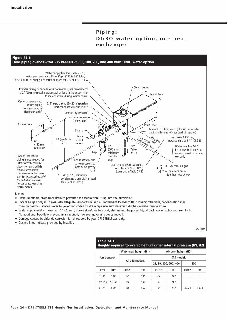
Figure 24-1:Field piping overview for STS models 25, 50, 100, 200, and 400 with DI/RO water option
Optional condensate return piping
from evaporative dispersion unit*
Air vent tube
3/4" (DN20) minimum condensate drain piping rated for 212 °F (100 °C)*
Strainer
Unions (by installer)
Steam outlet
Install level
Install level
Overflowline
Trap
If run is over 10' (3 m), increase pipe to 1¼" (DN32)
Water seal line MUST be below drain valve to ensure humidifier drains correctly
1" (25 mm) air gap
Open floor drain. See first note below.
Drain, skim, overflow piping rated for 212 °F (100 °C)
(see sizes in Table 25-1)
DC-1459
6" (152 mm) minimum
Notes:
form on nearby surfaces. Refer to governing codes for drain pipe size and maximum discharge water temperature.
No additional backflow prevention is required; however, governing codes prevail.
Vacuum breaker (by installer)
Condensate return to nonpressurized system, by gravity
only
12" (305 mm) minimum drop to trap
If water piping to humidifier is nonmetallic, we recommend a 2" (50 mm) metallic water seal or loop in the supply line
to isolate steam during maintenance
Water supply line (see Table 25-1); water pressure range 25 to 80 psi (172 to 582 kPa);
first 3' (1 m) of supply line must be rated for 212 °F (100 °C)
H2 (see Table 12-1)
From steam source
H1 (see Table 24-1)
Pitch 1/8"/ft (1%) toward drain
3/4" pipe thread (DN20) dispersion unit condensate return inlet*
Manual SST drain valve (electric drain valve available for end-of-season drain option)
Table 24-1:Heights required to overcome humidifier internal pressure (H1, H2)
Unit output
Water seal height (H1) Air vent height (H2)
All STS modelsSTS models
25, 50, 100, 200, 400 800
lbs/hr kg/h inches mm inches mm inches mm
��138 ��62 12 305 27 686 — —
139-183 63–83 15 381 30 762 — —
> 183 > 83 18 457 33 838 42.25 1073
* Condensate return piping is not needed for Ultra-sorb® Model XV dispersion unit, which returns pressurized condensate to the boiler. See the Ultra-sorb Model XV Installation Guide for condensate piping requirements.
Installation
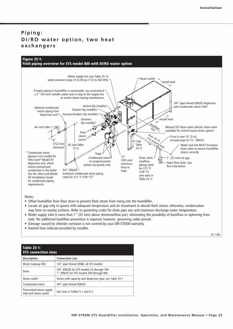
Figure 25-1:Field piping overview for STS model 800 with DI/RO water option
DC-1468
Optional condensate return piping from
dispersion unit*
Air vent tube
H2 (see Table 12-1)
Strainers (by installer)
Steam outletInstall level
Install levelOverflowline
Traps
If run is over 10' (3 m), increase pipe to 1¼" (DN32)
1" (25 mm) air gap
Open floor drain. See first note below
Unions (by installer)
Water seal line MUST be below drain valve to ensure humidifier drains correctly
6" (152 mm) minimum
Water supply line (see Table 25-1); water pressure range 25 to 80 psi (172 to 582 kPa);
3/4" (DN20) minimum condensate drain piping rated for 212 °F (100 °C)*
Condensate return to nonpressurized
system, by gravity only
12" (305 mm) minimum drop to traps
Vacuum breakers (by installer)
Notes:
may form on nearby surfaces. Refer to governing codes for drain pipe size and maximum discharge water temperature.
tank. No additional backflow prevention is required; however, governing codes prevail.
H1 (see Table 24-1)
3/4" pipe thread (DN20) dispersion unit condensate return inlet*
Drain, skim, overflow piping rated for 212 °F (100 °C) (see sizes in Table 25-1)
From steam source
Pitch 1/8"/ft (1%) toward drain
If water piping to humidifier is nonmetallic, we recommend a 2" (50 mm) metallic water seal or loop in the supply line
to isolate steam during maintenance
Strainer (by installer)
Manual SST drain valve (electric drain valve available for end-of-season drain option)
Table 25-1:STS connection sizes
Description Connection size
Water makeup (fill) 1/4" pipe thread (DN8), all STS models
Drain 3/4" (DN20) for STS models 25 through 1001" (DN25) for STS models 200 through 800
Steam outlet Varies with capacity and dispersion type; see Table 33-1
Condensate return 3/4" pipe thread (DN20)
Pressurized steam supply inlet and return outlet See sizes in Tables 5-1 and 5-2
* Condensate return piping is not needed for Ultra-sorb® Model XV dispersion unit, which returns pressurized condensate to the boiler. See the Ultra-sorb Model XV Installation Guide for condensate piping requirements.

Figure 26-1:Steam supply piping to STS humidifier
Steam main
Alternate vacuum breaker position
12"
12"
Vacuum breaker (by installer)
Gravity condensate return
End of branch trap
(by installer)Swing check valves (by installer) OM-941
Steam trap, required for proper operation (by DRI-STEEM)
The heat exchanger in the STS humidifier is designed for a maximum steam pressure of 15 psi (105 kPa). The steam valve, trap, and strainer are shipped loose for field installation.Figure 26-1 shows piping from an overhead steam supply main with condensate returned to a vented gravity flow return system.
the steam valve of the STS. Failure to install this trap will cause water hammer, which could damage the STS heat exchanger.
from the heat exchanger when the steam valve closes.Lifting condensate with pressurized steam is not recommended. Premature heat exchanger failure and erratic control can occur when using pressurized steam to lift condensate. A steam condensate pump is recommended when lifting condensate in a pressurized system.
Note:
For STS 800 models, to guarantee steam output capacities, a dedicated steam valve and steam trap is required for each heat exchanger.
Installation

Installation
Figure 27-2:2-inch hose connection
DC-1455
Figure 27-3:2-inch threaded pipe connection
DC-1456
Figure 27-4:2-inch tubing or hard pipe connection using hose cuff with clamps
DC-1456
Figure 27-1:Flange connection
DC-1458
Dashed lines indicate provided by installer
Steam hose
Steam outlet connection (tubing)
Hose clamp
Tap/softened water model shown
Dashed lines indicate provided by installer
* Support pipe from above to prevent excessive weight on humidifier outlet. Allow for thermal expansion.
Threaded pipe*
Pipe union
Steam outlet connection (threaded pipe nipple)
Tap/softened water model shown
Dashed lines indicate provided by installer
Hose clamps
Tubing or pipe
6" (152 mm) long hose cuffSteam outlet connection (tubing)
Tap/softened water model shown
Steam outlet connection (flange)
Support memberSupport piping from above to prevent excessive weight on humidifier outlet. Allow for thermal expansion.
Tap/softened water model shown
Table 27-1:STS steam outlet sizes and types
STS model
Pipe thread size Hose size Flange size
DN50 (2")
DN50 (2")
DN80 (3")
DN100 (4")
DN125 (5")
DN150 (6")
25 X X
50 X X X
100 X X X X
200 X X X X
400 X X X X
800 X X X
Installation
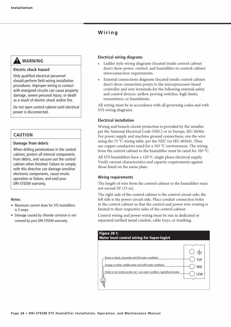
Figure 28-1: Water level control wiring for Vapor-logic4
Brown or black, top probe rod (full water condition)
Orange or white, middle probe rod (refill water condition)
Violet or red, bottom probe rod: Low water condition, tap/softened water
TOP
MID
LOW
Electrical wiring diagrams
style wiring diagrams (located inside control cabinet door) show power, control, and humidifier-to-control-cabinet interconnection requirements.
door) show connection points to the microprocessor-based controller and wire terminals for the following external safety and control devices: airflow proving switches, high limits, transmitters, or humidistats.
All wiring must be in accordance with all governing codes and with STS wiring diagrams.
Electrical installation
Wiring and branch circuit protection is provided by the installer
For power supply and machine ground connections, size the wire
use copper conductors rated for a 105 °C environment. The wiring from the control cabinet to the humidifier must be rated for 105 °C.
those listed on the name plate.
Wiring requirements
The length of wire from the control cabinet to the humidifier must
The right side of the control cabinet is the control circuit side; the left side is the power circuit side. Place conduit connection holes in the control cabinet so that the control and power wire routing is limited to their respective sides of the control cabinet.Control wiring and power wiring must be run in dedicated or separated earthed metal conduit, cable trays, or trunking.
Notes:
is 3 amps.
covered by your DRI-STEEM warranty.
CAUTION
Damage from debris
When drilling penetrations in the control cabinet, protect all internal components from debris, and vacuum out the control cabinet when finished. Failure to comply with this directive can damage sensitive electronic components, cause erratic operation or failure, and void your DRI-STEEM warranty.
WARNING
Electric shock hazard
Only qualified electrical personnel should perform field wiring installation procedures. Improper wiring or contact with energized circuits can cause property damage, severe personal injury, or death as a result of electric shock and/or fire.
Do not open control cabinet until electrical power is disconnected.

The control cabinet should be mounted in a location convenient for service with a minimum of 36" (914 mm) clearance in front of the door.The installer is responsible for making electrical connections at the power terminals.
Control wiring
The following wiring methods for external low-voltage control wiring should minimize electrical noise problems:
distat, RH transmitter, and temperature transmitter wiring must be minimum 18-gauge (1 mm2) plenum rated, shielded (screened), twisted pair wire with a bare drain wire for grounding.
(1 mm2) stranded wire run in conduit. The airflow proving switch can be wired using minimum 18-gauge (1 mm2) plenum rated, shielded (screened), twisted pair wire with a bare drain wire for grounding.
(screen) ground terminal/lug with a length less than 2" (51 mm). Do not ground the shield (screen) wire on the humidistat or transmitter end.
must be minimum 18-gauge stranded wire run in a separate
2)
m), use 18-gauge (1 mm2) plenum rated, shielded (screened), twisted pair wire with a bare drain wire for grounding.
Grounding requirements
The approved earth ground must be made with solid metal-to-metal connections and must be a good conductor of radio frequency interference (RFI) to earth (multistranded conductors).Ground wire should be the same AWG (mm2) size as the power
requirements).When the control cabinet is mounted remotely from the humidifier, a ground wire is necessary from the machine ground lug on the humidifier to the machine ground lug in the control cabinet. The bonding machine ground wire should be no less than 14-gauge AWG (mm2
I m p o r t a n t : Failure to follow these wiring procedures can result in erratic operation or failure.
This product has been tested at the factory for proper operation. Product failures resulting from faulty handling, incorrect wiring, or shorting of wires together on external components are not covered under your DRI-STEEM warranty. Review information and diagrams before proceeding.
Installation

Installation
Humidistat and transmitter locations are criticalHumidistat and humidity transmitter locations have a significant impact on humidifier performance. DRI-STEEM recommends that you do not interchange duct and room humidity devices. Room humidity devices are calibrated with zero or little airflow; whereas duct humidity devices require air passing across them. See the following recommendations and the locations in Figure 30-1.A Ideal humidistat or humidity transmitter location. Placement
here ensures the best uniform mix of dry and moist air with stable temperature control.
B Acceptable, but the room environment can affect controllability such as when the humidistat or transmitter is too close to air grilles, registers, or heat radiation from room lighting.
C Acceptable, because this location provides a uniform mixture of dry and moist air. If there is a time lag between humidity generation and sensing, extend the sampling time.
D Acceptable behind a wall or partition for sampling the entire room, if the sensor is near an air exhaust return outlet. Typical humidistat or transmitter placement for sampling a critical area.
overall conditions in the space.
windows, door passageways, or areas of stagnant airflow.G Best sensing location for a high limit humidistat or humidity
transmitter and airflow proving switch.
Figure 30-1:Recommended humidistat and transmitter locations
Outside air
Relief air Return air Air handling unit
8' to 12'(2.4 m to 3.7 m)
minimum
Humidifier dispersion assembly
Turning vanes
WindowDoorway
Window
Point of vapor absorption
Vapor absorption has taken place
Airflow switch or differential pressure switch (sail type recommended for VAV applications)
High limit humidistat or high limit transmitter (set at 90% RH maximum) for VAV applications
Damper control
C
A
E
F
D
B
E F
G
F
DC-1084M
Wall or partition

Installation
DRI-STEEM humidifiers operate with several types of dispersion assemblies for open spaces and for ducts and air handling units. Dispersion assemblies in ducts and air handling units must be positioned where the water vapor being discharged is carried off with the airstream and is absorbed before it can cause condensation or dripping.
required for non-wetting to occur. For more information about absorption non-wetting distances, see the non-wetting tables in
or ordering at www.dristeem.com.
air can absorb the moisture being added without causing condensation at or after the unit. This normally will be after the heating coil or where the air temperature is highest.
absorption will occur– before the intake of a high efficiency filter, because the filter
can remove the visible moisture and become waterlogged;– before coming in contact with any metal surface;– before fire or smoke detection devices;– before a split in the duct; otherwise, the dispersion assembly
can direct more moisture into one duct than the other.
a 1" (25 mm) air gap between the condensate drain piping and the drain. Locate the gap only in spaces with adequate temperature and air movement to absorb flash steam; otherwise, condensation may form on nearby surfaces.
I m p o r t a n t :Failure to follow the recommendations in this section can result in excessive back pressure on the humidifier. This will result in unacceptable humidification system performance such as leaking gaskets, blown water seals, erratic water level control, and spitting condensate from the dispersion tube.

Installation
High-efficiency Tube option
Dispersion assemblies with the High-efficiency Tube option are designed to produce significantly less dispersion-generated condensate and airstream heat gain, which reduces wasted energy by up to 85%. These improvements are accomplished by reducing the thermal conductivity of the tubes with 1/8" of polyvinylidene fluoride (PVDF) insulating material on the outside of the tubes. These assemblies require careful unpacking, installation, and handling. If your dispersion assembly has the High-efficiency Tube option, be sure to read this section carefully.
Figure 32-1:Ultra-sorb with the High-efficiency Tube option
WARNING
Hot surface and steam hazard
Dispersion tube, steam hose, tubing, or hard pipe can contain steam, and surfaces can be hot. Discharged steam is not visible. Contact with hot surfaces or air into which steam has been discharged can cause severe personal injury.
The steam outlet on the humidifier is sized to the output of
tubing/piping with an inside diameter smaller than the humidifier steam outlet. See note on facing page.
assembly, use the recommended installation shown in Figure 34-1.
Connecting to humidifier with steam hose
to maintain a minimum pitch of 2"/ft (15%) back to the humidifier.
hose may use unacceptable release agents or material mixes that can affect humidifier system performance adversely. Using hose from alternative manufacturers increases the possibility of tank foaming and accelerated aging. Foaming causes condensate discharge at the dispersion assembly.
aging, causing the steam hose to become hard and susceptible to failure due to cracks.
Connecting to humidifier with tubing or pipe
requirements for single tube and multiple tube applications. See Table 41-1 for interconnecting tubing and pipe pitch requirements for Rapid-sorb applications.
outlet and the dispersion system with pipe hangers. Failure to properly support the entire steam piping weight may cause damage to the humidifier tank and void the warranty.
adapters convert a tubing outlet on the humidifier to threaded pipe, allowing a pipe connection.
apart.
than heavy wall pipe.
condensation.
lubricants used to thread the pipe. This will minimize the possibility of tank foaming. Denatured alcohol or mineral spirits work best for removing lubricant.
Installation
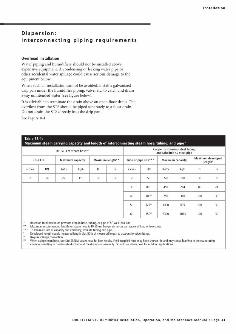
Table 33-1: Maximum steam carrying capacity and length of interconnecting steam hose, tubing, and pipe*
DRI-STEEM steam hose††† Copper or stainless steel tubing and Schedule 40 steel pipe
Hose I.D. Maximum capacity Maximum length** Tube or pipe size*** Maximum capacity Maximum developed length†
inches DN lbs/hr kg/h ft m inches DN lbs/hr kg/h ft m
2 50 250 113 10 3 2 50 220 100 30 9
3†† 80†† 450 204 80 24
4†† 100†† 750 340 100 30
5†† 125†† 1400 635 100 30
6†† 150†† 2300 1043 100 30
* Based on total maximum pressure drop in hose, tubing, or pipe of 5" wc (1244 Pa)** Maximum recommended length for steam hose is 10' (3 m). Longer distances can cause kinking or low spots.*** To minimize loss of capacity and efficiency, insulate tubing and pipe.† Developed length equals measured length plus 50% of measured length to account for pipe fittings.†† Requires flange connection.††† When using steam hose, use DRI-STEEM steam hose for best results. Field-supplied hose may have shorter life and may cause foaming in the evaporating
chamber resulting in condensate discharge at the dispersion assembly. Do not use steam hose for outdoor applications.
Overhead installation Water piping and humidifiers should not be installed above expensive equipment. A condensing or leaking water pipe or other accidental water spillage could cause serious damage to the equipment below. When such an installation cannot be avoided, install a galvanized drip pan under the humidifier piping, valve, etc. to catch and drain away unintended water (see figure below).It is advisable to terminate the drain above an open floor drain. The overflow from the STS should be piped separately to a floor drain. Do not drain the STS directly into the drip pan.See Figure 8-4.

Install a drip tee as shown below when the humidifier is mounted higher than the dispersion assembly, when interconnecting hose or piping needs to go over an obstruction, or when interconnecting piping runs are long.I m p o r t a n t : Steam hose must be supported to prevent sagging or low spots.
Installation
Figure 34-1:Drip tee installation (piping over an obstruction)
DC-1470
STS humidifier
Funnel or floor drain
¾" (DN20)
1" (25 mm) air gap
8" (200 mm) minimum
6" (150 mm) minimum
To dispersion device
Insulate tubing and hard pipe to reduce steam loss
90° long sweep or two 45° elbows
Obstruction
Pitch
Tubing or pipe drip tee, by installer.DRI-STEEM part number for 304 stainless steel in-line tee:2" diameter (DN50): No. 162712
Notes:
nearby surfaces. Refer to governing codes for drain pipe size and maximum discharge water temperature.

Installation
Table 35-1:Single tube hose kit sizing by capacity
Maximum tube capacity Hose kit
(steam hose, dispersion tube, and hardware)lbs/hr kg/h
56.8 25.8 2" (DN50) without drain
85.2 38.6 2" (DN50) with drain
> 85.2 >38.6
These models require multiple tube assemblies and cannot use a single hose kit.
I m p o r t a n t :Failure to follow the recommendations in this section can result in excessive back pressures on the humidifier. This will result in unacceptable humidification system performance such as leaking gaskets, blown water seals, erratic water level control, and spitting condensate from the dispersion tube(s).
Dispersion tube mounting
up.
tube(s), see drip tee installation in Figure 34-1.
Condensate drain piping
continuous operating temperature.
on the following pages. Provide a 6" (152 mm) drop prior to a 5" (127 mm) water seal to:− Ensure drainage of condensate from the header
a 1" (25 mm) vertical air gap. Cut the drain line at a 45° angle on the end above the drain to permit a direct stream of water into the drain pipe while maintaining a 1" (25 mm) air gap. Locate air gap only in spaces with adequate temperature and air movement to absorb flash steam, or condensing on nearby surfaces may occur.
governing codes.

Installation
B
B
90° long sweep or two 45° elbows
STS humidifier Secure and seal duct escutcheon plate
Pitch*
Maximum capacity of dispersion tube:
Tube pitch 2"/ft (15%)
3/8" (M10) mounting nut
Duct
Figure 36-1:Single tube dispersion without condensate drain
Dashed lines indicate provided by installer
* Pitch steam hose, tubing or pipe toward humidifier:
– 2"/ft (15%) when using steam hose – 1/8"/ft (1%) when using tubing or pipe
OM-7512
Single dispersion tube without condensate drain
Dispersion tube escutcheon plate
Steam hose, tubing or pipe. Insulate tubing and hard
pipe to reduce steam loss. Do not insulate steam hose.
Table 36-1: Dispersion tube escutcheon plate dimensions
for 2" tube
inches mm
A 2.03 52
B 5.00 127
Table 36-2: Pitch of dispersion tube(s) and interconnecting piping for Single tube or multiple tube evaporative dispersion units*
Condensate drain Type ofinterconnecting piping
Diameter ofdispersion tube and
interconnecting piping
Pitch ofinterconnecting piping
Pitch ofdispersion tube(s)
Pitch ofcondensate drain
Without drain
Steam hose 2" (DN50) 2"/ft (15%)toward humidifier
2"/ft (15%) toward humidifier No drain
Tubing or pipe 2" (DN50) 1/8"/ft (1%)toward humidifier
With drain
Steam hose 2" (DN50) 2"/ft (15%) toward humidifier 1/8"/ft (1%)
towardcondensate
drain
¼"/ft (2%)toward floor drain or toward humidifier if humidifier is below
dispersion unitTubing or pipe 2" (DN50) ¼"/ft (2%)toward humidifier
* When piping over an obstruction, see the drip tee installation illustration on Page 38.
A(diameter)
Installation
Dispersion tube plate
Condensate drain plate
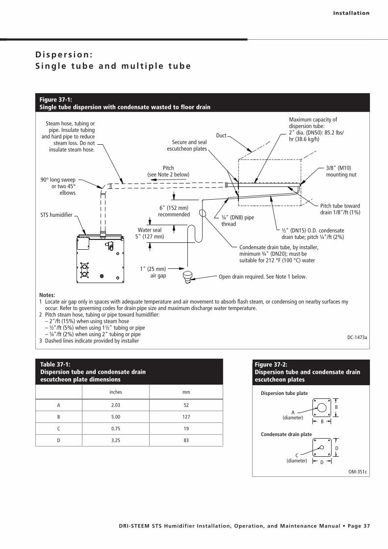
Figure 37-2:Dispersion tube and condensate drain escutcheon plates
Steam hose, tubing or pipe. Insulate tubing
and hard pipe to reduce steam loss. Do not
insulate steam hose.
90° long sweep or two 45°
elbows
STS humidifier6" (152 mm)
recommended
Water seal 5" (127 mm)
Pitch(see Note 2 below)
1" (25 mm) air gap Open drain required. See Note 1 below.
Condensate drain tube, by installer, minimum ¾" (DN20); must be suitable for 212 °F (100 °C) water
½" (DN15) O.D. condensate drain tube; pitch ¼"/ft (2%)
Pitch tube toward drain 1/8"/ft (1%)
3/8" (M10) mounting nut
Maximum capacity of dispersion tube: 2" dia. (DN50): 85.2 lbs/hr (38.6 kg/h)
Duct
¼" (DN8) pipe thread
Figure 37-1:Single tube dispersion with condensate wasted to floor drain
Notes:1 Locate air gap only in spaces with adequate temperature and air movement to absorb flash steam, or condensing on nearby surfaces my
occur. Refer to governing codes for drain pipe size and maximum discharge water temperature.2 Pitch steam hose, tubing or pipe toward humidifier: – 2"/ft (15%) when using steam hose – ½"/ft (5%) when using 1½" tubing or pipe – ¼"/ft (2%) when using 2" tubing or pipe3 Dashed lines indicate provided by installer
DC-1473a
OM-351c
Table 37-1: Dispersion tube and condensate drain escutcheon plate dimensions
inches mm
A 2.03 52
B 5.00 127
C 0.75 19
D 3.25 83
B
D
B
D
A(diameter)
C(diameter)
Secure and seal escutcheon plates
Installation
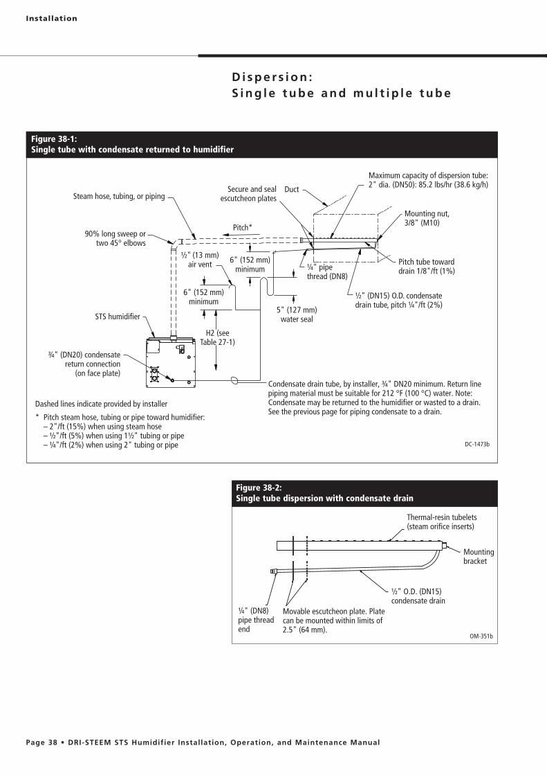
Figure 38-1: Single tube with condensate returned to humidifier
STS humidifier
Duct
½" (DN15) O.D. condensate drain tube, pitch ¼"/ft (2%)
¾" (DN20) condensate return connection
(on face plate)
H2 (see Table 27-1)
5" (127 mm) water seal
DC-1473b
6" (152 mm) minimum
½" (13 mm) air vent
6" (152 mm) minimum
90% long sweep or two 45° elbows
Steam hose, tubing, or piping
Pitch*
¼" pipe thread (DN8)
Figure 38-2:Single tube dispersion with condensate drain
OM-351b
Mounting bracket
Thermal-resin tubelets (steam orifice inserts)
Movable escutcheon plate. Plate can be mounted within limits of 2.5" (64 mm).
¼" (DN8) pipe thread end
½" O.D. (DN15) condensate drain
Condensate drain tube, by installer, ¾" DN20 minimum. Return line piping material must be suitable for 212 °F (100 °C) water. Note: Condensate may be returned to the humidifier or wasted to a drain. See the previous page for piping condensate to a drain.
Mounting nut, 3/8" (M10)
Pitch tube toward drain 1/8"/ft (1%)
Maximum capacity of dispersion tube:2" dia. (DN50): 85.2 lbs/hr (38.6 kg/h)
Dashed lines indicate provided by installer
* Pitch steam hose, tubing or pipe toward humidifier: – 2"/ft (15%) when using steam hose – ½"/ft (5%) when using 1½" tubing or pipe – ¼"/ft (2%) when using 2" tubing or pipe
Secure and seal escutcheon plates

Installation
Figure 39-1: Multiple tube with condensate wasted to floor drain
Duct
STS humidifier
½" (DN15) O.D. condensate drain tube, pitch ¼"/ft (2%)
Condensate drain tube provided by installer, ¾" (DN20) minimum
Water seal 5" (127 mm)
90° long sweep or two 45° elbows
6" (152 mm)
1" (25 mm)air gap
¼" pipe thread (DN8)
DC-1048a
Pitch tube toward drain 1/8"/ft (1%)
Steam hose, tubing, or piping
Pitch*
Maximum capacity of dispersion tube:2" dia. (DN50): 85.2 lbs/hr (38.6 kg/h)
Mounting nut, 3/8" (M10)
Open drain required.Locate air gap only in spaces with adequate temperature and air movement to absorb flash steam; otherwise, condensation may form on nearby surfaces. Refer to governing codes for drain pipe size and maximum discharge water temperature.
Dashed lines indicate provided by installer
* Pitch steam hose, tubing or pipe toward humidifier: – 2"/ft (15%) when using steam hose – ½"/ft (5%) when using 1½" tubing or pipe – ¼"/ft (2%) when using 2" tubing or pipe
Secure and seal escutcheon plates

Installation
Read all dispersion instructions in this manual, and follow the installation instructions below:
components with packing list. Report any shortages to DRI-STEEM immediately. The components typically include the following:– Multiple dispersion tubes– Header– ¾" × 2" (19 mm × 51 mm) L-bracket
Note: Dispersion tubes, header, and L-bracket are each tagged with the customer requested identification number.
– A single duct escutcheon plate the size of the header– Slip couplings or hose cuffs and clamps– Accessories such as duct plates, slip couplings, or hose cuffs– Bolts and washers for mounting the dispersion tubes to the
bracket
– L-bracket 50" (1270 mm) long or shorter has a mounting hole 4" (102 mm) from each end for mounting the L-bracket to the duct or air handler wall.
– L-bracket longer than 50" (1270 mm) has an additional mounting hole in the center.
Note: Hardware for mounting the L-bracket to the duct or air handler wall and the hardware for the header support bracket is not provided.
and around the ductwork or air handler.
duct, or is installed across the face of a coil in an air handler.
closer than 4.5" (114 mm) from the side of the ductwork or air handler wall.The following instructions are for a typical Rapid-sorb installation — horizontal-airflow duct with Rapid-sorb header either inside or outside the duct. See the Dri-calc Installation Guides library or contact your representative/distributor or DRI-STEEM for installation instructions for air handler or vertical airflow applications.
CAUTIONOperate Rapid-sorb within rated steam capacity
Excessive steam flow to the Rapid-sorb steam dispersion assembly can cause condensate to exit the tubelets, which can cause water damage and standing water in the duct or air handler.
To avoid condensate exiting the tubelets, do not operate the Rapid-sorb beyond its rated capacity.
I m p o r t a n t : Before marking and drilling holes in the duct or air handler, refer to ALL pitch requirements for the Rapid-sorb assembly you received (see Table 41-1). The size, quantity, and location of penetrations are determined by the dimensions and configuration of the Rapid-sorb assembly you received.

Installation
Pitch requirements
horizontal-airflow duct, consider the following:
length to accommodate the 1/8"/ft (1%) pitch requirements
flush to the ductwork. The 1/8"/ft (1%) pitch typically can be accomplished in the length of the hose cuffs used to connect the tubes to the header.
pitch requirements.
Table 41-2:Rapid-sorb dispersion tube capacities
Tube capacity Tube diameter
lbs/hr kg/h inches DN
≤ 35 ≤ 16 1½ 40
36-70 17-32 2 50
Table 41-3:Rapid-sorb header capacities
Header capacity Header diameter
lbs/hr kg/h inches DN
≤ 250 ≤ 113 2 50
251-500 114-227 3 80
501-800 228-363 4 100
801-1300 364-591 5 125
1301-2100 592-955 6 150
Table 41-1:Pitch of interconnecting piping, dispersion tubes, and headers for Rapid-sorb evaporative dispersion units
Airflow Type ofinterconnecting piping
Diameter ofinterconnecting piping
Pitch ofinterconnecting piping
Pitch of dispersion tubes
Pitch ofheader
Horizontal
Steam hose 1½" (DN40), 2" (DN50)2"/ft (15%)
towardRapid-sorb Vertically
plumb
1/8"/ft (1%)toward
condensatedrainTubing or pipe
1½" (DN40), 2" (DN50), 3" (DN80), 4" (DN100), 5" (DN125), 6" (DN150)
1/8"/ft (1%)toward
Rapid-sorb
Vertical
Steam hose 1½" (DN40), 2" (DN50)2"/ft (15%)
towardRapid-sorb 2"/ft
towardheader
1/8"/ft (1%)toward
condensatedrainTubing or pipe
1½" (DN40), 2" (DN50), 3" (DN80), 4" (DN100), 5" (DN125), 6" (DN150)
1/8"/ft (1%)toward
Rapid-sorb

Figure 42-1:Rapid-sorb installed in a horizontal airflow with header outside the duct
STS humidifier
DC-1471
6" (152 mm)
Duct
5" (127 mm)
AirflowDispersion tube
Slip coupling or hose cuff
90° long sweep or two 45° elbows
Support bracketSteam hose, tubing,
or piping
¾" pipe thread (DN20) condensate drain
¾" (DN20) copper
1" (25 mm) air gap
Position L-bracket so that flange is upstream of dispersion tubes. This drawing shows the L-bracket
positioned for airflow back to front
Point tubelets (steam orifices) perpendicular to airflow
Pitch*
* Pitch steam hose, tubing, or pipe toward Rapid-sorb:
– 2"/ft (15%) when using steam hose
– 1/8"/ft (1%) when using tubing or pipe
Pitch header toward drain 1/8"/ft (1%)
Open drain required. Locate air gap only in spaces with adequate temperature and air movement to absorb flash steam; otherwise, condensation may form on nearby surfaces. Refer to governing codes for drain pipe size and maximum discharge water temperature.
Installation
Header outside of duct, horizontal airflow
1. Mark and cut holes in the ductwork for the dispersion tubes. Use the L-bracket as a template to mark the holes on the duct floor.
2. Temporarily, loosely suspend or support the header below
tube length dictates where the header should be suspended or temporarily supported.
3. Mount the dispersion tubes to the header with the slip coupling or hose cuff (provided).
tubes, take care not to shear the O-rings.
the O-ring is resting on the face of the tubing.
lubricant.

Installation
Note:
See Page 46 for steam supply and condensate drain line connection instructions.
4. Position the flange of the L-bracket so it is upstream of the tubes when the assembly is raised and fastened into position. Fasten the L-bracket to the end of the dispersion tubes with the provided bolt, lock washer, and flat washer.
5. Before tightening the L-bracket bolts to the dispersion tubes:
dispersion tube orifices are directed perpendicular to airflow.
– Dispersion tube and slip coupling must be fully engaged on header stub for O-rings to provide a seal.
Before securing hose cuff in place with hose clamps on dispersion tube and the header stub, verify that dispersion tube orifices are directed perpendicular to airflow.
6. Slide the assembly up until the L-bracket aligns with the mounting holes in the duct.
– Header pitch is duplicated in the L-bracket. – Dispersion tube and slip coupling must be fully engaged
on header stub for O-rings to provide a seal. – High end of L-bracket can be fastened tight to duct or
air handler. – Fastener on low end of L-bracket must be long enough
to compensate for pitch. Use a nut on both sides of L-bracket and duct or air handler for stability.
– Fasten bracket to top of duct and use hose cuffs to compensate for header pitch.
– Before securing hose cuffs with hose clamps on dispersion tube and header stub, verify that header pitch, 1/8"/ft (1%) toward drain, is maintained.
7. Permanently secure both ends of header, and verify that header pitch, 1/8"/ft (1%) toward drain, is maintained.
9. Secure and seal the dispersion tube escutcheon plate and condensate drain tube escutcheon plate around the respective tubes, if applicable.

Figure 44-1:Rapid-sorb installed in a horizontal airflow with header inside the duct
DC-1472
6" (152 mm)
Duct
Steam hose, tubing, or piping
STS humidifier
AirflowDispersion tube
Slip coupling or hose cuff90° long sweep or
two 45° elbowsSupport bracket
5" (127 mm)
Position L-bracket so that flange is upstream of dispersion tubes. This drawing shows the L-bracket positioned for
airflow back to front
Point tubelets (steam orifices) perpendicular to airflow
Pitch*
* Pitch steam hose, tubing, or pipe toward Rapid-sorb:
– 2"/ft (15%) when using steam hose
– 1/8"/ft (1%) when using tubing or pipe
Open drain required. Locate air gap only in spaces with adequate temperature and air movement to absorb flash steam; otherwise, condensation may form on nearby surfaces. Refer to governing codes for drain pipe size and maximum discharge water temperature.
Installation
¾" pipe thread (DN20) condensate drain
¾" (DN20) copper
1" (25 mm) air gap
Pitch header toward drain 1/8"/ft (1%)
Header inside of duct, horizontal airflow
1. Mark and cut holes in ductwork or air handler for steam header penetration, condensate drain piping, and header support bracket fastener. Allow 1/8"/ft (1%) header pitch toward the support bracket when you drill the hole for the header support bracket fastener.
2. Loosely fasten the header in place. 3. Rotate the header 90° so the header stubs point horizontally in
the duct. When installing in an air handler, the rotation of the header is often less than 90°. Typically, due to the condensate drain piping requirements, the header can be set on the floor of the air handler, assembled in the vertical position, and then raised and mounted in place.
Installation
Note:
See Page 46 for steam supply and condensate drain line connection instructions.
4. Mount the dispersion tubes on the header with the slip couplings or hose cuffs:
tubes, take care not to shear O-rings.
is resting on face of tubing.
5. Allow the dispersion tubes to rest against the bottom of the duct.6. Position the flange of the L-bracket so it is upstream of the tubes
when the assembly is rotated into position. Fasten the L-bracket to the end of the dispersion tubes with the provided bolt, lock washer, and flat washer.
7. Rotate the assembly up until the L-bracket aligns with the mounting holes in the duct or air handler.
– Header pitch is duplicated in the L-bracket. – Dispersion tube and slip coupling must be fully engaged
on header stub for O-rings to provide a seal. – High end of L-bracket can be fastened tight to duct or
air handler. – Fastener on low end of L-bracket must be long enough
to compensate for pitch. Use a nut on both sides of L-bracket and duct or air handler for stability.
– Fasten bracket to top of duct and use hose cuffs to compensate for header pitch.
– Before securing hose cuffs with hose clamps on dispersion tube and header stub, verify that dispersion tube orifices are directed perpendicular to airflow.
9. Secure and seal the header escutcheon plate around the header.
Installation
Steam supply connections to Rapid-sorb headerConnect the steam supply interconnecting piping from the humidifier to the Rapid-sorb. The steam supply piping requires a minimum of 1/8"/ft (1%) pitch toward the header.If multiple humidifiers are supplying one Rapid-sorb, a multiple steam supply connector is provided. Typically, the multiple steam supply connector attaches to the Rapid-sorb header supply end with hose cuff and clamps:
1. Route the necessary number of steam supplies from the humidifier tanks to the steam supply connector.
2. Position the steam supply connector to accept the steam supplies while maintaining the necessary pitch.
3. Make sure the hose clamps on the steam supply connector and header are tight.
Condensate drain connections to Rapid-sorb header
(100 °C) minimum continuous operating temperature.The condensate drain line must be piped as shown in Figures 42-1 and 44-1. Provide a 6" (152 mm) drop prior to a 5" (127 mm) water seal to:
After the water seal, run the drain line to an open drain with a 1" (25 mm) vertical air gap.
to permit a direct stream of water into the drain pipe while maintaining a 1" (25 mm) air gap.
air movement to absorb flash steam, or condensing on nearby surfaces may occur.
All drain lines must be installed and sized according to governing codes.
Ultra-sorbFor Ultra-sorb steam dispersion panel instructions, see the installation, operation, and maintenance manual shipped with the Ultra-sorb.

Operation
After the system is installed and connected properly:
connections, steam supply, and dispersion unit(s) are installed according to the following:
Vapor-logic4 Installation and Operation Manual – Installation section– Pre-installation checklist
the humidifier are secure before applying power.
supported before filling with water. See operating weights in Table 6-1.
side after it is full of water.
5. Read the “Operation” section of the Vapor-logic4 Installation and Operation Manual.Note: During start-up, do not leave the humidifier unattended.
6. Perform all applicable “Start-up checklist” items. See Page 48.7. Monitor humidifier operation through multiple fill cycles. The
humidifier operating status appears on the keypad/display. 8. On tap/softened water units, water skims from the humidifier
after every fill cycle. Adjust the amount of skim by increasing or decreasing the skim time (see the Vapor-logic4 Installation and Operation Manual). At start-up, DRI-STEEM recommends initially running the humidifier with the factory default setting for skim time. See “Maintenance,” beginning on Page 49.
The Vapor-logic4 Installation and Operation Manual is a comprehensive operation manual. Refer to it for information regarding the following features:
The manual was shipped with your humidifier and is available at our Web site: www.dristeem.com
WARNING
Electric shock hazard
Only qualified electrical personnel should perform start-up procedure.
Contact with energized circuits can cause property damage, severe personal injury or death as a result of electrical shock or fire.
Make sure control cabinet door is in place and secure before turning on electrical power.

Operation
If an item in the Start-up checklist below does not apply to your system, skip to the next item and continue the process.☐ Read this manual and all other information that was provided
with your humidifier.☐
in this manual and in the humidifier wiring diagram.☐ Confirm that the input signal is consistent with the
Setup” in the Vapor-logic4 Installation and Operation Manual.☐ Confirm that proper grounding and an approved earth ground
are provided.☐ Confirm that the keypad/display is mounted with its modular
cable routed away from high-voltage circuits and connected to
☐ Turn on the water supply, and confirm that the drain valve is closed.
☐ Turn on power to the humidifier, and confirm the Main menu is displayed on the keypad/display. The display may take several seconds to appear as the controller powers up.
☐ Confirm in the Main Menu that the mode is “Auto” and that tank status is “Filling.”
☐ When “Filling” appears in main menu, confirm that the tank is filling with water.
☐ In the Status screen, confirm that the Duct Airflow Switch is closed.
☐ In the Status screen, confirm that the high limit humidistat input is closed or the high limit transmitter is connected.
☐ With sufficient water in the tank, the airflow switch closed, the high limit closed, the safety interlock closed, and the humidifier getting a call for humidity, verify that the steam valve is activated.
☐ If you experience difficulties, have the keypad/display information available along with the serial number and humidifier Model, and call DRI-STEEM Technical Support at 800-328-4447.

Maintenance
WARNING
Hot surface and hot water hazard
Do not touch the tank or drain piping until the unit has had sufficient time to cool, or serious injury can occur.
Opening the drain valve when the tank is hot can discharge water with a temperature up to 212 °F (100 °C) into the plumbing system. This can cause damage to the plumbing system if the humidifier is not properly connected to a water tempering device such as a DRI-STEEM Drane-kooler™.
The best way to determine how often your humidifier needs maintenance is to remove the tank cover and inspect it for mineral deposits after three months of duty. Hours of operation and duty cycle will determine your maintenance schedule, as will water quality.
Water quality and maintenanceMaintenance requirements vary with water quality, because tap and softened water carry a variety of minerals and other materials in a
content) water requires more frequent cleaning and drain/flush cycles than water with low mineral content.Softened water significantly reduces mineral accumulation inside the humidifier.Note: Solids, like silica, are not removed in the softening process.
Skim durationSkim duration determines the quantity of water skimmed with
keypad/display. Skimming reduces the need for frequent humidifier cleaning. Each time the tank refills, it fills to a level just above the lip of the skim/overflow fitting. A portion of the fill water flows out of the skim/overflow fitting to the drain, which flushes minerals left by the previous evaporating cycle and skims away surface residue.Both humidifier cleaning and heated water flowing to the drain are operational costs. DRI-STEEM recommends that the user observe and adjust the skim duration to achieve a balance between reducing mineral buildup and conserving heated water.mc_060210_1430
Humidifier De-scaling Solution
Scale buildup on humidifier heat exchangers acts as an insulator, reducing humidifier performance while increasing energy costs. To keep humidifiers operating as efficiently as possible, remove scale with DRI-STEEM's Humidifier De-scaling Solution, available for purchase from your DRI-STEEM representative or distributor.
The De-scaling Solution cleans without risk of corroding humidifier tanks or welds. The De-scaling Solution also cleans surfaces unreachable by hand scraping.
DRI-STEEM's Humidifier De-scaling Solution is the only approved cleaner/de-scaler for use with DRI-STEEM humidifiers. Use of other cleaners/de-scalers may void your DRI-STEEM warranty.

Cool down humidifier
Before performing any maintenance, allow the tank to cool down.Note: Fresh make-up water is used to speed up cooling. Do not
close the manual water supply before cooling down the humidifier; otherwise the tank could stay hot for several hours.
– For drain valves without the manual open lever, use the keypad to perform the cool down process. Refer to the Vapor-logic4 Installation and Operation Manual.
– Select Manual Drain in the control modes screen.– Allow approximately half the water to drain out of the tank.– Select Auto in the control modes screen; the fill valve opens
and the humidifier cools down.– When the fill valve closes, select Manual Drain in the
control modes screen and allow the tank to drain dry. The humidifier should be cool enough to work on.
Maintenance
CAUTIONHot discharge water
Discharge water can be as hot as 212 °F (100 °C) and can damage the drain plumbing.
To prevent such damage from humidifiers without water tempering, allow the tank to cool before draining.
Humidifiers equipped with a water tempering device such as a DRI-STEEM Drane-kooler need fresh make-up water in order to function properly. Make sure the water supply to the water tempering device remains open during draining.
Excessive supply water pressure
Supply water pressure greater than 80 psi (550 kPa) can cause the humidifier to overflow.
Troubleshooting
The Vapor-logic4 Installation and Operation Manual, which was shipped with your humidifier, is a comprehensive operation manual. Refer to it for troubleshooting information.

Inspection and maintenance
1. Annually (also recommended when maintenance is performed)
and off to verify they are functioning. These include:– High limit switch– Airflow proving switch– Low water level probe. Pull out probe plug; fill valve
should energize.
2. Seasonally (or as required, depending on water quality)
Cleaning the tank– Remove cleanout plate and dispose any loose scale that
has collected in the bottom of the tank. This should be done before the scale buildup reaches the bottom of the heat exchanger.
– Inspect the area inside the tank in front of the drain valve fitting, and thoroughly clean all scale and mineral buildup from that area.
Cleaning the probes– Disconnect the probe plug and cable assembly (located
on top of the tank), and unscrew the probe rod assembly from the humidifier probe housing using the probe tool (see Figure 51-1).
– Inspect the probe housing and clean, ensuring that all housing passageways are clear. To detach the housing from the tank, remove the four bolts that attach it to the tank. Then lift the housing up out of the tank.
– The scale should flake off easily from the probe assembly rods.
– The bottom 3/8" (10 mm) is the sensing portion of each probe rod; it should be brushed clean with a wire brush, abrasive pad, or steel wool.
– Inspect the composite plastic probe rod assembly for any signs of cracking, roughness, or deterioration. If found, replace probe assembly.
– Reassemble the probe rod assembly, and torque as indicated in Figure 51-1.
Maintenance
WARNING
Shutdown procedure
To prevent serious injury, follow this shutdown procedure before performing service or maintenance procedures on this humidifier (after the tank has cooled down and drained):
1. Use Vapor-logic4 keypad/display to change control mode to Standby.
2. Place all power disconnects in OFF position and lock in OFF position.
3. Close the field-installed manual water supply shut-off valve.
4. Close the manual shut-off valve on the inlet steam supply.
Figure 51-1:Probe tool
Remove and install probe assembly with supplied probe tool. Attach a 3/8" square drive to the probe tool.
When installing, torque probe assembly to 120 in-lbs (10 ft-lbs; 13.6 N-m). Probe tools can be ordered from your DRI-STEEM representative (Part no. 185101).
Probe tool
OM-7395X
Maintenance
– Water should drain from the skimmer drain pipe after each fill cycle. This should be verified visually by a weekly inspection.
– Loosen deposits in and around the skimmer overflow port with a long tool such as a screwdriver.
– Water should drain from the skimmer drain pipe after each fill cycle. This should be verified visually by a weekly inspection.
– Loosen deposits in and around the skimmer/overflow port with a long tool such as a screwdriver.
– If flow through the water seal/P-trap is diminished due to mineral accumulation: - Remove the water seal piping from the humidifier and
flush out.- Replace the water seal with new piping if the minerals
have hardened in the water seal.- Install a union at the base of the water seal to ease
removal if water quality causes the water seal to become clogged often with scale.
When the seasonal maintenance requirements are complete:cleanout plate, and torque the nuts to 25 to 35
plug and cable assembly are plugged into the probe rod holder.
cycle through multiple fill cycles and verify that the humidifier cover, cleanout plate, and probe holder gasket are not leaking.
3. Off-season maintenanceorm complete inspection and cleaning of the following:
– Heat exchanger– Probe rods– Skimmer port and water seal– Humidifier tank
a complete inspection and cleaning of the heat exchanger, skimmer, and water chamber. After cleaning, the unit should remain empty until humidification is required.

Maintenance
Regularly verify that water processing equipment is operating correctly. The presence of chlorides in improperly processed DI/RO water eventually causes pitting and failure of the heat exchanger, tank, and components. Your DRI-STEEM warranty does not cover damage caused by chloride corrosion.STS humidifiers with the DI/RO water option do not require cleaning, but regular inspections are advised. There are no skimming, drain, or flush cycles.
Cool down humidifierBefore performing any maintenance, allow the tank to cool down.Note: Fresh make-up water is used to speed up cooling. Do not
close the manual water supply before cooling down the humidifier; otherwise the tank could stay hot for several hours.
– Manually open the drain valve. The float valve opens.– Let the fill water run until the tank is cooled; then shut off
the field-installed manual supply water shut-off valve.– Let the tank drain; then manually close the drain valve.
– Use the keypad to perform the cool down process. Refer to the Vapor-logic4 Installation and Operation Manual.
– Select Manual Drain in the control modes screen.– Allow approximately half the water to drain out of the tank.– Select Auto in the control modes screen; the fill valve opens
and the humidifier cools down.– When the fill valve closes, select Manual Drain in the control
modes screen and allow the tank to drain completely dry. The humidifier should be cool enough to work on.
WARNING
Shutdown procedure
To prevent serious injury, follow this shutdown procedure before performing service or maintenance procedures on this humidifier (after the tank has cooled down and drained):
1. Use Vapor-logic4 keypad/display to change control mode to Standby.
2. Place all power disconnects in OFF position and lock in OFF position.
3. Close the field-installed manual water supply shut-off valve.
4. Close the manual shut-off valve on the inlet steam supply.
Maintenance
Inspection and maintenance
1. Annually (also recommended when maintenance is performed)
and off to verify they are functioning. These include:– High limit switch– Airflow proving switch
not shut off, there may be particulate on the valve seat, or the stopper may be worn and need replacing.
As long as mineral-free water is used in the humidifier, no cleaning or flushing should be necessary.
2. Off-season maintenance
– Heat exchanger– Float valve– Humidifier tank and gaskets
humidification is required.
a complete inspection and cleaning of the heat exchanger, skimmer, and water chamber. After cleaning, the unit should remain empty until humidification is required.
On units with Teflon coated heat exchangers, do not use a sharp object when cleaning. Cuts or scratches on the heat exchanger will impair its ability to shed scale during operation and could cause the Teflon to separate from the metal surface.
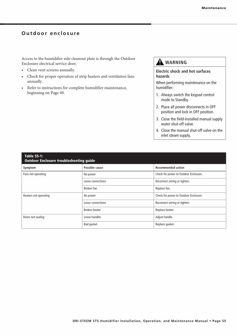
Maintenance
Access to the humidifier side cleanout plate is through the Outdoor Enclosure electrical service door.
annually.
beginning on Page 49.
WARNING
Electric shock and hot surfaces hazards
When performing maintenance on the humidifier:
1. Always switch the keypad control mode to Standby.
2. Place all power disconnects in OFF position and lock in OFF position.
3. Close the field-installed manual supply water shut-off valve.
4. Close the manual shut-off valve on the inlet steam supply.
Table 55-1:Outdoor Enclosure troubleshooting guide
Symptom Possible cause Recommended action
Fans not operating No power Check for power to Outdoor Enclosure.
Loose connections Reconnect wiring or tighten.
Broken fan Replace fan.
Heaters not operating No power Check for power to Outdoor Enclosure.
Loose connections Reconnect wiring or tighten.
Broken heater Replace heater.
Doors not sealing Loose handles Adjust handle.
Bad gasket Replace gasket.

Figure 56-1: Tank replacement parts
OM-946
Replacement parts

Table 57-1: Tank replacement parts
No. Description Part no.
1 Tank, STS Consult factory
2
Cover, STS-25 165341-001
Cover, STS-50 165341-002
Cover, STS-100 165341-003
Cover, STS-200/400/800 165341-004
3
Cover gasket, STS-25 160692-001
Cover gasket, STS-50 160692-002
Cover gasket, STS-100 160692-003
Cover gasket, STS-200/400/800 160692-004
4 Heat exchanger, STS Consult factory
5
Cleanout plate, STS-25 165481-001
Cleanout plate, STS-50/100 165481-002
Cleanout plate, STS-200/400/800 165481-003
6
Cleanout plate gasket, STS-25 308015-001
Cleanout plate gasket, STS-50/100 308015-002
Cleanout plate gasket, STS-800 505340
7 Fill assembly Consult factory
8*
Float fill assembly, STS-25/50/100 505315
Float fill assembly, STS-200/400 505305
Float fill assembly, STS-800 505340
9 Drain assembly Consult factory
10 Temperature sensor assembly 405760
11Probe assembly, STS-25/50/100/200/400 406303-008
Probe assembly, STS-800 406303-009
12 Probe gasket 309350-004
13* Probe plate 120370-020
14 Probe weld 165301
15 Probe plate/weld gasket 308416-001
16 Heat exchanger gasket, STS 308220
17 Heat exchanger mounting plate 164581-001
18 Junction box 407134-005/006
19 Condensate return plug 250192-075
20 Probe plug 406050-004
Components may be in different location or orientation than shown in drawing on previous page.
* STS with DI/RO water option only
Replacement parts

Figure 58-1: Control cabinet replacement parts
Note: Components may be in different location or orientation than shown in drawing.
OM-7646
15
12
10
5 6 5 7
9
11
4
14 3 1 2
13
12
16
17
Table 58-1: Control cabinet replacement parts*
No. Description Part no.
1 Control cabinet, 12 x 12 407100-003
2 Subpanel, STS 165720-002
3 Control board, Vapor-logic4 408495-001
4 Transformer, 120V to 24V 408965-001
5 Terminal block 408252-001
6 Ground terminal 408252-010
7 Terminal jumper 408252-009
8 Relay, 24V 3PDT, Finder 407900-017
9 DIN-rail end cap 408252-006
10 Terminal spacer 408252-005
11 DIN-rail, 6.5" (165 mm) 167765-006
12 Ground lug 409250-003
13 P-E switch 408100
14 Interlock switch 408470
15 Interlock switch bracket 165614
16 Vapor-logic4 keypad/display with back 408495-010
17 Vapor-logic4 keypad cable, 5' (1.5 m) 408490-009
* Specify humidifier model and serial numbers when ordering.
Replacement parts
8

Figure 59-1:Outdoor enclosure replacement parts
OM-953
Table 59-1: Outdoor enclosure replacement parts
Number in drawing Description Part number
1 500W strip heater 405800-052
2 1100W strip heater 405800-053
3 Cooling fan 405800-068
4 Gasket, door or roof 308005-010*
5 Stat, high limit 405800-065
6 Stat, heater 405800-066
7 Stat, fan 405800-067
* Specify quantity in feet
5
2
4
3
41
6
Replacement parts
7

Expect quality from the industry leader
For more than 45 years, DRI-STEEM has been leading the industry with creative and reliable humidification solutions. Our focus on quality is evident in the construction of the STS humidifier, which features cleanable, stainless steel construction. DRI-STEEM also leads the industry with a Two-year Limited Warranty and optional extended warranty.
For more information www.dristeem.com [email protected]
Two-year Limited WarrantyDRI-STEEM Corporation (“DRI-STEEM”) warrants to the original user that its products will be free from defects in materials and workmanship for a period of two (2) years after installation or twenty-seven (27) months from the date DRI-STEEM ships such product, whichever date is the earlier.
If any DRI-STEEM product is found to be defective in material or workmanship during the applicable warranty period, DRI-STEEM’s entire liability, and the purchaser’s sole and exclusive remedy, shall be the repair or replacement of the defective product, or the refund of the purchase price, at DRI-STEEM’s election. DRI-STEEM shall not be liable for any costs or expenses, whether direct or indirect, associated with the installation, removal or reinstallation of any defective product. The Limited Warranty does not include cylinder replacement for electrode steam humidifiers.
DRI-STEEM’s Limited Warranty shall not be effective or actionable unless there is compliance with all installation and operating instructions furnished by DRI-STEEM, or if the products have been modified or altered without the written consent of DRI-STEEM, or if such products have been subject to accident, misuse, mishandling, tampering, negligence or improper maintenance. Any warranty claim must be submitted to DRI-STEEM in writing within the stated warranty period. Defective parts may be required to be returned to DRI-STEEM.
DRI-STEEM’s Limited Warranty is made in lieu of, and DRI-STEEM disclaims all other warranties, whether express or implied, including but not limited to any
of a course of dealing or of performance, custom or usage of trade.
OF ITS PRODUCTS. The exclusion applies regardless of whether such damages are sought based on breach of warranty, breach of contract, negligence, strict liability in tort, or any other legal theory, even if DRI-STEEM has notice of the possibility of such damages.
By purchasing DRI-STEEM’s products, the purchaser agrees to the terms and conditions of this Limited Warranty.
Extended warrantyThe original user may extend the term of the DRI-STEEM Limited Warranty for a limited number of months past the initial applicable warranty period and term provided in the first paragraph of this Limited Warranty. All the terms and conditions of the Limited Warranty during the initial applicable warranty period and term shall apply during any extended term. An extended warranty term of an additional twelve (12) months or twenty four (24) months of coverage may be purchased. The extended warranty term may be purchased until eighteen (18) months after the product is shipped, after which time no extended warranties are available.
Any extension of the Limited Warranty under this program must be in writing, signed by DRI-STEEM, and paid for in full by the purchaser.
mc_051308_0630
Printed on 30% recycled paper
DRI-STEEM CorporationAn ISO 9001:2000 certified corporation
Continuous product improvement is a policy of DRI-STEEM Corporation; therefore, product features and specifications are subject to change without notice.
European office:Marc Briers Grote Hellekensstraat 54 b B-3520 Zonhoven Belgium +3211823595 (voice) +3211817948 (fax) E-mail: [email protected]
U.S. Headquarters:14949 Technology DriveEden Prairie, MN 55344800-328-4447 952-949-2415952-229-3200 (fax)
DRI-STEEM, STS, Dri-calc, Rapid-sorb, and Vapor-logic are registered trademarks of DRI-STEEM Corporation and are filed for trademark registration in Canada and the European community.
Drane-kooler is a trademark of DRI-STEEM Corporation.
Product and corporate names used in this document may be trademarks or registered trademarks. They are used for explanation only without intent to infringe.
© 2011 DRI-STEEM Corporation
Form No. STS-IOM-M-0211Part No. 890000-502 Rev. C
Warranty