structure models of metallic polyacetylene
TRANSCRIPT
ELSEVIER Synthetic Metals 69 (1995) 647-650
Structure models of metallic polyacetylene
Jiro Tanaka and Chizuko Tanaka
Department of Materials Science, Faculty of Science, Kanagawa University, Hiratsuka, 259-12, Japan
Abstract The metallic state of doped polyacetylene is studied from a structural chemical point of view by finding
the optimized structure of the doped complex with the ab initio SCF MO calculation. The polson structure for the unit of metallic state is supported by comparing the calculated vibrational frequencies of the polson unit, CraHr5Naz, with the Raman spectra of heavily alkali metal doped polyacetylene. The coordination and the crystal structures are investigated on the potassium and iodine doped polyacetylene with the polson model.
1. INTRODUCTION
The electrical conductivity of polyacetylene changes from an insulator to a metallic state by chemical dop- ing. In the iodine and perchlorate doped polyacetylene, the conductivity reaches more than 3~10~ S/cm,[l-S] and the temperature dependence of conductivity shows a quasi-metallic behavior of weakly localized carrier.[3 6] The far infrared reflection spectra and ultraviolet photoemission spectra are also explained by the car- riers near the Fermi level. [7-lo]
The transformation by the doping of polyacetylene from non metal to metal was a puzzle for these several years.[ll] We proposed a polson model as a basis of the metallic state of doped polyacetylene and discussed the one-dimensional energy band structure.[l0,12,13] Here further studies on the model structures will be pre- sented and assignment of vibrational bands will be dis- cussed based on the ab initio molecular orbital calcula tion of the polson unit with the Gaussian program.[l4]
2. Structures of Polson Units and Maximum Doping Level
At the initial stage of doping where the dopant con- centration is dilute, the charged soliton is the dominant product of doping.[7,8,11,15] It has a characteristic in- tense absorption band in the near infrared region with a broad peak at 4000 cm-‘. The odd polyene radical coordinated with the dopant gives a closed shell stable structure; the excited state of the charged soliton lies in the mid gap level of polyacetylene.[ll,l5]
Previously, the structures of Na and Cl complexes of t-C,H,, CsHr, CrH9, CrrHr~ were studied
0379-6779/95/$09.50 0 1995 Elsevier Science S.A. All rights reserved SSDI 0379-6779(94)02601-T
as models of the charged soliton structure. A particu- larly stable conformation was found between the allylic group and dopant.[l6]
By increasing the alkali metal concentration, the metallic state appears at y N 0.10 in (CHNg),.[17,18] We considered the new structure appeared at y > 0.10 by the change of the Raman spectra as shown in Fig.S.[lg]
The minimum size polson for alkali metal dop- ing is Cr3HrsN~, and the polson-antipolson is CzeHzsNa.+.[16] The crystal structure composed of this unit was discussed previously.[l9] Based on this struc- ture, the maximum doping level of alkali metal is 15.4 percent, which is in good agreement with experimental results.[lg]
It has been established that the triiodide ion is the main species of iodine doping by the Raman measure- ment.[15,21,22] We studied the tri-iodide polyene rad- ical complex as a model of charged soliton of iodine doping. The optimized conformation of t-(CrrHrs)+- 13 is found by the ab initio MO calculation as shown in Fig.1. Seven carbon atoms are coordinated by the triiodide ion. Assuming the conformations of the coordination are the same in the charged soliton and the polson, and inserting the CrHr between the two charged solitons, the polson structure is modeled as be- ing Cz9H3i&)z. The maximum dopant content by this structure is (CH(13)u.ur)Z or (CHIu.zr),; the value is in reasonable agreement with our previous studies of io- dine doping.[21] Tsukamoto et al. [2,22] reported that the maximum content of 13 unit is 0.08 or I is 0.24 for CH unit. These quantitative results strongly support that the above mentioned polson structure dominates in the heavily iodine doped polyacetylene.

648 _I. Tanaka, C. Tanaka / Synthetic Metals 69 (1995) 647650
r
L -Y -2
Figure.1 Projection of (CrrHrs)+Iy.a
3. VIBRATIONAL FREQUENCIES OF POLSON UNIT
The vibrational frequencies of polyacetylene will give an insight into the structural changes accompanied with the doping. The frequencies and intensities of the in- frared and Raman bands of model compounds are csl- culated with Gaussian 92 to find the correct structure.
In experiment, the characteristic infrared absorption band has been found at 1350cm-’ even with the light- est doping.[ll,l5] By the calculation, it is found that the 135Ocm- ’ band is the in-plane CH vibration of the coordinated site. This band is common to the charged soliton and the polson structures.
In contrast, the Raman spectra showed characteristic bands of skeletal vibrations, and it reflects the change in the conformation of the chain. The change of Raman spectra upon doping is illustrated in Fig.2, where the new band is found above y 1 0.10 in (CHNa,),. We considered these bands are due to the polson structure.
In order to confirm this assignment, the vibrational frequencies and intensities are calculated on the small- est polson, CrsHrsNa.s, by the basis functions for C (321/21/l*), H (21) and Na (3321/211*).[23, 241
The result is shown on the top chart of Figure 2 with a scale factor of 0.944, and it is found that the agree- ment is quite satisfactory. For the model of undoped polyacetylene, the frequencies and itnensities of CrsHrd are calculated, and it gives a reasonable agreement with experiment by a scale factor of 0.80 as shown in the bot- tom chart of Fig.2. The calcualtion on CrsDr5Nas gives also good correlation with the Raman bands of heavily doped (CD),.[lS]
Recently, Furukawa et al. reported on the Raman spectra of heavily iodine doped polyacetylene, and pre sented the same characteristic bands in the 1700 - 700 cm-’ region. These results provide strong evidence for the polson structure is the main conformation in the heavily doped polyacetylene.[25]
h A cx ~632.8 nm
IO 1700 1500 1300
Figure.2 Raman spectra of sodium doped poly- acetylene (the middle chart). The sodium content is shown by y for (CHNa#),. The unit of abscisssa is cm-‘.
Appearance of new species is noticed for y 2 0.10.[18]
The top chart illustrates the calculated Raman bands for the polson, CraHrsNas, and the bottom chart shows the calculated Raman bands of CrzHrd.
a
“The basis funcitons used are (333321/33321/3211*) for I and I-, (321/21/l’) for C and (21/l*) for H. [14,23]
J. Tanaka, C. Tanaka I Synthetic MetaLs 69 (1995) 647-650 649
4. CRYSTAL STRUCTURES OF DOPED POLYACETYLENE
The crystal strucutre of heavily doped polyacetylene is very important to understand the condition of the metallic state. The X-ray crystal strucutre analysis have been carried out extensively by many groups on K, Rb, Cs and iodine doped polyacetylene.[26-281
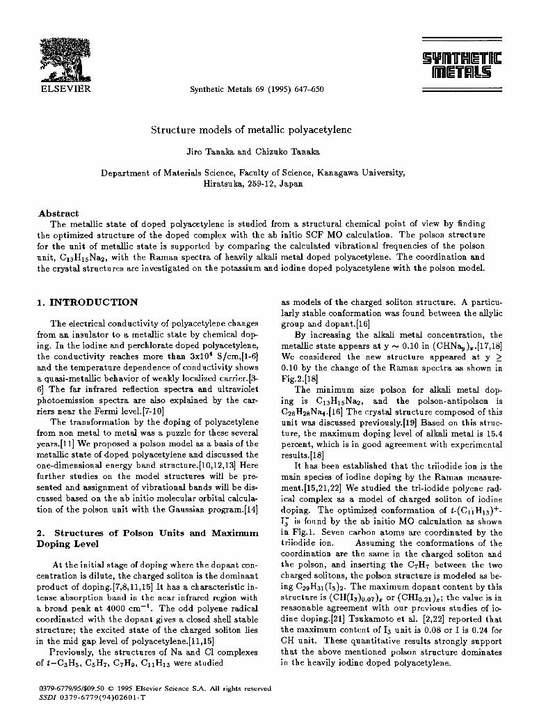
We have discussed previously on the polson- antipolson lattice composed of CssHguN~ and showed a close correlation of the structure to the other al- kali doped polyacetylene.[l9,20] In fact, the crys- tals of sodium doped polyacetylene are not stable for X-ray experiment, accordingly we have calculated the optimized geometry of Cr3Hr5K2 by the basis functions for C(321/21/1*1*), K+(3321/321/1*1*) and H (21/1*).[23,24] The polson-antipolson structure is shown in Figure 3. The calculated positions of K+ ion are shown by small circles and those found by experi- ment are given by black dots. The K - K distance is 8.0 A.
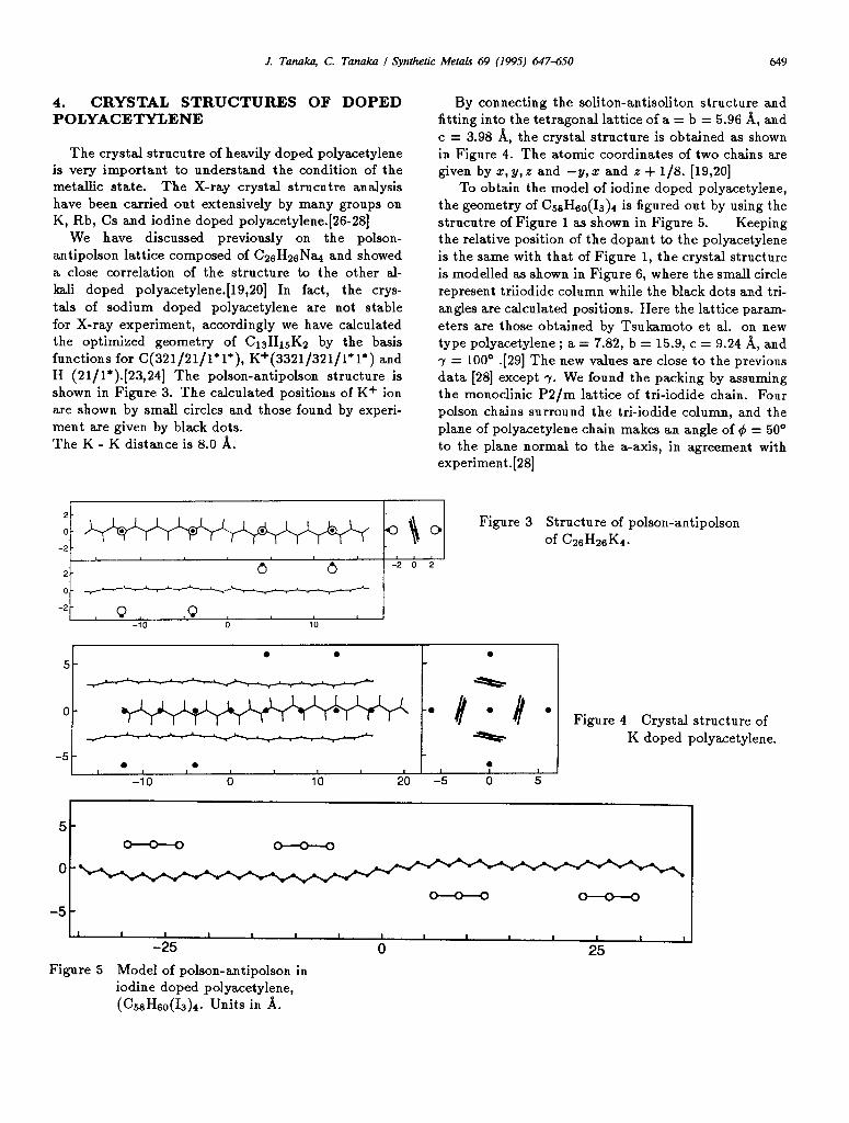
By connecting the soliton-antisoliton structure and fitting into the tetragonal lattice of a = b = 5.96 %I, and c = 3.98 A, the crystal structure is obtained as shown in Figure 4. The atomic coordinates of two chains are given by z, y, z and -y, z and z + l/8. [19,20]
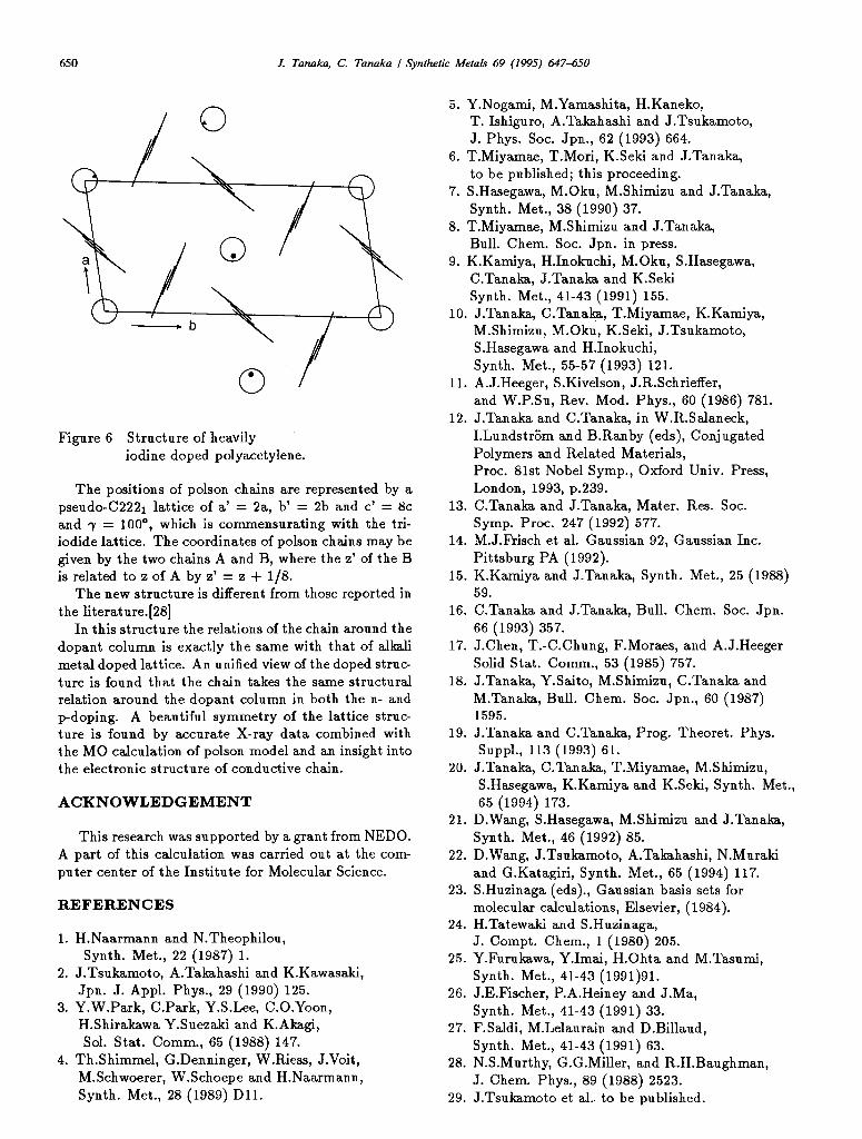
To obtain the model of iodine doped polyacetylene, the geometry of C H (I ) 5s su 3 4 is figured out by using the strucutre of Figure 1 as shown in Figure 5. Keeping the relative position of the dopant to the polyacetylene is the same with that of Figure 1, the crystal structure is modelled as shown in Figure 6, where the small circle represent triiodide column while the black dots and tri- angles are calculated positions. Here the lattice param- eters are those obtained by Tsukamoto et al. on new type polyacetylene ; a = 7.82, b = 15.9, c = 9.24 A, and 7 = 100” .[29] Th e new values are close to the previous data [28] except 7. We found the packing by assuming the monoclinic P2/m lattice of tri-iodide chain. Four polson chains surround the tri-iodide column, and the plane of polyacetylene chain makes an angle of Q = 50’ to the plane normal to the a-axis, in agreement with experiment.[28]
0 Figure 3 Structure of polson-antipolson
of GdbsK4.
6 0 -2 0 2
0 - e.__._ -2- , 0, .Q
-10 0 10
. . I . I 5t t I
Figure 4 Crystal structure of K doped polyacetylene.
5 c 1 I - 0 v 0 I
Figure 5 Model of polson-antipolson in iodine doped polyacetylene, (CssHsu(13)4. Units in A.
650 J. Tanaka, C. Tanaka I Synthetic Metals 69 (1995) 647-650
Figure 6 Structure of heavily iodine doped polyacetylene.
The positions of polson chains are represented by a pseudo-C2221 lattice of a’ = 2a, b’ = 2b and c’ = 8c and 7 = 100°, which is commensurating with the tri- iodide lattice. The coordinates of polson chains may be given by the two chains A and B, where the z’ of the B is related to z of A by z’ = z + l/8.
The new structure is different from those reported in the literature.[28]
In this structure the relations of the chain around the dopant column is exactly the same with that of alkali metal doped lattice. An unified view of the doped struc- ture is found that the chain takes the same structural relation around the dopant column in both the n- and p-doping. A beautiful symmetry of the lattice struc- ture is found by accurate X-ray data combined with the MO calculation of polson model and an insight into the electronic structure of conductive chain.
ACKNOWLEDGEMENT
This research was supported by a grant from NEDO. A part of this calculation was carried out at the com- puter center of the Institute for Molecular Science.
IXEFERJZNCES
1. H.Naarmann and N.Theophilou, Synth. Met., 22 (1987) 1.
2. J.Tsukamoto, A.Takahashi and K.Kawasaki, Jpn. J. Appl. Phys., 29 (1990) 125.
3. Y.W.Park, C.Park, Y.S.Lee, C.O.Yoon, H.Shirakawa Y.Suezaki and K.Akagi, Sol. Stat. Comm., 65 (1988) 147.
4. Th.Shimmel, G.Denninger, WRiess, J.Voit, M.Schwoerer, W.Schoepe and H.Naarmann, Synth. Met., 28 (1989) Dll.
5. Y.Nogami, M.Yamashita, H.Kaneko, T. Ishiguro, A.Takahashi and J.Tsukamoto, J. Phys. Sot. Jpn., 62 (1993) 664.
6. T.Miyamae, T.Mori, K.Seki and J.Tanaka, to be published; this proceeding.
7. S.Hasegawa, M.Oku, M.Shimizu and J.Tanaka, Synth. Met., 38 (1990) 37.
8. T.Miyamae, M.Shimizu and J.Tanaka, Bull. Chem. Sot. Jpn. in press.
9. K.Kamiya, H.Inokuchi, M.Oku, S.Hasegawa, C.Tanaka, J.Tanaka and K.Seki Synth. Met., 41-43 (1991) 155.
10. J.Tanaka, C.Tanaka, T.Miyamae, K.Kamiya, M.Shimizu, M.Oku, K.Seki, J.Tsukamoto, S.Hasegawa and H.Inokuchi, Synth. Met., 55-57 (1993) 121.
11. A. J.Heeger, S.Kivelson, J.R.Schrieffer, and W.P.Su, Rev. Mod. Phys., 60 (1986) 781.
12. J.Tanaka and C.Tanaka, in W.R.Salaneck, I.Lundstrijm and B.Ranby (eds), Conjugated Polymers and Related Materials, Proc. 81st Nobel Symp., Oxford Univ. Press, London, 1993, p.239.
13. C.Tanaka and J.Tanaka, Mater. Res. Sot. Symp. Proc. 247 (1992) 577.
14. M.J.Frisch et al. Gaussian 92, Gaussian Inc. Pittsburg PA (1992).
15. K.Kamiya and J.Tanaka, Synth. Met., 25 (1988) 59.
16. C.Tanaka and J.Tanaka, Bull. Chem. Sot. Jpn. 66 (1993) 357.
17. J.Chen, T.-C.Chung, F.Moraes, and A.J.Heeger Solid Stat. Comm., 53 (1985) 757.
18. J.Tanaka, Y.Saito, M.Shimizu, C.Tanaka and M.Tanaka, Bull. Chem. Sot. Jpn., 60 (1987) 1595.
19. J.Tanaka and C.Tanaka, Prog. Theoret. Phys. Suppl., 113 (1993) 61.
20. J.Tanaka, C.Tanaka, T.Miyamae, M.Shimizu, S.Hasegawa, K.Kamiya and K.Seki, Synth. Met., 65 (1994) 173.
21. D.Wang, S.Hasegawa, M.Shimizu and J.Tanaka, Synth. Met., 46 (1992) 85.
22. D.Wang, J.Tsukamoto, A.Takahashi, N.Muraki and G.Katagiri, Synth. Met., 65 (1994) 117.
23. S.Huzinaga (eds)., Gaussian basis sets for molecular calculations, Elsevier, (1984).
24. H.Tatewaki and S.Huzinaga, J. Compt. Chem., 1 (1980) 205.
25. Y.Furukawa, Y.Imai, H.Ohta and M.Tasumi, Synth. Met., 41-43 (1991)91.
26. J.E.Fischer, P.A.Heiney and J.Ma, Synth. Met., 41-43 (1991) 33.
27. F.Saldi, M.Lelaurain and D.Billaud, Synth. Met., 41-43 (1991) 63.
28. N.S.Murthy, G.G.Miller, and R.H.Baughman, J. Chem. Phys., 89 (1988) 2523.
29. J.Tsukamoto et al.. to be published.