structural vibration for robotic communication...
TRANSCRIPT

Structural Vibration for Robotic Communication and Sensing onOne-Dimensional Structures
Maxwell Hill1, Jerry Mekdara2, Barry Trimmer2 and Robert White1
Abstract— In this paper, structure-borne vibrations in a one-dimensional structure are examined as a means of communica-tion and sensing for networks of robots. The concept is inspiredby the observation that insects may use structural vibrationsto communicate and to detect features of their environment.A 12 x 5 x 6 cm mobile robot capable of traversing anacoustically favorable structure is presented. A technique formeasuring distance between robots and communicating com-mands to robots using vibrations generated on a common one-dimensional substrate are presented, and demonstrated throughpreliminary experimental results. Design considerations for thistype of system are also discussed.
I. INTRODUCTIONCreatures in nature transmit and receive informa-
tion at high speeds using structure-borne vibration. Thismechanocommunication is direct in the sense that the trans-mitted information is generated by another creatures move-ment, and the received signal is a sensory response to thisaction. In fact, 70 % of insect species may use substratevibration of some form to communicate [1].
Fig. 1. Manduca sexta caterpillar on a wooden dowel exhibiting a strikereflex (top) and the resultant transverse vibration at the substrate (bottom).
Many species of caterpillar communicate by producingand responding to sounds and substrate vibrations [2], [3].Although Manduca caterpillars do not live in communities,they do produce trains of clicks (3 s trains, dominant fre-quency around 30 kHz) as part of their defensive behavior[4]. A vibratory response generated by striking behavior isillustrated in Fig. 1.
*This work was supported by the National Science Foundation1Maxwell Hill and Robert White are with the Department of Me-
chanical Engineering, Tufts University, Medford, MA 02155, [email protected] and [email protected]
2Jerry Mekdara and Barry Trimmer are with the De-partment of Biology, Tufts University, Medford, MA02155, USA [email protected] [email protected]
Some species can discriminate substrate vibrations pro-duced by abiotic influences (rain, wind), conspecifics, andpredators [5], [6]. A recent phylogenetic and morphologicalstudy suggested that ritualized vibratory signals (producedby anal scraping) originated from walking behavior [7].One possibility, not yet explored, is that, before vibrationdetection was used for active communication, it evolvedfor evaluating the mechanical properties of the environment.Surface texture, stiffness and slip can all be detected throughoscillations in shear force (vibrations) [8], [9].
A vibration communication and sensing system is pro-posed for mobile robots. This system would have advantagesover RF communication in situations of limited spectrumand signal interference. The scheme is also covert in thatit only allows communication between devices on the samesubstrate; devices close to the system cannot listen if theyare mechanically isolated from the structure.
In addition to communication, vibrations can be used tosense properties of the environment. Interactions of the vi-brations with branch points or terminal points in a structure,resulting in reflections, could allow the robot to generatelocal maps of the structure on which it is traveling.
One dimensional branching structures such as cables,structural trusses, pipes, and tracks, as well as natural struc-tures like trees, are of particular interest for this application.These types of structures are very common in both natureand in human construction, and are important environmentsfor robots tasked with inspection, material transportation,and surveillance tasks. These structures can support variousmodes of vibration including bending, torsional, and longi-tudinal vibrations [10]. Due to the one-dimensional nature ofthe structure, vibrations do not spread geometrically, poten-tially allowing for long range communication and sensing.The dispersive nature of bending waves in the vibratingstructure can be exploited to give additional informationabout the environment that might not be available for non-dispersive waves such as longitudinal pressure waves.
Little prior work has been done on the use of structuralvibrations for communication and sensing in robotics. In oneinstance, surface waves were used successfully for commu-nication between robots on a common plate substrate usingcross-correlation methods [11]. However, due to the two-dimensional substrate, this system lends itself only to close-proximity distributed communication methods because thevibrations die out quickly due to both geometric spreadingand absorption. Localization was also achieved by measuringthe variation of Time of Arrival (TOA) at each leg of a six-legged scorpion robot with similar range limitations [12].

A similar strategy, Time Delay of Arrival (TDOA), wasimplemented for a microphone array mounted on a robot forlocalizing sound [13]. Microphones are also used in recentwork in tactile sensing skins for robots utilizes sensor nodenetworks embedded in a flexible substrate to localize objectsand characterize textures [14].
In another piece of prior work, acoustic reflectometry wasused to remotely map complex tunnel networks, detectingdistances to turns, turn types, and closures [15]. This appli-cation has more similarities to the method proposed here; theone dimensional nature of the acoustic medium allows thesignal to propagate over long distances with losses causedonly by absorption.
In this work, we begin to develop the necessary platformsand techniques to explore sensing and communication withstructural vibrations for robots operating on one-dimensionalsubstrates.
II. ROBOTIC PLATFORM AND ENVIRONMENT
A. Robotic Platform
A robotic platform was developed to traverse a trackenvironment and to sense vibration propagated through therails. A four-wheeled design was chosen, with the two frontwheels driven by small geared motors, as shown in Fig. 2.Like wheels on a train, grooves in the wheels maintainalignment between the wheels and rails. In order to negotiateturns, the robot is split into two symmetric segments; whichare pinned about an axis and give it a single degree offreedom.
The angle, θ, of one segment relative to the other, issensed directly using a potentiometer. A Texas InstrumentsEZ430-RF2500 target board controls the robot via an inte-grated MSP430F2274 microcontroller. This microcontrollerincludes eight 10-bit ADC inputs which can be used formonitoring sensors. Currently, the potentiometer is the onlysensor input. A CC2500 2.4GHz radio is also included onthis board for wireless data-logging. A 7.4V 850mAh lithiumpolymer battery pack allows the robot to operate untethered.
Fig. 2. The placement of components on the robot (left) and an illustrationof the kinematics of the robot (right).
Closed-loop control of the robot was needed for the robotto traverse the track smoothly. A compressive preload in thebeams connecting to the wheels maintains grip between thewheels and the rails. The kinematics of the robot governsa maximum angle at which the preload is insufficient to
provide reliable motion. Therefore, a PID control loop waswrapped around θ. In designing the PID controller, Ziegler-Nichols tuning rules were used as a starting point.
The controller has two states: PID and an open-loopturning mode. Switching between these states is initiatedwhen the robot hits a turn and causes to exceed a threshold.An interrupt then exits the PID loop for a single cycle ofthe turning mode control. For more complex track topologieswith forked junctions, a similar strategy can be implemented.Instead of sensing the turns through angle, the junctionfeatures would be sensed via vibration and the robot willdecide which way to turn and steer itself appropriately.
Piezoelectric bimorph cantilevers (PiezoDrive BA4902)serve as vibration transceivers. These cantilevers are idealfor this application because they can be configured both asan actuator or sensor, have high sensitivity, and kilohertzbandwidth. Similar elements were successfully used to detectvibration in a robot scorpion [13].
Fig. 3. Charge amplifier circuit used to condition piezoelectric cantileversensor output.
To configure the cantilevers as actuators, a voltage am-plifier (PiezoDrive PDu100B) steps up the on-board batteryvoltage up to 100 V to induce significant strain in thecantilevers. The amplifier operates over a nominal bandwidthof 3.2 kHz at 100 V, which is sufficient for preliminaryinvestigation of communication and sensing schemes. Forsensing, a charge amplifier circuit was constructed basedon a transimpedance amplifier (current-to-voltage converter)topology, for measuring deflection of the piezoelectric can-tilevers. A schematic of the charge amplifier is shown inFig. 3.
B. Environment
In order to study vibration as a means of communicationand sensing, an environment with low energy loss throughdamping was needed. Additionally, the structure needed tobe simple enough for a robot to traverse robustly. A trackstructure was decided on with three carbon fiber rails; two ofthe rails are for the robot to attach to and one rail allowingvibration transmission. In order to test the robots mobility,the track was constructed in the shape of a closed loop, withthe ability to add branches later (Fig. 4). The turn segmentswere 3D-printed from Stratsys VeroClear-RGD810 materialand bonded to the straight carbon fiber segments with Loctite

Super Glue. The structure is 60 x 30cm in dimension, withfour constant-radius 90 degree turns.
Fig. 4. Robot navigating track (a), a close-up of the three-rail structure(b), and a section view along the track (c).
III. MODELING
Before extending vibration communication and sensingmethods to a robotic platform, modeling was needed topredict how vibrations propagate through the structure, andfind any limitations. To reduce the problem, a single straightsegment of the structure (Fig. 4) was investigated. In themodel, two piezoelectric cantilevers are included; one can-tilever provides a forcing to the structure and a second (at an-other location) senses structural vibration. These cantileversrepresent the transducers on a pair of robots. A steady-statemodel was created from the loading configuration shown inFig. 5.
Fig. 5. Beam model loading configuration with boundary conditions.
The dynamic Euler-Bernoulli equation for beams was usedas the basis of the model. This model is typically used forslender bending beams with no axial tension or compression[16].
EI∂4u
∂x4+ ρA
∂2u
∂t2= 0 (1)
Here, u(x, t) is the transverse displacement, EI is thebending stiffness, and ρA is the mass per unit length.Arbitrary mechanical termination impedances are prescribedat the boundaries x = 0 and x = L, giving rise to fourboundary conditions,
at x = 0
M |x=0 = EI∂2u
∂x2
∣∣∣∣x=0
= Zθ∂u
∂x
∣∣∣∣x=0
(2)
V |x=0 = EI∂3u
∂x3
∣∣∣∣x=0
= Ztu|x=0 (3)
and at x = L
M |x=L = EI∂2u
∂x2
∣∣∣∣x=L
= Zθ∂u
∂x
∣∣∣∣x=L
(4)
V |x=L = EI∂3u
∂x3
∣∣∣∣x=L
= Ztu|x=L (5)
The cantilevers discussed in section II can be modeledas a simple mass-spring system as depicted in Fig. 6, whereH = meω
2−kejω is the mechanical impedance of the cantilever.
Fig. 6. Piezoelectric cantilever modeled as mass-spring system.
The values of me and ke are determined by calculatingthe first mode of the cantilever,
Ω1 = 0.5969π (6)
ω1 =
√EI
ρA
Ω21
L2(7)
ke =Ewh3
4L3(8)
me =keω21
(9)
The input oscillation of the actuator, described as a har-monic force of magnitude F0 at x = l2 generates a forcebalance condition,
V |x=l1,left + V |x=l1,right = −Hjω u|x=l1 (10)
and a similar condition at the sensor location x = l1
V |x=l2,left + V |x=l2,right= −Hjω u|x=l2 + F0e
jωt (11)
Six more boundary conditions arise by prescribing con-tinuity of displacements, angles, and moments over theboundaries at x = l1 and x = l2,

u|x=l1,left = u|x=l1,right (12)
∂u
∂x
∣∣∣∣x=l1,left
=∂u
∂x
∣∣∣∣x=l1,right
(13)
∂2u
∂x2
∣∣∣∣x=l1,left
=∂2u
∂x2
∣∣∣∣x=l1,right
(14)
u|x=l2,left = u|x=l2,right (15)
∂u
∂x
∣∣∣∣x=l2,left
=∂u
∂x
∣∣∣∣x=l2,right
(16)
∂2u
∂x2
∣∣∣∣x=l2,left
=∂2u
∂x2
∣∣∣∣x=l2,right
(17)
For steady-state response at a single frequency we expectthe solution to (1) to be of the following form, with twotraveling waves (A and B) and two evanescent waves (C andD),
ui(x, t) = Aiej(ωt−kx) +Bie
j(ωt+kx)
+Ciejωtekx +Die
jωte−kx (18)
where the wavenumber comes from the solution of thecharacteristic equation for the governing ODE,
k =√ω
(EI
ρA
)1/4
(19)
It should be noted for bending waves that the wavenumberis proportional to the square root of frequency. This isequivalent to saying the wave speed for this dispersive waveis not constant; it varies inversely as the square root offrequency. This means that waveforms transmitted from oneposition will arrive with a different shape due to frequencydependent phase delays. Hence, typical methods used withRF and acoustic waves will not be optimal for use withdispersive waves such as structural bending.
The equations created by the twelve boundary conditionscan be written in matrix form and solved for the coefficientsthrough matrix inversion. Time is implicit in this steady-statemodel. The solutions arrived at are steady state, harmonicsolutions. For finite structures with little damping, thesesteady state vibrations are quickly established. This is also animportant feature of this type of substrate which differs fromthe typical mental model we may have of vibrations travelingout and away from a source in large spaces or spaces withconsiderable damping. Rather, vibrational energy is trappedin the one dimensional structure and quickly establishes asteady state vibration pattern which must be interpreted assuch for communication and sensing.
Linearity of the governing equation ensures that multiplesolutions at different drive frequencies may be superimposed.Depending on the impedances at the ends of the beam,different behaviors are observed. These behaviors range frompure standing waves to pure traveling waves, depending on
how well the impedance boundary conditions are matched tothe characteristic impedance for the bending wave.
Electromechanical coupling was also considered in thismodel. A coupling constant kt relating the tip velocity ofthe piezoelectric cantilever to input current was derived [17].For the first mode of the cantilever,
kt =−3d31Ebh
4L(20)
where d31 is a piezoelectric constant; E is the modulus;and b, h, L are geometric parameters. The current throughthe cantilever is described as a function of kt, as shown inFig. 3 above. Similarly, the amplitude of the force generatedby the cantilever and exerted onto the beam is expressed asF0 = ktVapp. The voltage amplifier is linear with a knowngain.
Fig. 7. Comparison of experiment and model prediction of sine-sweep ofthe piezoelectric sensor.
The model was validated by measuring the frequencyresponse for physical embodiment of the model. In Fig. 7we see the prediction captures the shape of the measuredfrequency response well. All parameters in the model aretextbook properties and have not been tuned. The 13 dBlower signal level seen in experiment as compared to themodel is under investigation. More importantly, this resultshows that in this frequency range the dynamics of thecantilever dominate those of the beam, which is an importantconsideration for the design of communication and sensingschemes.
IV. COMMUNICATION AND SENSING
One salient quantity to measure in the context of robotnetworks is the distance between robot agents. We take thisproblem as an example of how steady state standing wavesin a dispersive structure might be used to sense position.The method considered for this calculation examines phasechange of an oscillation measured at a distance from theinput. Here, phase refers to discrete regimes; the response iseither in-phase or out-of-phase with the input.
In this scheme, a vibration is induced at a point alonga beam and the response at any point on the beam can bereferenced to this driving vibration to obtain a phase. In a
standing wave regime of a single frequency, the phase togglesbetween zero (in-phase) and 180 degrees (out-of-phase) atwave nodes. If the phase is interpreted as a binary code, fortwo drive frequencies, this gives a 2-bit output with positionresolution determined by the half wavelength of the shortestwave.
Fig. 8. Simulated beam response to three harmonic excitations (1 kHz, 4kHz, and 16 kHz) (top) and the resulting phase interpreted as a three bitdistance code (bottom).
Additional frequency components can be superimposed toincrease spatial resolution. Doing so improves the resolutionof the distance measurement from 2-bit to N-bit
R = λ0/2N (21)
where N is the number of frequency components used andλ0 is the wavelength of the lowest frequency (in Fig. 8 N=3and λ0 = 0.9 m). Each subsequent frequency selected shouldbe four times the previous frequency in order to halve thewavelength, due to the square root nature of the wavenumberin equation (19). This relationship affects the required systembandwidth as
BW = f0(4(N−1) − 1) (22)
where f0 is the lowest frequency component. For this par-ticular example, for a 90 cm long structure, three frequencycomponents result in a spatial resolution of 11cm/bit. It iseasy to imagine a signal with eight frequency components,which would achieve 0.35 cm/bit. The bandwidth growthwith N, described in equation (22), does present a limitationon the number of frequency components. It is noted that f0need not be selected as a fundamental frequency, potentiallyshifting f0 to a more tractable (lower) frequency for imple-mentation in hardware. Nonetheless, bandwidth should beconsidered when selecting a vibration source and samplingrate.
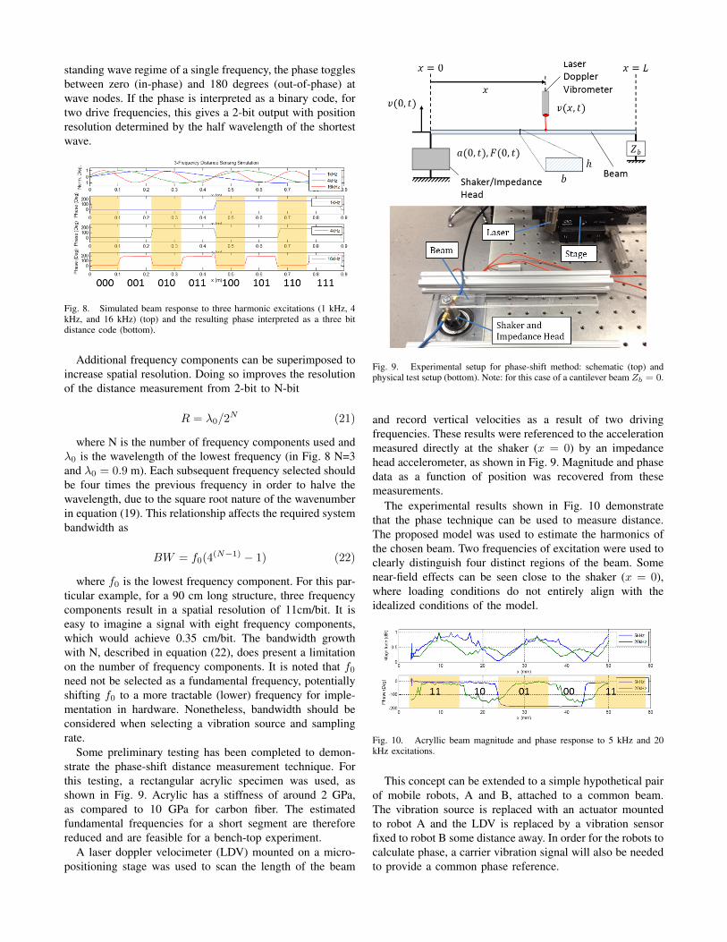
Some preliminary testing has been completed to demon-strate the phase-shift distance measurement technique. Forthis testing, a rectangular acrylic specimen was used, asshown in Fig. 9. Acrylic has a stiffness of around 2 GPa,as compared to 10 GPa for carbon fiber. The estimatedfundamental frequencies for a short segment are thereforereduced and are feasible for a bench-top experiment.
A laser doppler velocimeter (LDV) mounted on a micro-positioning stage was used to scan the length of the beam
Fig. 9. Experimental setup for phase-shift method: schematic (top) andphysical test setup (bottom). Note: for this case of a cantilever beam Zb = 0.
and record vertical velocities as a result of two drivingfrequencies. These results were referenced to the accelerationmeasured directly at the shaker (x = 0) by an impedancehead accelerometer, as shown in Fig. 9. Magnitude and phasedata as a function of position was recovered from thesemeasurements.
The experimental results shown in Fig. 10 demonstratethat the phase technique can be used to measure distance.The proposed model was used to estimate the harmonics ofthe chosen beam. Two frequencies of excitation were used toclearly distinguish four distinct regions of the beam. Somenear-field effects can be seen close to the shaker (x = 0),where loading conditions do not entirely align with theidealized conditions of the model.
Fig. 10. Acryllic beam magnitude and phase response to 5 kHz and 20kHz excitations.
This concept can be extended to a simple hypothetical pairof mobile robots, A and B, attached to a common beam.The vibration source is replaced with an actuator mountedto robot A and the LDV is replaced by a vibration sensorfixed to robot B some distance away. In order for the robots tocalculate phase, a carrier vibration signal will also be neededto provide a common phase reference.

Further, a scheme for transmitting commands over vibra-tion has been demonstrated on this robotic platform. Therobot ’listens’ for a burst (sinusoid at a uniform frequency)generated by a piezoelectric cantilever mounted to the track.Depending on the duration of the detected burst, the robotexecutes a distinct motor command, illustrated experimen-tally in Fig. 11.
Fig. 11. The robot measures a 100 cycle burst and responds by executinga short ( 0.5 sec) drive command (top), while a 600 cycle burst triggers alonger ( 3 sec) drive command. Both bursts are at 200 Hz.
The robot behavior (motor drive signal) is recorded todemonstrates that the robot can distinguish discrete com-mands by looking only at properties of received structuralvibration. While this demonstration shows one-directionalcommunication, it can easily be extended to pairs of robotswith the ability to both actuate and sense vibration, for two-way communication.
V. CONCLUSIONStructural vibrations are used by insects to communicate
and sense information about their environment. This useof vibration may also be useful for mobile robots, partic-ularly if operating on one dimensional branched structuressuch as cables, structural trusses, tracks, piping systems ornatural structures such as trees. The method is particularlyinteresting in one-dimensional structures, since vibrationscan propagate over long distances without the attenuationassociated with geometric spreading that would occur in twoand three dimensional spaces.
In this work we described a mobile robotic platform on atrack that will be used to explore practical methodologies forthe use of structure borne vibration in communication andsensing. We have demonstrated the ability to send simplecommands to a mobile robot using structure borne vibration.An example methodology for distance sensing employingmulti-frequency standing waves in a bending beam wasdemonstrated in a physics-based model and in experiment.
In future work we intend to explore the use of multiplerobots agents on this platform. Additional communicationschemes can be developed, employing FFT techniques todistinguish transmissions from multiple robots transmitting
at distinct carrier frequencies. We also plan to test the lim-itations (range, resolution, and bandwidth) of the proposeddistance-sensing scheme.
ACKNOWLEDGMENT
This research was supported in part by the NationalScience Foundation grants, IOS-1050908 to Barry Trimmer,IGERT-1144591 to Barry Trimmer and David Kaplan, andDBI-1126382 to Robert White.
REFERENCES
[1] R. Matthews, J. Matthews, Insect Behavior. Dordrecht, The Nether-lands: Springer Netherlands, 2010, pp. 291-339.
[2] Yack, J., M. Smith, and P. Weatherhead, Caterpillar talk: acousticallymediated territoriality in larval Lepidoptera. Proceedings of the Na-tional Academy of Sciences, 2001. 98(20): p. 11371-11375.
[3] Yack, J.E., S. Gill, C. Drummond-Main, and T.N. Sherratt, ResidencyDuration and Shelter Quality Influence Vibratory Signalling Displaysin A Territorial Caterpillar. Ethology, 2014. 120(4): p. 354-364.
[4] Bura, V.L., A.K. Hnain, J.N. Hick, and J.E. Yack, Defensive soundproduction in the tobacco hornworm, Manduca sexta (Bombycoidea:Sphingidae). Journal of insect Behavior, 2012. 25(2): p. 114-126.
[5] Guedes, R., S. Matheson, B. Frei, M. Smith, and J. Yack, Vibrationdetection and discrimination in the masked birch caterpillar (Drepanaarcuata). Journal of Comparative Physiology A, 2012. 198(5): p. 325-335.
[6] Castellanos, I. and P. Barbosa, Evaluation of predation risk by acaterpillar using substrate-borne vibrations. Animal Behaviour, 2006.72(2): p. 461-469.
[7] Scott, J.L., A.Y. Kawahara, J.H. Skevington, S.-H. Yen, A. Sami, M.L.Smith, and J.E. Yack, The evolutionary origins of ritualized acousticsignals in caterpillars. Nature communications, 2010. 1: p. 4.
[8] Greenleaf, J.F., M. Fatemi, and M. Insana, Selected methods forimaging elastic properties of biological tissues. Annual Review ofBiomedical Engineering, 2003. 5(1): p. 57-78.
[9] Tiwana, M.I., S.J. Redmond, and N.H. Lovell, A review of tactilesensing technologies with applications in biomedical engineering.Sensors and Actuators A: Physical, 2012. 179(0): p. 17-31.
[10] Johnson, K.O., The roles and functions of cutaneous mechanorecep-tors. Current opinion in Neurobiology, 2001. 11(4): p. 455-461.
[11] Silvola, Ari, Russell, Robin. Australian Robotics and AutomationAssoc; 2005. Robot communication via substrate vibrations.
[12] Wallander, A., Russell, R.A., and Hyyppa, K., ’A robot scorpionusing ground vibrations for navigation’, Proceedings of the AustralianConference on Robotics and Automation, Melbourne, Aug 30- Sept1, 2000, pp. 75-79.
[13] J. Valin, F. Michaud, J. Rouat, D. Letourneau, ”Robust SoundSource Localization Using a Microphone Array on a Mobile Robot.”IEEE/RSJ International Conference on Intelligent Robots and Systems,2004.
[14] D. Hughes, N. Correll, ’A Soft, Amorphous Skin that can Sense andLocalize Textures’, IEEE International Conference on Robotics andAutomation, 2014.
[15] Bowen, David. Development of a portable system for acousticalreconstruction of tunnel and cave geometries. J. Acoust. Soc. Am.129, 2514 (2011).
[16] Inman, D. J. Engineering Vibration. 4th ed. Upper Saddle River, NJ:Pearson/Prentice Hall, 2014. 532-44. Print.
[17] Weinberg, Marc S. ”Working equations for piezoelectric actuators andsensors.” Microelectromechanical Systems, Journal of 8.4 (1999): 529-533.