structural systematics of drug-like molecules: from
TRANSCRIPT

i
Structural systematics of drug-like molecules: from
benzamides to tennimides
by
Pavle Močilac, M. Pharm.
A thesis presented for the degree of Doctor of Philosophy
at
Dublin City University
Ollscoil Chathair Bhaile Atha Cliath
School of Chemical Sciences
May 2012

ii
to my lovely wife Lei who was supporting me through rain and shine,
and my parents Ivan and Barbara whose love, strength and wisdom
sent me to the way I follow

iii
DECLARATION
I hereby certify that this material, which I now submit for the assessment on the
programme of study leading to the award of Ph.D. is entirely my own fork and has not
been taken from the work of others save and to the extent that such work has been cited
and acknowledged within the text of my work
Signed:_______________________ ID No:____________________
Pavle Mocilac
Date: _____________________________

iv
ACKNOWLEDGEMENTS First and foremost I would like to thank to my supervisor, Dr. John F. Gallagher
for his outstanding support, encouragement and patience during this work.
I would also like to express my gratitude to:
Dr. Alan J. Lough at the Department of Chemistry, University of Toronto,
Canada, for obtaining X-ray crystallographic data in period from January 2009 to
January 2010.
Dr. Christine Loscher in the School of Biotechnology, Dublin City University,
for excellently organised T3 programme.
Dr. Neal Lemon and Sharon Whyte for managing T3 programme.
Prof. Kieran Nolan in the School of Chemical Sciences, Dublin City University
for useful advice and help.
Dr. Turlough Downes, in the School of Mathematical Sciences in Dublin City
University on useful help on calculations.
All students that worked with me, Niall Hehir, Islam Ali Osman, Chloe Violin,
Mark Farrell, Marie Bélières, Marion Lefevre and Fabian Pohl for their work and
friendship, as well as to former students Mark Talon and Katie Donnelly for their
contributions.
All technicians and staff of the School of Chemical Sciences especially to John
McLoughlin for his excellent help and advice on NMR, as well as to Damien McGuirk,
Veronica Dobbyn, Ambrose May, Vincent Hooper and Brendan Twamley for their high
professionalism and excellent service.
Staff and professionals at Irish Centre for High-End Computing, Dr. Alin M.
Elena, Eoin Brazil, Rosemarie Lalor and Dr. Jean-Christophe Desplat for their
cooperation and help.
All my colleagues from organic lab, Sarrah Kebbell, Ian G. Beadham, Declan
Daly, Andy Garry, Sharon Murphy, Brian Murphy, Oksana Shvydkiv, Kieran Joyce,
William Butler, Monika Grubisz, Thomas Hayes, Marcello Iacono, Shelly Long,
Rohitkumar Gore, Fadi Hatoum and Mukund Ghavre for their help, support and
friendship.

v
ABSTRACT
A structural systematic study was undertaken on benzamides, carbamates and
substituted benzamide derivatives as 3×3 isomer grids comprising N-
(pyridyl)benzamide (Fxx and Mxx) (x = para-/meta-/ortho-) and N-
(phenyl)pyridinecarboxamide (NxxF and NxxM) grids. These were synthesised and
characterised, with their crystal structures determined by single crystal X-ray
diffraction. Five series of CxxR (R = CH3, OCH3, F, Cl, Br) carbamate isomer grids
have been synthesised and characterised, with some pertinent structures determined by
X-ray diffraction. Ab initio modelling, conformational analysis and comparisons of
experimental solid state with optimised molecular geometries have facilitated an
examination of the relationships between conformations and inter/intramolecular
interactions, rationalisation of differences between the solid state and calculated
structures, as well as the presence of molecular disorder and polymorphism.
New classes of macrocycles have been developed including tetramers and
trimers, based on our earlier research on benzamides and carbamates. These systems
include various para-substituted derivatives (F, Cl, Br, CH3 CO2CH3) and have been
fully characterized by 1H,
13C,
19F NMR and IR spectroscopy, while their crystal and
molecular structures have been determined by single crystal X-ray diffraction.
The development of tennimides and trezimides as new macrocycles based on an
imide backbone, presents an important entry point into a potentially fruitful area.
Furthermore, discovery of trezimides is especially important since no analogous
macrocycle has been reported. Synthesis of tennimides and trezimides has been
accomplished using a one-step synthetic strategy over a range of derivatives and
presents a basis for synthesis of analogous macrocycles. Tennimides and trezimides
proved to be rigid and stable compounds. The determining factors in the cyclisation are
(i) the presence of the imide ortho-pyridine/pyrimidine rings and (ii) the inherent ability
of the imide group to twist by 80-120°, as measured by the 'CO···CO' torsion angle,
providing a 'hinge' for ring closure or helical assembly. The trezimides can adopt two
distinct conformations in the solid state, (though one is preferred), whereas the
tennimides adopt discrete conformational states as oc, cc and oo that highlight subtle
macrocyclic geometric changes on cavity opening (o) and closing (c) (though these
interconvert in solution).

vi
ABBREVIATIONS
ATR-IR Attenuated Total Reflectance Infrared spectroscopy
B3LYP Becke, Three-parameter, Lee-Yang-Parr
CBS-QB3 Complete Basis Set-Quadratic Becke3
CCD Charge-Coupled Device
COSY Correlation Spectroscopy
CSD Cambridge Structural Database
DEPT Distortionless Enhancement by Polarization Transfer
DEPTQ Distortionless Enhancement by Polarization Transfer - Quaternery
atoms
DFT Density Functional Theory
ESI Electronic Supplementary Information file
HMBC Heteronuclear multiple-bond correlation spectroscopy
HQSC Heteronuclear single-quantum correlation spectroscopy
IR Infrared spectroscopy
Kv channels Voltage Gated Potassium Channels
m.p. Melting Point
MALDI-TOF Matrix-Assisted Laser Desorption/Ionization - Time-Of-Flight
MS Mass spectroscopy
NMR Nuclear Magnetic Resonance
NOESY Nuclear Overhauser effect Spectroscopy
PCM Polarizable Continuum Model
PES Potential Energy Surface
RT Room Temperature
SAR Structure Activity Relationship
SMD Solvation Model Density
SXRD Single Crystal X-Ray Diffraction
TLC Thin layer chromatography
XRD X-Ray Diffraction

vii
Reagents and solvents:
2-AP 2-aminopyridine
26-APM 2-aminopyrimidine
3,4-DAP 3,4-diaminopyridine
3-AP 3-aminopyridine
4-AP 4-aminopyridine
AP Aminopyridine
CDCl3 Deuterated chloroform
CH2Cl2 Dichloromethane
CH3CN Acetonitrile
CH3COCH3 Acetone
CHCl3 Chloroform
Cl3FC Trichlorofluoromethane
DBU 1,8-Diazabicycloundec-7-ene
DMAP Dimethylaminopyridine
DMSO Dimethyl sulfoxide
DMSO-d6 Deuterated dimethyl sulfoxide
DPPA Diphenylphosphoryl azide
Et2O Diethyl ether
Et3N Triethylamine
EtOH Ethanol
HCl Hydrochloric acid
H2SO4 Sulphuric acid
IPA Iso-propyl alcohol
KHCO3` Potassium Hydrogen Carbonate
MeOH Methanol
MgSO4 Magnesium Sulphate
N2 Nitrogen gas
Na2CO3 Sodium Carbonate
NaCl Sodium Chloride
NaOH Sodium Hydroxide
NH4Cl Ammonium Chloride
SOCl2 Thionyl chloride
THF Tetrahydrofuran
TTP Triphenyl phosphite

viii
TABLE OF CONTENTS Title page i
Dedication ii
Declaration iii
Acknowledgements iv
Abstract v
Abbreviations vi
INTRODUCTION 1
1. Basic concepts 2
1.1. Structural systematics, crystallography and computational 2
modelling
1.2. Conformational analysis 3
1.3. Isomer grids 6
2. Objectives 9
2.1. Benzamides 10
2.2. Pyridinecarboxamides 11
2.3. Carbamates 12
3. Pharmacological role of the selected compounds 13
3.1. Potassium channels 13
3.1.1. Structure and assembly of Kv channels 14
3.1.2. Physiology of Kv channels 16
3.2. Potassium channel modulators 16
3.2.1. The Kv blockers 16
3.2.2. The Kv activators 24
4. Summary 30
CHAPTER I: BENZAMIDES AND PYRIDINECARBOXAMIDES 32
1. Benzamides 33
1.1. Mxx isomer grid 33
1.1.1. General description of synthesis 33
1.1.2. General materials and equipment 35
1.1.3. X-ray crystallography methods 35

ix
1.1.4. Computational methods 36
1.1.5. Molecular and crystal structure data 37
1.1.6. Ab initio calculations 47
1.1.7. Comparisons of the solid state and modelling data 52
1.2. Fxx isomer grid 54
1.2.1. General description of synthesis 54
1.2.2. X-ray crystallography methods 55
1.2.3. Computational methods 56
1.2.4. Comment on synthesis and general characteristics 57
1.2.5. Comment on spectroscopic data 57
1.2.6. Crystallographic data and analysis 58
1.2.7. Ab initio calculations 67
1.2.8. Comparisons of the solid state and modelling data 75
2. Pyridinecarboxamides 77
2.1. NxxF isomer grid 77
2.1.1. General description of synthesis 77
2.1.2. Comment on spectroscopic data 79
2.1.3. X-ray crystallography methods 80
2.1.4. Computational methods 80
2.1.5. Molecular and crystal structure data 81
2.1.6. Comments on molecular volumes and melting points 93
2.1.7. Ab initio calculations 94
2.1.8. Comparisons of the solid state and modelling data 99
2.2. NxxM isomer grid 102
2.2.1. General description of synthesis 102
2.2.2. X ray crystallography methods 104
2.2.3. Computational methods 105
2.2.4. Comment on spectroscopic data 105
2.2.5. Crystallographic data and analysis 106
2.2.6. Ab initio calculations 118
2.2.7. Comparisons of the solid state and modelling data 124
CHAPTER II: CARBAMATES 127
1. General description of carbamate syntheses 128

x
1.1. Method 1. Condensation of AP’s with phenyl chloroformates 129
1.2. Method 2. Condensation of 2-AP with phenyl 130
chloroformates in solventless conditions
1.3. Method 3. Curtius rearrangement reaction, variant A 131
1.4. Method 4. Curtius rearrangement reaction, variant B 132
2. Comment on synthesis and general characteristics 133
3. Comment on spectroscopic data 134
4. X-ray crystallographic methods 135
5. Computational methods 135
6. CxxM isomer grid 137
6.1. Molecular and crystal structure data 137
6.1.1. CpxM isomer series 138
6.1.2. CmxM isomer series 141
6.1.3. CoxM isomer series 143
6.2. Ab initio calculations and modelling data 145
6.2.1. Structure optimisation 145
6.2.2. Conformational analysis 146
6.3. Comparisons of the solid state and modelling data 149
7. CxxOMe isomer grid 150
7.1. Molecular and crystal structure data 150
7.1.1. CpxOMe isomer series 151
7.1.2. CmxOMe isomer series 154
7.1.3. CoxOMe isomer series 157
7.2. Ab initio calculations and modelling data 160
7.2.1. Structure optimisation 160
7.2.2. Conformational analysis 162
7.3. Comparisons of the solid state and modelling data 166
8. CxxX compounds 167
8.1. Molecular and crystal structure data 167
8.1.1. CxxF isomer grid 168
8.1.2. CxxCl isomer grid 172
8.1.3. CxxBr isomer grid 175
8.2. Ab initio calculations and modelling data 178
8.2.1. Structure optimisation 178
8.2.2. Conformational analysis 180
xi
8.3. Comparisons of the solid state and modelling data 185
CHAPTER III: TENNIMIDES AND TREZIMIDES 187
1. Introduction 188
1.1. Idea 188
1.2. Historical background and development timeline 189
1.3. Polymer formation 197
1.4. The labelling system and nomenclature 198
1.5. Materials, equipment and spectroscopic methods 199
1.6. X-ray crystallographic methods 199
1.7. Computational methods 199
2. Detailed descriptions of the synthetic procedures 200
2.1. Synthesis of N1,N
3-di(pyridin-2-yl)isophthalamide (H-DIP) 200
2.2. Method 1: The “2+2” synthesis of the IO4 tennimide 200
2.3. Method 2: Standardised, “4+4” synthesis of tennimides and 200
trezimides
3. General comments on spectroscopic data 201
4. IO3 and IO4 macrocycles 202
4.1. Synthesis and purification 202
4.2. General and spectroscopic data 202
4.3. Crystallographic data and discussion 204
5. 26IO3 and 26IO4 macrocycles 208
5.1. Synthesis and purification 208
5.2. General and spectroscopic data 208
5.3. Crystallographic data and discussion 209
5.4. Ab initio geometry optimisation, energies and 213
conformational analysis
6. FIO3 and FIO4 macrocycles 215
6.1. Synthesis and purification 215
6.2. General and spectroscopic data 216
6.3. Crystallographic data and discussion 216
7. ClIO3 and ClIO4 macrocycles 219
7.1. Synthesis and purification 219
7.2. General and spectroscopic data 219

xii
7.3. Crystallographic data and discussion 220
8. BrIO3 and BrIO4 macrocycles 223
8.1. Synthesis and purification 223
8.2. General and spectroscopic data 223
8.3. Crystallographic data and discussion 224
9. 26BrIO3 and 26BrIO4 macrocycles 227
9.1. Synthesis and purification 227
9.2. General and spectroscopic data 228
9.3. Crystallographic data and discussion 228
10. MIO4 macrocycle 231
10.1. Synthesis and purification 231
10.2. General and spectroscopic data 232
10.3. Crystallographic data and discussion 232
11. EsIO3 and EsIO4 macrocycles 234
11.1. Synthesis and purification 234
11.2. General and spectroscopic data 234
11.3. Crystallographic data and discussion 235
DISCUSSION AND CONCLUSIONS 239
1. Benzamides and pyridinecarboxamides 240
2. Carbamates 244
3. Tennimides and trezimide 248
4. Conclusions 251
REFERENCES 254
Appendix I: NMR and IR spectral data
Appendix II: Publications
Electronic supplementary information files (ESI) are provided comprising spectral,
crystallographic and modelling information:
ESI I.pdf – benzamides and pyridinecarboxamides
ESI II.pdf – carbamates
ESI III.pdf – tennimides and trezimides

1
INTRODUCTION
2
1. Basic concepts
1.1. Structural systematics, crystallography and computational modelling
Structural systematics1,2 presents a systematic approach in structural science by
the comprehensive multidisciplinary survey of structurally related compounds. This
term is usually related to methods in solid-state chemistry with the central role of
crystallography, however, investigations of structurally related compounds are
important in other fields of chemistry where the solid state is not central, such as
medicinal chemistry and drug design. The main concept of structural systematics is
comparison of chemical structure data, usually derived from single crystal or powder X-
ray diffraction, with physical properties of structurally similar compounds (salts,
complexes and small organic molecules).
The concept of structural systematics originates in inorganic, coordination and
organometallic chemistry1 and later was extended to areas where more flexible
molecules were in focus, such as drug-like small organic molecules. X-ray diffraction
(XRD) has a key role in structural systematics, as the most powerful experimental
structural method that enables scientists to "see" atoms and molecules, from simple
arrays of ions to large, complex biomolecules. Advancement of crystallographic
methods, computational power (including software for structure solving)3 makes XRD a
routine analytical method of choice. Very often XRD analyses are done just for the sake
of unambiguous identification. XRD is an experimental method that provides real,
averaged information on the structure of crystallised compounds and/or co-crystals.
Structural systematics is a step beyond simple XRD analyses. It implies usage of
structural data derived from many different but similar structures to compare amongst
themselves or with known physical properties, in order to test hypotheses and
eventually expand knowledge in different areas of chemical sciences.
Advances in quantum and computational chemistry,4 modelling methods (ab
initio5, semi-empirical6 and molecular mechanics methods)7 together with increasing
available computational power has brought in new, virtual methods of structural
science, where a molecule is commonly viewed as an isolated entity in gas phase
(vacuum) or as solvated if one of the solvation methods is introduced. A common name
for this area is molecular modelling and is seen as part of theoretical and computational
chemistry. Molecular modelling is usually a corner stone for physico-organic chemistry,
atmospheric chemistry as well as for chemistry of the liquid phase. However, the most

3
important application of molecular modelling is in medicinal chemistry, drug design and
drug development, as 'big pharma' heavily invests in molecular modelling in order to
develop cheaper and structure based ways of drug design.
Structural systematics relies on merging several areas of structural research
(including both crystallography and molecular modelling) and the ability to collate,
integrate and correlate physico-chemical data to provide an insight into physical or
chemical properties within, or between, molecular organic groups.8-11 Such studies and
the comprehensive analyses of large groups of small organic molecules have undergone
enormous advances in the past decade with the advent of information technologies and
instrumentation.8,9,12 Studies combining high throughput syntheses, structural chemistry
and ab initio calculations provide chemical and structural information together with
affording an insight into many physico-chemical properties and trends within molecular
organic series.8,13-16 Advances in synthetic chemistry has allowed for the systematic
synthesis of chemical analogues using reactions amenable to combinatorial chemistry
and high through-put synthesis.17 In tandem, developments in crystallographic and
computational (modelling) fields have facilitated a surge in data generation and
structural analyses for publication and/or archiving8 and based on many classes of
organic molecules.13-16 Structural systematic approaches have utilised polymorphs,9,12
solvates, salts,18 isomers13,16 and homologous series,19,20 with combinations thereof, to
identify patterns of similarities or differences that can aid in the understanding of
chemical and structural properties.8,9,12-16
Comprehensive chemical and computational analyses of small ‘drug-like’
molecules together with structural systematic approaches allow us to utilise an
increasing data stream from both crystallography and computational resources.8,9,13,21
Integration can yield essential information for analysing trends and provide an insight
into similar/different physical or chemical properties within or between molecular
organic series.8,9,13,14,16
1.2. Conformational analysis
One of the important tools in structural systematics is conformational analysis.22
It is an assessment of the relative energies (or thermodynamic stabilities), reactivities,
and physical properties of alternative conformations of a molecular entity, usually by
the application of different modelling methods. Conformation can be defined as a

4
spatial arrangement of the atoms affording distinction between stereoisomers which can
be interconverted by rotations about formally single bonds.23
Conformational isomers or conformers (specifically as rotamers) differ by
rotation about only one single bond. Hence, interconversion of conformers does not
involve breaking or reforming of chemical bonds. The rotational barrier, or barrier to
rotation, is the activation energy required to interconvert rotamers. Rotation of a single
bond in a molecular entity changes the total energy of a molecular system; one or more
particular positions are stable (minimum). The most stable position is called the global
minimum (GM), while others are local minima (LM) or meta-stable positions. An
unstable position where a first derivation equals zero is called a transition state (TS).
Rotation of a single bond that links an individual atom (e.g. H, Cl, F, etc.) or a
linear moiety (e.g. CN group) to a molecular entity will not change the geometry or
energy of a molecular system and therefore, will be neglected in conformational
analyses. Only rotable single bonds whose rotation changes the energy of a system can
be considered. Those are usually bonds linking bulky and/or asymmetric groups and
moieties, as well as rings. Each single bond whose rotation brings a change of energy
presents one degree of conformational freedom (conformational coordinate). A
molecular entity can have one or more degrees of conformational freedom
(conformational coordinates).
In a crystalline solid state, molecular entities are constrained in the crystal
structure by intermolecular interactions, typically in one particular conformation. A
solid state conformation usually presents the most stable one (global minimum, GM0)22
however, in many cases meta-stable or unstable conformations can be adopted due to
the energy compensation by strong and favourable intermolecular interactions.24
Sometimes different conformations can be found in different polymorphs of the same
molecular entity.
In the liquid (solution, melt) phase or in the gas phase, free rotation is enabled,
and therefore, different conformations are possible. A solution or melt is, in fact, a
complex equilibrium of different conformers of the same molecular entity with the
major prevalence of one, the most stable conformer. Prevalence of a particular
conformation depends on the conformational energy difference between conformers as
well as temperature and is driven by the Boltzmann distribution:
∑ =
−
−
=total k
rel
N
k
RTE
RTE
total
i
e
e
N
N
1
/
/
(Eq. 1)

5
The left hand side is the equilibrium ratio of conformer i to the total number of
conformers. Erel is the relative energy of the i-th conformer from the minimum energy
conformer. R is the molar ideal gas constant equal to 8.31 J/mol.K) and T is the
temperature in Kelvin (K). The denominator of the right side is the partition function.
For a molecular system that can adopt two conformations equation 1 can be rearranged
into:
RTEreleP /1
100−+
= (Eq. 2)
P represents the percentage of the lower energy conformer (Fig. 1). Energy
differences between the conformational states are related thermodynamically to their
populations, with a ratio of 1:10 for a free energy difference of ≈ 5.7 kJ.mol-1 at room
temperature. Consequently, conformations with relative free energies larger then 8.4
kJ.mol-1 are populated to a very minor extent (Fig. 1). Conformational analysis can be
accomplished by experimental or theoretical methods. Experimental methods imply
spectroscopic techniques such as dynamic NMR (D-NMR) or IR.
50
60
70
80
90
100
0 1 2 3 4 5 6 7 8 9 10 11 12 13 14 15
Conformational energy difference (kJ.mol-1)
% o
f lo
wer
en
ergy
con
form
er
-80°C
-20°C
0°C
20°C
40°C
60°C
80°C
100°C
200°C
300°C
Fig. 1: Boltzmann distribution as the percentage of the lower energy conformation in a two
conformation equilibrating system as a function of conformational energy difference (x-axis,
kJ.mol-1) at various temperatures (°C, colour).
Theoretical methods that are routinely used, however, differ by the approach and
level of theory (Monte Carlo methods, molecular dynamics, molecular mechanics, semi-
empirical methods, ab initio methods).4-7 Monte Carlo methods and molecular

6
mechanics are less accurate but they take into account the molecule as a whole.
Alternatively, computationally costly ab initio methods are robust and more accurate.
Since computation of all possible conformational space can be very demanding, a
specific, simplified approach can be applied in order to investigate each separate
(isolated) but critical conformational coordinate that is not constrained due to
delocalisation and is likely to be rotated under normal circumstances.4-7
In a particular molecular entity some conformational coordinates may be
considered as generally constrained. One example is the amide bond (NH-C=O). Due to
the delocalisation of electrons (partial double bond) the amide group is relatively planar,
while rotation of the C-N bond at ambient temperature is less likely. Therefore,
constrained conformational coordinates, such as amide C-N bonds, are excluded from
conformational analyses.
Selected critical conformational coordinates are subjected to a method known as
the “conformational scan” in which the conformational coordinate (dihedral angle) is
rotated by a certain increment, and at each step the total energy is calculated. When the
calculated energy is plotted against the corresponding angle the result is a potential
energy surface (PES) diagram. The described method is approximate since it takes into
account only the separated coordinates, and will not give total conformational space. On
the other hand if the method used for energy calculation is accurate enough (ab initio,
DFT) and includes partial optimisation (coordinate relaxation) that allows the entire
molecule to adopt a new conformation, the resulting PES diagram can be considered as
a very accurate model of conformational behaviour in one dimension. Theoretical
conformational analyses are usually accomplished using available quantum chemistry
software packages as Gaussian.25
Crystallisation is a complex process involving thermodynamic as well as kinetic
and many other factors. Such studies with conformational analysis can provide valuable
information on relative energies of different molecular conformations to aid in an
indepth understanding of factors that promote the aggregation and isolation of distinct
and favoured conformations in the solid state.
1.3. Isomer grids
The concept originates from combinatorial chemistry methods where isomers
and moieties are combined into more complex compound libraries in order to yield
numerous compounds that share similar structural motifs, as well as pharmacological

7
activities.26 In medicinal chemistry and drug design the purpose is to cover structural
space in order to increase the probability of a positive outcome (“hit”). In structural
systematics exploring isomer grids is a useful concept to examine the influence of
position variation on structure, aggregation or physico-chemical properties such as
morphology, melting point, reactivity, solubility, stability, crystallinity, optical and
mechanical.
Isomer grids are specific sets of isomers where two or more identical (or
different) substituents (or heteroatoms) exchange their places in a systematic and
combinatorial manner. Isomer grids are based on a fixed scaffold, usually a simple ring
system (6-, 5- or 4-membered aromatic or cycloalkane/ene ring), or complex systems
like tropane, steroid, morphinan, porphyrin and calixarene. A good example of a simple
scaffold is a six-membered aromatic ring. Systematic exchange of the place of the
substituent(s) or heteroatom(s) will give an isomer grid. Two homo- or hetero-
substituents or heteroatoms, (X-A, Y-B; X, Y = any moiety different from H; A, B = N,
O, S) can be arranged to give three different isomers (para, meta, ortho, Scheme 1).
Addition of one more Y-B substituent can yield six possible isomers (Scheme 2). If
there are three different substituents the number of possible isomers increases to ten
(Scheme 3).
B
A
X
Y
B
A
X
YB
A
X
Y
Scheme 1: Possible combinations with two different substituents (para, meta, ortho)
The examples represent simple, one-dimensional isomers grids. If a molecular
scaffold contains two rings connected by a linker it can be used to build a two
dimensional isomer grid. A linker can be symmetric (e.g. simple bond, hydrocarbon
chain, methylene, amino, ether, thio, diazo, ureido, guanido, keto, sulpho, etc.) or
asymmetric (amide, carbamate, ester, sulfonamide, etc.).
Two rings can be labelled X and Y according to the substituent/heteroatom
(Scheme 4). For this particular example the number of possible isomers is 9, since the
combination of two rings with one substituent changing positions gives a 3×3 matrix i.e.
isomer grid (Table 1). Similarly, a two ring scaffold with two identical substituents at

8
each ring gives a 6×6 isomer grid with 36 possible isomers (Table 2), while if
substituents were dissimilar the number of isomers is 100 (10×10 isomer grid).
B B
A
Y
X
Y
B
B
A
X
Y
Y
B B
AY Y
X
B
B
A
Y
Y
X
B
B
A
X
Y
YB
B
A
Y
Y
X
12
345
61
2
34 5
61
2
345
61
2
345
612
345
6 12
345
6
Scheme 2: Possible combinations (6) with three substituents (two being identical): “23”, “24”,
“35”, “26”, “34”, “25”
B C
A
Y
X
Z
C
B
A
X
Y
Z
B
C
A
X
Y
C B
AZ Y
X
B
C
A
Y
ZC
B
A
Z
Y
XX
Z
B
C
A
X
Y
Z
C
B
A
X
Y
Z
C
B
A
Z
Y
X
B
C
A
Y
Z
X
12
345
6
12
345
6
12
345
6
12
345
6
12
345
61
2
345
6
12
345
6
12
345
6
12
345
61
2
345
6
Scheme 3: Possible combinations (10) with three substituents (all different): 2Y3Z, 2Z3Y, 2Y4Z, 2Z4Y, 2Z5Y, 2Y5Z, 2Z6Y, 3Y4Z, 3Z4Y, 3Z5Y
Table 1: A two dimensional (3×3) isomer grid with each ring (X or Y) having one
substituent/heteroatom (X/A or Y/B). A designated letter p, m or o indicates positions of the
substituent on each isomer.
Y X
para meta ortho
para XppY XpmY XpoY
meta XmpY XmmY XmoY
ortho XopY XomY XooY
If three rings are connected with a trivalent linker then it is a tridimensional
isomer grids with 27 (3×3×3), 216 (6×6×6) or 1000 (10×10×10) possible isomers.
Certainly, a complex system can be conceived with n rings, giving a n-dimensional
isomer grid. Therefore, an isomer grid is a matrix of all possible combinations of one

9
dimensional isomers based on an n-dimensional molecular scaffold. Synthesis of isomer
grids has been useful in medicinal and combinatorial chemistry, however, their role in
structural systematics and solid-state chemistry is yet to be established.
A
X
B
Y
YlinkerX
Scheme 4: A scaffold with two rings and a linker is the basis for a two dimensional isomer grid
Table 2: A two dimensional (6×6) isomer grid with each ring (X or Y) having two identical
substituent/heteroatoms (X/A or Y/B). A designated number indicates the positions of the
substituent on each isomer.
Y X
2,3- 2,4- 2,5- 2,6- 3,4- 3,5-
2,3- X23-23Y X23-24Y X23-25Y X23-26Y X23-34Y X23-35Y
2,4- X24-23Y X24-24Y X24-25Y X24-26Y X24-34Y X24-35Y
2,5- X25-23Y X25-24Y X25-25Y X25-26Y X25-34Y X25-35Y
2,6- X26-23Y X26-24Y X26-25Y X26-26Y X26-34Y X26-35Y
3,4- X34-23Y X34-24Y X34-25Y X34-26Y X34-34Y X34-35Y
3,5- X35-23Y X35-24Y X35-25Y X35-26Y X35-34Y X35-35Y
2. Objectives
Our research is directed towards structural systematics of isomer grids
integrating crystal structure analyses with computational (ab initio) modelling methods
to explore the influence of positions of different functional groups e.g.
F/Cl/Br/I/Me/OMe and/or heteroatoms (N) in two dimensional isomer grids based on
semi-rigid drug-like scaffold on inter- and intramolecular interactions, conformations,
physicochemical properties and solid-state packing. Comparisons involve analysis of
the (a) spectroscopic data (b) crystal structures, (c) computational calculations
(geometry optimisation in the gas phase and solvated forms CH2Cl2 and H2O),
molecular energies and ∆Gsolv and (d) conformational analyses of the optimised
structures.
The questions to be addressed involve correlations between the various
permutations of the group site with molecular conformation, solid-state aggregation and
physicochemical properties. The formation of inter/intramolecular hydrogen bonds in
10
the solid state and their influences on molecular conformations are analysed and
collated with conformational and structural differences between theory and experiment.
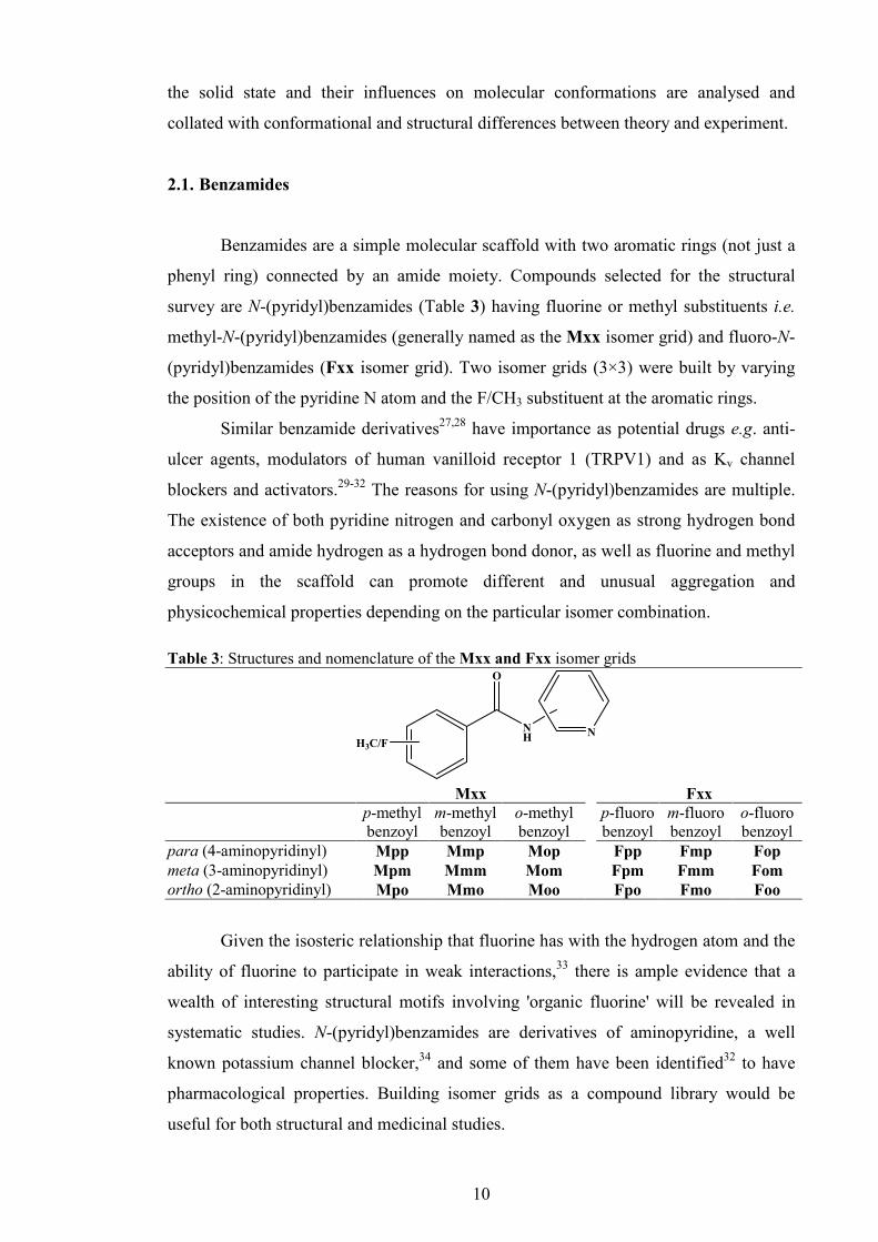
2.1. Benzamides
Benzamides are a simple molecular scaffold with two aromatic rings (not just a
phenyl ring) connected by an amide moiety. Compounds selected for the structural
survey are N-(pyridyl)benzamides (Table 3) having fluorine or methyl substituents i.e.
methyl-N-(pyridyl)benzamides (generally named as the Mxx isomer grid) and fluoro-N-
(pyridyl)benzamides (Fxx isomer grid). Two isomer grids (3×3) were built by varying
the position of the pyridine N atom and the F/CH3 substituent at the aromatic rings.
Similar benzamide derivatives27,28 have importance as potential drugs e.g. anti-
ulcer agents, modulators of human vanilloid receptor 1 (TRPV1) and as Kv channel
blockers and activators.29-32 The reasons for using N-(pyridyl)benzamides are multiple.
The existence of both pyridine nitrogen and carbonyl oxygen as strong hydrogen bond
acceptors and amide hydrogen as a hydrogen bond donor, as well as fluorine and methyl
groups in the scaffold can promote different and unusual aggregation and
physicochemical properties depending on the particular isomer combination.
Table 3: Structures and nomenclature of the Mxx and Fxx isomer grids
NH
O
H3C/FN
Mxx Fxx p-methyl
benzoyl m-methyl benzoyl
o-methyl benzoyl
p-fluoro benzoyl
m-fluoro benzoyl
o-fluoro benzoyl
para (4-aminopyridinyl) Mpp Mmp Mop Fpp Fmp Fop meta (3-aminopyridinyl) Mpm Mmm Mom Fpm Fmm Fom ortho (2-aminopyridinyl) Mpo Mmo Moo Fpo Fmo Foo
Given the isosteric relationship that fluorine has with the hydrogen atom and the
ability of fluorine to participate in weak interactions,33 there is ample evidence that a
wealth of interesting structural motifs involving 'organic fluorine' will be revealed in
systematic studies. N-(pyridyl)benzamides are derivatives of aminopyridine, a well
known potassium channel blocker,34 and some of them have been identified32 to have
pharmacological properties. Building isomer grids as a compound library would be
useful for both structural and medicinal studies.

11
2.2. Pyridinecarboxamides
Pyridinecarboxamides are almost identical and isomeric to N-
(pyridyl)benzamides, however, with the amide linkage being swopped between the rings
(Scheme 5) As in the previous group the fluoro and methyl groups were used as
substituents, giving N-(fluorophenyl)pyridinecarboxamides (NxxF isomer grid) and N-
(tolyl)pyridinecarboxamides (NxxM isomer grid). All four isomer grids are in
relationships regarding the substitent/amide linker variation (Scheme 5).
In contrast to benzamides, pyridinecarboxamides are not direct derivatives of 4-
AP, but rather the reverse or indirect pseudo-derivatives. A literature review reveals
NppF has been used as an intermediate in the synthesis of 4-pyridinium cationic-dimer
antimalarials.35 The NmxF triad has been studied in an unusual synthesis of
nicotinamides36 and recently NmoF has been cited as a promising candidate for lead
design as a selective inhibitor of LmSir2, a sirtuin protein from Leishmania, and
therefore, a potential new drug and/or scaffold for leishmaniasis drug design.37
Table 4: Structures and nomenclature of the NxxF and NxxM isomer grids
NH
O
N
F/CH3
NxxF NxxM p-fluoro
phenyl m-fluoro phenyl
o-fluoro phenyl
p-tolyl m-tolyl o-tolyl
para (4-pyridinoyl) NppF NpmF NpoF NppM NpmM NpoM meta (3-pyridinoyl) NmpF NmmF NmoF NmpM NmmM NmoM ortho (2-pyridinoyl) NopF NomF NooF NopM NomM NooM
In the NoxF series, NopF has been used as a deprotonated ligand in a CoIII complex38
(its crystal structures has been published previously)39 and NomF as an intermediate in
the synthesis of thioamide analogues; NooF has been employed as a ligand in a
ruthenium complex developed as a potential cytotoxic agent.40 The NppM isomer has
been examined as a ligand in metal complexes and complex based polymers with
Cu,41,42 whereas NoxM ligands have been widely studied in metal complexes e.g. Fe,43
Ni,43 Co,43,44 Ru,45,46 Ir,47 Au,48 Mn49,50 and Pt51 with potential and defined catalytic or
electrochemical properties.

12
N
O
NH
CH3
O
NH
N
H3C
O
NH
N
FN
O
NH
F
CH3/F swop F/CH3 swop CH3/F swop F/CH3 swop
Amide bridge 'flip'
Amide bridge 'flip'
Mxx grid
NxxM grid
NxxF grid
Fxx grid
Scheme 5: Structural relationships between the four selected isomer grids
2.3. Carbamates
Generally, carbamates are derivatives of carbamic acid (NH2COOH), sometimes
called urethanes. They are widely known as versatile protecting groups52 (BOC, FMOC,
Cbz) or as linkage functional group in polyurethane polymers. Furthermore, carbamates
can be found among some insecticides (1-naphthyl methylcarbamate, Carbaryl) and
drugs (neostigmin, meprobamate).
Table 5: Structures and nomenclature of the CxxR isomer grids
From our interest are the phenyl-N-pyridinyl-carbamates (CxxR), where two
aromatic rings (Table 5) with variable substituent/heteroatom positions make two
dimensional isomer grids. These compounds are analogous to benzamides and
pyridinecarboxamides with an additional oxygen atom between the carbonyl and phenyl
HN O
O
R
N
CxxR, R = F, Cl, Br, OMe (OCH3), M (CH3)
p-R-phenyl m-R-phenyl o-R-phenyl para (4-aminopyridinyl) CppR CpmR CpoR meta (3-aminopyridinyl) CmpR CmmR CmoR ortho (2-aminopyridinyl) CopR ComR CooR

13
moiety. Therefore, they are direct derivatives of 4-AP. The rationale for exploring
phenyl-N-pyridinyl-carbamates (CxxR) comes from the fact that similar carbamates
were found to be blockers of potassium channels.30,53,54 Our intention is to create a small
compound library suitable for screening of potassium channel modulators. More
importantly, phenyl-N-pyridinyl-carbamates are relatively unknown and unexplored in
structural science. There are no N-(pyridyl)phenyl carbamates found in CSD and just 29
basic phenylcarbamates structures are known.8
Some of the reasons might be difficulties in synthesis, the commercial
unavailability of synthons, difficulties in their crystal growth, and instability55 (slow
decomposition) over weeks. Despite the possible difficulties, two dimensional isomer
grids of CxxR with halogen, methoxy or methyl as functional groups would be a
challenging system for structural systematics studies. Some N-pyridinyl-carbamates
have been found to have antifungal,56 herbicidal57 and plant anticytokinin activity.58-62
3. Pharmacological role of the selected compounds
An important rationale behind the selected isomer grids is that similar
compounds have been found to have potential pharmacological activity as potassium
channel modulators (blockers and/or openers). New studies32,63 show that two aromatic
moieties, linked via an amide bridge, play critical pharmacological roles in the
activation of Kv channels. The main synthon in selected benzamide/carbamate grids is
4-aminopyridine (4-AP), a well know potassium channel blocker and recently approved
by the FDA for the treatment of multiple sclerosis.34 Several derivatives of 4-AP are
shown to have specific pharmacological activity. Nevertheless, the aim of our research
is not the pharmacological evaluation of aminopyridine derivatives but their synthesis,
characterisation and structural investigation.
3.1. Potassium channels
Voltage gated potassium channels (Kv channels) are a ubiquitous group of pore-
forming transmembrane proteins (Fig. 2) and play critical roles in a wide variety of
physiological processes. Kv channels participate in establishing and control of the
voltage gradient across the cell membrane by allowing the flow of potassium ions
across cell membrane. Kv channels can be found in virtually any type of cell in the
human organism. As a result, Kv channels are involved in wide range of physiological
processes64-69 like neuronal excitability, muscle contraction, heart rate, neurotransmitter

14
Fig. 2: Potassium channel KvAP,
structure in a membrane-like
environment
Fig. 3: Spatial orientation of the helixes of a single
Kv α subunit
release, epithelial electrolyte transport, immunology
and many other physiological processes. Also, Kv
channels are involved in huge number of
pathophysiological processes responsible for various
diseases, like epilepsy,70 arrhythmia71 and
demyelinating diseases.72,73
Kv channels have been recognized as potential
drug targets for many years. However, knowledge
about the Kv channels function and structure has been
notably improved this decade, due to the recent
advances in technology. Now it is known that the list
of diseases that could be alleviated by targeting a
particular Kv channel is significant, encompassing not
only proven Kv channelopathies, but also a range of
other diseases. Therefore, development of selective Kv
channel modulators is attractive.
3.1.1. Structure and assembly of Kv channels
The Kv channel is a tetramer, consisting of four glycosylated transmembrane
pore-forming α-subunits that surround a water-filled, K+ selective pore74 and, in some
types of Kv channels, β-subunits that interact with the intracellular surfaces of α-
subunits modifying their function. The transmembrane tetramer, consisting of α-
subunits, can be composed in the
form of a homotetramer or
heterotetramer. Homotetramers
form a four fold symmetric (C4)
complex arranged around a central
ion conducting pore. Alternatively
four related but not identical protein
subunits may associate to form
heterotetrameric complexes with
pseudo C4 symmetry.
Various β-subunits have been found in association with different Kv channels.
They also form a tetramer of with C4 symmetry, and appear to be docked at the

15
cytoplasmic moiety of the α-subunits. A single α-subunit (Fig. 3) is a glycosylated75
protein, comprising 6 transmembrane spanning α-helical regions (S1–S6) and a loop (P
segment) between the fifth and sixth α-helical regions that, when 4 α-subunits
associate, forms the selectivity filter of the pore. The selectivity filter passes through
Rb+ and Cs+ ions and this possibility is used in Kv channel research methods.76,77
Segments S5 and S6 together with the P loop are called a pore region, and
transmembrane segments S1-S4 encompass a voltage-sensing region. The fourth helical
region (S4) is the actual voltage sensor because it has a positively charged amino acid at
every third residue so that it is polarized. The S6 helix participates in gate forming, and
the N-terminal part is a so-called “ball and chain” region since the bulky N-terminus is
involved in N-type inactivation of the Kv channel. It was shown that the ion
translocation pore is occluded by the binding of a hydrophobic N-terminal “ball” to the
cytoplasmic vestibule of the pore.
Although the fully assembled Kv1 channel has been visualised by electron
microscopy (Fig. 4),75 the described model of Kv channel is mainly based on the well
investigated bacterial KcsA potassium channel, shown by protein crystallography.78,79
Also, Kv channel structures from several other prokaryotic species such as
KirBac1.1 channel,80 bacterial KvAP channel81 from Aeropyrum pernix have been
elucidated and a very important breakthrough was the crystallographic structure of
mammalian (rat) Kv1.2 channel.82 These structures enabled the emergence of a large
number of simulation studies,76,83 where the structure of known Kv channels were used
as templates, combining computational methods of molecular modelling and primary
structure of the various human Kv channels to calculate/predict molecular structure of
these human proteins without X-ray crystallography. Many of the simulation studies
examined the relationship between the Kv channel structure and their function.64-69
Fig. 4: 3-D distribution of densities of the brain K+ channel and views of the reconstruction
16
Recently, simulation studies based on 3-D homology models made further progress
encompassing docking methods and SAR investigations of known and possible new Kv
channel modulators.84-86
3.1.2. Physiology of Kv channels
There are three possible functional states of Kv channels; closed, open and
inactivated. The Kv channel opens at the intracellular gate in response to membrane
depolarization which raises the membrane potential from -70 mV to +40 mV. At that
point K+ ions pass through the ion translocation pore of the Kv channel, causing the
repolarisation down to the hyperpolarisation level. This triggers the next step, an
inactivation of the Kv channel.
There are two types of inactivation. The first type is called the rapid or N-type
inactivation during which the ion translocation pore is occluded by the binding of a
hydrophobic N-terminal "ball" to the cytoplasmic vestibule of the pore.87 A second type
of inactivation, termed "C-type inactivation", emerges with prolonged depolarization
leading to decrease of current flow due to structural changes that constrict the
extracellular end of the ion translocation pore.88-92
Several models have been brought up for debate regarding the voltage-sensing
mechanism. The best known of these are the "helical screw",93-95 the "gating pore",96 the
"transporter",97 and the "paddle".81,98 The gating mechanism is also vague; however, the
Kv1.2 crystal structure82 indicates that the S4–S5 linker interacts with the S6 gate
suggesting strongly that it couples movement of the S4 voltage sensor to opening of the
S6 gate. The opening of the pore involves bending of the S6 helices in a region
occupied by a highly conserved glycine near the centre of the S4 segment (Gly-bend).
This bending allows the S6 to swing away from the pore. The Kv1.2 crystal structure82
and computational simulations84 revealed a second hinge region (PVP-bend) and
outward rotation of the outer S5 segments.
3.2. Potassium channel modulators
3.2.1. The Kv blockers
There are three categories of known Kv channel blocking agents, organic
compounds, venom-derived peptide toxins and metallic ions. While some metallic ions

17
appeared to be just non-selective blockers, venom derived peptide toxins, originating
from snakes, spiders, scorpions and anemones proved to be highly selective for
particular types of Kv channel, however, with low therapeutic potential. Therefore,
venom derived peptide toxins have become long-standing primary tools in experiments
for determination of Kv channel function and differential localization. Also, some of
them are good templates for the peptidomimetic drug design of new, specific small
molecule Kv channel therapeutics.
Organic compounds have potential to reach the clinical level; moreover, some of
them are known drugs. There is a general lack of highly specific, small molecule Kv
channel blockers, with good drug-like characteristics and an acceptable safety profile. It
is expected that new progress in Kv channel knowledge when combined with
advancements in drug design, protein modelling methods and high throughput screening
technologies will ultimately result in new Kv channel therapeutics.
Here, several representative examples of representative Kv channel blocker
classes are described. One of the best known groups of Kv channel blockers is the
tetraethylammonium (TEA) derivative group; however, due to the lack of potency and
selectivity this group became obsolete.
3.2.1.1. Aminopyridines (APs)
Among all Kv channel blockers, aminopyridines are the most investigated Kv
channel blockers. The lead compounds of this class are 4-aminopyridine (4-AP,
dalfampridine) and 3,4-diaminopyrinine (3,4-DAP) (Scheme 6).
N
NH2
N
NH2
H2N
1 2
Scheme 6: Chemical structures of 4-aminopyridine (1) and 3,4-diaminopyridine (2)
The ability of aminopyridines to block Kv channels has been seen more than 30
years ago (in 1975 for 4-AP99 and in 1978 for 3,4-DAP100). Since then, 4-AP has been
studied extensively, and, in fact, became a standard for synthetic Kv blockers. Apart for
the venom derived peptide toxins, 4-AP, as a small organic molecule, exhibits a very

18
broad range of affinities; 4-AP binds to various Kv channels, from Kv1 to Kv4, having
different intensities and mechanisms depending on the type of Kv channel.
Preliminary preclinical data101-104 have triggered series of clinical trials in
patients with chronic spinal cord injury (SCI) and multiple sclerosis (MS), many of
which have shown that 4-AP can produce just modest or little improvements.105-116
Despite the relatively poor benefit and considerable toxicity (particularly
epileptogenesis) clinical trials ended positively. After extensive clinical studies 4-AP
(with a generic name “dalfampridine”) has been recently approved by the FDA for
treatment of SCI and MS.34 Despite modest improvements in patients, toxicological
concerns regarding 4-AP remain. One obvious reason is that the maximum tolerable
blood level of 4-AP in both animals and humans is only 0.5–1 µM, while the most
effective concentration determined in vitro is 100 µM.117 Concentrations above 1 µM
produce side effects such as respiratory distress, anxiety and epileptiform seizures.118-120
N
NH2
NH
NH2
+ H+
+
Scheme 7: The equilibrium of 4-AP in aqueous solution.
Possible reasons for the negative side effects associated with higher doses of 4-
AP are increased synaptic transmission or additional blockade of potassium channel
currents associated with the resting membrane potential.117 Between the years 1990 and
2001, there have been a large number of studies on electrophysiologal aspects and
kinetics of the 4-AP binding effect on native or mutated Kv channels. These experiments
partially revealed the mechanisms of 4-AP blockage of Kv channels. For instance, it was
noted that 4-AP blocks the Kv channel only in its protonated, cationic form121 (Scheme
7), from the intracellular face of the Kv channel. Also, some of the conclusions were
about the probable binding site, and how 4-AP promotes the blockage.122
The real advance came only after the structure of the Kv channel was revealed.
The information about the structure of Kv channels in conjunction with molecular
modelling and theoretical (DFT) methods gave important conclusions regarding
aminopyridine binding.123-125 The previous findings that aminopyridines bind to the Kv
channels in a protonated, cationic form is theoretically supported and explained.

19
Further, it was suggested that the pyridine ring plays an active role in the interaction
with the receptor site. This interaction with the protonated pyridine nitrogen can involve
a cation–π interaction or a donor hydrogen bond. In fact, the pyridine ring was
recognized as a pharmacophor, while a second amine group, at different relative
positions of the pyridine nitrogen, can form one or more hydrogen bonds due to the C4
symmetry of the inner part of the pore in the Kv channel. One of the important
conclusions was that the pKa of 4-aminopyridine (9.4) is important for binding affinity.
Future derivatives with decreased pKa, but intact pyridine nitrogen might have a better
potency than 4-AP.
3.2.1.2. Carbamates
Recently, new carbamate derivatives of 4-AP were identified to be evaluated in
an electrophysiological test.53 The modifications were made by preserving the pyridine
ring, but the amine nitrogen was alkylated and acylated to give amides, carbamates and
urea derivatives of 4-AP. This way, the pKa fell from 9.4 to ca. 6.4. Biological
evaluations pinpointed methyl, ethyl and tert-butyl carbamate of 4-AP (Scheme 8) as
promising new candidates; all produced positive biological responses at or below the 4-
AP optimal concentration, with tert-butyl carbamate exhibiting a similar level of effect
at 1% of the concentration required for 4-AP. Further experiments confirmed these
results.30,54 Therefore, these derivatives, especially N-(4-pyridyl)-tert-butyl carbamate
may represent an alternative to 4-AP.
N
NH
3
O
O
N
NHO
O
N
NHO
O
4 5
Scheme 8: Chemical structures of N-(4-pyridyl)-methyl carbamate (3), N-(4-pyridyl)-ethyl
carbamate (4) and N-(4-pyridyl)-tert-butyl carbamate (5); Each of the derivatives is similar in
structure to 4-AP however, the side groups are modified.
The newest theoretical studies of 4-AP as applied to modern docking methods
solved the binding site mystery - aminopyridines block the Kv channel by forming

20
several N-H···O hydrogen bonds with the tetrameric structure formed by the four
carbonyl oxygens at the Thr107 or Ala111 residues of the Kv channel α-subunits.126
These findings could promote advances in the further design of new aminopyridine
derivatives, that are more selective and potent blockers of Kv channels.
3.2.1.3. Disubstituted cyclohexyl benzamides
An important group of small molecule Kv1.3 blockers are the disubstituted
cyclohexyl benzamides, i.e. 4,4-disubstituted cyclohexyl analogues. The lead compound
was 4-phenyl-4-[3-(2-methoxyphenyl)-3-oxo-2-azaprop-1-yl] cyclohexanone (PAC) (6,
Scheme 9), identified127 in a screening system that monitors 86Rb+ efflux from CHO
cells stably transfected with Kv1.3 channel; PAC blocked the efflux reaction with an
IC50 value of 273 nM. Additional tests confirmed its good Kv1.3 blockage activity. PAC
has undergone electrophysiological tests by whole human T-lymphocytes recording,
kinetics and specificity surveys and also proliferation assays.
O
NH
O
O
NH
O
OCH3
OCH3
HN
O
6
7
Scheme 9: Molecules 6 (4-phenyl-4-[3-(2-methoxyphenyl)-3-oxo-2-azaprop-1-yl]
cyclohexanone (PAC)) and 7 (trans-N-propylcarbamoyloxy PAC))
The results showed that PAC reversibly blocks currents through Kv1.3 channels
in human T-lymphocytes. PAC inhibited Kv1.1, Kv1.2, Kv1.5, and Kv1.6 with very
similar potencies as had been found for Kv1.3 (IC50 of 200-400 nM). Thus, no
selectivity is observed for blocking Kv1 family channels by this compound. The
following step is a chemical modification of PAC. Reduction of the C-1 ketone in the A
ring was used to generate trans (down) and cis (up) isomer pairs. A number of trans-
and cis-N-carbamoyloxy-substituted analogues have been prepared at this position. The
most potent compound in this series was the trans-N-propylcarbamoyloxy derivative
(compound 7 in Scheme 9), which displayed an IC50 of 50 nM in the Kv1.3 86Rb+ efflux
assay, approximately 5-6-fold more potent than the PAC parent compound.

21
Another publication29 with benzamides also brought a new range of derivatives with
similar activities, but without meaningful advances regarding potency and selectivity.
3.2.1.4. Porphyrins and calixarenes
The 4-AP acts on the inner portion of the potassium channel. Unfortunately this
portion is evolutionally conserved which implies the absence of acceptable selectivity
throughout different classes of Kv channels, and therefore, the absence of therapeutic
specificity towards certain maladies. On the other hand animal venoms like δ-
dendrotoxin are efficient blockers with selectivity towards certain subclasses. Since Kv
channels bear C4 symmetry a concept using a macromolecule with the same C4
symmetry appeared. It was postulated that a similar molecule would block the
potassium channel from the extracellular side, have increased and easy controlled
selectivity, therefore, capable of controlling major symptoms of MS and SCI. The two
well known classes of compounds that bear C4 symmetry are porphyrins and
calixarenes. Therefore, Gradl and co-workers128 have synthesised various water-soluble
tetraphenylporphyrin derivatives substituted with various amino acids, peptides, or
diamines. The interaction of the porphyrin ligands with potassium channels was
investigated in competitive binding assays with 125I-hongotoxin1-A19Y/Y37F and in
electrophysiological assays using the Xenopus oocyte system. A cationic porphyrin
(Scheme 10), was found to bind with the highest affinity (Ki = 13 nM) and significantly
inhibited the Shaker current, in a reversible fashion. Although porphyrins fulfil the
symmetry requirements, they are flat macrocycles that do not ideally complement the
conical pore entrance of the Kv channels.
Scheme 10: Cationic porphyrin with its binding affinity128
In fact, solid-state NMR and molecular dynamics have shown that the
porphyrins do not sit like a lid on top of the channel, which was the original model, but
22
are oriented in parallel to the channel axis, with only one positively charged side arm
actually interacting with the selectivity filter.129
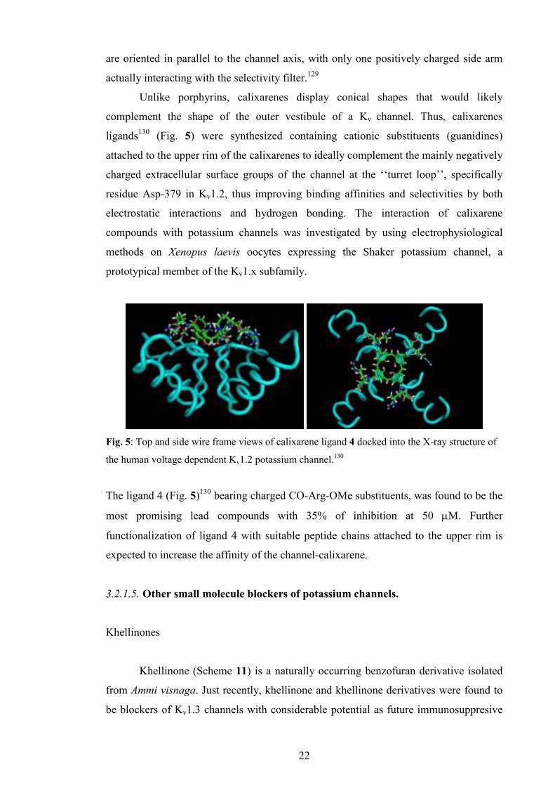
Unlike porphyrins, calixarenes display conical shapes that would likely
complement the shape of the outer vestibule of a Kv channel. Thus, calixarenes
ligands130 (Fig. 5) were synthesized containing cationic substituents (guanidines)
attached to the upper rim of the calixarenes to ideally complement the mainly negatively
charged extracellular surface groups of the channel at the ‘‘turret loop’’, specifically
residue Asp-379 in Kv1.2, thus improving binding affinities and selectivities by both
electrostatic interactions and hydrogen bonding. The interaction of calixarene
compounds with potassium channels was investigated by using electrophysiological
methods on Xenopus laevis oocytes expressing the Shaker potassium channel, a
prototypical member of the Kv1.x subfamily.
Fig. 5: Top and side wire frame views of calixarene ligand 4 docked into the X-ray structure of
the human voltage dependent Kv1.2 potassium channel.130
The ligand 4 (Fig. 5)130 bearing charged CO-Arg-OMe substituents, was found to be the
most promising lead compounds with 35% of inhibition at 50 µM. Further
functionalization of ligand 4 with suitable peptide chains attached to the upper rim is
expected to increase the affinity of the channel-calixarene.
3.2.1.5. Other small molecule blockers of potassium channels.
Khellinones
Khellinone (Scheme 11) is a naturally occurring benzofuran derivative isolated
from Ammi visnaga. Just recently, khellinone and khellinone derivatives were found to
be blockers of Kv1.3 channels with considerable potential as future immunosuppresive

23
agents. While khellinone itself only weakly blocks Kv1.3 it also serves as a versatile
starting material for at least two different classes of new Kv1.3 blockers131 that block
Kv1.3 channels and inhibit anti-CD3 activated T-cell proliferation at submicromolar
concentrations. The khellinones are indisputably a very promising group of potent Kv1.3
blockers that possibly contain future potent immunomodulating drugs. Since there has
been a significant rise of individual
khellinone derivatives with good Kv1.3
blocking activity, the next step in the search
of an ultimate drug candidate should be
modelling, QSAR and docking studies with
the assistance of structural information
(experimental or modelled) on Kv1.3
channels.
Anthranilic amides
Discovery of anthranilic amides as
potent blockers of Kv1.5 is an interesting
example of the so-called “pharmacophore
based search” for new lead compounds.132,133
The result was several promising compounds
having good potency (0.5-0.7 µM),
acceptable selectivity over Kv11.1 (HERG), whereas compound 8 (Scheme 12) had oral
bioavailability in animal model of 43%: therefore being a promising drug substance for
a new and safe treatment of atrial fibrillation.132,133
Correolide derivatives
Correolide (Scheme 13) is a nortriterpene isolated from the roots and bark of the
Costarican tree Spachea correa.134 The compound has a large, complex pentacyclic
triterpenoid, heavily oxygenated structure, displaying five acetoxy moieties and an
epoxide group. It was proven135 to be a highly potent, reversible blocker of Kv1.3
channel, the first small molecule inhibitor of Kv1 series potassium channels to be
isolated from a natural, plant source. Preliminary 86Rb+ efflux assay from CHO/Kv1.3
cells showed high potency IC50 value of 80 nM. One of the most important features of
O
OCH3
OH
O
Scheme 11: Structure of khellinone
N
O
NH
S
OO
N
Scheme 12: Molecule 8
24
correolide is an excellent selectivity over other members of the Kv1 family. That
characteristic made correolide a likely candidate as a new immunosuppressant.
However, the most serious obstacle for advancement of correolide towards drug
candidate status was the fact that correolide and its analogues also appear to inhibit
Kv1.1 channels present in some peripheral nerve terminals,136 thereby causing
acetylcholine release, which explains some of the limited toxicity observed in vivo with
this structural series. Another problem is the structure of correolide; its molecular
complexity makes organic synthesis of new analogues both challenging and expensive.
O
OAc
OAC
H
HH
O
OAc
OH
OAc
OAc
O
O
O
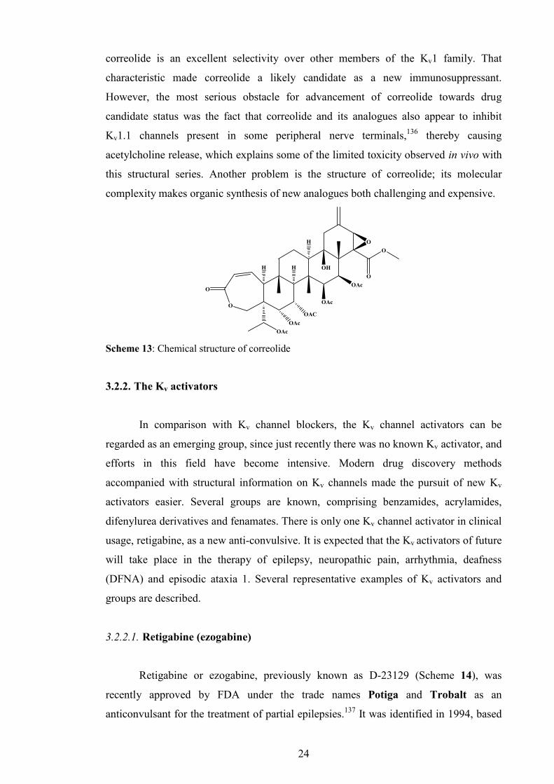
Scheme 13: Chemical structure of correolide
3.2.2. The Kv activators
In comparison with Kv channel blockers, the Kv channel activators can be
regarded as an emerging group, since just recently there was no known Kv activator, and
efforts in this field have become intensive. Modern drug discovery methods
accompanied with structural information on Kv channels made the pursuit of new Kv
activators easier. Several groups are known, comprising benzamides, acrylamides,
difenylurea derivatives and fenamates. There is only one Kv channel activator in clinical
usage, retigabine, as a new anti-convulsive. It is expected that the Kv activators of future
will take place in the therapy of epilepsy, neuropathic pain, arrhythmia, deafness
(DFNA) and episodic ataxia 1. Several representative examples of Kv activators and
groups are described.
3.2.2.1. Retigabine (ezogabine)
Retigabine or ezogabine, previously known as D-23129 (Scheme 14), was
recently approved by FDA under the trade names Potiga and Trobalt as an
anticonvulsant for the treatment of partial epilepsies.137 It was identified in 1994, based

25
on flupirtine, a centrally acting analgesic that was discovered to have anticonvulsive
activity.138 Retigabine was found to activate neuronal potassium channels in different
cell preparations.139,140 The channel targeted was later identified as a member of the
KCNQ channel, lately renamed the Kv7 channel.141 This channel has long been known
to control excitability of neuronal cells. Furthermore, mutation of the Kv7 channel
subunits has been identified in a hereditary epilepsy syndrome, benign familial neonatal
convulsions (BFNC).70
NH
HN
NH2
O
O
F
Scheme 14: Retigabine, ethyl-4-(4-fluorobenzylamino)-2-aminophenylcarbamate
Retigabine has been shown to activate human Kv7.2 and Kv7.3 expressed either
alone or as a heterotetramer in Xenopus oocytes, and it appears highly selective for
neuronal Kv7.2-Kv7.5 channels over cardiac Kv7.1, but it has much lower selectivity
among the neuronal family members.142-144 The exact molecular mechanism of
retigabine is Kv7.2 activation by binding of lipophilic fluorophenyl ring of retigabine to
tryptophan in the cytoplasmic end of S5 (W236) in Kv7.2 channel. Consequently, the
open form of Kv7.2 is stabilised.145 Retigabine is considered as the prototype KCNQ
activator and has the triggered pursuit of new Kv activators.
3.2.2.2. Benzamides and ICA-27243
Generally, several studies63,146-148 have shown that N-pyridylbenzamides or the
pyridinecarboxamide scaffold, where two aromatic moieties are linked via an amide
bridge, play a critical pharmacological role in the activation of potassium channels. It is
important to emphasize that the same scaffold was used in our structural research.
In series of studies63,146-148 simple N-pyridylbenzamides and
pyridinecarboxamides (Scheme 15), are found to be activators of BK potassium
channels. The BK potassium channels play a fundamental role in the regulation of the
tone of smooth muscle cells. Therefore, the availability of exogenous compounds able
to activate BK channels can guarantee an innovative pharmacological tool for the
clinical management of many pathological states, due to a cell hyperexcitability, such as

26
asthma, urge incontinence and bladder spasm,
gastric hypermotility, neurological and
psychiatric disorders. Examples of isolated BK
activators are shown in Scheme 15.
Recently, a report63 was published
about the discovery of a Kv7 channel activator
possibly representing a new class of Kv7.2
highly selective activators, with code name
ICA-27243 (Scheme 16). This new molecule
appears to be a selective activator of the
Kv7.2/3 channels. In human neuroblastoma
cells, ICA-27243 produced membrane
potential hyperpolarization that could be
prevented by co-administration with the M-
current inhibitors XE-991 and linopirdine. This
compound enhanced both 86Rb+ efflux (EC50 =
0.2 µM) and whole-cell currents in Chinese hamster ovary cells stably expressing
heteromultimeric Kv7.2/3 channels (EC50=0.4 µM). Activation of Kv7.2/3 channels was
associated with a hyperpolarizing shift of the voltage dependence of channel activation.
In contrast, the compound has no effect on cardiac Kv7.1 channels. The
compound was found to reversibly suppress seizure-like activity in an ex vivo model of
epilepsy and demonstrated in vivo anticonvulsant activity (ED50 = 8.4 mg/kg) in the
mouse maximal electroshock epilepsy model.
NH
N
O
Cl
F
Scheme 17: N-(5-chloropyridin-2-yl)-4-fluorobenzamide, ZTZ240
The next step in the quest for new Kv7.2/3 activators was a recent study32 that
revealed new types of benzamide, N-(5-chloropyridin-2-yl)-4-fluorobenzamide
(ZTZ240, Scheme 17), as an effective activator of Kv7.2/3. The potentiation of outward
current was dose-dependent, with a half-maximal value (EC50) of 5.8±0.9 µM and, more
dramatically, it slowed the deactivation. The molecular mechanism of the ZTZ240
N
NH
O
OH
Cl
NH
N
O
O
Cl
Scheme 15: Typical BK activators
N
O
N
H
F
F
Cl
Scheme 16: ICA-27243

27
effect is unique, mediated by specific molecular determinants, and hence consistent with
recognizing a new site.32
3.2.2.3. Acrylamides
An important group of Kv7 activators are the acrylamides or cinnamic amides.
The lead compound 8 ((S)-1, Scheme 18), has an improved pharmacokinetic profile and
is able to produce a remarkable increase (163±9%) in the Kv7.2 current at 10 µM (the
estimated EC50 value appears to be 6.0 µM).149 The compound (S)-1 enhances currents
through all human neuronal Kv7 channels expressed in Xenopus laevis oocytes150 with
partially stronger preference towards Kv7.4 and Kv7.5 subunits.
NH
O
N
O
NH
O
8 O
O
9
Scheme 18: Molecule 8 or (S)-1 ((S)-N-(1-[3-morpholin-4-yl-phenyl]-ethyl)-3-phenyl-
acrylamide) and 9 ((S)-N-(1-(benzo[d][1,3]dioxol-5-yl)-ethyl) )-3-phenyl-acrylamide).
The (S)-1 has hydrophobic binding site at S5 segment of Kv7.2 channel.
Interestingly, the stereoisomeric centre of (S)-1 plays a fundamental role in the
biological activity. Further lead optimisation efforts by restriction of the conformation,
led scientists to conformationally-resticted analogues include the methylene
dioxybenzene (compound 9 in Scheme 18), with an EC50 value on Kv7.2 of
approximately 20 nM (retigabine shows an EC50 of about 1 mM).151 A number of these
acrylamides have shown to have positive effects in vivo studies involving animal
models of migraine, anxiety and neuropathic pain. Further research on this group of
compounds potentially may bring new molecules that would have enhanced selectivity
toward particular member of Kv7 channel family with clinical use as therapy for BFNC,
DFNA2 or age-related deafness.
3.2.2.4. Diphenylurea derivatives
The diphenylurea group is a recently established group of Kv11.1 (HERG,
KCNH2) channel activators, potential anti-arrhythmia therapeutics suitable for
treatment of LQT2.152-154 This group comprises two members, NS1643152 and
28
NS3623153 (structures 10 and 11, Scheme 19). In the experimental model with
cardiomyocytes of guinea pig application of 10 µM of NS1643 activated Kv11.1 and
significantly decreased the action potential duration to 65% of the control values.
Exposure of Kv11.1 channels to NS3623 affected the voltage-dependent release from
inactivation, resulting in a half-inactivation voltage that is rightward-shifted by 17.7
mV.
Experiments154,155 explained the mechanism of action of diphenylurea
derivatives NS1643 and NS3623: they were found to be both activators and inhibitors of
Kv11.1 channels, e.g. partial agonist of Kv11.1 channels and that the mechanism of
activation is reduced channel inactivation. Another study156 found that NS1643 also
activates the Kv11.2 channel. Taken together, the present data strongly support the
concept of using Kv11.1 activators as a treatment for certain kinds of arrhythmias and
suggest further investigation of this new approach.
3.2.2.5. Fenamates
The fenamate group has the same N-phenylanthranilic acid structural basis,
however, regarding their pharmacological activity they are diverse; different members
possess Kv channel activation activity against different Kv channel types, including
Kv7.1, Kv7.2/3 and Kv11.1.
The fenamate scaffold has served as a template for the development of new Kv
channel modulators. Fenamates has been reported157 with two prominent members, lead
compound PD-118057 (12 in Scheme 20) and PD-307243 (13 in Scheme 20). PD-
118057 produced increase of 111.1±21.7% in the peak tail Kv11.1 current at 10 µM and
showed satisfactory selectivity and prevented action potential duration and QT
prolongation caused by dofetilide.
HN
HN
O
CF3 CF3
OH OH
HN
HN
O
NH
NN
N
F3C
Br
10 11
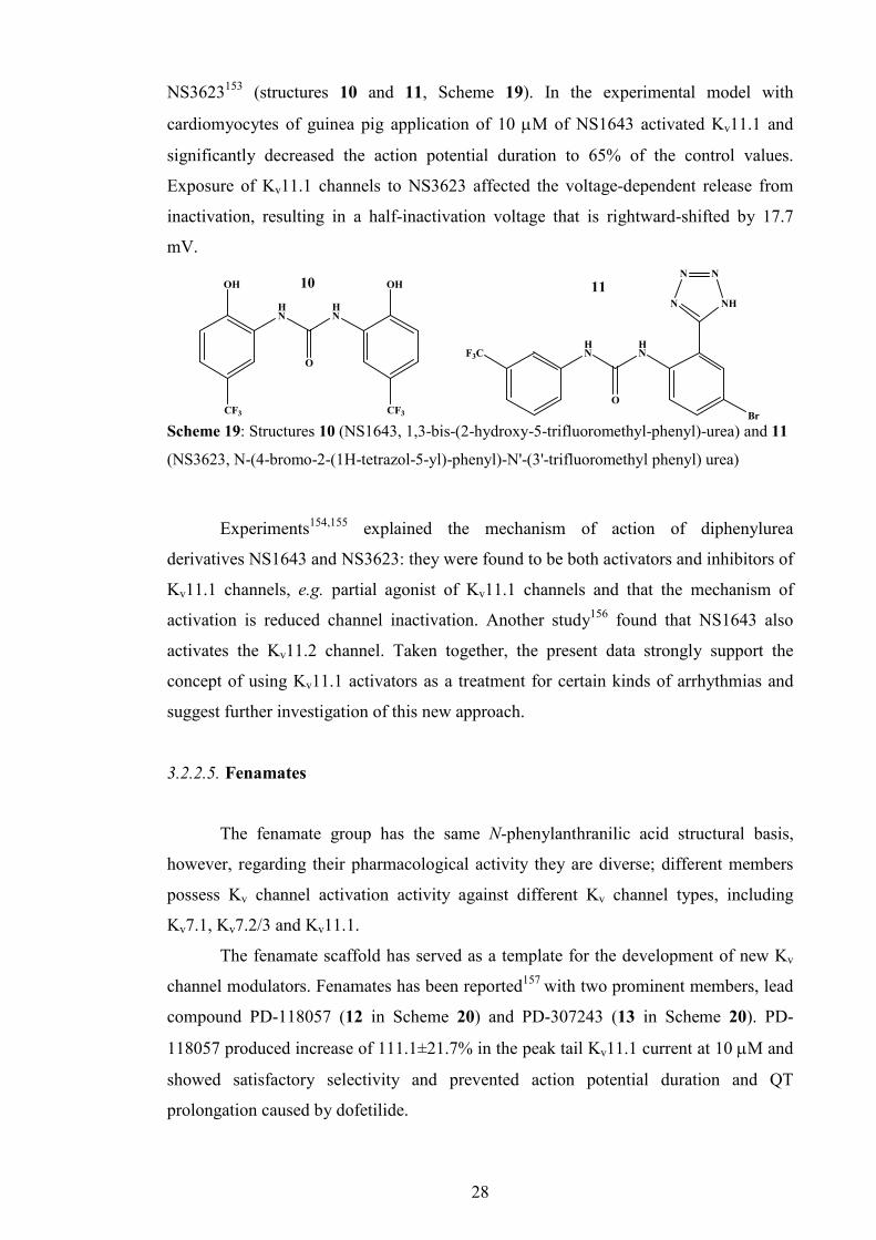
Scheme 19: Structures 10 (NS1643, 1,3-bis-(2-hydroxy-5-trifluoromethyl-phenyl)-urea) and 11
(NS3623, N-(4-bromo-2-(1H-tetrazol-5-yl)-phenyl)-N'-(3'-trifluoromethyl phenyl) urea)

29
The similar compound PD-307243 has been shown to increase the Kv11.1 tail
current by 58% at 1 µM; this was more potent than PD-118057. A recent study158
describes the mechanism of action of PD-307243. In experiments with Kv11.1, channel-
transfected CHO cells PD-307243 increased tail currents by slowing the channel
deactivation, but had no effect on channel activation, e.g. markedly slowed Kv11.1
channel deactivation and inactivation. Further optimisation could pave the way towards
new pharmaceuticals for patients with inherited or acquired long QT syndrome,
congestive heart failure, and diabetes.
3.2.2.6. Kv1.1 disinactivators
Another recent publication159 described a new chemically diverse class of Kv
activators (Scheme 21) that can be regarded as Kv1.1 disinactivators, compounds that
specifically target Kvβ1-mediated inactivation of Kv1.1 channels in the brain. This was
accomplished by testing compounds selected by high-throughput reverse yeast two
hybrid based primary screening (among 500,000 random compounds), structure
similarity searches, and engineering on Kv1.1/Kvβ1 channels. The identified compounds
blocked inactivation by several different mechanisms or sites of action, apparently
including direct and indirect mechanisms.
These disinactivators are the first small molecules reported to specifically
interfere with the protein–protein interaction of the Kv ball-and-chain N-type
inactivation process. It is likely that these disinactivators act directly on the Kvβ1 N-
terminus or its receptor site on Kv1.1, thus preventing it from blocking Kv1.1 channels.
They are effective in blocking seizure activity both in vitro and in vivo. Many of
the disinactivators are efficacious in the PTZ-induced seizure model, and some are also
active in the MES-induced seizure model. Small molecule Kv1.1 channel disinactivators
thus represent a new class of potential anticonvulsant drugs, and as such they may have
HN
OHO
N
HN
OHO
Cl
Cl
Cl
Cl
1312
Scheme 20: PD-118057 (12) and PD-307243 (13)

30
unique properties and usefulness in various diseases as epilepsy, episodic ataxia-1 and
neuropathic pain.
O O
Br NO2
O O
Br NO2
H
N
HN
O
O
O
O
Cl
14 15 16
N
HN
O
O
O
F
HN
O O
O2N
O1817
HN
O O
O
F3CHN
O O
O
CF3
Cl
19 20
Scheme 21: Structures of Kv1.1 disinactivators: cyclohexadiones (14, 15), hydantoins (16, 17)
and 1,3-dione-2-carboxamides (18, 19 and 20)
4. Summary
The therapeutical needs for Kv channels modulators are still to be answered,
bringing both potent and selective compounds. This is especially important for the
peripheral neural Kv channels involved in pathophysiology of multiple sclerosis and
spinal cord injuries. Currently, extracellular Kv blockers do not meet desired
requirements regarding the potency, selectivity, and toxicity. Furthermore, internal
blockers, based on 4-AP are still in basic development and future screening of many
libraries of potential derivatives are still mandatory. The carbamate53 and
benzamide63,146-148 blockers provide a solid ground for expansion of libraries involving
both simple and advanced derivatives. Also, new approaches have to be explored in
order to develop and design new scaffolds that might be a basis for the design of new,
extracellular blockers of potassium channels.

31
Compound libraries for targeting of Kv channels formed on basis of isomer grids
can be used for extensive structural systematic studies involving solid state
investigation, ab initio molecular modelling and conformational analysis. This quest is
not directly related to pharmacological success of a particular drug candidate, but rather
uses drug-like compound libraries and the concept of isomer grids as a tool for an
independent structural systematics survey. Therefore, the purpose of this study is to
synthesise benzamide, pyridinecarboxamide and carbamate isomer grids, characterise
them spectroscopically, determine their molecular and crystal structure, investigate their
optimised structures, perform conformational analysis, correlate solid state structures
with the modelled ones analysing differences and patterns as well as analysis and
correlations of solid state crystal packing with physico-chemical properties. Finally,
another important task is to explore and develop new scaffolds for future extracellular
targeting of potassium channels.

32
CHAPTER I: BENZAMIDES
AND PYRIDINECARBOXAMIDES

33
1. Benzamides 1.1. Mxx isomer grid 1.1.1. General description of synthesis
The classical nucleophilic acyl substitution reactions (Schotten–Baumann,
Scheme 22) between the 4-, 3- or 2-aminopyridines and 4-, 3- or 2-toluoyl chlorides
were used to produce a set of the nine methyl-N-(pyridinyl) benzamides (Mxx) (where x
= para-/meta-/ortho-). Reactions were performed in anhydrous conditions in CH2Cl2
(under N2), initially at 5°C and then at room temperature. A by-product was HCl, and
Et3N was employed, to move the reaction equilibrium towards the product; in total, one
molar equivalent of Et3N was added. The 4-, 3- or 2-aminopyridine (0.9411 g, 10.0
mmol) was added to a 250 ml round bottom flask placed on an ice bath with stirring.
Then, 30 ml of solvent (CH2Cl2) was added to the flask, followed by addition of Et3N
(1.5 ml, 10.76 mmol). Finally, the 4-, 3- or 2-toluoyl chlorides (~1.5 ml, 11.0 mmol)
were added in excess directly into the solution mixture. The reaction mixture was
allowed to warm to room temperature and stirred overnight.
The standard washing was the same for all groups of compounds: the organic
reaction phase was washed with 30 ml of KHCO3 (0.1 M) solution ca. 3-7 times. Then,
1.5 g of anhydrous MgSO4 was added to the organic solutions for 20 minutes. The flask
contents were filtered through a Büchner funnel (under vacuum) to remove MgSO4. The
filtrate was evaporated under vacuum and the product dissolved in minimal volumes of
warm CHCl3. A saturated solution was placed on ice and re-crystallization induced. The
resulting product was dried overnight and weighed. Silica was used as the stationary
phase and mixture of CHCl3, ethyl acetate and cyclohexane (4:2:1) was used as the
mobile phase.
Table 6: Quantities, yields and melting points of Mxx compounds Mxx m/g yield/% m.p./ºC Mpp 0.662 31.1 180.2-180.8†
Mmp 0.235 11.1 73.8-74.5‡
Mop 0.412 19.4 128.6-129.1 Mpm 0.416 19.5 128.2-128.8*
Mmm 1.490 70.0 90.0-91.0 Mom 0.903 42.5 107.5-108.5 Mpo 0.581 39.6 104.0-106.0 Mmo 0.498 37.6 78.8-80.0 Moo 0.504 38.2 115.0-117.1
† lit. 178.5-181°C28; ‡ partial melting, total melting occurs at 106.7°C; *lit.126.5°C27

34
N
NH2
N
NH2
N
NH2
NH
NO
NH
N
O
NH
N
O
N N
O
O
H3C
H3C
H3C
H3CCH3
A. p/m/o-CH3C6H4COCl
Et3N, CH2Cl2
p/m/o-CH3C6H4COCl
Et3N, CH2Cl2
p/m/o-CH3C6H4COCl
Et3N, CH2Cl2
B. p/m/o-CH3C6H4COCl
C. p/m/o-CH3C6H4COCl
CH2Cl2
2-Aminopyridine (2-AP)
3-Aminopyridine (3-AP)
4-Aminopyridine (4-AP)
Mxp
Mxm
Mxo
Mxod
A: 4%, B: 14%, C: 50%
A: 96%, B: 86%, C:50% Scheme 22: The synthesis of the Mxx isomer grid and Mxod by-products
Since the purity of 3-aminopyridine was poor, column chromatography was
employed for the Mxm compounds with success. This procedure was appropriate for
the first six isomers (Mxp and Mxm), however, if 2-aminopyridine was used the
products were almost exclusively imides, 4-/3-/2-methyl-N-(4-/3-/2-toluyl)-N-(pyridin-
2-yl) benzamides (Mxod). The formation of imides with 2-aminopyridine has been well
described,160-162 and depends on the ortho-pyridine nitrogen atom that destabilises and
weakens the neighbouring N-H bond, with a second substitution by an acyl moiety
yielding the Mxod series, depending on the reaction conditions.163,164
Exclusion of the Et3N improved formation of Mxo but not in sufficient ratio
(14% of Mxo). Finally, the Mxo compounds were synthesised by performing the
reaction without solvent and Et3N by simply mixing 2-aminopyridine and toluoyl
chlorides in a round bottom flask until a crude product is formed, containing 50% of
Mxo and 50% Mxod. After standard washing, separation of the compounds was
performed using column chromatography.

35
In most cases, yields were modest to good (19-70%), with the exception of Mmp
(11%). All Mxx products are white, odourless, crystalline solids, insoluble in water, but
readily soluble in organic solvents such as CH2Cl2 and CHCl3, though less so in
cyclohexane and isopropyl alcohol. The Mxx isomer characterisation data show a
degree of modularity and patterns will be discussed below. Spectroscopic data including 1H-NMR, 13C-NMR and IR are listed in Appendix I (Sections 1.1), while the spectra are
shown in the ESI I (Section 1.1)
1.1.2. General materials and equipment
All chemicals, including reagents, solvents and supplies were purchased from
Sigma Aldrich except for 2-pyridinoyl chloride (Fluorochem). TLC alumina and silica
plates were purchased from Fluka. Melting points were analysed using a Stuart
Scientific SMP40 automated melting point apparatus. The solid state IR spectroscopy
was performed using the attenuated total reflection (ATR) method on a Perkin-Elmer
Spectrum 100 FT-IR Spectrometer. NMR spectroscopy was performed on Bruker
BioSpin UltraShield NMR spectrometers at 293±1 K, operating at 400 or 600 MHz for 1H, 100.62 MHz for the 13C (on both instruments) and 376.46 MHz for 19F resonances
(on 400 MHz only). The 1H spectra were recorded in two solvents: in CDCl3 and
DMSO-d6 (in CDCl3 and acetone-d6 for carbamates) while the 13C and 19F spectra were
only recorded in DMSO-d6 (acetone-d6 for carbamates); in CDCl3 and while the 13C
spectra were only recorded in acetone-d6. The NMR chemical shifts values (δ) are
expressed in ppm and referenced to TMS (Cl3FC for 19F NMR) and coupling constants
(J) are quoted in Hz. Ab initio molecular modeling and conformational analysis for the
gas phase was performed at the B3LYP/6-311++G level using the Gaussian 0325
package (version E.02) for the MS Windows XP SP3 operating system running on a PC
(Intel Core i7-940 2.93 GHz, 8GB). The solvated form computations (PCM-
SMD/B3LYP/6-311++G), conformational analyses and high accuracy energy (CBS-
QB3) calculations were undertaken using Gaussian 0925 for Linux/Unix operating on a
Bull Novascale R422-E2 system provided by the Irish Centre for High-End Computing.
1.1.2. e
1.1.3. X-ray crystallography methods
The single crystal X-ray data for eight Mxx isomers were collected on an Enraf-
Nonius κ-CCD diffractometer at 150(1) K and for Mpo on a Bruker ApexII: θ range

36
from 2-27.5° with 100% data coverage to 25°.165,166 Data reduction procedures are
standard and details have been published previously.167 All structure solutions were
obtained using the SHELXS97 direct methods program and refined by full matrix least
squares calculations on F2 with all non-H atoms having anisotropic displacement
parameters (except for the minor component C in Mop).3 The H atoms were treated as
riding atoms in SHELXL97 (150 K defaults) except for the amide N-H (isotropic
refinement) using the OSCAIL suite of programs168 with selected crystallographic and
structural data in Tables 7 and 8 and in the ESI I (Section 2.1). Molecular and hydrogen
bonding diagrams were generated using Mercury or PLATON (Figs. 6-11).169 All CSD
searches on the Cambridge Structural Database (CSD) were performed with the
November 2009 release (version 5.31).8
1.1.4. Computational methods
Ab initio calculations have been used to predict and optimize the nine methyl-N-
(pyridyl)benzamide (Mxx) structures and energies, both in gas phase and solvated
forms (CH2Cl2 and H2O) to ascertain the energetically preferable conformations, global
minima and rotational energy barriers between conformations.25 The nine Mxx isomer
structures were generated using GaussView with optimizations performed using the
B3LYP/6-311++G method. Optimizations using CH2Cl2 (non-polar) or H2O (polar)
were performed using the PCM-SMD model170 in Gaussian 09.
The Mxx compounds contain two aromatic rings linked by the amide group. A
total of four distinct conformations are possible for the aromatic N atom and methyl
group positions relative to the amide: this is relevant for Mxx isomers with a meta-
/ortho-pyridine N atom or CH3 group (Scheme 23). The rings can have syn (P-syn or
M-syn) or anti (P-anti, M-anti) conformations (Scheme 23): logically Mpp is not
subject to this convention.
NH
O
YZ
ZY
H3C
CH3
P-syn
M-syn
P-anti
M-anti
Scheme 23: The four possible Mxx conformations Conformational analysis was performed by rotation of the C16-C11-C1=O1 (α
dihedral, Mx-ring) and C26(N22)-C21-N1-C1 dihedral angles (β dihedral, p/m/o-

37
pyridine ring), respectively, by 5° increments from their optimised points through
±180°. Local relaxation (optimisation) was performed at every point and single point
energies were calculated using the methods and basis sets detailed above. Potential
energy surface (PES) diagrams were obtained where energy values are plotted against
dihedral angle (°) in Figs. 7 and 8. Differences (∆θ) between the α and β dihedral angles
and corresponding solid-state angles marked (•) can be ascertained in each isomer PES
diagram for comparison purposes. The ∆θ represents the deviation of the solid-state
angle from the optimised angle as a basis point.
In addition, high accuracy energies including electronic energy and Gibbs free
energy values were calculated using the Complete Basis Set (CBS-QB3) compound
method171 (ESI I, Section 3.1.1). Absolute energies are expressed in Hartrees, while
relative energies are expressed in kJ.mol-1.
1.1.5. Molecular and crystal structure data
The principal intermolecular feature for eight of the Mxx crystal structures (x =
para-/meta-/ortho) is that they aggregate in the solid-state via N-H···Npyridine hydrogen
bonds, but in different space groups. The O=C carbonyl group only participates in weak
intra- and intermolecular C-H···O contacts in the majority of structures. Only for the
Mpm structure is the N-H···O=C interactions the primary hydrogen bonding feature.
However, in the Mxo series cyclic R22(8) rings of N-H···N intermolecular interactions
are the main hydrogen bonding feature.
Table 7: Selected crystallographic data for the nine Mxx isomers†
Mxx Space group Z’ Volume (Å3) R-factors Mpp P21/n 1 1038.49(12) 0.066, 0.202 Mmp P̅1 2 1056.41(16) 0.066, 0.183
Mop Pc 2 1123.65(12) 0.056, 0.161 Mpm P1 4 1071.37(8) 0.059, 0.154 Mmm P̅1 2 1079.21(9) 0.076, 0.254
Mom Pca21 1 1109.94(5) 0.041, 0.096 Mpo P̅1 1 525.04(5) 0.039, 0.109
Mmo P21/c 1 1065.04(15) 0.065, 0.195 Moo P̅1 1 546.42(6) 0.063,0.184
† Complete crystallographic, refinement and structural details for all nine Mxx isomers
(C13H12N2O) are listed in the ESI I (Section 2.1).
The N-H···N interactions form C(6) chains in the Mxp series, C(5) chains in
Mmm, Mom and cyclic R2
2(8) hydrogen bonded rings in the Mxo triad. In Mpm,
amideN-H···O=C interactions form classical C(4) chains. Diagrams highlighting the main

38
features are presented in Figs. 6-11 and salient features of the nine Mxx structures are
provided in Tables 1 and 2. The α, β torsion angles for each Mxx isomer are plotted
with gas-phase conformations (Fig. 12).
1.1.5.1. Mxp isomer series
Mpp molecular and crystal structure
Apart from rotational disorder in the CH3 group, the molecular structure is as
expected for benzamides. The crystal structure in space group P21/n is similar to the
reported Fpp162 structure in terms of the N-H···Npyridine bonding (N···N is 3.105(3) Å)
and is isostructural with the series of five molecules in Table 5.172
Fig. 6: An ORTEP diagram of Mpp
It is not isomorphous with Fpp but for the a b, c cell swop (Unit cell parameters
for Fpp = a = 5.65, b = 11.39, c = 15.43 Å, β = 95.60°; transformed unit cell parameters
for Mpp = a = 5.70, b = 16.89, c = 11.34 Å, β = 107.88°).
Fig. 7: The primary N-H···N hydrogen bonding along the c-axis direction in Mpp and
isostructural with the related fluoro derivative Fpp

39
The N-H···Npyridine hydrogen bonding dominates the primary interactions in the
Fxp structures where the pyridine N atom is para-substituted. Mpp (Fig. 6) differs from
Fxp by having a CH3 group and the parent benzamide in Table 5.172 The N-H···N
interactions in Mpp form a one-dimensional chain along the c-axis direction as C(6)
chains (and parallel to the [1̄01] plane) and augmented by weak C-H···O and C-
H···π(arene) interactions involving the C26-H26 atoms. The C6/C5N interplanar angle is
46.03(9)°.
Mmp molecular and crystal structure
The Mmp structure crystallizes in P̅1 with Z’ = 2 and with differences between
the O1-C1-C11 angles of [121.2(2)°, 119.7(2)°] and C1-N1-C21 [127.6(2)°, 125.5(2)°]
for molecules A and B, respectively. Torsion angle differences of ca. 8° are evident by
different A, B molecular data values for C1-N1-C21-C22 of 12.9(4)°, 20.2(4)°,
respectively. Aggregation is driven by N-H···Npyridine hydrogen bonding. This involves
alternating A/BN···NB/A distances of 3.058(3), 3.059(3) Å, but with N-H···N angles of
142(3)° (for A→B), 172(3)° (for B→A). This highlights the strain and distortions in
incorporating two molecules within the asymmetric unit and with the molecular packing
as the A→B molecules link by C(6) chains and vice versa. The two N-H···N hydrogen
bonds combine and aggregate as a one-dimensional column parallel to the (110) plane.
Table 8: Salient structural features in the nine Mxx isomers†
Mxx C6/C5N (°) C6/amide C5N/amide N···N/O (Å)‡ Packing Mpp 46.03(9) 28.99(11) 17.40(13) 3.105(3) 1-D chains Mmp 4.84(15)
5.47(12) 15.70(13) 19.88(10)
10.94(13) 17.73(9)
3.058(3) 3.059(3)
2-D sheets
Mop 81.79(15) 81.58(14)
54.60(17) 54.85(15)
28.34(17) 27.96(16)
2.952(5) 2.950(5)
1-D chains
Mpm* 65.13(11) 64.04(10)
1.5(2) 1.9(2)
29.45(15) 29.70(15) 24.47(16) 24.79(16)
35.83(14) 34.57(13) 24.16(16) 24.79(16)
3.029(6) 3.016(5) 3.085(6) 3.085(5)
1-D chains
Mmm 55.57(10) 65.70(10)
25.55(8) 36.43(10)
31.33(14) 29.54(14)
2.998(4) 3.006(4)
1-D chains
Mom 71.20(5) 57.33(6) 13.91(10) 2.946(2) 1-D chains Mpo 45.34(4) 35.93(5) 17.51(8) 3.1081(15) Dimers Mmo 70.55(7) 35.99(8) 35.05(11) 3.106(3) Dimers Moo 84.79(5) 77.28(6) 10.93(10) 3.076(3) Dimers † Full structural details are in the ESI I (Section 2.1).
‡ The primary amideN-H···Npyridine or N-H···O=C* interaction distances.

40
These 1-D columns interlock with symmetry related columns along the c-axis
direction forming 2-D sheets via C-H···O interactions (involving C17A). The 3-D
crystal structure assembles between parallel sheets with weak interactions via C-H···O
(involving C23A) and short C-H···π(arene) interactions involving
C25A···[C11B,…,C26B], with a H25A···Cg distance of 2.65 Å, where Cg is the
aromatic ring centroid. Unlike the Mpp structure, the C6/C5N interplanar angles are
essentially co-planar at 4.84(15)°, 5.47(12)° for molecules A and B, respectively.
Mop molecular and crystal structure
Mop crystallises in Pc with Z’ = 2 and with molecular disorder in one of the
molecules. The solution of the Mop structure failed in space group P21/c despite the
systematic absences indicating that this was a favourable choice. However, attempts to
solve and refine in both Pc and P21 proved successful. The Pc structure provides the
better solution and refinement to an R-factor of 0.076, a WGHT card of 0.14 and
residual electron density for the top 26 peaks of +0.57 e.Å-3 to +0.26 e.Å-3 and
indicating possible molecular disorder at molecule A. Refinement of these residual
peaks as sensible chemical sites as a minor conformation of molecule A labelled as C
drops the R-factor from 0.076 to 0.057 and a final R-factor of 0.056, WGHT of 0.09 and
a range of residual electron density from +0.18 e.Å-3 to -0.20 e.Å-3. The minor
component C has 10.1(6)% site occupancy and occupies the same molecular volume
element as the major A sites. Of the nine Mxx isomers the volume of the Mop is the
largest and this is almost certainly due to the disordered A/C component.
Molecules A and B are identical and with practically no differences in molecular
geometric data. The only difference between the two molecules is the disorder (A/C) at
the molecule A location. The N-H···Npyridine interactions (intermolecular N···N distances
of 2.952(5) Å, 2.950 Å) dominates the hydrogen bonding with additional C-H…O
contacts. The N···N interactions aggregate as A/C→A/C and B→B molecules in C(6)
zig-zag chains and parallel to the (̅102) plane. The C6/C5N planes are almost orthogonal
and due to the steric hindrance from the ortho-methyl groups and are at angles of
81.79(15)° and 81.58(14)°. Differences between the major orientation (A) and molecule
(B) for C1-N1-C21-C22 are -155.2(4)° and -27.4(6)°.

41
1.1.5.2. Mxm isomer series
Mpm molecular and crystal structure
Mpm crystallizes with 4 molecules in P1. The crystallization of four molecules
in P1 is unusual (Fig. 8) but all four molecules differ in their molecular conformations
and can be distinguished as two distinct sets with molecules A, B and C, D, whereby the
C6/C5N interplanar ring angles are oriented at angles of ca. 65° for molecules A, B at
[65.13(11)°, 64.04(10)°] (with differences > 3σ) and close to co-planarity at 0° in C, D
at [1.5(2)°, 1.9(2)°]. The bond lengths and angles are normal and are all similar and <3σ
level for the related geometric data. However, there are subtle differences in the torsion
angles and intermolecular hydrogen bonds. For example with respect to distances across
the molecules [intramolecular distances], the N23···C17 molecular distances vary and
differ from 10.134(6) Å (in A), 10.118(6) (in B), 9.985(6) Å (in C) to 9.940(6) Å (in D),
a difference of 0.2 Å.
The molecules aggregate as A···A···, B···B··· etc. 1-D chains via four separate
and distinct N-H···O=C interactions and along the b-axis (010) direction with N···O
distances of 3.029(6), 3.016(5), 3.085(6) and 3.085(5) Å for molecules A to D,
respectively. Apart from weak C-H···π(arene) contacts – these are the primary
interaction in the crystal structure. Two weak CH3···Npyridine interactions with H···N 2.60
Å and angles of 159°/156° are also present involving C to D and D to C linking the
independent C, D chains in two-dimensions. Mpm is unusual in that it is the only Mxx
molecule which crystallizes with N-H···O=C as the primary interaction and not N-
H···Npyridine and given its unusual Z’ = 4 in P1 should at some stage be the subject of a
thorough variable temperature study.
Fig. 8: The four molecules (A) to (D) in the asymmetric unit of Mpm.

42
The crystallization of four molecules in the asymmetric/unit cell is interesting in
the absence of disorder and with clear and subtle distinctions between the four
molecules (there are NO matrix correlation coefficients above 0.5). A solution can be
obtained in space group P̅1 (No. 2), but one of the molecules is disordered and the R-
factor remains stubbornly high and at R = 0.2.
Mmm molecular and crystal structure
The Mmm structure crystallizes in P̅1 with Z’ = 2 with the two molecules
differing by 10° in their corresponding dihedral angles. For example the C6/C5N
interplanar angles are 55.57(10)° and 65.70(10)° in molecules A and B while the O1-
C1-C11-C16 angles are 156.8(3)° and 146.1(3)°, for A and B, respectively. It is a non-
merohedral twinned crystal and there is no discernible disorder in the molecular
components. Molecules aggregate via A/BN-H···NB/A hydrogen bonding as C(5) chains
along the b-axis or (010) direction [at distances of 2.998(4) Å and 3.006(4) Å]. Two C-
H···π(arene) interactions are present involving C22A and C22B. Of the carbonyl O
atoms, only O1B is involved in a weak CH3···O=C interaction. Both A and B molecules
have their P-ring in the P-anti conformation, while both M-rings are M-syn.
Mom molecular and crystal structure
The Mom structure crystallizes in Pca21 with Z’ = 1. The primary interaction is
the N-H···Npyridine intermolecular interaction forming 1-D C(5) chains along the a-axis
direction with a N···N distance of 2.946(2) Å and two C-H···O interactions complete the
interactions. There is also a weak C-H···π(arene) interaction. The C6/C5N rings are
mutually oriented at 71.20(5)°. This is one of the most regular of the Mxx structures
without disorder, twinning or potential pseudosymmetry problems. As in Mmm the P-
ring is in the P-anti conformation.
1.1.5.3. Mxo isomer series
The primary hydrogen bonding in all three Mxo derivatives is cyclic,
symmetrical (amide)N-H···N(pyridine) with graph set R22(8) that is remarkably similar for all
three Mxo structures. In tandem with this hydrogen bonded ring there are also intra- and
intermolecular C-H···O=C contacts present. The principal difference between all three

43
structures is the presence of an intra-dimer C-H···π(arene) interaction which is shortest
in Moo. Mpo, Mmo, Moo are isostructural but they are not isomorphous.
Mpo molecular and crystal structure
The cyclic hydrogen bonded dimer (Fig. 9) forms about inversion centres with
an N···N distance of 3.1081(15) Å. The dimers are further linked into a 1-D zig-zag
chain via C-H···O interactions about inversion centres and parallel to the (112̄) plane.
Chains stack and are linked via weak contacts. The shortest C-H···π(arene) contacts
have C···Cg distances of 3.5556(14) and 3.7056(14) Å with C-H···Cg angles of 123°,
134° and too long to be a meaningful interaction. The room temperature study of Mpo
(XIFNIK8) has been reported and archived. Mpo is similar to XIFNIK8 and only differs
in interaction data due to the difference in the experimental data collection temperature.
The interplanar angle between the C6 and C5N rings is 45.34(4)°.
Fig. 9: The primary hydrogen bonding in Mpo with the cyclic N-H···N dimers.
Mmo molecular and crystal structure
The cyclic hydrogen bonded dimer forms about inversion centres with an N···N
distance of 3.106(3) Å. Dimers are arranged and linked via weak C-H···O and C-
H···π(arene) contacts. The interplanar angle between the C6 and C5N rings is 70.55(7)°.
The major difference between Mpo and Mmo is the angle of the intradimer C-
H···π(arene) contact.
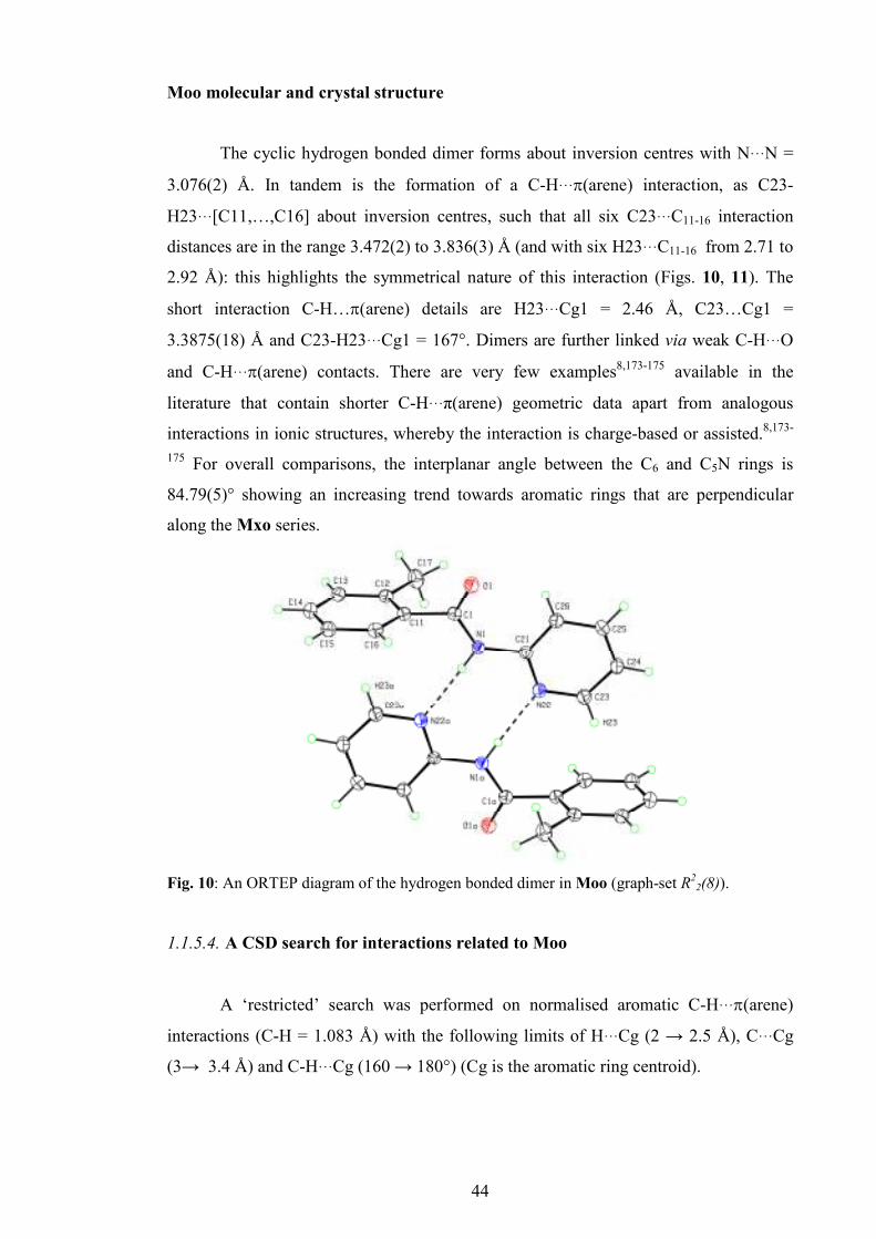
44
Moo molecular and crystal structure
The cyclic hydrogen bonded dimer forms about inversion centres with N···N =
3.076(2) Å. In tandem is the formation of a C-H···π(arene) interaction, as C23-
H23···[C11,…,C16] about inversion centres, such that all six C23···C11-16 interaction
distances are in the range 3.472(2) to 3.836(3) Å (and with six H23···C11-16 from 2.71 to
2.92 Å): this highlights the symmetrical nature of this interaction (Figs. 10, 11). The
short interaction C-H…π(arene) details are H23···Cg1 = 2.46 Å, C23…Cg1 =
3.3875(18) Å and C23-H23···Cg1 = 167°. Dimers are further linked via weak C-H···O
and C-H···π(arene) contacts. There are very few examples8,173-175 available in the
literature that contain shorter C-H···π(arene) geometric data apart from analogous
interactions in ionic structures, whereby the interaction is charge-based or assisted.8,173-
175 For overall comparisons, the interplanar angle between the C6 and C5N rings is
84.79(5)° showing an increasing trend towards aromatic rings that are perpendicular
along the Mxo series.
Fig. 10: An ORTEP diagram of the hydrogen bonded dimer in Moo (graph-set R22(8)).
1.1.5.4. A CSD search for interactions related to Moo
A ‘restricted’ search was performed on normalised aromatic C-H···π(arene)
interactions (C-H = 1.083 Å) with the following limits of H···Cg (2 → 2.5 Å), C···Cg
(3→ 3.4 Å) and C-H···Cg (160 → 180°) (Cg is the aromatic ring centroid).

45
Fig. 11: The Moo ‘dimeric’ unit with N-H···N and C-H···π(arene) intermolecular interactions.
For version 2.30 + 4 updates a total of 41 ‘hits’ were obtained (of which 38
contain a metal): a total of 51 ‘hits’ are obtained when ‘normal’ bond lengths of C-H =
0.95 Å are used. The majority of these ‘hits’ are organometallic/metal-organic and are
intramolecular in nature and principally due to the orientation of the aromatic ring
towards another aromatic ring within the same molecule and typically separated by 5-7
bonds. The search was conducted to find short, symmetrical C-H···π(arene) interactions.
In Moo with C23-H23 normalised to 1.083, the short interaction details are H23···Cg1 =
2.33 Å with C23-H23···Cg1 = 166°. The range of H23···[C11,…,C16] distances span
from 2.61 to 2.80 Å.
The CSD codes for structures with short intermolecular C6-H···π(C6) interactions
include ICEXUJ (a Zr complex) and LEXJOO (Au derivative): whereas in LETYUE the
solvent is disordered with large displacement ellipsoids. In ICEXUJ, the geometric data
are 2.32 Å, 3.373 Å, 163, involving indenyl group C6 rings, whereas, in LEXJOO or
triphenylphosphine-(3H-5-phenyl-1,2,3-triazol-4-yl)-gold(I) the geometric data are even
shorter with data of 2.26 Å, 3.303 Å, 161° and this interaction forms in tandem with the
‘tight’ N-H···N interaction between the triazole moieties. The Moo data are comparable
to the geometric data in these structures.
Examples with intramolecular interactions include both QEZRAO (2.25 Å, 3.32 Å,
171°) and TEGJOF (2.23 Å, 3.31 Å, 178°), which with WIXHIV (2.20 Å, 3.26 Å, 168°)
are where the H atom direction is constrained by ligand geometry and steric bulk. In
VAGFIS10 the interaction is constrained by the geometrical demands within the
molecule. In Moo the interaction is intermolecular in nature and comparable in
geometric terms with the shortest analogous C-H···π(arene) intramolecular interactions
present in metal complexes (Figs. 10, 11).8,173-175
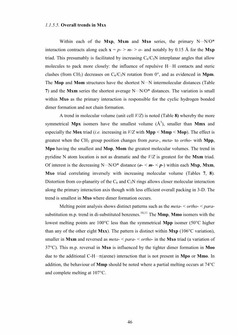
46
1.1.5.5. Overall trends in Mxx
Within each of the Mxp, Mxm and Mxo series, the primary N···N/O*
interaction contracts along each x = p- > m- > o- and notably by 0.15 Å for the Mxp
triad. This presumably is facilitated by increasing C6/C5N interplanar angles that allow
molecules to pack more closely: the influence of repulsive H···H contacts and steric
clashes (from CH3) decreases on C6/C5N rotation from 0°, and as evidenced in Mpm.
The Mop and Mom structures have the shortest N···N intermolecular distances (Table
7) and the Mxm series the shortest average N···N/O* distances. The variation is small
within Mxo as the primary interaction is responsible for the cyclic hydrogen bonded
dimer formation and not chain formation.
A trend in molecular volume (unit cell V/Z) is noted (Table 8) whereby the more
symmetrical Mpx isomers have the smallest volume (Å3), smaller than Mmx and
especially the Mox triad (i.e. increasing in V/Z with Mpp < Mmp < Mop). The effect is
greatest when the CH3 group position changes from para-, meta- to ortho- with Mpp,
Mpo having the smallest and Mop, Mom the greatest molecular volumes. The trend in
pyridine N atom location is not as dramatic and the V/Z is greatest for the Mxm triad.
Of interest is the decreasing N···N/O* distance (o- < m- < p-) within each Mxp, Mxm,
Mxo triad correlating inversely with increasing molecular volume (Tables 7, 8).
Distortion from co-planarity of the C6 and C5N rings allows closer molecular interaction
along the primary interaction axis though with less efficient overall packing in 3-D. The
trend is smallest in Mxo where dimer formation occurs.
Melting point analysis shows distinct patterns such as the meta- < ortho- < para-
substitution m.p. trend in di-substituted benzenes.10,11 The Mmp, Mmo isomers with the
lowest melting points are 100°C less than the symmetrical Mpp isomer (50°C higher
than any of the other eight Mxx). The pattern is distinct within Mxp (106°C variation),
smaller in Mxm and reversed as meta- < para- < ortho- in the Mxo triad (a variation of
37°C). This m.p. reversal in Mxo is influenced by the tighter dimer formation in Moo
due to the additional C-H···π(arene) interaction that is not present in Mpo or Mmo. In
addition, the behaviour of Mmp should be noted where a partial melting occurs at 74°C
and complete melting at 107°C.

47
1.1.6. Ab initio calculations
1.1.6.1. Structure optimisation
The three torsion angles that define the most important conformation angles of
the Mxx isomers (optimised in gas phase and solvated as CH2Cl2, H2O) are detailed in
the Table 9. The torsion angles are aromaticC-C-C=O (α) between the toluoyl ring and
amide group (equivalent to the C16-C11-C1=O1 solid-state angle), C-N-C-Caromatic (β)
between the pyridine ring and amide group (equivalent to the C26(N22)-C21-N1-C1
angle) and the O=C-N-C amide linkage angle (δ).
In general, all calculated Mxx structures are partially planar with the α torsion
angles deviating from co-planarity. Moreover, the α angle in Mox is smaller than in the
Mpx, Mmx series due to the sterically repulsive interaction between the CH3 group and
C=O group (M-anti conformation) as seen in the Mxo crystal structures.
Table 9: Torsion angles (°) of the optimised Mxx structures a optimised in gas phase optimised in CH2Cl2 optimised in H2O
α β δ α β δ α β δ
Mpp 153.29 -3.22 -4.76 152.24 -5.23 -4.12 152.34 -8.89 -4.88Mmp 152.58 -2.95 -4.73 151.88 -3.73 -4.35 152.86 -5.76 -3.92Mop 135.27 -2.19 -4.24 131.33 -2.50 -4.19 128.73 -2.13 -3.46Mpm 153.50 -3.00 -4.39 152.26 -5.77 -3.82 152.50 -12.15 -4.36Mmm 152.81 -2.94 -4.33 151.94 -4.08 -3.92 152.80 -8.01 -2.88Mom 134.94 -1.96 -3.94 130.89 -2.54 -3.79 127.80 -4.97 -2.92Mpo 156.74 -1.88 -3.94 153.07 -4.66 -3.34 153.61 -5.11 -4.06Mmo 155.95 -1.71 -4.04 153.73 -1.86 -3.26 152.17 -5.58 -3.99Moo 137.12 -1.19 -3.98 132.61 0.37 -4.45 128.63 -1.28 -2.91a The angle C16-C11-C1=O1 is referred as α, the angle C26(N22)-C21-N1-C1 as β and O1=C1-
N1-H1 angle (amide link) as δ. All geometries are based on B3LYP/6-311++G optimizations
with or without the PCM-SMD solvation model.
In the gas phase, average α angles in Mpx, Mmx are 154.15±1.75° and 135.78±1.18°
for the Mox triad. For solvation in CH2Cl2 (H2O) the α angles are similar for Mpx,
Mmx with α = 152.52±0.73° (152.71±0.51°) and 131.61±0.89° (α = 128.38±0.51°) for
Mox. The more polar solvent has little impact on the α angle in the Mpx, Mmx
isomers, while in Mox there is additional rotation.
The β and δ torsion angles are essentially planar with β (gas phase) having an
average of -2.34±0.71°, from Mpp (-3.22°) to Moo (-1.19°). The β angle decreases
towards 0° and mainly due to the favourable, though weak intramolecular aromaticC-
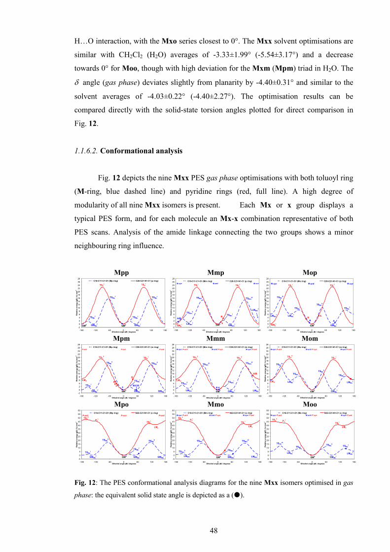
48
H…O interaction, with the Mxo series closest to 0°. The Mxx solvent optimisations are
similar with CH2Cl2 (H2O) averages of -3.33±1.99° (-5.54±3.17°) and a decrease
towards 0° for Moo, though with high deviation for the Mxm (Mpm) triad in H2O. The
δ angle (gas phase) deviates slightly from planarity by -4.40±0.31° and similar to the
solvent averages of -4.03±0.22° (-4.40±2.27°). The optimisation results can be
compared directly with the solid-state torsion angles plotted for direct comparison in
Fig. 12.
1.1.6.2. Conformational analysis
Fig. 12 depicts the nine Mxx PES gas phase optimisations with both toluoyl ring
(M-ring, blue dashed line) and pyridine rings (red, full line). A high degree of
modularity of all nine Mxx isomers is present. Each Mx or x group displays a
typical PES form, and for each molecule an Mx-x combination representative of both
PES scans. Analysis of the amide linkage connecting the two groups shows a minor
neighbouring ring influence.
Mpp
-2
0
2
4
6
8
10
12
14
16
18
20
22
24
26
28
-180 -120 -60 0 60 120 180Dihedral angle (θθθθ ) / degrees
Relative energy (
∆∆ ∆∆E) / kJ.m
ol-1
C16-C11-C1-O1 (Mp ring) C26-C21-N1-C1 (p ring)
TSMpI'
TSMpI
GM0
GM0' GMMp
I'GMMp
I
TSMpI
TSMpI'
TSpI
TSpI'
Mmp
-2
0
2
4
6
8
10
12
14
16
18
20
22
24
26
28
-180 -120 -60 0 60 120 180Dihedral angle (θθθθ ) / degrees
Relative energy (
∆∆ ∆∆E) / kJ.m
ol-1
C16-C11-C1-O1 (Mm ring) C26-C21-N1-C1 (p ring)
TSpI
TSMmIII'
TSMmII
GM0
GMpI
LMMmI'
TSpI'
LMMmI
TSMmIII
GMMmI
TSMmI
M-syn M-anti M-syn
B
A
A/B
Mop
-2
0
2
4
6
8
10
12
14
16
18
20
22
24
26
28
-180 -120 -60 0 60 120 180Dihedral angle (θθθθ ) / degrees
Relative energy (
∆∆ ∆∆E) / kJ.m
ol-1
C16-C11-C1-O1 (Mo ring) C26-C21-N1-C1 (p ring)
TSpI
TSMoIII
TSMoI
GM0GMp
I
LMMoI'
TSpI'
LMMoI
TSMoII
GMMoI
TSMoI'
M-syn M-anti M-syn
A
AB
B
Mpm
-2
0
2
4
6
8
10
12
14
16
18
20
22
24
26
28
-180 -120 -60 0 60 120 180Dihedral angle (θθθθ ) / degrees
Relative energy (
∆∆ ∆∆E) / kJ.m
ol-1
C16-C11-C1-O1 (Mp ring) C26-C21-N1-C1 (m ring)
TSmII
TSMpII
TSMpI
GM0
LMm
TSmI
TSMpII'
GMMpI
TSMpI'
GMMpI''
GMMpI'''
P-anti P-syn P-anti
B/C/D
B
A
A
DC
Mmm
-2
0
2
4
6
8
10
12
14
16
18
20
22
24
26
28
-180 -120 -60 0 60 120 180Dihedral angle (θθθθ ) / degrees
Relative energy (
∆∆ ∆∆E) / kJ.m
ol-1
C16-C11-C1-O1 (Mm ring) C26-C21-N1-C1 (m ring)
TSmII
TSMmIII
TSMmII
GM0
LMm
TSmII'
TSMmIII'
GMMmI'
TSMmI
LMMmI'
LMMmI
M-syn / P-anti M-anti / P-syn M-syn /P-anti
A
A/B
B
Mom
-2
0
2
4
6
8
10
12
14
16
18
20
22
24
26
28
-180 -120 -60 0 60 120 180Dihedral angle (θθθθ ) / degrees
Relative energy (
∆∆ ∆∆E) / kJ.m
ol-1
C16-C11-C1-O1 (Mo ring) C26-C21-N1-C1 (m ring)
TSmII
TSMoIII
TSMoII
GM0
LMm
TSmI
TSMoI
GMMoI
LMMoI
LMMoI'
TSMoI'
M-syn /P-anti M-anti / P-syn M-syn /P-anti
Mpo
-5
0
5
10
15
20
25
30
35
40
45
50
55
60
-180 -120 -60 0 60 120 180Dihedral angle (θθθθ ) / degrees
Relative energy (
∆∆ ∆∆E) / kJ.m
ol-1
C16-C11-C1-O1 (Mp ring) N22-C21-N1-C1 (o ring)
PoI
TSMpI'
TSMpII
GM0
LMo
TSoI
TSMpI
GMMpI'
TSMpII'
TSoII
GMMpI
GMMpI''
P-anti P-syn P-anti
Mmo
-5
0
5
10
15
20
25
30
35
40
45
50
55
60
-180 -120 -60 0 60 120 180Dihedral angle (θθθθ ) / degrees
Relative energy (
∆∆ ∆∆E) / kJ.m
ol-1
C16-C11-C1-O1 (Mm ring) N22-C21-N1-C1 (o ring)
PoI
TSMmI
TSMmIII
GM0
LMo
TSoI
TSMmII
LMMmI
TSMmIII'
TSoII
GMMmI LMMm
I'
M-syn /P-anti M-anti / P-syn M-syn / P-anti
Moo
-5
0
5
10
15
20
25
30
35
40
45
50
55
60
-180 -120 -60 0 60 120 180Dihedral angle (θθθθ ) / degrees
Relative energy (
∆∆ ∆∆E) / kJ.m
ol-1
C16-C11-C1-O1 (Mo ring) N22-C21-N1-C1 (o ring)
PoI
TSMoI
TSMoIII
GM0
LMo
TSoI
TSMoII
LMMoI
TSMoI'
TSoII
GMMoI
LMMoI'
M-syn /P-anti M-anti / P-syn M-syn / P-anti
Fig. 12: The PES conformational analysis diagrams for the nine Mxx isomers optimised in gas
phase: the equivalent solid state angle is depicted as a (�).

49
All optimised structures whether in the gas phase or in solvent have M-anti/P-
syn conformations (if applicable) as the most stable. However, in the Mmx triad, the
difference between the M-anti/P-syn and M-syn/P-syn conformations is as small as
0.84±0.05 kJ.mol-1 and implying a practical conformatial equivalence. The ab initio
results are summarized as follows:
Conformational analysis of the para-toluoyl (Mp) ring gives a PES profile with
two global maxima located ca. -60° and 120° (TSMpII[Mpm] = 15.48 kJ.mol-1 to
TSMpII[Mpo] = 17.22 kJ.mol-1), two local maxima ca. 25° and -155° (TSMp
I[Mpo] =
0.94 kJ.mol-1 to TSMpI[Mpp/m] = 1.73 kJ.mol-1). The four global minima are near 0°,
55°, ±180° and -130°.
Rotation of the meta-toluoyl (Mm) ring gives a PES profile with two global
minima ca. 55° and 0°, two global maxima at ca. -65° and 120° (TSMmIII[Mmm] =
14.07 kJ.mol-1 to TSMmIII[Mmo] = 16.20 kJ.mol-1), two local minima ca. -125° and
±180° with increases of (LMMmI[Mmo] = 0.79 kJ.mol-1 to LMMm
I[Mmm] = 0.89
kJ.mol-1). The two local maxima are at -155° and 25° (TSMmI[Mmo] = 1.18 kJ.mol-1 to
TSMmI[Mmp] = 3.20 kJ.mol-1).
Rotation of the ortho-toluoyl (Mo) ring gives a PES profile with one global
maximum at -135° (TSMoII[Moo] = 12.63 kJ.mol-1 to TSMo
II[Mop] = 14.99 kJ.mol-1),
one isolated local maxima at 45° (TSMoII[Moo] = 8.40 kJ.mol-1, TSMo
II[Mop/m] = 10.32
kJ.mol-1), two local maxima ca. -55° and 145° (TSMoII = 8.55±0.19 kJ.mol-1), two local
minima at ±180° and -90° (LMMoII[Moo] = 5.38 kJ.mol-1 to LMMo
II[Mop] = 6.06
kJ.mol-1) and two global minima at 0° and ca. 90°.
Rotation of the para-pyridyl (p) ring gives a PES profile with two global
maxima at ±90° (TSpI=22.75±0.08 kJ.mol-1) and two global minima at 0° and ±180°
whereas the meta-pyridine (m) ring has a PES profile with two global maxima ca. ±95°
(TSmI = 18.81±0.21 kJ.mol-1), two local minima at ±180° (LMm
I = 6.48±0.23 kJ.mol-1),
and one global minimum. Rotation of the ortho-pyridine (o) ring gives an asymmetrical
PES profile. One global maximum is located at -165° (TSoII[Moo] = 45.26 kJ.mol-1 to
TSoII[Mmo] = 47.39 kJ.mol-1), one local maxima at around 110° (TSo
I[Moo] = 40.69
kJ.mol-1 to TSoI[Mpo] = 42.32 kJ.mol-1), one local minimum at 135° (LMo
I[Moo] =
39.62 kJ.mol-1 up to LMoI[Mmo] = 40.77 kJ.mol-1) and of note, a plateau at -125°
(PoI[Moo] = 43.27 kJ.mol-1 up to Po
I[Mpo] = 45.34 kJ.mol-1).
The conformational analyses in the solvents CH2Cl2 and H2O (PCM-SMD
model)170 with comparisons between gas phase and solvents are depicted as PES scans
in Fig. 13.

50
Mpp
-2
0
2
4
6
8
10
12
14
16
18
20
22
24
26
28
-180 -120 -60 0 60 120 180Dihedral angle (θθθθ ) / degrees
Relative energy (
∆∆ ∆∆E) / kJ.m
ol-1
C16-C11-C1-O1 (Mp ring) C26-C21-N1-C1 (p ring)
Mmp
-2
0
2
4
6
8
10
12
14
16
18
20
22
24
26
28
-180 -120 -60 0 60 120 180Dihedral angle (θθθθ ) / degrees
Relative energy (
∆∆ ∆∆E) / kJ.m
ol-1
C16-C11-C1-O1 (Mm ring) C26-C21-N1-C1 (p ring)
Mop
-2
0
2
4
6
8
10
12
14
16
18
20
22
24
26
28
-180 -120 -60 0 60 120 180Dihedral angle (θθθθ ) / degrees
Relative energy (
∆∆ ∆∆E) / kJ.m
ol-1
C16-C11-C1-O1 (Mo ring) C26-C21-N1-C1 (p ring)
TSMoIII
TSMoII
Mpm
-2
0
2
4
6
8
10
12
14
16
18
20
22
24
26
28
-180 -120 -60 0 60 120 180Dihedral angle (θθθθ ) / degrees
Relative energy (
∆∆ ∆∆E) / kJ.m
ol-1
C16-C11-C1-O1 (Mp ring) C26-C21-N1-C1 (m ring)
Mmm
-2
0
2
4
6
8
10
12
14
16
18
20
22
24
26
28
-180 -120 -60 0 60 120 180Dihedral angle (θθθθ ) / degrees
Relative energy (
∆∆ ∆∆E) / kJ.m
ol-1
C16-C11-C1-O1 (Mm ring) C26-C21-N1-C1 (m ring)
Mom
-2
0
2
4
6
8
10
12
14
16
18
20
22
24
26
28
-180 -120 -60 0 60 120 180Dihedral angle (θθθθ ) / degrees
Relative energy (
∆∆ ∆∆E) / kJ.m
ol-1
C16-C11-C1-O1 (Mo ring) C26-C21-N1-C1 (m ring)
TSMoII
TSMoIII
Mpo
-5
0
5
10
15
20
25
30
35
40
45
50
55
60
-180 -120 -60 0 60 120 180Dihedral angle (θθθθ ) / degrees
Relative energy (
∆∆ ∆∆E) / kJ.m
ol-1
C16-C11-C1-O1 (Mp ring) N22-C21-N1-C1 (o ring)
TSMpII
TSMpII'
Mmo
-5
0
5
10
15
20
25
30
35
40
45
50
55
60
-180 -120 -60 0 60 120 180Dihedral angle (θθθθ ) / degrees
Relative energy (
∆∆ ∆∆E) / kJ.m
ol-1
C16-C11-C1-O1 (Mm ring) N22-C21-N1-C1 (o ring)
TSMmIII
TSMmIII'
Moo
-5
0
5
10
15
20
25
30
35
40
45
50
55
60
-180 -120 -60 0 60 120 180Dihedral angle (θθθθ ) / degrees
Relative energy (
∆∆ ∆∆E) / kJ.m
ol-1
C16-C11-C1-O1 (Mo ring) N22-C21-N1-C1 (o ring)
TSMoII
TSMoIII
Fig. 13: The PES conformational analysis diagrams for the nine Mxx isomers optimised in gas
phase (full line), CH2Cl2 (dashed line) and in H2O (dotted line) using the PCM-SMD solvation
method.
Comparisons between the gas-phase and solvated conformational analyses show
small differences: all Mxx isomers have the M-anti/P-syn conformations at the
stationary point regardless of the medium. Furthermore, the PES curve patterns are
similar, but there are differences in the rotational barrier heights where the solvent
dielectric constants influence significant changes (usually decreases, sometimes
increases) in the rotational energies necessary for aromatic ring flipping. Large
decreases in the rotational barriers in high dielectric solvents (methanol, DMSO) can
facilitate ring rotation and conformational changes. This can influence the ability to (a)
isolate more than one molecular conformation, (b) promote molecular disorder in the
solid state and (c) obtain more than one polymorph depending on solvent choice and
range.
Decreases of the rotational barriers for the p-/m-/o- rings are distinct and
consistent with the gas-phase. For p- the decrease is greater in H2O (~35%) than in
CH2Cl2 (~12%). A related decrease is noted in m- (~32% in CH2Cl2: ~ 65% in H2O)
and in the o-rings (~33% in CH2Cl2: ~60% in H2O).

51
The rotational barrier data for the Mx rings display different patterns than for the
p/m/o- rings and the nine Mxx isomers can be assigned to three groups. The 1st group
with Mpp, Mmp, Mpm and Mmm have small energy differences between the gas
phase and solvated forms suggesting minor or negligible influence of the solvents on
Mx ring rotation. The rotational barrier decreases in Mp are ~2% in CH2Cl2 and H2O,
but ~10% in CH2Cl2 and ~8% in H2O for Mm. The 2nd group comprising Mpo and
Mmo show negligible energy decreases over most of the curve but with a greater
decrease approaching TSMpII and TSMm
III. This decline of ~26% is similar in both Mp
and Mm rings regardless of the solvent. The 3rd group comprises the Mo ring (Mox)
triad having an unusual increase and shift of the rotational barrier TSMoII and TSMo
III. At
TSMoII the molecules are planar and the CH3 group is near the C=O group. On Mo ring
rotation from 0° the solvated state electronic energy remains high in CH2Cl2 from ~9%
(Mop) to ~23% (Moo); in H2O from ~20% (Mop) to ~46% (Moo) when compared with
the gas phase baseline curve, and to a minimum energy conformation. The higher
dielectric solvent destabilizes the planar molecular conformation. The remainder of the
curve shows a decrease by ~44% (CH2Cl2) and ~49% (H2O). A similar rotation energy
increase when the Mx ring is planar or rotating from 0° is seen in Mp and ~25% in
CH2Cl2 and ~19% (H2O), and in Mm, just for Mmo (~37% in CH2Cl2 and ~32% in
H2O). Overall, conformations are similar in all three media though with smaller
rotational energy barriers for the solvated forms and the more polar solvent H2O.
1.1.6.3. Energy results
The energy calculation results (CBS-QB3) (Table 10) comprise the electronic
energies (δESCF) and Gibbs free energies (δG) in all three media, including ∆Gsolv (for
CH2Cl2 and H2O) and ∆∆Gsolv (CH2Cl2 vs. H2O). The differences among each molecule
are presented as δESCF (δG) and the differences between media as ∆ESCF (∆G). The
Mom energies were used as reference points for the gas phase and solvents. Detailed
results including absolute values for ESCF and G; zero point energies and thermal
energies are provided in the ESI I (Section 3.1.1).
The electronic energy results (gas phase) show that the Mxo series is the most
stable, with Mxm the least stable triad: Mmo is the most stable and Mom the least
stable of the Mxx isomers. The results demonstrate that an ortho-N atom has a
stabilising effect with an ortho-methyl having a slight destabilising effect.

52
Table 10: The energy calculation results for Mxx in kJ.mol-1
gas phase CH2Cl2 H2O gas phase→
CH2Cl2 gas phase→
H2O
H2O → CH2Cl2
δESCF δG δESCF δG δESCF δG ∆ESCF ∆Gsolv ∆ESCF ∆Gsolv ∆∆ESCF ∆∆Gsolv Mpp -22.31 -11.35 -27.34 -11.96 -26.62 -12.64 -74.73 -63.36 -58.06 -45.15 -16.67 -18.21Mmp -20.70 -11.34 -24.62 -13.26 -24.53 -10.24 -73.62 -64.67 -57.59 -42.76 -16.03 -21.91Mop -11.48 -3.89 -14.34 -6.46 -14.16 -6.82 -72.55 -65.31 -56.43 -46.79 -16.12 -18.53Mpm -10.85 -7.46 -12.88 -5.81 -12.18 -6.94 -71.73 -61.09 -55.09 -43.33 -16.64 -17.76Mmm -9.29 -7.45 -10.29 -7.40 -10.35 -4.12 -70.70 -62.69 -54.82 -40.52 -15.88 -22.17Mom 0.00 0.00 0.00 0.00 0.00 0.00 -69.70 -62.75 -53.75 -43.86 -15.94 -18.89Mpo -45.89 -33.60 -44.15 -29.52 -35.82 -22.87 -67.96 -58.67 -43.69 -33.12 -24.27 -25.55Mmo -44.16 -33.38 -41.73 -29.61 -33.39 -21.61 -67.26 -58.98 -42.98 -32.09 -24.28 -26.89Moo -34.32 -24.74 -30.75 -23.03 -22.99 -14.73 -66.13 -61.03 -42.42 -33.84 -23.70 -27.19
a Only the differences between each molecule (δ) and media (∆, ∆∆) are shown, Mom is the
reference molecule for the gas phase (ESCF = -683.2650 Eh, G = -686.2042 Eh) and for solvents
(CH2Cl2: ESCF = -683.2915 Eh, G = -686.2281 Eh; H2O: ESCF = -683.2855 Eh, G = -686.2209
Eh). Full data including zero-point energies (E0) and thermal energies (E) are provided in the
Appendix III.
Calculations using the CBS-QB3 compound method with PCM-SMD solvation
model provided theoretical values of ∆Gsolv in CH2Cl2 (and H2O), including theoretical
logKD/W (in the ESI I, section 3.1.1.4). These results are consistent with our
experimental observations and with no unexpected values. All compounds should be
103-104 times more soluble in CH2Cl2 as compared to H2O, while the Mxo series are
expected to be the least soluble in water.
1.1.7. Comparisons of the solid state and modelling data
The molecular conformations of the Mxx series from X-ray diffraction data and
ab initio calculations (gas phase and solvated) share similarities but exhibit distinct
differences especially in a subset of cases. In each PES diagram, the corresponding
torsion angles from the crystal structures data are incorporated as (�) and for Mmp,
Mop, Mpm and Mmm two or more (�) are depicted where more than one independent
molecule is present in the asymmetric unit (Z’ > 1).
For five of the nine Mxx isomers the torsion angle data derived from ab initio
calculations are reasonably consistent with the crystallographic geometric data and the
global minima (GM) similar and within 10-15° (Fig. 12). However, for Mmp, Mmm,
Mom and Moo, the crystallographic torsion angles differ from their respective ab initio
results and are not located in an energetically favourable conformation and based on our
ab initio results. Three solid-state conformations Mmp, Mmm and Mom adopt meta-

53
stable conformations (relative to calculations using the gas-phase energy baseline)
whereas Moo adopts an unstable conformation. However, in the solid-state the
conformations adopted by the Mxx isomers are more than compensated for by strong
intermolecular hydrogen bonds and packing forces driving the molecular packing and
structure aggregation in the crystal. The PES scans (CH2Cl2, H2O) (Fig. 13) indicate that
more polar solvents can facilitate aromatic ring rotations and may predispose Mxx
isomers crystallising from such solvents to adopt unexpected conformations. The ability
of a more polar solvent (usually through hydrogen bonding) to interact with the solute
may provide an indication of a possible tendency towards polymorphism (or at least to
steer towards this possibility).
The optimised Mmx triad shows a trend with their tolyl rings in an M-anti
conformation (in close proximity to the C=O group), whereas the Mmp crystal structure
is M-syn with the tolyl ring rotated by -170° from the optimized Mmp conformation
(A/B in Fig. 12). Patterns also emerge in the optimised Mxm triad with the pyridyl rings
in the P-syn conformation (on the amide N-H side), whereas in the Mmm and Mom
(LMm in Fig. 12) crystal structures the P-anti conformation is observed and presumably
due to aggregation events. Crystals of Mom (M-anti/P-anti) proved elusive and only
obtained after many attempts and from ethyl acetate. The CBS-QB3 calculations
indicate Mom as the least stable isomer and PES scans show several possible
conformations and geometries, four for the Mo and two for the m (meta-pyridyl) ring
within 10-15 kJ.mol-1 which can easily be achieved in solution and may influence the
crystallisation event and our inability to easily crystallize Mom.
In Moo the tolyl ring dihedral angle is suggestive of an energetically
unfavourable conformation as M-syn/P-syn (Fig. 12, TSMoI). The stability of Moo as a
dimer in the solid-state {via N-H···N and two short C-H···π(arene) interactions}
highlights the dimerisation driven by cyclic R2
2(8) ring formation and this more than
compensates for twisting of the tolyl torsion angle in the crystal structure of Moo. The
observation of the Mxo isomers as the most stable triad may be due to delocalised
system N22-C21-N1-C1=O1; the ortho-pyridine ring conformation with one deep
energy minimum at GM0 illustrates this stability.

54
1.2. Fxx isomer grid
1.2.1. General description of synthesis
All nine Fxx compounds were synthesised using standard nucleophilic acyl
substitution reaction (Schotten-Baumann reaction, Scheme 24) between 4-/3-/2-
aminopyridines and 4-/3-/2-fluorobenzoyl chlorides. In general, the procedure was as
described for Fxp compounds in our previous publication.162 However, a different
procedure was applied to the Fxo compounds. The Fxm compounds were prepared by
the condensation reaction of 3-aminopyridine (3-AP) with 4-/3-/2-fluorobenzoyl
chlorides in CH2Cl2 in the presence of one equivalent of Et3N.
In 100 ml round bottom flask 3-aminopyridine (0.6219 g, 6.6 mmol) was
dissolved with stirring in 50 ml of CH2Cl2 and Et3N (1.394 ml, 10 mmol) was added.
The flask with reaction mixture was placed on an ice bath and allowed to cool. Under an
inert atmosphere of N2, 4-/3-/2-fluorobenzoyl chlorides (6.6 mmol) were added and the
reaction mixture stirred overnight. The reaction mixture was washed three times with an
aqueous KHCO3 solution and the organic layer was dried with anhydrous MgSO4. The
solvent was evaporated and the product left for crystallization. A crystalline product
was purified with column chromatography with silica as stationary phase and a mixture
of CHCl3, ethyl acetate and acetone (2:2:1).
Table 11: Product quantities, yields and melting points of Fxx compounds
Fxx m/g yield/% m.p./ºC Fpp 1.160 81.3 186.1-187.8 Fmp 1.133 79.4 185.0-186.6 Fop 3.711 86.7 134.7-135.6 Fpm 1.097 76.9 148.8-149.1 Fmm 1.046 73.3 149.7-152.2 Fom 1.926 67.5 89.2-89.6 Fpo 0.771 54.0 117.2-123.1 Fmo 1.275 59.0 76.7-77.4 Foo 1.567 36.2 84.0-86.1
Since 2-aminopyridine has increased reactivity due to the ortho nitrogen and
readily undergoes dibenzoylation reaction giving imides160-162 syntheses of Fxo was
based on nucleophilic acyl substitution reaction between 2-AP and fluorobenzoyl
chlorides, employing pyridine as reaction medium and without catalytic base, at -10ºC.
The detailed procedure was as follows.
The 2-aminopyridine (0.9412 g, 10 mmol) were added to a 100 ml two-neck
round bottom flask placed on an ice bath (ice/water/NaCl/NH4Cl) with stirring. Then,

55
30 ml of solvent (pyridine) was added. The flask was placed on ice bath and reaction
mixture was allowed to cool to -10ºC. Finally, the 4-/3-/2-fluorobenzoyl chloride (5
mmol) were added slowly into the solution mixture. The reaction mixture was allowed
to warm to room temperature and stirred overnight. Into the reaction mixture 100 ml of
purified water was poured and conc. HCl was gradually added until pH = 5-6. A white
precipitate formed, and filtered on a Buchner's funnel. The precipitate was washed with
copious amounts of water and allowed to dry. The pale yellow products were purified
with column chromatography (Fpo and Fmo: silica// CHCl3/ethyl acetate/n-hexane =
4:2:1, Foo: CHCl3/ethyl acetate/n-hexane = 4:5:1).
N
NH2
N
NH2
N
NH2
NH
NO
NH
N
O
NH
N
O
N N
O
O
F
F
F
F F
p/m/o-FC6H4COCl
Et3N, CH2Cl2
p/m/o-FC6H4COCl
Et3N, CH2Cl2
p/m/o-FC6H4COCl
pyridine
2-Aminopyridine (2-AP)
3-Aminopyridine (3-AP)
4-Aminopyridine (4-AP) Fxp
Fxm
Fxo
Fxod
Scheme 24: Schematic diagram of the Fxx reactions
1.2.2. X-ray crystallography methods
Single crystals of the Fxx isomers including the three Fxp compounds162 were
obtained by slow evaporation at 4ºC or 21ºC and typically from ethyl acetate, while
Fmo was grown from CDCl3. The only Fxx isomer that proved difficult to crystallise as
diffraction quality crystals was Fom: decent quality crystals were obtained only after a
series of crystal growth experiments from mixtures of methanol and diethyl ether. The

56
X-ray data were collected on a Gemini S Ultra diffractometer at 294(1) K, with a θ
range from 2-25° minimum and 100% data coverage to 25° (on θ).176
Data reduction procedures and absorption corrections are standard and
comprehensive details have been published elsewhere.176 All structures were solved
using the SHELXS97 direct methods program3 and refined by full matrix least squares
calculations on F2 with all non-hydrogen atoms having anisotropic displacement
parameters. Hydrogen atoms were treated as riding atoms using the SHELXL97
defaults3 (at 294 K) except for the amide N-H (isotropic refinement) using the OSCAIL
software168 with selected crystallographic and structural information in the ESI I,
Section 2.2. Molecular and hydrogen bonding diagrams (Figs. 15-22) were generated
using PLATON.169 All searches on the Cambridge Structural Database (CSD) were
performed with the November 2010 release (version 5.32+4 updates).8
1.2.3. Computational methods
The computational methods and procedures reported herein are similar to
previous isomer grid (Mxx) using Gaussian03/09.25 The ab initio DFT (B3LYP)
geometry optimisations in gas phase were performed with and without polarisation
functions (as 6-311++G, 6-311G**, 6-311++G**) in order to probe the influence of
polarisation functions on the overall structure and conformation. The B3LYP/6-
311++G** basis set is close to optimal for the Fxx isomer series in terms of both
accuracy of geometry and computational costs. As polarisation functions are important
in molecular geometry optimisation and especially when hydrogen bonds are involved,
we rigorously examined the influence of both diffuse and polarisation functions on key
structural parameters by gas phase optimisation of the Fxx isomers using three distinct
basis sets (as above). Solvated geometry optimisations and conformational analyses
were performed in two solvents, CH2Cl2 and H2O (PCM-SMD solvation model)170
specifically using the B3LYP/6-311++G** basis set. Additionally, high accuracy energy
calculations including ∆Gsolv were obtained using the CBS-QB3 compound method.171
The conformational analysis of each Fxx structure was undertaken using PES
scans of the two key dihedral angles over ±180º both in gas phase and solvents: the
angles used are C12-C11-C1=O1 (α, F-ring), and C1-N1-C21-C26 (β, P-ring). Each
asymmetric (meta or ortho) ring, can adopt, relative to the amide linker, two
conformations (syn or anti) (Scheme 25). Therefore, the fluorophenyl (F-ring) or
pyridine (P-ring) rings can be either in the syn (F-syn, P-syn) or anti (F-anti, P-anti)

57
conformation. Rings with para-pyridine N or para-phenyl F atoms are not subject to
this convention. The results provide PES diagrams highlighting conformation
preferences (syn/anti) and rotational barriers in kJ.mol-1.
The computational analyses were performed to (i) investigate the effect of the
polarisation functions (** or d,p) with the B3LYP/6-311++G basis set on molecular
geometry and conformation, (ii) facilitate comparisons of the optimised structures and
conformations with the solid state structural results and (iii) examine the influence of
the solvation model (CH2Cl2, H2O; PCM-SMD method) on the Fxx molecular geometry
and conformations.
NH
O
YZ
ZY
F
F
P-syn
F-syn
P-anti
F-anti
Scheme 25: The four possible Fxx conformations 1.2.4. Comment on synthesis and general characteristics
The Fxx compounds (as expected for benzamides) are crystalline, colourless,
odourless solids, readily soluble in most organic solvents, less soluble in cyclohexane
and diethylether but insoluble in water. The yields (Table 11) were excellent for the
Fxp/Fxm isomers, but lower for Fxo due to the competing reaction (and strategies were
employed to prevent a significant formation of (2:1) imide products). The compound
purities, following standard purification and chromatography, were excellent as
analysed by TLC. In related benzamides we have noted similar trends with the melting
point ranges and median values dropping from the symmetrical Fpp to the less
symmetrical isomers, with Fmo having the lowest melting point. The melting points of
Fop and Fom are ~50ºC lower than the related isomers in the Mxx series (Section 1.1).
1.2.5. Comment on spectroscopic data
All spectroscopic data, including 1H, 13C and 19F NMR, as well as IR spectra are
listed in the Appendix I (Section 1.2), while the spectra are presented in the ESI I,

58
Section 1.2. There is a high degree of modularity within the P- and F-rings as noted
previously in Mxx.
The amide proton (δN-H) resonance at ca. 8.37 ppm (CDCl3) shifts to 10.62 ppm
(DMSO-d6) in the six Fxp/Fxm isomers. However, the average δN-H for Fxo is ca. 8.94
ppm (CDCl3) and shifted to ~10.85 ppm in DMSO-d6. The smaller difference for the δN-
H in Fxo (CDCl3) as compared to Fxp/Fxm results from the higher acidity of the amide
proton and influenced by the ortho-pyridine N atom. The most distinct feature in the
Fxx NMR spectra is the splitting of the N-H peak into a broad doublet in the Fox triad
(Fop, Fom, Foo) when using aprotic solvents such as CDCl3 (ESI I, Section 1.2).162
This splitting results from the strong through-space nuclear spin–spin couplings (1hJN–
H...F = 13-15.5 Hz), caused by the formation of a strong N-H···F interaction between the
ortho-F atom and amide proton.177 The N-H peak is present as a broad singlet in polar
solvents (DMSO-d6, ESI I, Section 1.2) suggesting that the intramolecular N-H···F
hydrogen bonding is disrupted with resulting conformational change. Our detailed
studies of conformational analyses using both gas phase and solvated models for the
Mxx analogues suggests that the use of highly polar solvents (high dielectric constants)
decreases the rotational barriers so as to facilitate ring rotation and conformational
changes. This is what is observed when the N-H···Fortho interaction is disrupted in the
Fox triad in polar solvents such as DMSO. The IR spectra for Fxo triad are similar with
typical strong and diffused stretching bands between 3333 and 2700 cm-1 with
prominent peaks distinctly present at 3078, 3175 and 3112 cm-1.
1.2.6. Crystallographic data and analysis
1.2.6.1. General comments
The salient features of the Fxx structures are provided in Tables 12 and 13; all
other important crystallographic details are included in the ESI II (Section 2.2). The 3 ×
3 isomer grid of nine Fxx compounds is augmented by two pairs of polymorphs for
Fpm and Fom. For Fpm, one polymorph as Fpm_O exhibits N-H···C=O
intermolecular interactions as amide···amide C(4) chains, while Fpm_N aggregates by
the amideN-H···Npyridine interactions (both in space group P21/n, Z' = 1). In Fom, both
polymorphs Fom_O and Fom_F exhibit N-H···O=C intermolecular hydrogen bonding
but in different space groups, with different conformations and disorder (Fom_O). For
the remaining isomers, Fmm aggregates via N-H···N interactions while all Fxo isomers
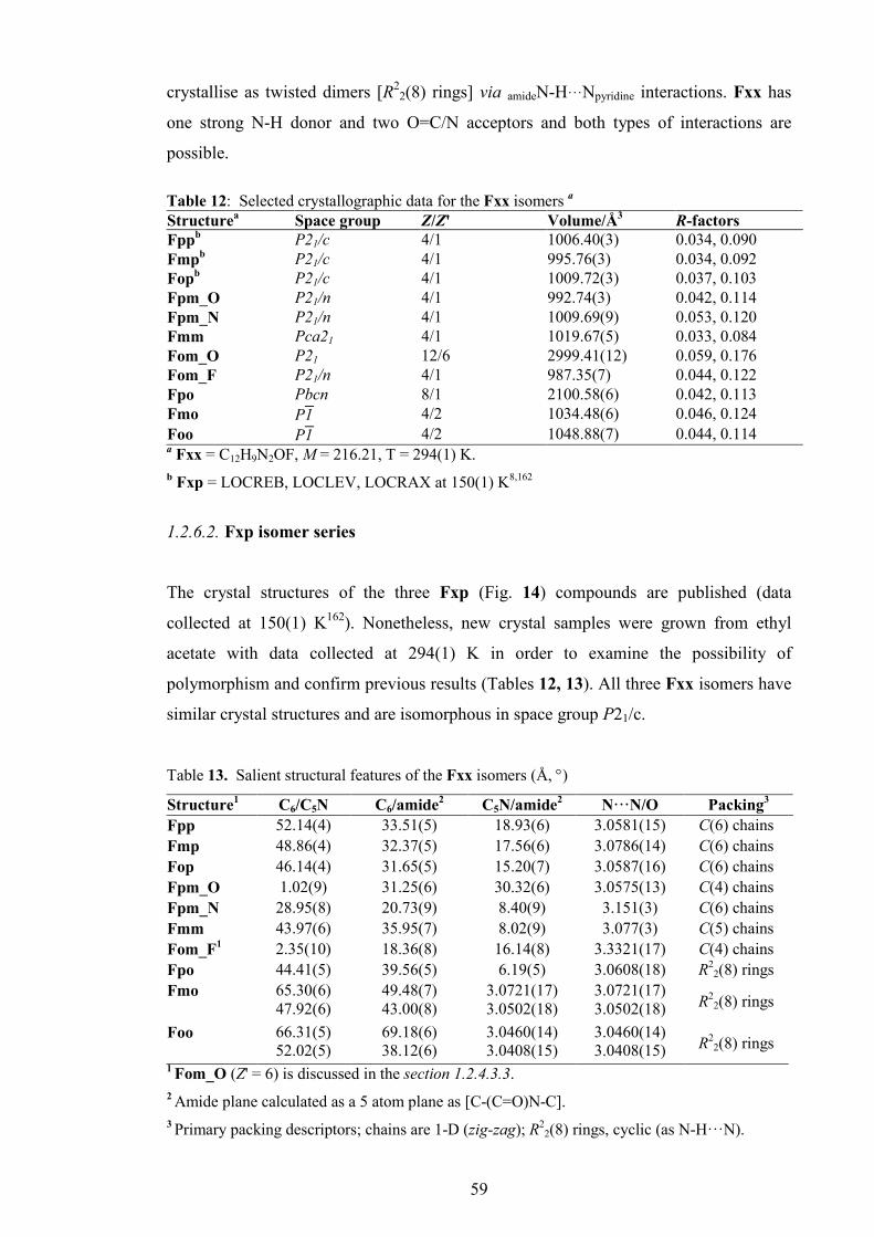
59
crystallise as twisted dimers [R22(8) rings] via amideN-H···Npyridine interactions. Fxx has
one strong N-H donor and two O=C/N acceptors and both types of interactions are
possible.
Table 12: Selected crystallographic data for the Fxx isomers a
Structurea Space group Z/Z' Volume/Å3 R-factors
Fppb P21/c 4/1 1006.40(3) 0.034, 0.090 Fmpb P21/c 4/1 995.76(3) 0.034, 0.092 Fopb P21/c 4/1 1009.72(3) 0.037, 0.103 Fpm_O P21/n 4/1 992.74(3) 0.042, 0.114 Fpm_N P21/n 4/1 1009.69(9) 0.053, 0.120 Fmm Pca21 4/1 1019.67(5) 0.033, 0.084 Fom_O P21 12/6 2999.41(12) 0.059, 0.176 Fom_F P21/n 4/1 987.35(7) 0.044, 0.122 Fpo Pbcn 8/1 2100.58(6) 0.042, 0.113 Fmo P̅1 4/2 1034.48(6) 0.046, 0.124 Foo P̅1 4/2 1048.88(7) 0.044, 0.114 a Fxx = C12H9N2OF, M = 216.21, T = 294(1) K. b Fxp = LOCREB, LOCLEV, LOCRAX at 150(1) K8,162
1.2.6.2. Fxp isomer series
The crystal structures of the three Fxp (Fig. 14) compounds are published (data
collected at 150(1) K162). Nonetheless, new crystal samples were grown from ethyl
acetate with data collected at 294(1) K in order to examine the possibility of
polymorphism and confirm previous results (Tables 12, 13). All three Fxx isomers have
similar crystal structures and are isomorphous in space group P21/c.
Table 13. Salient structural features of the Fxx isomers (Å, °)
Structure1 C6/C5N C6/amide2 C5N/amide2 N···N/O Packing3
Fpp 52.14(4) 33.51(5) 18.93(6) 3.0581(15) C(6) chains Fmp 48.86(4) 32.37(5) 17.56(6) 3.0786(14) C(6) chains Fop 46.14(4) 31.65(5) 15.20(7) 3.0587(16) C(6) chains Fpm_O 1.02(9) 31.25(6) 30.32(6) 3.0575(13) C(4) chains Fpm_N 28.95(8) 20.73(9) 8.40(9) 3.151(3) C(6) chains Fmm 43.97(6) 35.95(7) 8.02(9) 3.077(3) C(5) chains Fom_F1 2.35(10) 18.36(8) 16.14(8) 3.3321(17) C(4) chains Fpo 44.41(5) 39.56(5) 6.19(5) 3.0608(18) R
22(8) rings
Fmo 65.30(6) 47.92(6)
49.48(7) 43.00(8)
3.0721(17) 3.0502(18)
3.0721(17) 3.0502(18) R
22(8) rings
Foo 66.31(5) 52.02(5)
69.18(6) 38.12(6)
3.0460(14) 3.0408(15)
3.0460(14) 3.0408(15) R
22(8) rings
1 Fom_O (Z' = 6) is discussed in the section 1.2.4.3.3. 2 Amide plane calculated as a 5 atom plane as [C-(C=O)N-C]. 3 Primary packing descriptors; chains are 1-D (zig-zag); R2
2(8) rings, cyclic (as N-H···N).

60
Bond lengths and angles are normal and the difference in C-F bond lengths noted
previously is evident with 1.3591(14) Å (Fpp), 1.3517(16) Å (Fmp) and 1.3420(15) Å
(Fop), presumably arising from the influence of the secondary interactions/contacts and
intramolecular N1-H1···F12 in (Fop).
Of note is the expanding list of structures isomorphous with the Fxp triad (Table
5)172 including the parent N-(4-pyridyl)benzamide [MOHQOP]178 and 2,5-difluoro-(4-
pyridyl)benzamide [HOFVUU].172 This series of five compounds is unusual in that the
compounds are isomorphous (with similar unit cell parameters, packing and alignment)
but differ in their F/H peripheral atom-site position and interactions/contacts at the
secondary level. This arises principally due to the ca. 0.4 Å difference between typical
organic C-F/C-H bond lengths and the resulting directional influence on weaker
interactions and contacts. The Fxp details are not discussed further except for
comparisons (Tables 12, 13).
1.2.6.3. Fxm isomer series
Fpm polymorphs molecular and crystal structures
The Fpm isomer was isolated as two polymorphs Fpm_O and Fpm_N (suffix
O/N based on the primary hydrogen bonding interactions), both of which crystallise in
space group P21/n with Z' = 1.179,180 The IR spectra of both polymorphs show prominent
differences in the N-H stretching region (2800-3400 cm-1) with Fpm_O showing a
sharp peak at 3325 cm-1 and characteristic for all amide···amide (N-H···O=C) hydrogen
bonded benzamides/pyridinecarboxamides, while Fpm_N has a diffuse pattern of N-H
stretching bands indicative of N-H···N bonded benzamides/pyridinecarboxamides.
Fig. 14: An overlay of the Fxp isomorphous series with 25_F2

61
The IR spectrum of the bulk Fpm powder shows a diffuse peak pattern
suggesting a prevalence of the Fpm_N polymorph. This polymorph seems to be
preferred as the Fpm_O polymorph was isolated by chance. Crystals of the Fpm_O
polymorph grow from CH2Cl2 have N-H···O=C primary hydrogen bonding as C(4)
chains, while Fpm_N (from ethyl acetate) has intermolecular N-H···N interactions. It is
rather unusual (though not unknown) that both polymorphs crystallise in the same space
group and differing primarily in their main hydrogen bonding interactions.181
Figs. 15, 16: Views of Fpm_O and Fpm_N
The Fxx series with a strong N-H donor and two O=C/pyridine N acceptors
offers the possibility of obtaining at least two different structures with either or both N-
H···N/N-H···O=C interactions though in practice one type is clearly favoured for a
particular Fxx isomer. In Fpm_O the N-H···O=C interaction (N1···O1i = 3.0575(13) Å;
i = x,y+1,z) links Fpm molecules into 1-D chains along the b-axis direction and parallel
to the (101) plane. The remaining interactions are weak with 1-D chains (running anti-
parallel) linked by C15-H15···N23 (C15···N23ii = 3.5891(17) Å, ii = 1-x,1-y,-z) contacts
into columns, with additional C14-F14···F14-C14iii = 2.8982(18) Å, iii = 2-x,-y,-z)
contacts. The pyridine P-ring conformation in Fpm_O is P-syn and the two aromatic
rings are almost parallel though with the amide group twisted away from both rings
(Table 13). The Fmp_O molecular geometry (torsion angles) differs considerably from
Fmp_N (Table 13). However, the most significant bond length/angle difference is for
C1-N1-C21 = 125.76(10)° in Fpm_O and 127.7(2)° in Fpm_N.
Aggregation in Fpm_N is principally by N1-H1···N23 interactions (N1···N23i =
3.151(3) Å, i = -1/2+x,1/2-y,1/2+z) forming 1-D zig-zag chains along the c-axis
direction and parallel to the (-101) plane. This primary N-H···N interaction is
augmented by flanking C16-H16···N23i and C26-H26···N23i interactions {with
C16/C26···N23i = 3.403(3)/3.390(3) Å} and similar to the NmpF and NmpM structures
(Sections 2.1 and 2.2). The 1-D chains are linked into 2-D sheets by weak C-H···F

62
interactions (H24···F14ii = 2.57 Å, C24···F14ii = 3.107(3) Å, ii = 3/2-x,-1/2+y,1/2-z)
along the [010] direction. There are no other direction specific interactions in Fpm_N.
The most striking difference between Fmp_N and Fmp_O is the P-anti
conformation which is opposite to the P-syn in Fmp_O. This conformation change in
the pyridine ring orientation is essential for intermolecular N-H···N hydrogen bonding
in Fmp_N. The Fpm_O structure resembles the related methyl isomer derivative Mpm
(Section 1.1). However, and in contrast to Fpm_O, the Mpm isomer crystallises in
space group P1 with Z' = 4 and contains four distinct hydrogen bonded chains
aggregating via N-H···O=C interactions.
Fig. 17: Aggregation in Fpm_N
Fmm molecular and crystal structure
The Fmm isomer shows some similarities with Fpm_N in terms of aggregation
and conformation. As in Fmp_N, the conformation of Fmm is F-anti/P-anti and as
noted above the P-anti conformation is crucial for formation of the amideN-H···Npyridine
hydrogen bond. The principal interaction in Fmm is N1-H1···N23i (N1···N23i =
3.077(3) Å, i = x+1/2,1-y,z) and augmented by a flanking C26-H26···N23i (C26···N23 =
3.444(3) Å) interaction linking Fmm molecules into 1-D chains along the a-axis (100)
direction. A secondary interaction involves π···π stacking (C26···C22ii = 3.366(3) Å, ii
= -1/2+x,1-y,z) along the c-axis direction weakly connecting the 1-D chains into 2-D
sheets parallel to (010) plane. There are no other interactions in Fmm.

63
Fom polymorphs molecular and crystal structure
The Fom isomer was isolated as two polymorphs with Fom_O grown as poor
quality single crystals from ethyl acetate (amongst other solvents and mixtures) after
many attempts. A second polymorph, Fom_F crystallised subsequently as fine
diffraction quality single crystals by very slow evaporation from MeOH in long tubes.
The Fom_O polymorph crystallises in space group P21 (Z' = 6). The structure solves
easily in P21 using default settings in common structure solution programs and even at
this juncture it is obvious that there is considerable disorder in Fom_O. On refinement
the Fom_O structure is revealed to be completely disordered with the six individual
molecules having varying levels of disorder, from four molecules with a minor
component (~10%) and two having complete 50% molecular disorder.
Figs. 18, 19: Views of Fmm and Fom_F
All six Fom_O molecules are F-syn as this facilitates the favourable
intramolecular N-H···Fortho interaction as noted in the 1H NMR of related benzamides.177
The N···F distances for (A) to (D) range from 2.722(5) to 2.753(6) Å. The meta-
pyridine ring is mostly P-syn with evidence for the P-anti conformation in at least one
of the 50:50 disordered molecules (F/H). The possibility of a second conformation of
the pyridine ring in the crystal structure may be needed to effect a repeat unit on
crystallisation but at the cost of a crystal structure with Z' = 6.
The primary interaction consists of six distinct N-H···O=C C(4) chains of all six
molecules in the b-axis direction. The intermolecular N···O distances range from
3.066(8) Å to 3.111(9) Å and C6/C5N interplanar angles range from 4.5(4)° to 9.1(4)°
for (A) to (D). The four largely ordered molecules (A) to (D) stack in a column along
the a-axis direction with the remaining two molecules as 50:50 disordered components
(E/G) and (F/H) stacking as a column in the (100) direction adjacent to (A) to (D).

64
Alternating columns of (A) to (D) and (E/G), (F/H) are linked by weak
interactions/contacts. The assembly of the structure is perplexing and our analysis
suggests that the ortho-F atom plays a major role in the molecular conformation. The
Fom_O crystal structure as a completely disordered system can be viewed as the kinetic
product of imperfect crystallisation. Fom_O is worthy of a more detailed study over a
range of temperatures.
A review of the CSD8 for structures with Z' = 6 in space group P21 reveals 42
compounds of which bis[4-(dimethylamino)phenyl]diazene oxide [XIYZOV]182 is a
representative planar molecule. It is described as a commensurate modulation of a P21/c
parent with ⅓ of the b-axis, and comprising two disordered molecules with an
indication of disordered components in two of the remaining azoxybenzene molecules
The Fom_F polymorph crystallises in P21/n and is isostructural with Fpm_O
and has similar geometry features, but the conformation as (F-syn/P-anti) is similar to
Fpm_N. The primary Fom_F interaction is the long N-H···O=C hydrogen bond
(N1···O1i = 3.3322(17) Å, i = x+1,y,z) as C(4) chains linking molecules into 1-D chains
along a-axis. Apart from the intramolecular N-H···Fortho interaction, the N-H···O=C is
the only intermolecular interaction of consequence in Fom_F apart from the repulsive
C16-H16···H16-C16ii interaction (H16···H16ii = 2.33 Å) and a weak C14-H14···N23iii
interaction linking chains (ii = -1-x,1-y,-z; iii = 1/2+x,1/2-y,1/2+z). Examination of both
structures allows us to understand the difficulty Fom has in forming quality crystals.
1.2.6.4. Fxo isomer series The Fxo triad form twisted dimers as R2
2(8) rings via cyclic amideN-H···Npyridine
interactions denoted by (N-H···N)2. Formation of dimers with the pyridine N atom
located ortho (a mandatory P-syn conformation) has already been discussed in the
related Mxo isomers (Section 1.1). In these Mxo isomers the central hydrogen bonded
R2
2(8) ring is essentially planar while the Fxo dimers as twisted dimers have interplanar
C5N/C5N or [NCNH/NCNH] angles of 39.12(4)º, [34.63(15)º] in Fpo, 43.66(7)º,
[30.9(16)º] in Fmo, and 22.18(5)º, [21.6(6)º] in Foo. In the Fxo triad (on dimer
formation) the N-H and pyridine N are excluded from further intermolecular
interactions and the three crystal structures rely on weaker C-H···O/F/π or π···π
secondary interactions.

65
Fpo molecular and crystal structure
Fpo (Fig. 20) crystallises as a hydrogen bonded R22(8) dimer via N1-H1···N22
interactions (N1···N22i = 3.0608(18) Å, i = -x,y,1/2-z) but in tandem with a C16···C23i
= 3.285(2) Å contact. Pairs of dimers are connected into tetramers by C16-H16···O1
interactions (C16···O1ii = 3.266(2) Å, ii = x,1-y,1/2+z) and enhanced by a C15-
H15···C12 contact. Tetramers are linked into a 1-D column by C25-H25···O1iii (iii = -
x,y,3/2-z) interactions along the c-axis direction. The weak C12-H12···F14iv (iv =
1/2+x,-1/2+y,1/2-z) interaction alternatively interconnects 1-D columns into a 3-D
structure.
Fig. 20: A view of the Fpo hydrogen bonded dimer
Fmo molecular and crystal structure
Fmo (Fig. 21) forms a twisted dimer through two distinct N1-H1···N22
interactions [N1A···N22B = 3.0721(17) Å and N1B···N22A = 3.0502(18) Å] as the two
Fmo molecules (A/B) are not identical (Z' = 2). Therefore all three major torsion angles
differ as well as the C6/C5N interplanar angles (Table 13).
Dimer formation also occurs with additional C16A/B···C23B/A contacts [both
contacts = 3.237(2) Å]. Dimers are linked into tetramers by two weak C-H···O contacts
(C16A-H16A···O1Bii, C15B-H15B···O1Aiii; ii = 1-x,1-y,1-z, iii = 1-x,2-y,1-z).
Tetramers are interconnected into a 1-D column by stronger C25A-H25A···O1B
[C25A···O1Bi = 3.235(2) Å, i = x,1+y,z] interactions in the b-axis direction. Columns
are further linked into a 2-D sheet parallel to the [10-1] plane by double π···π stacking

66
(C13A···C15Aiv, iv = -x,1-y,-z) and C14B···C14Bv (v = 2-x,2-y,2-z) contacts. It is
unusual that the fluorine atoms F13A/B (F-anti) do not play a significant role in the
Fmo crystal structure apart from influencing π···π stacking interactions.
Fig. 21: A view of the Fmo hydrogen bonded dimer
Foo molecular and crystal structure
The Foo crystal structure (Fig. 22) assembles in a similar fashion to Fmo at the
primary level (with Z' = 2). The interplanar angle between the two pyridinyl rings
C5NA/C5NB) is 22.18(5)º; the smallest among the Fxo dimers.
The Fo rings are oriented as F-syn allowing the formation of three contacts as
N1-H1B···F12B [N1B···F12B = 2.7981(15) Å] and C23-H23···π(C11,…,C16) with
H23A···Cg1B = 2.82 Å, C23A-H23A···Cg1B = 138°, while H23B···Cg1A = 2.70 Å,
C23B-H23B···Cg1A = 149° and stabilising the dimeric unit. In Foo these C23-
H23A/B···π(arene)B/A interactions are similar though not as significant as the analogous
C-H···π(arene) interactions described in Moo (Section 1.1). Dimers aggregate into
tetramers by two π···π contacts with C21A···C24Bi = 3.257(2) Å, (i = -x,-y,2-z) and
C24B-H24B···π(C21A,…,C26A)i. These are interconnected along the b-axis into a 1-D
column by weak C-H···O contacts (H25B···O1Aii = 2.62 Å, ii = x,-1+y,z) and
(C26A···O1Aiii = 3.225(2) Å, iii = -x,1-y,2-z). Further aggregation is accomplished via
weak contacts. In Foo the Fo rings have interplanar angles of 69.56(5)º and as both are
F-syn the F12A···F12B atoms are separated by a distance of 4.7995(15) Å.

67
Fig. 22: A view of the Foo hydrogen bonded dimers.
1.2.7. Ab initio calculations
1.2.7.1. Structure optimisation results
The main geometric parameters of the Fxx isomers (optimised in the gas phase
with different basis sets), for torsion angles C12-C11-C1=O1 (α), C1-N1-C21-C26 (β)
and O1-C1-N1-C21 (δ) are presented in the Table 14. Torsion angles (α, β and δ) of the
gas phase and solvated forms (CH2Cl2, H2O) obtained with implicit solvation model
PCM-SMD and B3LYP/6-311++G** basis set are listed in Table 15.
In general when examining geometry, the relative and absolute benzamide
geometry should be differentiated depending on whether the (syn-/anti-) conformation
is neglected or endorsed. If the conformation is taken into account then the given
geometrical parameter values (torsion angles) are regarded as absolute geometry. In the
reverse case, if conformation is neglected then the relative values of the geometry are
provided, in order to give emphasise the relative molecular shape and for comparisons
with other isomers having different conformations.
For Fxx, the additional polarisation function (6-311++G**) does not yield a
significant change in the relative geometric parameters in gas phase as compared to the
standard (6-311++G) basis set (ESI I, Section 3.2.). The most significant change is for
the β and δ angles (Table 14). However, the polarisation function changes the preferred
conformation of the Fm ring making the F-anti slightly preferable to F-syn.
Alternatively the exclusion of diffuse functions (from the standard set but with added
polarisation functions as 6-311G**) slightly changes the α dihedral angle (F-ring).
Analysis of the Fxx isomers reveals the 6-311++G** basis set to be optimal in terms of

68
time and computational expense and does not significantly influence relative geometry
(apart from the Fm ring).
The most prominent feature of the modelled Fxx isomers is the planarity of the
Fox triad. Optimisation of the Fox isomers suggests the existence of intramolecular
hydrogen bonding between ortho-fluorine and amide group (as N-H···F) regardless of
the basis set. The N-H···F interaction (according to models) is responsible for the Fox
triad planarity. Optimisation (using the solvation model) shows that the Fox triad are
less planar in low polar solvents (CH2Cl2, CDCl3), while in highly polar solvents (H2O,
DMSO) the N-H···F interaction may distort from planarity (Fom/Foo: α = -7.14±0.73º;
β = -4.22±0.36º; δ = -0.26±0.60º).
Table 14: Torsion angles (°) of Fxx isomersa optimised with different basis sets 6-311++G** 6-311++G 6-311G** α β δ α β δ α β δ
Fpp -24.45 -5.33 -3.10 -25.75 -3.74 -4.69 -22.27 -4.24 -2.87Fmp -24.95 -4.70 -2.85 151.63 -3.69 -4.24 -23.52 -4.24 -2.37Fop -0.03 0.01 0.03 0.00 0.00 0.00 0.00 0.00 0.00Fpm -24.27 -5.67 -2.51 -25.54 -3.45 -4.30 -22.07 -4.14 -2.34Fmm -24.62 -4.79 -2.29 151.90 -3.68 -3.84 -23.20 -4.15 -1.84Fom 0.01 0.00 -0.02 -0.05 0.02 -0.02 0.02 0.01 -0.03Fpo -21.73 -3.44 -2.66 -22.36 -2.06 -3.86 -19.05 -3.68 -2.10Fmo -22.08 -2.96 -2.55 -21.95 -1.75 -3.68 -19.69 -3.34 -2.09Foo -0.01 0.00 0.00 -0.02 -0.02 0.04 -0.01 0.00 0.00a The angle C12-C11-C1=O1 (F-ring) is α; angle C1-N1-C21-C26 angle (P-ring) is β and O1-
C1-N1-C21 angle (amide linkage) is δ.
Table 15. Torsion angles (°) of optimised Fxx isomersa
optimised in gas phase optimised in CH2Cl2 optimised in H2O α β δ α β δ α β δ
Fpp -24.45 -5.33 -3.10 -25.49 -6.72 -3.14 -26.21 -12.01 -3.10
Fmp -24.95 -4.70 -2.85 -24.78 -4.47 -2.93 -24.43 -6.72 -3.40
Fop -0.03 0.01 0.03 0.01 0.00 0.00 -0.01 0.00 0.00
Fpm -24.27 -5.67 -2.51 -25.36 -7.76 -2.71 -25.52 -16.41 -2.10
Fmm -24.62 -4.79 -2.29 -24.62 -5.38 -2.43 -23.91 -12.62 -1.64
Fom 0.01 0.00 -0.02 -0.05 0.00 0.00 -6.62 -4.48 -0.68
Fpo -21.73 -3.44 -2.66 -25.54 -7.43 -2.10 -25.08 -6.11 -3.06
Fmo -22.08 -2.96 -2.55 -24.27 -3.76 -2.17 -24.16 -5.63 -3.66
Foo -0.01 0.00 0.00 -7.51 0.79 0.48 -7.65 -3.96 0.16a The angle C12-C11-C1=O1 (F-ring) is α; angle C1-N1-C21-C26 angle (P-ring) is β and O1-
C1-N1-C21 angle (amide linkage) is δ. All geometries are based on B3LYP/6-311++G**
optimisation with PCM-SMD solvation model.

69
The hypotheses (from calculations) are shown by 1H NMR (CDCl3; DMSO) that
the N-H···F interaction and Fox triad planarity exists in low polarity solvents but can be
disrupted in highly polar solvents.
The remaining Fpx/Fmx isomers optimised in gas phase have relatively
uniform geometries with the F-ring rotated (α = -23.68±1.40º), P-ring slightly rotated
(β = -4.48±1.06º) and planar amide dihedral angle (δ = -2.66±0.28º). The Fpx/Fmx
isomers optimised in CH2Cl2 agree (α = -25.01±0.52º; β = -5.92±1.64º; δ = -
2.58±0.42º) but in H2O the F-ring and amide dihedral angle are similar for gas phase
and CH2Cl2 (α = -24.88±0.88º, δ = -2.83±0.79º), however the P-ring differs. In Fpp,
Fpm and Fmm the P-ring exhibits increased rotation (β = -13.68±2.38º) while for Fmp,
Fpo and Fmo it is similar in CH2Cl2 (β = -6.15±0.55º). A similar increased rotation
under the influence of a high dielectric field was noted for Mxx (Section 1.1).
1.2.7.2. Conformational analysis
Fig. 23 shows nine PES diagrams for conformational analyses of the Fxx
isomers (in gas phase with 6-311++G** basis set). High resolution PES diagrams are
provided in the ESI I (Section 3.2.2). The F-ring (α dihedral angle) is depicted as a
blue dashed line, whereas the P-ring (β dihedral angle) is a full red line. At θ = 0 and
±180º, the conformation of the asymmetric F- or P-ring is noted as syn or anti.
The Fxx and Mxx isomer girds are congeneric derivatives of the same N-
pyridinylbenzamide template (Scheme 5). Comparisons of the Fxx and Mxx PES
diagrams (Section 1.1) reveal a high degree of similarity and especially for Fpx and
Fmx triads. As expected and due to the modelled Fox triad planarity, the Fo rings in
Fox isomers have symmetrical PES profiles and very different to the Mo ring (Mxx),
but similar to the PES profile of the oF ring in the NxoF isomers (Section 2.1). As in all
related isomer grids the modularity of the Fxx isomers allows a modular approach in the
analysis and classification of the PES profiles depending on substituent position (para-
/meta-/ortho-), and for direct comparison with Mxx (Section 1.1).
The asymmetric Fxx isomers (having at least one non-para ring) show a
preference for the F-syn/P-syn conformation, except for Fmx where the F-anti
conformation is found to be slightly more stable. The para-fluorophenyl (Fp) ring gives
a PES profile with two global maxima located ca. -65° and 120° (TSFpII[Fpp/m] =
13.61±0.03 kJ.mol-1, TSFpII[Fpo] = 15.01 kJ.mol-1), two local maxima ca. 25° and -155°
(TSFpI[Fpp/m] = 1.73±0.03 kJ.mol-1, TSFp
I[Fpo] = 0.94 kJ.mol-1). The four global
minima are near 0°, 55°, ±180° and -130°.

70
Fig. 23: The PES conformational analysis for the nine Fxx isomers optimised in gas phase: the
equivalent solid state angle is depicted as a (•), with, if applicable, assigned identification letter
and/or polymorph designation.
The meta-fluorophenyl (Fm) ring has two global minima (F-anti conformation)
ca. 55° and 0°, two global maxima at ca. -65° and 120° (TSFmIII = 13.00±0.66 kJ.mol-1),
two local minima (F-syn conformation) ca. -130° and ±180° with increases of
(LMFm[Fmp] = 0.37 kJ.mol-1 to LMFm[Fmo] = 0.83 kJ.mol-1). The two local maxima
are at -155° (TSFmII = 2.46±0.17 kJ.mol-1) and 25° (TSFm
I[Fmp/m] = 1.83 kJ.mol-1,
TSFmI[Fmo] = 1.14 kJ.mol-1). As expected, the difference between the two
conformations is small (~0.6 kJ.mol-1) and from Boltzmann distribution (Fig. 1) at
ambient temperatures, ca. 57% of molecules have the thermodynamically preferred F-
syn conformation. In reality, a kinetic equilibrium between the F-syn/F-anti
conformations exists. Although the Fmp and Fmm isomers optimised with the 6-
311++G basis set have Fm rings as F-syn, their PES scans overwhelmingly correspond
with those obtained with the polarisation function (ESI I, Section 3.2.2).
Conformational analyses with the 6-311++G basis set reveal that the Fm ring difference
between the F-syn and F-anti conformation is even smaller (~0.1 kJ.mol-1), suggesting,
in this specific case, the dependence of the optimised model and conformation on a
Fpp
-2
0
2
4
6
8
10
12
14
16
18
20
22
24
26
28
-180 -120 -60 0 60 120 180Dihedral angle (θθθθ ) / degrees
Relative energy (
∆∆ ∆∆E) / kJ.m
ol-1
C16-C11-C1-O1 (Fp ring) C26-C21-N1-C1 (p ring)
TSFpI'
TSFpI
GM0
GM0' GMFp
I'GMFp
I
TSFpI
TSFpI'
TSpI
TSpI'
Fmp
-2
0
2
4
6
8
10
12
14
16
18
20
22
24
26
28
-180 -120 -60 0 60 120 180Dihedral angle (θθθθ ) / degrees
Relative energy (
∆∆ ∆∆E) / kJ.m
ol-1
C16-C11-C1-O1 (Fm ring) C26-C21-N1-C1 (p ring)
TSpI
TSFmIII'
TSFmI
GM0GMp
LMFmI'
TSpI'
LMFmI
TSFmIII
GMFm
TSFmII
F-syn F-anti F-syn
Fop
-5
0
5
10
15
20
25
30
35
40
45
50
-180 -120 -60 0 60 120 180Dihedral angle (θθθθ ) / degrees
Relative energy (
∆∆ ∆∆E) / kJ.m
ol-1
C16-C11-C1-O1 (Fo ring) C26-C21-N1-C1 (p ring)
TSpI
TSFoII
TSFoI
GM0
GMpI
LMFoI
TSpI'
LMFoI'
TSFoI'
F-anti F-syn F-anti
Fpm
-2
0
2
4
6
8
10
12
14
16
18
20
22
24
26
28
-180 -120 -60 0 60 120 180Dihedral angle (θθθθ ) / degrees
Relative energy (
∆∆ ∆∆E) / kJ.m
ol-1
C16-C11-C1-O1 (Fp ring) C26-C21-N1-C1 (m ring)P-anti P-syn P-anti
TSFpI'
TSFpII
GM0
GMFpI' GMFp
I
TSFpI
TSFpII'
GMFpI''
LMm
TSmI'
TSmI
N
O
NO
Fmm
-2
0
2
4
6
8
10
12
14
16
18
20
22
24
26
28
-180 -120 -60 0 60 120 180Dihedral angle (θθθθ ) / degrees
Relative energy (
∆∆ ∆∆E) / kJ.m
ol-1
C16-C11-C1-O1 (Fm ring) C26-C21-N1-C1 (m ring)
TSmI'
TSFmIII'
TSFmII
GM0
LMm
TSmI
TSFmIII
GMFm
TSFmI
LMFmI'LMFm
I
F-syn / P-anti F-anti / P-syn F-syn / P-anti
Fom
-5
0
5
10
15
20
25
30
35
40
45
50
-180 -120 -60 0 60 120 180Dihedral angle (θθθθ ) / degrees
Relative energy (
∆∆ ∆∆E) / kJ.m
ol-1
C16-C11-C1-O1 (Fo ring) C26-C21-N1-C1 (m ring)
TSmI'
TSFoII
GM0
LMm
TSmI
TSFoI'
LMFoI'
LMFoI
TSFoI
F-anti /P-anti F-syn/ P-syn F-anti/P-anti
F, G
B
D
A, E
C, Fom_F
G
H
B
A
C,D
E
F H
Fom_F
Fpo
-5
0
5
10
15
20
25
30
35
40
45
50
55
60
-180 -120 -60 0 60 120 180Dihedral angle (θθθθ ) / degrees
Relative energy (
∆∆ ∆∆E) / kJ.m
ol-1
C16-C11-C1-O1 (Fp ring) C26-C21-N1-C1 (o ring)
TSFpI'
TSFpII
GM0
TSoI
TSFpI
GMFpI'
TSFpII'
TSoII
GMFpI
GMFpI''
P-anti P-syn P-anti
LMoI
LMoII
TSoIII
Fmo
-5
0
5
10
15
20
25
30
35
40
45
50
55
60
-180 -120 -60 0 60 120 180Dihedral angle (θθθθ ) / degrees
Relative energy (
∆∆ ∆∆E) / kJ.m
ol-1
C16-C11-C1-O1 (Fm ring) C26-C21-N1-C1 (o ring)
TSoI
TSFmI
TSFmIII
GM0
LMoII
TSoIII
TSFmII
LMFmI
TSFmIII'
TSoII
GMFmI LMFm
I'
F-syn /P-anti F-anti / P-syn F-syn / P-anti
LMoI
B
BA
A
Foo
-5
0
5
10
15
20
25
30
35
40
45
50
-180 -120 -60 0 60 120 180Dihedral angle (θθθθ ) / degrees
Relative energy (
∆∆ ∆∆E) / kJ.m
ol-1
C16-C11-C1-O1 (Fo ring) C26-C21-N1-C1 (o ring)
TSFoI
TSFoII
GM0
LMoI'
TSoII'
LMFoI
TSFoI'
TSoII
LMFoI'
F-anti/ P-anti F-syn / P-syn F-anti /P-anti
LMoI
TSoI
A
A
B B

71
particular basis set and function choice, together with the existence of F-syn/F-anti
equivalence. Alternatively, optimisation and conformational analyses with the 6-
311G** basis set shows a preference for F-anti in the Fm ring for all Fmx isomers.
The ortho-fluorophenyl (Fo) ring has a symmetric PES profile with one global
maximum at ±180° (TSFoII[Fop/Fom] = 30.65±0.23 kJ.mol-1, TSFo
II[Foo] = 25.82
kJ.mol-1), two local maxima at ±95° (TSFoI[Fom/Fom] = 19.73±0.17 kJ.mol-1,
TSFoI[Foo] = 17.16 kJ.mol-1), two local minima at ±130° (LMFo
I[Fop/Fom] =
18.07±0.19 kJ.mol-1, LMFoI[Foo] = 14.83 kJ.mol-1) and one global minimum at 0°.
Fig. 24: The PES conformational analysis diagrams for the nine Fxx isomers optimised in gas
phase (full line), CH2Cl2 (dashed line) and in H2O (dotted line) using the PCM-SMD solvation
method.
The Fox triad optimisation gives planar models regardless of the basis set and
provides evidence for a 6-membered ring formed via N-H···F interactions. In NooF, a
similar 5-membered ring and with a symmetrical oF ring PES profile has been noted
(Section 2.1). In comparison to NooF, it was expected that the 6-membered ring in Fox
with a better oriented donor/acceptor would provide stronger hydrogen bonding.
However, a comparison of the Fo and oF PES diagrams (using the 6-311++G basis set)
Fpp
-2
0
2
4
6
8
10
12
14
16
18
20
22
24
26
28
-180 -120 -60 0 60 120 180Dihedral angle (θθθθ ) / degrees
Relative energy (
∆∆ ∆∆E) / kJ.m
ol-1
C16-C11-C1=O1 (Fp ring) C26-C21-N1-C1 (p ring)
Fmp
-2
0
2
4
6
8
10
12
14
16
18
20
22
24
26
28
-180 -120 -60 0 60 120 180Dihedral angle (θθθθ ) / degrees
Relative energy (
∆∆ ∆∆E) / kJ.m
ol-1
C16-C11-C1=O1 (Fm ring) C26-C21-N1-C1 (p ring)
Fop
-2
3
8
13
18
23
28
33
38
-180 -120 -60 0 60 120 180Dihedral angle (θθθθ ) / degrees
Relative energy (
∆∆ ∆∆E) / kJ.m
ol-1
C16-C11-C1=O1 (Fo ring) C26-C21-N1-C1 (p ring)
Fpm
-2
0
2
4
6
8
10
12
14
16
18
20
22
24
26
28
-180 -120 -60 0 60 120 180Dihedral angle (θθθθ ) / degrees
Relative energy (
∆∆ ∆∆E) / kJ.m
ol-1
C16-C11-C1=O1 (Fp ring) C26-C21-N1-C1 (m ring)
Fmm
-2
0
2
4
6
8
10
12
14
16
18
20
22
24
26
28
-180 -120 -60 0 60 120 180Dihedral angle (θθθθ ) / degrees
Relative energy (
∆∆ ∆∆E) / kJ.m
ol-1
C16-C11-C1=O1 (Fm ring) C26-C21-N1-C1 (m ring)
Fom
-2
3
8
13
18
23
28
33
38
-180 -120 -60 0 60 120 180Dihedral angle (θθθθ ) / degrees
Relative energy (
∆∆ ∆∆E) / kJ.m
ol-1
C16-C11-C1=O1 (Fo ring) C26-C21-N1-C1 (o ring)
Fpo
-5
0
5
10
15
20
25
30
35
40
45
50
55
60
-180 -120 -60 0 60 120 180Dihedral angle (θθθθ ) / degrees
Relative energy (
∆∆ ∆∆E) / kJ.m
ol-1
C16-C11-C1=O1 (Fp ring) C26-C21-N1-C1 (o ring)
Fmo
-5
0
5
10
15
20
25
30
35
40
45
50
55
60
-180 -120 -60 0 60 120 180Dihedral angle (θθθθ ) / degrees
Relative energy (
∆∆ ∆∆E) / kJ.m
ol-1
C16-C11-C1=O1 (Fm ring) C26-C21-N1-C1 (o ring)
Foo
-5
0
5
10
15
20
25
30
35
40
45
50
55
60
-180 -120 -60 0 60 120 180Dihedral angle (θθθθ ) / degrees
Relative energy (
∆∆ ∆∆E) / kJ.m
ol-1
C16-C11-C1=O1 (Fo ring) C26-C21-N1-C1 (o ring)

72
shows that TSoFI in NooF and TSFo
I in Fox are equal (~25.25 kJ.mol-1) suggesting
similar N-H···F hydrogen bonding strength.
Conformational analyses of the pyridinyl rings show similar results to the Mxx
series. The para-pyridinyl ring (p) has two global maxima at ca. ±90° (TSpI =
22.23±0.04 kJ.mol-1) and two global minima at 0° and ±180°. The meta-pyridinyl ring
(m) has two global maxima ca. ±95° (TSmI=17.21±0.22 kJ.mol-1), one global minimum
at 0° (P-syn conformation) and one local minimum at ±180° (P-anti conformation) with
a difference of ~6 kJ.mol-1 between the two conformers. The conformer preference is
not altered by excluding the polarisation or diffuse functions from the basis set (6-
311++G**) (ESI I, Section 3.2). Rotation of the ortho-pyridyl (o) rings in Fpo and Fmo
give asymmetrical PES profiles, while in Foo isomer the PES profile of the Fo ring is
symmetrical. In Fpo and Fmo one global maximum (P-syn conformation) is located at
ca. -125° (TSoIII= 39.86 kJ.mol-1), two local maxima at ca. 100° (TSo
I= 37.73 kJ.mol-1)
and ca. -160° (TSoII = 39.58 kJ.mol-1), two local minimum at ca. 135° (LMo
I = 34.26
kJ.mol-1) and ca. -145° (LMoII = 39.44 kJ.mol-1) and global minimum at 0°. However, in
the symmetrical Foo there is two global maxima at ±110º (TSoII[Foo] = 34.95 kJ.mol-1),
one local maximum at ±180º (TSoI[Foo] = 34.39 kJ.mol-1), two local minima at ±140º
(LMo = 32.89 kJ.mol-1) and one global minimum (P-syn conformation) at 0°.
Conformational analyses without the polarisation (**/d,p) or diffuse (++)
functions (ESI I, Section 3.2) generally give analogous PES diagrams with an increase
of the main rotational barriers and energies at conformational states that are far from
stable. The PES scan without polarisation function (as 6-311++G) gives, in general,
higher rotational barriers, except for the p ring where a decrease arises. These changes
are insignificant in Fp (~6%), Fm (~11%), p (~-4%) and m rings (~2%), while in the
Fo (~37%) and o (~16%) rings the rotational barrier increase is more pronounced with a
slight change in the PES curve shape. This reflects the polarisation influence on the
interactions of electronegative atoms (F) and protons in molecules, as well as on
intramolecular interactions (N-H···F). In contrast, conformational analyses without the
diffuse function (as 6-311G**) substantially increases the main rotational barriers but
the pattern is opposite to the 6-311++G basis set. This increase is relatively high in the
Fp (~20%), Fm (~20%), p (~16%) and m (~20%) rings but weaker in the Fo (~16%)
and o (~8%) rings suggesting the importance of the diffuse function in energy
estimation in transition states of these molecular systems. As there is no conformational
change (syn/anti) in any ring with the 6-311G** basis set it may be concluded that

73
polarisation functions represent an important auxiliary addition for model stability if
flexibility and conformational change are important.
The main feature of the Fx ring PES in different solvents (Fig. 24) compared
with gas phase is the uneven difference in the decrease/increase of the rotational
barriers and local minima throughout the Fxx series as noted in the Mxx isomers In the
PES of solvated Fx rings, the isomers can be divided in three main groups: Fpp/m,
Fmp/m, Fox, while in Fpo and Fmo the influence of solvation is more pronounced.
However, it is obvious that the influence of solvents is minor in the Fp and Fm rings
(especially in Fpp/m and Fmp/m) while in Fo a strong decrease is present.
In Fpp/m, where the influence of the solvation model is minor (Fig. 24), the
main rotational barrier TSFpII decreases by ~9% in CH2Cl2 (~7% in H2O). In contrast the
TSFpI increases by ~14% in CH2Cl2 (decrease by ~7% in H2O). This phenomenon noted
in Mxx can be explained partially by the fact that the TSFpI has molecules in a planar
conformation and a higher dielectric field can destabilise this conformation.
The PES behaviour of the Fm ring in the Fmp/m isomers is slightly different to
Fp with a similar small drop in the main rotational barrier TSFmIII. Regardless, there is a
significant decrease of LMFm and TSFmII that effectively equalises the F-syn and F-anti
conformations and especially in a high dielectric solvent: the F-syn/F-anti difference
for all Fmx isomers solvated in CH2Cl2 is 0.38 kJ.mol-1 (0.16 kJ.mol-1 in H2O). In Fpo
and Fmo a decrease at TSFmIII is more pronounced (~16%) as well as the increase at
TSFmI/II (~36% in CH2Cl2, ~65% in H2O).
For the Fo ring, the behaviour in solvents (Fig. 24) is even for all three Fox
isomers with a strong decrease of the rotational barriers. These results reflect the
influence of the dielectric field in impeding the internal interactions (N-H···F) whereas
spectroscopic data support the existence of hydrogen bond obstruction in polar solvents
(1H-NMR in DMSO-d6 vs. CDCl3, Appendix I, Section 1.2).
Conformational analyses of the pyridinyl rings with the solvation model (Fig.
24) show significant decreases of rotational barriers and local minima in both solvents.
In the para-pyridinyl ring (p) the rotational barrier TSp decreases by 8% in CH2Cl2
(18% in H2O), while the meta-pyridinyl ring decrease of the TSm rotational barrier is
25% (45%). The significant result is that the LMm decreases by 60% in CH2Cl2 (80% in
H2O). According to the Boltzmann distribution it signifies (at ambient temperature in
polar solvents such as water, DMSO or methanol) that ~38% of all Fxm molecules are
predicted to have their m rings as P-anti, while in less polar solvents (CH2Cl2, EtOAc)

74
some ~25% of all Fxm molecules are P-anti. Finally, the rotational barriers of the
ortho-pyridine rings (o) evenly decrease by ~40% in CH2Cl2 and ~63% in H2O.
1.2.7.3. Energy results
The energy calculation results (CBS-QB3) (Table 16) comprise the electronic
energies (δESCF) and Gibbs free energies (δG) in all three media, including ∆Gsolv (for
CH2Cl2 and H2O) and ∆∆Gsolv (CH2Cl2 vs. H2O). The differences among each molecule
are presented as δESCF (δG) and the differences between media as ∆ESCF (∆G). The
Fmm (Fpm) absolute energies values were used as reference points for the gas phase
and Fom values for solvents. Detailed results including absolute values for ESCF and G,
zero point energies and thermal energies are provided in the ESI I (Section 3.2.1). The
energy results show that generally the most stable compounds are Fxo, similarly to the
Mxx isomer grid where Mxo compounds were the most stable. The Fxo compounds
have at least 20 kJ.mol-1 lower energies in gas phase that the remaining isomers. The
strong stabilisation comes from N atom moving into ortho position. This causes
delocalisation across both the ortho-pyridine ring and the amide linkage group, and, as
seen in the modelled as well as solid state structures of the Fxo and Mxo compounds,
consequent co-planarity of the ortho-pyridine ring and the amide linkage group.
Table 16: The energy calculation resultsa for Fxx in kJ.mol-1
gas phase CH2Cl2 H2O gas phase→
CH2Cl2 gas phase→
H2O H2O → CH2Cl2
δESCF δG δESCF δG δESCF δG ∆ESCF ∆Gsolv ∆ESCF ∆Gsolv ∆∆ESCF ∆∆Gsolv
Fpp -14.18 -3.70 -26.35 -11.14 -28.89 -17.02 -72.97 -63.81 -59.25 -47.66 -13.72 -16.15Fmp -10.84 -3.77 -22.38 -12.92 -25.31 -16.35 -72.34 -65.52 -59.01 -46.92 -13.33 -18.60Fop -11.36 -5.37 -13.56 -0.92 -13.58 -3.10 -63.00 -51.92 -46.75 -32.07 -16.24 -19.85Fpm -3.12 0.00 -12.17 -5.22 -14.67 -11.06 -69.85 -61.59 -56.09 -45.40 -13.76 -16.19Fmm 0.00 -0.22 -8.51 -7.48 -11.57 -9.45 -69.31 -63.63 -56.10 -43.58 -13.21 -20.05Fom -0.35 -1.74 0.00 0.00 0.00 0.00 -60.45 -54.63 -44.19 -32.60 -16.26 -22.03Fpo -38.81 -26.44 -43.50 -29.50 -38.19 -27.11 -65.48 -59.43 -43.91 -35.01 -21.57 -24.42Fmo -35.44 -26.49 -39.56 -31.34 -34.38 -26.80 -64.91 -61.22 -43.47 -34.65 -21.45 -26.57
Foo -32.36 -24.26 -30.25 -20.24 -22.98 -15.18 -58.69 -52.35 -35.16 -25.26 -23.53 -27.10a Only the differences between each molecule (δ) and media (∆, ∆∆) are shown, Fmm (Fpm) is
the reference molecule for the gas phase [ESCF(Fmm)= -743.1048 Eh, G(Fpm)= -746.1007 Eh]
and for solvents Fom was taken (CH2Cl2: ESCF= -743.1279 Eh, G= -746.1632 Eh; H2O: ESCF= -
743.1218 Eh, G= -746.1548 Eh). Full data including zero-point energies (E0) and thermal
energies (E) are provided in the ESI, Section 3.2.

75
The least stable triad is Fxm. In the Mxx isomer grid the most unstable isomer
was Mom. However, due to the additional stabilisation from the intermolecular N-H···F
hydrogen bond the most unstable isomer in gas phase is not Fom but Fmm. The
hydrogen bonding is hampered in the solvated form and therefore, Fom is the most
unstable isomer in solvent. The theoretical values of ∆Gsolv in CH2Cl2 and H2O,
including theoretical logKD/W (ESI I, Section 3.2.1) are consistent with experimental
observations and with no unexpected values. The Fxo series are expected to be the least
soluble in water.
1.2.8. Comparisons of the solid state and modelling data
Comparison of the Fxx isomer structures from crystal structure data and
calculations is shown by difference marks (••••), marking the torsion angle differences
(∆θ) between the experimental and theoretical structures on the corresponding gas
phase PES diagram curves (Fig. 23). For structures with Z’ > 1 (Fom_O, Fmo, Foo) the
data from each molecule is labelled with corresponding capitals. The data for particular
polymorphs are labelled as O, N (Fpm) and Fom_F. For the Fom_O polymorph only
the angles of the main components are assigned labels.
In general, most of the crystal structure conformations and dihedral angles
correlate well with their modelled equivalents and especially Fxp and Fxo where the
average deviation from the nearest global minimum (GM) is 11 to 24° for both rings.
The Fxp isomers are isomorphous and their solid-state geometries are almost
identical with minor differences. However, while the Fpp and Fmp have difference
spots (•) on similar positions close to the global minima, in Fop the dots are shifted as
the modelled Fop structure is supposed to be planar, and different from Fpp and Fmp.
Fop in the solid state adopts a similar geometry to Fpp and Fmp, and partially retaining
the N1-H1···F12 hydrogen bond. The F-ring rotation from planarity is necessary in
order to facilitate N1-H1···N24 hydrogen bonding. In contrast, Fpp and Fmp at their
global minima are in an almost ideal position for crystal structure formation. Crystal
growth of the Fxp triad was easy in most organic solvents and their high melting point
ranges reflect the stability and strength of the Fxp crystal structures. Their physical
behaviour might be influenced by similarities between the geometry of the optimised
models and solid state structures.
The Fxm triad (comprising all polymorphs) reveals some interesting features.
One key feature is the frequent occurrence of the meta-stable P-anti conformation (in

76
Fpm_N, Fmm and Fom). This result is in accordance with similar structures (Mom,
Mmm) that have their meta-pyridine rings in a P-anti conformation. It is clear that the
P-anti conformation is favourable for the formation of the primary intermolecular N-
H···N hydrogen bonds as it positions the pyridine N atom and the amide N-H into
opposite orientations suitable for molecular aggregation into 1-D N-H···N zig-zag
chains.
Fpm_O has the same conformation P-syn as the optimised structure with the P-
ring slightly rotated towards co-planarity with the Fp ring. The stable P-syn
conformation arranges molecules in the correct conformation for N-H···O=C hydrogen
bond formation. Co-planar rings can form additional contacts between the 1-D chains.
The more common Fpm_N polymorph has the P-ring as P-anti which is suitable for N-
H···N interactions. Of note is that the energy levels of the P-rings are similar for both
polymorphs while their F-rings are located at the global minimum (GM).
As expected, Fmm is F-anti/P-anti and almost strictly lying in global/local
minima without significant deviations from the stationary points. The same
conformation is present in the Mmm isomer, both of the meta-pyridinyl and meta-
substituted phenyl rings (regardless of the nature of substituents) prefer the anti
conformation in combination with N-H···N primary interactions.
The Fom isomer is isolated as two polymorphs, the disordered Fom_O and
ordered Fom_F. The Fom_F conformation is F-syn/P-anti, while for Fom_O, only one
molecule (F/H) among six (Z' = 6) has the F-syn/P-anti with all other Fom_O
molecules having the F-syn/P-syn conformation. In the solid state all molecules from
both Fom polymorphs are relatively planar with rings rotated by ±15-35° which
partially complies with modelling results as Fom is predicted to be planar both in gas
phase and solvents (Section 1.2.5.1, Table 15). Fom_F has essentially the same shape
as Fpm_N, but with conformation and space group as for Fpm_O. However, since F is
located ortho, an additional intramolecular N-H···F interaction forms. It is clear that the
ortho-fluorine prevents any conformation other than F-syn, and influences disorder in
Fom_O (with mostly P-syn) preventing the same supposed structural organisation as in
Fpm_O (P-syn). If only the P-ring is allowed to assume the P-anti conformation. The
main factors influencing different polymorph formation experimentally are solvent and
crystallisation rate. The Fom_F polymorph crystallises from MeOH by very slow
evaporation. In the modelling analysis, solvents with higher polarity can facilitate the
necessary conformational changes (from P-syn → P-anti) while slower evaporation is
often known to produce better quality crystal growth. The Fom_O polymorph

77
crystallises from a less polar solvent (ethyl acetate) at a faster evaporation rate.
Therefore, it seems that under these conditions the Fom molecules cannot fully adopt
the favourable P-anti conformation, but rather aggregate (where possible) with a high
level of disorder. Nevertheless, a comparison of both polymorphs gives the impression
that the Fom_O polymorph is, in fact, an imperfect variant of Fom_F.
In the Fxo triad, all crystal structure conformations correspond closely with the
calculated models with similar dihedral angles and small but moderate distortions from
the global minima (25-5°). The only major difference is in Foo where the Fo rings are
rotated by 65° (molecule A) and 35° (molecule B). This rotation is primarily due to
steric reasons as formation of the hydrogen bonded R22(8) rings does not allow the Fo
ring to adopt a planar geometry. The intramolecular N1-H1B···F12B interaction
decreases the dihedral angle in molecule B, while in molecule A increased rotation
allows the formation of favourable C-H…π interactions. This is a trade-off between N-
H···F/C-H···π(arene) that does not arise in Moo as dimer formation by N-H···N
interactions is exclusively augmented by very short C-H···π(arene) interactions.
2. Pyridinecarboxamides 2.1. NxxF isomer grid 2.1.1. General description of synthesis
Nucleophilic acyl substitution reactions between the fluoroanilines and
pyridinoyl chlorides produced the nine N-(fluorophenyl)pyridinecarboxamides (NxxF,
Table 17) in modest to high yields (20-70%).
Condensation reactions were performed with the 4-, 3- or 2-fluoroanilines (1 ml,
10.41 mmol) added to a 250 ml flask placed on an ice bath and with subsequent stirring.
Then, 30 ml of CH2Cl2 was added to the flask followed by addition of Et3N (1.5 ml,
10.76 mmol). Finally, the 4-, 3- or 2-pyridinoyl chlorides (2 g, 11.23 mmol) were added
in portions directly into this solution mixture. Another 30 ml of CH2Cl2 and 1.5 ml of
Et3N was added to accelerate the dissolution of any solids and the reaction mixture was
allowed to warm to room temperature and stirred overnight.
As acyl chlorides are very reactive, the reactions were performed in anhydrous
conditions in CH2Cl2 (under N2), initially at 5°C and then at room temperature. A by-
product is HCl, and Et3N was employed to drive the reaction equilibrium towards the
NxxF product. The pyridinoyl chlorides technically were used in the form of

78
hydrochlorides so an additional mole of Et3N was used to enhance their solubility in
CH2Cl2 so that in total, two molar equivalents were added.
Organic washing and work-up was as standard: the organic reaction phase was
washed with 20 ml of KHCO3 (0.1 M) solution ca. 3-7 times and during purification,
glassware was warmed to ca. 35°C. Then, 1.5 g of anhydrous MgSO4 was added to the
organic solutions for 20 minutes. The flask contents were filtered through a Büchner
funnel (under vacuum) to remove MgSO4. The filtrate was evaporated under vacuum
and the product dissolved in minimal volumes of warm CHCl3. A saturated solution was
placed on ice and re-crystallization induced. The resulting product was removed by
filtration under vacuum, washed with cold CHCl3 and dried overnight: the dry product
was weighed and total yield calculated.
Yields were modest to good (30-70%) in most cases with the exception of the
NoxF isomers with lower yields of 20-30%. The product purity was mostly high
(~99%), therefore crystallization and separation of the respective products from
impurities was successful for most cases.
Table 17: Amounts, yields and melting points of the NxxF compounds
NxxF m/g yield/% m.p./ºC NppF 1.059 47 135.0-136.5 NmpF 1.556 69 131.2-133.6
NpoF 1.000 44 139.0-140.0 NmpF 0.750 33 131.5-133.8 NmmF 1.352 60 121.2-122.6
NmoF 1.261 56 116.7-118.2 NopF 0.823 18 92.0-96.0 NomF 0.451 20 77.2-78.0
NooF 0.653 29 105.0-108.0
X
Y
Z
Cl
O
Et3N, CH2Cl2 X
Y
Z
NH
O
F
para (4-pyridinoyl): (X=N, Y=C, Z=C)meta (3-pyridinoyl): (X=C, Y=N, Z=C)ortho (2-pyridinoyl): (X=C, Y=C, Z=N)
H2NC6H4F
Scheme 26: Schematic diagram of the NxxF reaction However, for the NoxF isomers, the accessible starting material (2-
pyridinoyl chloride) was of technical grade purity containing 5-chloro-2-pyridinoyl

79
chloride (a by-product of the 2-pyridinoyl chloride synthesis with SOCl2) and solubility
of the products in CHCl3 was greater: re-crystallization was accomplished using iso-
propanol to give reasonably pure NoxF products.
The physical appearance and properties (solubility and melting points) are
broadly similar for all nine NxxF isomers and especially for the six NpxF and NmxF
isomers. All NxxF are white, odourless, crystalline solids, soluble in CHCl3, CH2Cl2,
CH3CN, DMSO, acetone and ethyl acetate, insoluble in water, though sparingly soluble
in cold MeOH and iso-propanol but, with increased solubility when warmed. A
substantial difference in solubility in CHCl3 is evident with the NoxF isomers more
soluble in CHCl3 than the remaining six NpxF and NmxF isomers.
2.1.2. Comment on spectroscopic data
All spectroscopic data, including NMR and IR spectra, are listed in the
Appendix I (Section 2.1), while the spectra are provided in the ESI I section 1.3.
The 1H and 13C NMR data reveal a considerable degree of similarity (as
expected) and a high level of modularity (in the pyridine and fluorophenyl rings) for all
nine NxxF isomers. Distinct trends and salient features in the series will be discussed
further. The 19F NMR spectra in DMSO reveal distinct differences (δ values) with the
NxpF series at -118 ppm and the NxmF triad at -112 ppm. The NxoF triad has both
NpoF and NmoF at -121 ppm with NooF at -127.4 ppm highlighting the additional
intramolecular hydrogen bonding in the NxoF series, but especially for NooF (Fig. 32).
The 1H NMR δ values of the amide N-H proton lie in the range 7.91-8.15 ppm
(NpxF) and 8.23-8.75 ppm (NmxF) in CDCl3 and from 10.38-10.68 ppm for the six
NpxF/NmxF isomers in DMSO-d6 showing the increased effect of the hydrogen
bonding influence (and deshielding effect) of the S=O group on the N-H proton in
DMSO. The distinct location of the amide proton δ values for the three NoxF isomers at
lower-field values [10.04-10.36 ppm (CDCl3) and 10.37-10.86 ppm (DMSO-d6)] and
shifting from 8→10 ppm in CDCl3 (from NpxF/NmxF→NoxF) is due to the position
and effect of the ortho-substituted N atom in forming intramolecular amide N-H···Npyr
interactions and N-H···O=S hydrogen bonding. However, for NooF the intramolecular
hydrogen bonding is at a maximum with the N-H proton at 10.36 ppm (CDCl3) and
10.37 ppm (DMSO-d6) and the N-H proton is little influenced by DMSO. Overall, the
spectroscopic data for the NoxF triad show distinct differences with the nine NxxF
isomers and highlighting the NoxF amideN-H···Npyridine intramolecular interaction.

80
2.1.3. X-ray crystallography methods
Single crystals of the NxxF compounds were grown from ethyl acetate or CHCl3
by slow evaporation of the NxxF solutions at room temperature (294 K). Single crystal
X-ray data for all nine NxxF isomers were collected as described for the Mxx isomer
grid (Section 1.1.2), except for NppF a non-merohedral twinned crystal [89:11
components] at 200(1) K), θ range 2-27.5° with 100% data coverage to 25° (on θ). Data
reduction procedures are standard and SORTAV was used for the absorption
corrections.166,167 Structure solution methods, diagrams generation and CSD searches
were as described for Mxx (Section 1.1.2). Selected crystallographic and structural
information are in Tables 18, 19 and the ESI I, Section 2.3.
2.1.4. Computational methods
The nine NxxF isomers were analysed using the same methods and techniques
as described in the Mxx isomer grid section. The NxxF isomer optimisation and
conformational analysis was performed using ab initio calculations (B3LYP/6-311++G)
on isolated (gas-phase) and solvated molecules (PCM-SMD170 solvation model with
CH2Cl2 or H2O as solvents) using Gaussian03/09.25 As additionality high accuracy
energy calculations (CBS-QB3)171 are performed obtaining ∆G of solvation.
Conformational analysis of the optimised NxxF isomers was achieved by
rotation of (a) the C26-C21-C1=O1 dihedral angle (α dihedral, N-ring), and (b) the C1-
N1-C11- C12 dihedral angle (β dihedral, F-ring) both in the gas phase and solvated
forms in order to analyse and predict the energetically favourable conformations in the
gas phase (or as the solvated forms).
As the NxxF isomers have two aromatic rings connected via an amide linkage a
total of four conformations are possible for the aromatic pyridine N and F site positions
relative to the amide linkage. The rings can have the syn- (N-syn or F-syn) or the anti-
(N-anti, F-anti) conformations (Scheme 27). This is relevant only for NxxF having an
aromatic N or F in the meta- or ortho- position (x = m or o).

81
Y'
YZ
Z'NH
O
F
F
N-syn
F-syn
N-anti
F-anti
Scheme 27: Possible conformations of the NxxF isomers
2.1.5. Molecular and crystal structure data
The distinct intermolecular feature for eight of the NxxF crystal structures
(Table 18) (where x = para-/meta-/ortho) is that they aggregate in the solid-state via
amideN-H···Npyridine hydrogen bonds, but in different crystal systems and space groups.
The NppF isomer is the only NxxF structure where the primary hydrogen bonding is
via N-H···O=C interactions. Of the nine NxxF structures there are only three, NpmF,
NmmF and NmoF that crystallize with Z’ = 1 and with no disorder: the remaining six
NxxF crystallize with one or more of the following: (i) more than one molecule in the
asymmetric unit, (ii) disorder in the orientation of the C6H4F ring and/or (iii) have a
minor Cl component of impurity (derived from the original NoxF synthesis). The
NmpF structure is of further interest as it forms a amideN-H···Npyridine hydrogen bonded
tetrameric assembly and further linked by C-H···F and C-H···O=C interactions.
Table 18: Selected crystallographic data for the nine NxxF isomersa
NxxF Space group Z’ Volume (Å3) R-factors NppF P̅1 2 963.94(6) 0.051, 0.142
NpmF Cc 1 1032.22(10) 0.042, 0.113 NpoF Cc 1 1027.33(8) 0.051, 0.135 NmpF P̅1 4 1995.47(9) 0.050, 0.124
NmmF P21/n 1 999.42(12) 0.044, 0.118 NmoF P212121 1 989.44(9) 0.049, 0.125 NopF P21/c 1 993.10(16) 0.063, 0.166 NomF P21/n 2 1999.17(18) 0.074, 0.223 NooF P21/n 1 986.32(14) 0.057, 0.154 a Complete crystallographic, refinement and structural details for all nine NxxF isomers
(C12H9N2OF) are listed in the ESI I (Section 3.1).

82
2.1.5.1. NpxF isomer series
The three NpxF compounds aggregate via two different primary hydrogen
bonding intermolecular interactions (i.e. the typical amide···amide as N-H···O=C for
NppF and N-H···Npyridine for NpmF, NpoF).
NppF molecular and crystal structure
The NppF crystal structure crystallizes in P̅1 and with Z’ = 2 at 200(1) K. The
crystal and molecular structure solution of NppF is interesting in that crystals analysed
at 150(1) K would not yield a solution: therefore by increasing the temperature to
200(1) K a meaningful result was obtained whereby the unit cell was halved. It is a non-
merohedral twinned crystal with two components of 0.89:0.11. Metrically, it suggests a
unit cell change to the monoclinic system but this does not seem appropriate for the
results at 200(1) K. There are several distinct differences between the two independent
(A) and (B) molecules in the asymmetric unit; an example is the F14A/B···N24A/B
intramolecular of 9.800(3) in (A) and 9.769(3) Å in (B).
The molecules aggregate along the a-axis [100] direction as amide N-H···O=C
chains [C(4) chains] with rather long intermolecular distances of 3.203(2) and 3.216(2)
Å for molecules (A) and (B), respectively, and in tandem with this is a rather weak C16-
H16A/B···O1A/B contact forming R12(6) rings, together with an intramolecular C-H···O
contact (Fig. 25). The molecules aggregate as weakly interacting A···A···, and B···B···
chains with similar N···O distances (the aggregation is principally 1-D). Interestingly,
the pyridine N24(A/B) atoms do not participate in hydrogen bonding or even in weak
contacts which is rather unusual.
The two para-fluorine atoms [F14A/B] form contacts and interact with symmetry
related fluoro atoms with F···F distances of 2.86 Å, some 0.10 Å < van der Waals
contact radii distance: this enables the formation of zig-zag chains of F atoms along the
a-axis direction. The larger two molecule wide columns stack via C-H···π(arene)
interactions and manifesting as a chain of weakly interacting F atoms along [100].
The aromatic C6/C5N interplanar angles in molecules A and B are 56.74(5)° and
57.93(5)°, respectively, and differing by only 1°. However, the biggest angle difference
is for the C6/five-atom amide group and two linker C atoms [C11/C1/O1/N1/C21] and
differing by 4° with 29.24(7)° for (A) and 33.16(6)° (B). Using a structural overlay, it
can be observed that the differences are small and in an opposite sense to the amide

83
group. Torsion angle differences of 2-3° are noted in NppF for C1-N1-C11-C16 as
150.9(2)° in (A) and -148.1(2)° in (B).
Table 19: Relevant structural features (Å,°) in the nine NxxF isomers a
NxxF C6/C5N (°) C6/amide C5N/amide N···N/Ob Packingb
NppF* 56.74(5) 57.93(5)
29.24(7) 33.16(6)
27.63(7) 24.93(7)
3.203(2) 3.216(2)
1-D chains*
NpmF 65.93(10) 39.16(10) 27.39(13) 2.991(4) 1-D chains NpoF 76.99(12) 51.39(12) 27.06(15) 2.930(4) 1-D chains NmpF 5.42(9)
0.77(10) 5.39(9) 0.74(9)
3.38(9) 1.99(9) 3.21(9) 1.56(9)
2.04(9) 2.13(9) 2.18(9) 1.82(9)
3.193(2) 3.224(2) 3.171(2) 3.254(2)
Tetrameric assembly
NmmF 50.16(5) 27.47(5) 24.00(7) 3.1146(18) 1-D chains NmoF 22.67(14) 33.09(12) 10.75(13) 3.182(4) 1-D chains NopF 30.34(10) 27.74(11) 4.75(15) 2.679(3) Intramolecular NomF 4.4(2)
4.6(2) 5.5(2) 6.4(2)
2.0(2) 4.2(2)
2.675(4) 2.655(4)
Intramolecular
NooF 9.69(14) 8.67(14) 2.53(14) 2.630(3) 2.654(2)c
Intramolecular
aFull structural details are provided in the ESI I (Section 3.1). b The amideN-H···Npyridine or N-
H···O=C* interaction distances. c The N···F intramolecular distance.
Fig. 25: An ORTEP diagram of the N-H···O=C and C-H···O=C interactions in NppF. The
symmetry codes # and * refer to 1+x,y,z and x-1,y,z, respectively.
NpmF molecular and crystal structure
The NpmF crystal structure (Fig. 26) is a regular structure with intermolecular
N–H···Npyridine interactions and without molecular disorder: the N1···N24 intermolecular

84
distance is typical at 2.991(4) Å and the aggregation is via 1-D C(7) zig-zag chains. The
conformation of the mF ring in NpmF is F-syn. The only other interactions of note are
an intramolecular C-H···O=C interaction, a weak intermolecular C-H···O and a short C-
H···π(arene) interaction. The arene interaction has a H25···Cg distance of 2.65 Å and
with C25…Cg = 3.484(3) Å and a C25-H25···Cg angle of 147° [Cg = centroid]. This is
not as short as the C-H···π(arene) interaction in Moo. The fluorine atoms in NpmF do
not participate in interactions apart from some weak contacts. The angle between the
C6/C5N planes is 65.93(10)°, whereas the C5N/amide and C6/amide are intermediate at
27.39(13)° and 39.16(10)°.
NpoF molecular and crystal structure
The NpoF structure (Fig. 27) has C6 and C5N aromatic rings that are almost
mutually orthogonal at 76.99(12)°. There is a minor component of disorder present in
the fluorobenzene at 8.3(9)% and involves a 180° rotation about the N1-C11 axis with
H/F atoms interchanging (F-anti/F-syn): this type of H/F interchange and disorder is
not uncommon. A key reason in performing the conformational analyses is to attempt to
ascertain factors (energy) which may predispose why one isomorph NpmF is ordered
and why NpoF is disordered (see Section 2.1.8).
Fig. 26: The primary intermolecular interactions in NpmF (a = 1/2+x,-1/2-y,1/2+z;, b = -
1/2+x,-1/2-y, -1/2+z and c = x,y-1).

85
Isomorphous relationships are seen in the related Fxx benzamides (Section 1.2)
while disorder is a common phenomenon in fluorobenzamides given the isosteric
relationships between H and F atoms and small energy differences between the F-syn/F-
anti conformations of the C6 aromatic rings both in solution and the crystalline
state.13,162
The N···N hydrogen bonding is short and forms a 1-D zig-zag C(7) chain
parallel to the (101̄) plane: this N…N distance is short compared to related systems with
similar N-H···N interactions e.g. as in NpmF. The C-H···N contact is rather long and
does not augment the interactions. There are two weak C-H···O and a C-H···π(arene)
interaction per molecule and have little overall effect on the packing apart from weakly
linking columns into sheets and a 3-D structure. The NpmF and NpoF structures are
isomorphous and are isostructural (Fig. 28). The C5N/amide and C6/amide angles are
27.06(15)° and 51.39(12)°.
Fig. 27: The NpoF molecular structure with group disorder for F12
Fig. 28: A molecular overlay of the isomorphous molecules of NpmF (in red) and NpoF (in blue)
in space group Cc. The F-atom positional disorder in NpoF is depicted where the major component
has the F-anti conformation.
2.1.5.2. NmxF isomer series
The three NmxF compounds all aggregate via intermolecular N-H···Npyridine
interactions. The NmpF crystal structure assembles as unusual hydrogen bonded
tetramers linked by rather long N-H···N hydrogen bonds in addition to flanking but

86
weaker intramolecular C-H···N interactions, while aggregation in form of C(6) chains is
found both NmmF and NmoF isomers.
NmpF molecular and crystal structure
The NmpF isomer crystallizes as a cyclic hydrogen bonded tetrameric assembly
in the space group P ̅1 with Z’ = 4, and in the overall shape of a ‘St. Brigid's’ cross (Fig.
29) which is quite unusual and rather unexpected. The four molecules (A) to (D) form a
tetrameric assembly with four independent molecules within the asymmetric unit and
via long N-H···Npyridine hydrogen bonds. There are distinct differences between the
amideN-H…Npyridine intermolecular distances of 3.171(2), 3.193(2), 3.224(2), 3.254(2) Å
(a difference of 0.08 Å) with all of the N···N distances significantly different. In all four
molecules the Nm ring is in the N-syn conformation.
In tandem with each of the four N-H···Npyridine interactions are two slightly
longer and weaker flanking C-H···Npyr interactions forming R12(6) and R1
2(7) rings with
an overall size of R13(9). The molecules aggregate as four-membered molecular rings as
[A→D→B→C→A] (Fig. 29) to give a compact four molecule assembly as a hydrogen
bonded R44(24) ring. The four C22A-D···N23A-D distances are from 3.366(2) to 3.403(2)
Å [and similar to C16A-D···N23A-D]. These are the only C-H···N interactions of
significance in the NmpF tetramer and subtle differences between the various
interactions allow us to easily distinguish and note the differences between the four
independent molecules. The closest overlap of aromatic groups and π···π stacking is
3.40 Å. Of interest is that the tetramers are further linked by C-H···F/O=C interactions.
The four rather short C-H···F interactions are in the range of 3.266(2) to 3.281(2) Å and
there are also some C-H···O=C interactions present in the crystal structure linking the
tetramer moieties.
The four molecules (A) to (D) can be grouped into the A/C and B/D molecular
pairs within which are close similarities. The C6/C5N interplanar angles are
5.42(9)°/5.39(9)° for the (A)/(C) and 0.77(10)°/0.74(9)° for the (B)/(D) pairs. There are
however significant differences within each pair and molecules (A) and (C) have the
closest fit. It is possible that a phase transition can occur at a different temperature
although the NmpF RT (294 K) structure is similar. The unusual NmpF geometry
(though unexpected) and assembly can be attributed to the N-syn conformation and
directional arrangement of both the N-H donor and pyridine N acceptor groups. Cyclic
hydrogen bonded dimers/catemers almost certainly exist in solution but the presence of

87
cyclic tetramers probably drives the crystallization process in a pseudo-macrocyclic
chelation process and with the assembly held together by four N-H···N and eight C-
H···N interactions.
Crystallization with Z’ = 4 is rather unusual but there are many cases available
on the CSD, [495 examples with 3-D coordinates and R < 0.1 in space group P ̅1 or 1705
'hits' for the entire CSD (version 4.29 + 3 updates)]. Molecules (A) to (D) differ slightly
within the tetrameric assembly and without molecular disorder.
Fig. 29: a) The N-H···N and flanking C-H···N intermolecular interactions in the tetrameric
assembly of NmpF; b) CPK view of the NmpF tetramer.
The N-H and pyridine N are oriented in the same direction and this facilitates
either dimer or chain formation at least. The transformation could be metrically
monoclinic but the unit cell data would be transformed from 9.759 Å, 9.764 Å, 21.170
Å, 96.14°, 95.74°, 90° to 13.805 Å, 13.804 Å, 21.170 Å, 89.71°, 98.41°, 90.03° which is
NOT close to being monoclinic. This NmpF structure should be the subject of further
investigation and especially to see if there is a temperature dependence on the crystal
structure and a phase transition below 150(1) K or between 150 and 300 K.
Comparable examples of hydrogen bonded tetrameric units occur in both
Ph3COH and Ph3GeOH where tetramers are linked by a relay of [O-H···O-H···]2
interactions.183,184 The crystal structure of 3-(CF3),5-(Ph)PzH [ESUJOR: CSD8] forms
tub-shaped tetramers via N-H···N interactions as hydrogen bonded R4
4(12) rings
comparable to NmpF in space group P ̅1 with Z' = 4; tetramers though are the least
common structural motifs found amongst the N-unsubstituted pyrazoles.185 The four
a b

88
N···N distances in ESUJOR are in the range from 2.844 to 2.866 Å and the tetramer is
smaller than in NmpF.185 Another series of tetrameric structures are the [AgXL]4
complexes {with X = halide, L = tertiary phosphine e.g. P(4-MeC6H4)3} though the
structures of [AgXL]4 are very different to NmpF, with the cubic vs. stella quadrangula
[MX]4 cores recently discussed.186
NmmF molecular and crystal structure
The NmmF crystal structure is regular with intermolecular N–H···Npyridine
interactions as C(6) zig-zag helical chains and without disorder: the N1···N23 distance is
longer than for NpmF at 3.1146(18) Å (the flanking C-H···N with H···N23 = 2.67 Å is
not significant). In NmmF the pyridyl N23 and fluoro F13 atoms are cisoid with respect
to one another and transoid to the N-H group giving a N-anti/F-anti conformation. A
similar conformation in already seen in both Mmm (pyridine ring only, Section 1.1.2.2)
and Fmm (Section 1.2.6). The combination of the primary N-H···N interaction, C-
H···O=C and two weaker interactions gives rise to a rumpled 2-D sheet parallel to the
(101̄) plane. The C6/C5N interplanar angle is 50.16(5)° with C5N/amide and C6/amide
intermediate at 24.00(7)° and 27.47(5)° (Table 19).
NmoF molecular and crystal structure
The NmoF structure crystallizing in P212121 is regular. In NmoF the orientation
of the pyridinyl N23 and fluoro F12 atoms are cisoid with respect to one another (N-
syn/F-syn conformation) and transoid to the carbonyl oxygen atom O1. In NmoF the
C5N and C6 aromatic rings are mutually oriented at an angle of 22.67(14)°, whereas the
C5N/amide and C6/amide angles are 10.75(13)° and 33.09(12)°. Of further significance
is that, in addition to the expected twisting, there is also some slight bending of the
amide group with respect to the two terminal aromatic rings, with atom C11 by
0.139(11) Å and atom C21 by 0.009(13) Å from the three atom amide group (O/C/N)
and positioned on the same side (to emphasize the overall bending), though the bending
especially manifests at C11 and is presumably due to crystal packing forces. The
{C11,…,C16} rings overlap slightly on stacking along the [100] direction with a close
contact between C12···C15i of 3.307(5) Å, and this is 0.10 Å less than the C atom radii
sum {symmetry code i = 1+x,y,z}. In NmoF, the N1-H1···N23 primary interaction
(with intramolecular N1-H1···F12 ortho contact: another contact C16-H16···O1 is also

89
present) is assisted by an intermolecular C22-H22···N23 interaction forming R1
2(7)
rings with C22···N23 = 3.348(4) Å (Fig. 30).
Fig. 30: The N-H···N hydrogen bonding in NmoF: molecules with labels # and * are positioned
at the symmetry equivalent positions 1/2+x,-1/2-y,-z and -1/2+x,-1/2-y,-z.
The N-H···N interaction [being the shortest N1···N23* distance among NxxF
structures of 3.182(4) Å] generates a zig-zag 1-D helical chain in the [100] direction as a
stacked herringbone column (along a 21 axis); longer C-H···N/O/F intermolecular
interactions generate a 3-D network. Aromatic π···π stacking occurs with overlap of
symmetry related [C11,…,C16] rings along the [100] direction [C12···C15i = 3.307(5)
Å (i = 1+x,y,z)]. For comparison the NmoF conformation when ‘docked’ in Leishmania
sirtuin (Fig. 5A)37 is similar to our NmoF but with the amide plane twisted by ~30°.
2.1.5.3. NoxF isomer series
The primary hydrogen bonding in all three NoxF derivatives is aggregation via
N-H···Npyridine interactions but these are intramolecular interactions. There is a clear
lack of strong hydrogen bonding in these three NoxF systems apart from the
intramolecular N-H···Npyr. Disorder is observed in NomF and a minor Cl atom
component is present as an impurity with site occupancies of 4.2(3)% and 3.2(3)% at
the meta-C25-H25 site in NopF and NooF, respectively, and is a contaminant in the
original synthesis from the acyl chloride.
90
The minor Cl atom site component is not seen in the NomF structure, but there
is rotational disorder in one of the C6 rings with a minor F atom site at C15A having
6.1(5)% site occupancy (Z’ = 2): this group disorder is similar to that described in
NpoF. In the Mxx and Fxx isomer grids the Mxo and Fxo triads (with an ortho-
pyridine N atom) all aggregate using intermolecular N-H···N interactions forming
hydrogen bonded dimers by centrosymmetric R22(8) rings. However, for the NoxF triad
the additional C atom between the pyridyl-N and amide N-H (amide group is reversed)
facilitates the additional intramolecular N-H···Npyr interaction as S(5) rings but
mitigates against cyclic dimer formation (Figs. 31, 32). This intramolecular interaction
drives No ring in all NoxF compounds to be in the N-syn conformation.
NopF molecular and crystal structure
The NopF39 structure crystallizes in P21/c and refines to an R-factor of 7%. In
the latter stages of refinement it was detected that a minor peak was present in close
proximity to H25 with a peak height of 0.55 e.Å-3: the next highest peak is at 0.20 e.Å-3.
This atom site is situated at a distance of only 1.20 Å from the C25 atom. Refinement
initially with a minor F atom site was finalised with a Cl atom to give site occupancy of
4.2(4)%. This is the optimum site value although the apparent bond length is very short
for a C-F or C-Cl and this can be attributed to many factors not least the fact that
librational motion could be important. The minor C atom sites were not modelled
accordingly as it is such low occupancy that it is essentially background ‘noise’. The
chloro atom site is treated as if it were part of the principal molecule given that it is not
practical to refine 4% of the C/N/O molecular backbone as a minor component. In
NopF the angle between the C6/C5N planes is 30.34(10)° whereas the C5N/amide are
co-planar at 4.75(15)°. The structure is remarkable for the lack of strong hydrogen
bonds and the only hydrogen bond of consequence is the intramolecular N1-H1···N22
hydrogen bond [N···N 2.679(3) Å] that enforces quasi-parallel alignment of the
aromatic rings in tandem with an intramolecular C-H···O interaction. A C-H···O
interaction further links the NopF molecules into 1-D chains along the b-axis direction
and weak C-H···F interactions link chains into sheets and complete the structure with
molecules forming weak interactions along the b-axis direction and parallel to the (102̄)
plane. On the CSD8, GEPQIC187 is the parent chloro derivative [as NopCl] instead of
containing an F atom as for NopF. WUVYIV (Br)188 is isomorphous with the Cl

91
derivative GEPQIC although this is not stated on the CSD. The molecular overlay
between the Cl/Br analogues is within 0.005 Å.
NomF molecular and crystal structure
The NomF structure contains two molecules (Z’ = 2) which are similar. One of
the molecules is disordered with a major meta-F atom site of 0.939(5) at F13A (N-
syn/F-anti conformation) and the minor site at F15A (N-syn/F-syn conformation,
Scheme 27) with 0.061(5) unit site occupancy. The disorder is simple in that it only
involves 180° rotation about the N1-C11 bond and there are no other unusual artefacts
of disorder in the structure [no minor chloro site component was detected in the meta-
position as for NopF]. The other differences between the two molecules are in the bond
lengths and angles e.g. the C1-N1-C11-C16 torsion angle is 177.6(3)° in molecule (A)
and 172.0(3)° in (B).
Fig. 31: An ORTEP diagram of molecules (A) and (B) in. The minor component of disorder in
molecule (A) is shown at C15-H15 (as in Fig. 27).
As for NopF, the NomF structure is remarkable for the lack of strong hydrogen
bonds in that the strongest hydrogen bond is the intramolecular N-H···Npyridine at
2.675(4) Å in (A) and 2.655(4) Å in (B). Two intramolecular C-H···O interactions are
also present involving C12A/B at 2.845(4) Å and 2.895(4) Å. Otherwise, there are no
other direction specific interactions (Fig. 31) apart from a C-H···O=C interaction that
links (A) and (B) molecules within the asymmetric unit. The angles between the C6/C5N

92
planes is 4.4(2)/4.6(2)° for molecules (A) and (B), whereas the C5N/amide and
C6/amide are 2.0(2)/4.2(2)° and 5.5(2)/6.4(2)°.
NooF molecular and crystal structure
In NooF the molecular structure (Fig. 32) is essentially planar with only a small
twist (<10°) of the three principal groups from co-planarity (Table 19). A minor
impurity of a chloro atom is present in a meta position on the pyridinyl ring. As in
NmoF, there is molecular bending in the amide group with respect to the two terminal
aromatic rings in NooF, with C11 at 0.087(9) Å and C21 at 0.033(11) Å from the
O1/C1/N1 amide group plane and with C11, C21 positioned on the same side. In NooF
there are two distinct intramolecular interactions from the amido group as (a) N1-
H1···F12 with the ortho-F atom (N1···F12 = 2.655(3) Å, N1-H1···F12 = 103°) and (b)
N1-H1···N22 with the ortho-N atom [N1···N22 = 2.630(3) Å and N1-H1···N22 =
115(2)°]: C16-H16···O1 is an additional intramolecular contact. These intramolecular
interactions give the NooF molecule a N-syn/F-syn conformation.
Fig. 32: A view of NooF with intramolecular N-H···N/F interactions
Surprisingly, there are no intermolecular N1-H1···X interactions (where X =
C/N/O/F) in NooF with the two closest N1···C atoms at 3.539(3) Å (C16 positioned at
the symmetry equivalent position 1+x,y,z) and at 3.577(3) Å for C23 (at x-1,y,z). The
closest H···N1 atom contact is H23 at 3.30 Å (at -x,-y,-z). The lack of H bonding
involving the amide N1-H1 is interesting as it is the strongest donor group in NooF. The
dominance of the two intramolecular N-H···F and N-H···N interactions with
intermolecular steric packing effects prevents the close approach of suitable of acceptor
atoms/groups. This effect is also observed in the 1H-NMR in DMSO-d6. A minor

93
stacking contact is present with C1···C23 (at x-1,y,z) = 3.335(4) Å which manifests
along the a-axis direction. Furthermore NooF is of interest as it has potential as a ligand
for exploitation in coordination chemistry using a N2F donor set.40
2.1.6. Comments on molecular volumes and melting points
The symmetrical NppF isomer has the smallest volume per molecule [241 Å3] at
150(1) K (Mpp has the smallest with Mop the largest V/Z in the Mxx series), whereas
NpmF [258 Å3] and NpoF [257 Å3] have the largest molecular volumes in space group
Cc. The range of volumes for the remaining six NxxF molecules is narrow from 247 Å3
for NooF to 250 Å3 for NmmF/NomF. The average molecular volume is 250 Å3 for all
nine NxxF isomers as compared to 268 Å3 for Mxx, the difference being replacement of
F with CH3 in the latter.
Melting points continue to be largely ignored in solid-state chemistry10,11 apart
from documenting data values and ranges. Within an isomer series with identical
molecular weights and numbers of each elemental component, some general trends can
be discerned and compared with literature data.10,11 This will be of additional use in
comparing isomers and by ∼30-40°C: these six NpxF, NmxF isomers have melting
points within a 23°C range. The highest melting point is for NpoF (139-140°C),
expanding studies of related isomer series10,11 Melting point trends show the three NoxF
compounds have the lowest melting points compared to the other six NpxF, NmxF the
lowest is NomF (77.2-78°C). The trends show as (a) the NpxF triad (136°C average) >
NmxF (124°C) > NoxF (93°C) and (b) within each of the NxxF triads there is a
tendency for the NxmF to have the lowest melting points. These differences are not as
dramatic as noted in the related Mxx series where a range of 100°C is observed for the
nine Mxx isomers: therein, Mmo has the lowest melting point (78.8-80.0°C) and similar
to NomF (77.2-78.0°C). The Mxx and NxxF series differ by a reversed amide bridge
and substitution of a CH3 group for an F atom on the C6 ring with Mxx following the
meta- < ortho- < para-substitution melting point trend in disubstituted benzenes.10,11,189
A rationalisation as why the melting point range is much greater in the Mxx grid in
comparison to the NxxF series may be due to the weaker interactions. The methyl group
in the Mxx series forms weak but favourable and cumulative secondary C-
H…O/π(arene) interactions and reinforced especially in the high melting point of Mpp
(180.2-180.8°C). In NxxF the effect of the F atom is smaller and weaker in
supramolecular aggregation (as weak C-H···F interactions and contacts) and does not

94
justifiably preserve aggregation especially at the melting point event. Only in NmpF
and NmoF are the C-H···F interaction distances considerably shorter (0.2 to 0.3 Å) than
the contact radii. For comparisons of the Mxo and NoxF series, the ortho-pyridine N
atom facilitates dimer formation as R2
2(8) rings in Mxo, but only as intramolecular
amideN-H···Npyridine interactions in NoxF and in both series only weak additional
aggregation interactions are observed. These factors may explain why the NoxF triad
has the lowest melting point data in the NxxF series, but the Mxo triad as hydrogen
bonded ‘dimers’ exhibit relatively higher average melting points.
2.1.7. Ab initio calculations
2.1.7.1. Structure optimisation results
The main structural aspects of the optimised NxxF structures are presented in
Table 20. The three most important torsion angles are the C26-C21-C1=O1 angle (α)
between the pyridine ring and amide group, the C1-N1-C11-C12 angle (β) between the
fluorophenyl ring and amide group and the O1=C1-N1-C11 amide linkage angle (δ).
Table 20: Torsion angles (°) of optimised NxxF isomers optimised in gas phase optimised in CH2Cl2 optimised in H2O
α β δ α β δ α β δ NppF 26.67 3.72 3.20 30.35 4.04 3.27 29.47 12.09 2.43 NpmF 26.34 3.13 3.31 27.69 2.94 2.49 27.53 4.39 2.78 NpoF 23.84 1.54 3.46 30.18 3.28 3.90 27.58 3.31 2.35 NmpF 24.36 3.64 3.55 29.56 4.34 3.81 29.76 11.89 3.22 NmmF 23.81 2.68 3.74 27.28 2.57 3.23 27.29 3.15 3.79 NmoF 22.27 2.11 3.82 30.04 4.32 4.64 27.94 4.00 3.77 NopF -0.02 0.01 -0.01 0.02 0.00 -0.02 0.01 0.01 0.00
NomF 0.00 0.00 0.01 0.06 0.02 -0.03 0.00 0.00 0.00 NooF 0.00 -0.01 0.01 0.01 -0.01 0.00 -0.02 -0.04 -0.01 a The angle C26-C21-C1=O1 (N-ring) is referred to as α; angle C1-N1-C11-C12 angle (F-ring)
as β and O1=C1-N1-C11 angle (amide linkage) as δ. All geometries are based on B3LYP/6-
311++G optimisation with PCM-SMD solvation model.
In general, all of the NxxF structures can be regarded as nearly planar. The
NoxF triad are essentially planar with no discernible differences regarding the medium
(gas phase or solvation). The remaining six (NpxF, NmxF) isomers have torsion angles
deviating from planarity. In the gas phase the α torsion angles of NpxF and NmxF are

95
rotated from planarity by 24.55±1.67°, the δ angle by an average of 3.51±0.24° and a
small deviation from planarity for β by 2.80±0.86°.
In CH2Cl2, the six (NpxF, NmxF) isomers have α torsion angles rotated by
29.18±1.34° and the β angles by an average of 3.58±0.76°: the δ angle twists by
3.56±0.73°. In H2O, the NpxF and NmxF structures have α torsion angles twisted by
28.26±1.07° and δ angles by 3.06±0.64°. However, the β torsion angle is 11.99±0.14°
for NppF and NmpF but in NpmF, NpoF, NmmF and NmoF is smaller at 3.71±0.58°.
Overall, optimisation of the NxxF isomers predicts that the three NoxF isomers are
stabilised by the intramolecular amide N1-H1···N22 interaction (as demonstrated by the
crystallographic and spectroscopic evidence for the relatively planar NoxF series (see
Table 19 and Figs. 31, 32). The other six NpxF and NmxF isomers distort from co-
planarity mainly through pyridine ring rotation from unfavourable intramolecular H···H
contacts. For the NpxF and NmxF series the only notable differences between the
structures optimised in different media are the α angles (at -4.64±2.28° if optimised in
CH2Cl2 and at -3.71±1.67° in H2O); larger deviations occur for the β angle for NppF
and NmpF optimised in water.
2.1.7.2. Conformational analysis
Conformational analyses in the gas phase establish those conformations that are
favourable and Fig. 33 (high resolution diagrams are provided in the ESI I, Section
3.3.2) highlights the nine NxxF PES optimized in the gas phase including both the N-
ring (full line) and F-ring (dashed line). The high modularity of all nine NxxF isomers
is obvious, (as observed in the NMR data). Each pyridine (N) or fluorophenyl (F) group
has a typical PES shape, and as each NxxF molecule is a combination of Nx and xF
moiety, the expected arrangement is easy to visualise with the amide link as a linker
group separating both aromatic rings.
The para-pyridine (Np) ring gives a PES profile with two global maxima
located at ca. 60°, -120° (TSNpII = 12.01-13.43 kJ.mol-1), two local maxima near -25°,
155° (TSNpI = 1.08-2.05 kJ.mol-1). The four global minima are located at or near 0°,
125°, ±180° and -55°. The meta-pyridine (Nm) ring gives a PES profile with two global
minima ca. -50°, 0°, two global maxima near 65°, -120° (TSNmIII = 15.04±0.15 kJ.mol-1)
and two local minima ca. 125°, ±180° (LMNmI = 3.33-5.00 kJ.mol-1). The two local
maxima are located at -25° (TSNpI = 0.83-1.55 kJ.mol-1) and 155° (TSNp
II = 5.15-7.90
kJ.mol-1). The ortho-pyridine (No) ring has a symmetrical PES profile with one global

96
maximum at ±180° (TSNoII = 52.70-60.24 kJ.mol-1), two local maxima at ±105° (TSNo
II
= 47.55-51.84 kJ.mol-1), two local minima at ±135° (LMNoII = 45.57-50.91 kJ.mol-1) and
one global minimum.
The para-fluorophenyl (pF) ring gives a PES profile with two global maxima at
±90° (TSpFI = 13.46-17.94 J.mol-1) and two global minima at 0°, ±180°. The meta-
fluorophenyl (mF) ring shows a PES profile with two global maxima near ±90° (TSmFI
= 16.12-20.58 kJ.mol-1), one local minimum at ±180° (LMmFI = 0.23-0.58 kJ.mol-1) and
one global minimum. The ortho-fluorophenyl (oF) ring gives an asymmetrical PES
profile in NpoF and NmoF, but symmetrical for NooF. There is a global maximum at
±180° (TSoFII = 46.69-52.17 kJ.mol-1). NpoF and NmoF have one local maximum at -
95° (TSoFI = 24.22±0.53 kJ.mol-1), one local minimum at -120° (LMoF
II = 23.17±0.48
kJ.mol-1) and of note, a point of inflexion at 110° (TSoFII = 25.68±0.15 kJ.mol-1).
However, the symmetrical NooF has two local minima near ±120° (LMoFI = 24.09
kJ.mol-1) and two local maxima at ±100° (TSoFI = 25.23 kJ.mol-1).
NppF
-2
0
2
4
6
8
10
12
14
16
18
20
-180 -120 -60 0 60 120 180Dihedral angle (θθθθ ) / degrees
Relative energy (
∆∆ ∆∆E) / kJ.m
ol-1
C26-C21-C1-O1 (Np ring) C1-N1-C11-C12 (pF ring)
TSNpII
TSNpII'
TSpFI
TSpFI'
TSNpI TSNp
I'
GM0
GM0'
GMNpI GMNp
I'
A
A
B
B
NpmF
-2
0
2
4
6
8
10
12
14
16
18
20
-180 -120 -60 0 60 120 180Dihedral angle (θθθθ ) / degrees
Relative energy (
∆∆ ∆∆E) / kJ.m
ol-1
C26-C21-C1-O1 (Np ring) C1-N1-C11-C12 (mF ring)
TSNpII
TSNpII'
TSmFI TSmF
I'
GM0GMNp
I GMNpI'GMNp
I''
TSNpI
TSNpI'
LMmFI
F-syn F-anti
NpoF
-5
5
15
25
35
45
55
65
-180 -120 -60 0 60 120 180Dihedral angle (θθθθ ) / degrees
Relative energy (
∆∆ ∆∆E) / kJ.m
ol-1
C26-C21-C1-O1 (Np ring) C1-N1-C11-C12 (oF ring)
TSNpI
GM0
TSoFII
GMNpI
TSNpI'
GMNpI'GMN
I''
TSNpII'
TSNpII
TSoFII
TSoFI
LMoFI
F-anti F-syn
92%
8%
NmpF
-2
0
2
4
6
8
10
12
14
16
18
20
-180 -120 -60 0 60 120 180Dihedral angle (θθθθ ) / degrees
Relative energy (
∆∆ ∆∆E) / kJ.m
ol-1
C26-C21-C1-O1 (Nm ring) C1-N1-C11-C12 (pF ring)
G
TSNmIII
TSNmIII'
TSNmII
GMNmI
TSpFI
TSpFI'
GMpFI
LMNmI TSNm
I LMNmI'
N-anti N-syn
All
A,D B,C
NmmF
-2
0
2
4
6
8
10
12
14
16
18
20
-180 -120 -60 0 60 120 180Dihedral angle (θθθθ ) / degrees
Relative energy (
∆∆ ∆∆E) / kJ.m
ol-1
C26-C21-C1-O1 (Nm ring) C1-N1-C11-C12 (mF ring)
TSNmIII
TSNmIII'
TSNmI
TSNmII
LMNmI'
GMNmI
GM0
LMNmI
LMmFI
TSmFI
TSmFI'
N-anti N-syn /F-anti F-syn
NmoF
-5
5
15
25
35
45
55
65
-180 -120 -60 0 60 120 180Dihedral angle (θθθθ ) / degrees
Relative energy (
∆∆ ∆∆E) / kJ.m
ol-1
C26-C21-C1-O1 (Nm ring) C1-N1-C11-C12 (oF ring)
LMNmI
TSNmIII
GMNmI
TSNmI TSNm
III'
LMNmI'
TSNmII
G
LMoFI TSoF
ITSoF
II
TSoFIII
N-anti N-syn /F-syn F-anti
NopF
-5
5
15
25
35
45
55
65
-180 -120 -60 0 60 120 180Dihedral angle (θθθθ ) / degrees
Relative energy (
∆∆ ∆∆E) / kJ.m
ol-1
C26-C21-C1-O1 (No ring) C1-N1-C11-C12 (pF ring)
TSpFI
TSNoII
LMNoI
TSNoI
GM0GMpF
TSpFI'
LMNoI'
TSNoI'
N-anti N-syn
NomF
-5
5
15
25
35
45
55
65
-180 -120 -60 0 60 120 180Dihedral angle (θθθθ ) / degrees
Relative energy (
∆∆ ∆∆E) / kJ.m
ol-1
C26-C21-C1-O1 (No ring) C1-N1-C11-C12 (mF ring)TSNoII
TSNoI
LMNoI
TSmFI
LMmFI
TSmFI'
LMNoI'
TSNoI'
GM0
N-anti N-syn /F-anti F-syn
A,6%
A,94%
A
B
B
NooF
-5
5
15
25
35
45
55
65
-180 -120 -60 0 60 120 180Dihedral angle (θθθθ ) / degrees
Relative energy (
∆∆ ∆∆E) / kJ.m
ol-1
C26-C21-C1-O1 (No ring) C1-N1-C11-C12 (oF ring)
TSoFI
TSNoI
LMNoI
TSNoII
TSoFI
LMoFI
TSoFI'
LMoFI'
TSNoI'
LMNoI'
GM0
N-anti N-syn /F-syn F-anti
Fig. 33: The PES conformational analysis for the nine NxxF isomers optimised in the gas
phase: the equivalent solid state angle is depicted as a (�), with, if applicable, assigned
identification letter and/or partial occurrence (%).
For the Np and pF rings all conformations at their minima are energetically
identical; for the Nm ring the N-syn conformation is the most stable, although the N-

97
anti conformation is possible, but less likely. The No ring exists only in the N-syn
conformation, while for oF the F-syn conformation is preferred. This supports the NoxF
intramolecular N1-H1···N22 interaction supported by the weaker N1-H1···F12 hydrogen
bond in NooF (the local maxima positions of both No and oF curves show that the N-
H···N interaction energy is ca. twice the strength of the N-H···F interaction). In
comparison, the conformational diagrams of the mF ring show that the difference
between the preferred F-syn and F-anti conformations is small (0.58 kJ.mol-1), and both
conformations are possible. This possibility is demonstrated in two cases. Firstly, the
NpmF crystal structure (Z' = 1) (Fig. 26) is in the F-syn conformation. Secondly, the
NomF structure (Fig. 31) has a minor component of disorder at F15A with an
occupancy of 6.1(5)% and averaged over both molecules the mF rings have ca. 3% in
the F-syn and 97% occupancy in the F-anti conformation.
NppF
-2
0
2
4
6
8
10
12
14
16
18
20
-180 -120 -60 0 60 120 180Dihedral angle (θθθθ ) / degrees
Relative energy (
∆∆ ∆∆E) / kJ.m
ol-1
C26-C21-C1-O1 (Np ring) C1-N1-C11-C12 (pF ring)
NpmF
-2
0
2
4
6
8
10
12
14
16
18
20
-180 -120 -60 0 60 120 180
Dihedral angle (θθθθ ) / degrees
Relative energy (
∆∆ ∆∆E) / kJ.m
ol-1
C26-C21-C1-O1 (Np ring) C1-N1-C11-C12 (mF ring)
NpoF
-5
5
15
25
35
45
55
65
-180 -120 -60 0 60 120 180Dihedral angle (θθθθ ) / degrees
Relative energy (
∆∆ ∆∆E) / kJ.m
ol-1
C26-C21-C1-O1 (Np ring) C1-N1-C11-C12 (oF ring)
NmpF
-2
0
2
4
6
8
10
12
14
16
18
20
-180 -120 -60 0 60 120 180Dihedral angle (θθθθ ) / degrees
Relative energy (
∆∆ ∆∆E) / kJ.m
ol-1
C26-C21-C1-O1 (Nm ring) C1-N1-C11-C12 (pF ring)
NmmF
-2
0
2
4
6
8
10
12
14
16
18
20
-180 -120 -60 0 60 120 180Dihedral angle (θθθθ ) / degrees
Relative energy (
∆∆ ∆∆E) / kJ.m
ol-1
C26-C21-C1-O1 (Nm ring) C1-N1-C11-C12 (mF ring)
NmoF
-5
5
15
25
35
45
55
65
-180 -120 -60 0 60 120 180Dihedral angle (θθθθ ) / degrees
Relative energy (
∆∆ ∆∆E) / kJ.m
ol-1
C26-C21-C1-O1 (Nm ring) C1-N1-C11-C12 (oF ring)
NopF
-5
5
15
25
35
45
55
65
-180 -120 -60 0 60 120 180Dihedral angle (θθθθ ) / degrees
Relative energy (
∆∆ ∆∆E) / kJ.m
ol-1
C26-C21-C1-O1 (No ring) C1-N1-C11-C12 (pF ring)
NomF
-5
5
15
25
35
45
55
65
-180 -120 -60 0 60 120 180Dihedral angle (θθθθ ) / degrees
Relative energy (
∆∆ ∆∆E) / kJ.m
ol-1
C26-C21-C1-O1 (No ring) C1-N1-C11-C12 (mF ring)
NooF
-5
5
15
25
35
45
55
65
-180 -120 -60 0 60 120 180Dihedral angle (θθθθ ) / degrees
Relative energy (
∆∆ ∆∆E) / kJ.m
ol-1
C26-C21-C1-O1 (No ring) C1-N1-C11-C12 (oF ring)
Fig. 34: The PES conformational analysis diagrams for the nine NxxF isomers optimised in gas
phase (full line), CH2Cl2 (dashed line) and in H2O (dotted line) using the PCM-SMD solvation
method.
In summary, the optimised structures (gas phase) typically have N-syn/F-syn
conformations but the exceptions are NxmF where the N-syn/F-anti conformation is the
most stable. Differences between the N-syn/F-syn and N-syn/F-anti conformations are
small with both conformations being plausible.

98
The conformational analysis results in the solvents CH2Cl2 and H2O using the
implicit PCM-SMD model are shown as PES scans in Fig. 34, while in the ESI I high
resolution diagrams are provided (Section 3.3.2). Comparisons between the gas phase
and solvents reveals no conformation changes with all NxpF and NxoF molecules (at
the stationary point) having the N-syn/F-syn conformation, while NxmF have the N-
syn/F-anti conformations regardless of medium. Furthermore, the patterns of maxima
and minima are similar, but there are significant decreases in the rotational energy
necessary for aromatic ring flipping from one conformation to another.
Rotational barriers (for conformational analysis under PCM-SMD solation
model) decrease almost linear for the pF (~23% in CH2Cl2, ~59% in H2O), mF (~19%
in CH2Cl2, ~43% in H2O) and oF rings (by ~46% in CH2Cl2, ~70% in H2O) when
compared with gas phase rotational barriers. There is a dramatic decrease for the oF
ring with a change in the overall curve shape. For Np (~27%) and Nm (~28%) the
decrease is similar for both solvents and for the No ring the rotational barrier drops by
~36% in CH2Cl2 and ~52% in H2O. Another effect is the additional linear drops of
LMNmI and TSNm
II (by ~28% in CH2Cl2, ~45% in H2O) and elevation of LMmFI (by an
average of 1.24±0.27 kJ.mol-1 in both solvents) and a shift of some of the minima in the
Np and Nm rings by ±10°.
The implicit dielectric field incorporated in the PCM-SMD model of solvation
will predict decrease of the rotational barriers and conformational change would be
more likely. This model can be applicable only for solvents in which the NxxF isomers
are fairly soluble. The high dielectric constant of water (εr = 80) is supposed to
significantly reduce the rotational barriers and disrupt the NoxF intramolecular
interactions. However as is evident from their insolubility in water and the calculated
∆Gsolv (given in the ESI I section 3.3.1) this solvation in water is not favoured
thermodynamically. Spectroscopic data (ESI I, Section 1.3) shows that a solvent with a
high dielectric constant such as DMSO disrupts the intramolecular hydrogen bonds in
NoxF and supports the ab initio predictions and results.
2.1.7.3. Energy results
The energy calculation results (CBS-QB3) (Table 21, comprehensive
information is given in the ESI I, Section 3.3.1) comprise the electronic energies (δESCF)
and Gibbs free energies (δG) in all three media, including ∆Gsolv for CH2Cl2 and H2O,
as well as ∆∆Gsolv (CH2Cl2 vs. H2O). Differences between each molecule are given as

99
δESCF (δG) and differences between media as ∆ESCF (∆G). The NppF energies are the
gas phase reference points (least stable isomer) and NpoF energies for the solvents (as
least stable). The large energy decrease for the NoxF triad is due to the intramolecular
N1-H1···N22 interaction thus stabilising the NoxF molecular series. In addition, a weak
stabilisation effect of the meta-F atom is discernible and these two effects make NmoF
the most stable of the NxxF isomer grid.
The solvation of the NxxF isomers in CH2Cl2 is stabilizing and favourable,
much more than solvation in H2O. Differences in stabilisation among the nine isomers
are considerable (Table 21). From NppF to NooF the stability gain (on solvation)
decreases consistently. This solvation effect is greatest in the six NpxF, NmxF isomers
compared to the NoxF triad which gain less stabilisation (in terms of energy decrease).
Table 21: The energy calculation results for the NxxF isomers in kJ.mol-1
gas phase CH2Cl2 H2O gas phase→
CH2Cl2 gas phase→
H2O CH2Cl2→
H2O δESCF δG δESCF δG δESCF δG ∆ESCF ∆Gsolv ∆ESCF ∆Gsolv ∆∆ESCF ∆∆Gsolv
NppF 0.00 0.00 -4.62 -3.17 -7.25 -3.73 -70.81-62.30 -57.08-42.27 13.73 20.03 NpmF -5.43 -1.68 -9.80 -5.12 -11.79 -7.78 -70.56-62.57 -56.19-44.64 14.37 17.93 NpoF -3.50 -3.13 0.00 0.00 0.00 0.00 -62.69-56.00 -46.33-35.40 16.35 20.59 NmpF -6.08 -2.30 -10.40 -4.02 -13.46 -5.39 -70.50-60.86 -57.21-41.63 13.29 19.23 NmmF -11.79 -3.86 -15.81 -6.31 -18.61 -8.08 -70.21-61.59 -56.66-42.76 13.55 18.83 NmoF -9.36 -4.91 -5.98 -1.02 -6.88 -1.97 -62.80-55.24 -47.35-35.60 15.45 19.64 NopF -30.99 -28.26 -24.36 -22.73 -20.22-16.11 -59.56-53.61 -39.06-26.39 20.50 27.22 NomF -36.84 -29.83 -29.68 -25.82 -25.20-19.49 -59.03-55.13 -38.19-28.20 20.84 26.93 NooF -31.66 -28.11 -19.69 -17.57 -14.22-15.57 -54.22-48.59 -32.39-26.00 21.83 22.60 a Only the differences between each molecule (δ) and media (∆,∆∆) are shown, the reference
molecule for the gas phase is NppF (ESCF = -743.1027 Eh, G = -746.1394 Eh) and for solvents is
NpoF (CH2Cl2: ESCF = -743.1279 Eh, G = -746.1620 Eh; H2O: ESCF = -743.1217 Eh, G = -
746.1541 Eh).
The calculated ∆∆Gsolv for CH2Cl2/H2O (D/W) system are strongly positive, illustrating
insolublity in H2O (provisional logKD/W values based on ∆∆Gsolv are 3-5: ESI I, Section
3.3.1). The NoxF triad should be the least soluble in H2O (~logKD/W = 4-5); empirical
observations confirm these calculated predictions.
2.1.8. Comparisons of the solid state and modelling data
The nine NxxF isomers derived from calculations and crystal structures were
compared by showing the differences in the corresponding torsion angles (∆θ) as (�)
for each crystal structure in each PES diagram (Fig. 33). For NppF, NmpF and NomF

100
with Z’ > 1, the molecules are labelled as A, B etc. and for disordered systems (NomF,
NpoF) the symbol (�) has the assigned identification letter and partial occupancy (%).
In general, most solid state NxxF conformations correspond with their gas phase
or solvated structures without significant deviations of the torsion angles from the gas
phase optimised minima (∆θ). Thermodynamically, formation of intermolecular bonds
and contacts in the crystallisation process brings stabilisation that is more than sufficient
to overcome destabilisation caused by torsion angle deviations.
Conformational differences amongst the NxxF isomers include NpmF having
the F-syn conformation in crystal structure, NmmF with an N-anti/F-anti
conformation, as well as the disordered molecule A in NomF where a minor F
component is present in the N-syn/F-syn conformation and surprisingly NpoF where
the main molecular conformation at 91.7(9)% occupancy has the F-ring in a meta-stable
form with the F-anti conformation.
In almost all cases the data values for the solid-state torsion angles of the N-
rings are on or near their calculated global minima (Fig. 33), and often with only small
deviations. The only exceptions include the Nm rings in NmpF and NmmF. For NmpF
with Z’ = 4 (Fig. 29) all four independent molecules are planar in this unusual hydrogen
bonded tetrameric assembly and the Nm ring torsion angles are similar and located near
TSNmI which represents a relatively unstable position (gas phase). However, the solid-
state conformation allows the meta-pyridine N atom to engage in intermolecular N-
H···Npyr hydrogen bonding with one relatively long N-H···Npyr and augmented by two
flanking C-H···N intermolecular interactions. Ultimately the NmpF supramolecular
structure represents a hydrogen bonded tetramer that aggregates from a series of weak
but cumulatively important N/C-H···N interactions (Fig. 29).
For the NmmF structure the Nm ring torsion angle is in the N-anti conformation
in a meta-stable LMNmI’ potential well. Despite this unusual conformation, examination
of the crystal packing shows that the N-anti conformation facilitates the 1-D chain of
N1-H1…N23 hydrogen bonding that is essential as the crystal structure backbone.
In contrast to the N-ring, the solid state F-ring torsion angles usually do not
overlap with the corresponding gas phase model pendant angle: the deviation ∆θ is
around ±30-50º, excluding the structures that are planar or close to planarity (NmpF,
NomF, NooF) and the NpoF structure. The NomF and NooF are the only structures
where the solid state structures correspond closely with only a slight ∆θ deviation from
the model structures.

101
The minor presence of the N-syn/F-syn conformation in NomF (at 3%) is
interesting where conformational analysis of the mF ring demonstrates that the F-syn
conformation is similar to F-anti, and allowing the F-syn conformation to appear
statistically probable. An overview of the NomF crystal structure shows that the
fluorine atoms at their thermodynamically favoured, major occupation site (F13, F-anti)
are in a position to interact with neighbouring molecules, a making network comprised
of weak C-F···H-C and C-F···F-C bonds, like F13A···H24A-C24A [3.339(4), -1/2+x,
1/2-y, 1/2+z] and F13A···F13A [2.896(3), -x,-y,2-z]. The F-syn conformation gives
fewer possibilities for F···H/F/C interactions, but even those interactions contribute to
the overall crystal structures. Taking the fact that the difference between F-syn and F-
anti is 0.58 kJ.mol-1, the minor F-syn conformation is presumably statistical disorder,
driven by kinetic factors.
Another phenomenon is observed in NpmF where the solid state conformation
of the F-ring is F-syn, although the F-anti conformation is slightly thermodynamically
favoured from calculations. The main backbone of the NpmF crystal structure is the
short N1-H1···N24 hydrogen bond that drives the formation of C(7) zig-zag chains. As
the F-ring adopts the F-syn conformation, H15 atom forms a very important contact
[C15-H15…O1, 3.202(5) Å] with O1 (at -1/2+x, 1/2-y,-1/2+z) that links up the 1-D zig-
zag chains into 2-D sheet. The fluorine atom (F13) forms weak contacts (C22/23-
H22···F13, 3.212(4)/3.222(4) Å) with neighbouring molecule (at -1+x, y,-1+z),
supporting the main zig-zag backbone, as well as weak contacts [C22/23···F13,
3.166(4)/3.222(4) Å] with C22/C23 (at -1+x,-y,-1/2+z) which participates, along with
H25···Cg interaction, in joining the 2-D sheets into the 3-D network. All these contacts
(Fig. 26) would not be possible if the F-ring was in the F-anti conformation. Therefore,
the F-syn conformation, despite its meta-stability in gas phase, is essential for NpmF
crystal structure assembly.
The NpoF structure is atypical with 91.7(9)% of the NpoF molecules in a
thermodynamically unfavourable meta-stable local minimum LMoFI with the ortho-F
atom at F12. The NpoF isomer is isomorphous with NpmF in space group Cc. A study
of the crystal packing of NpoF shows that with the minor F16 atom site [8.3(9)%]
located as F-syn it is directed near the N1-H1···N24 primary intermolecular interaction
[with F16···N24 = 2.84(4) Å] and effects a measure of steric hindrance. It is possible
that the F-anti (F12 site) conformation even though it is relatively thermodynamically
unstable allows for stabilisation of the N-H···N interaction in the crystal structure.

102
NpoF can obviously cope with a measure of steric strain in the minor conformation
incorporating the F16 atom site.
Overall, there are a few differences between the NxxF solid state molecular
structures and the ab initio models and for those cases (as discussed above) this arises
where conformational change is essential in the promotion of favourable formation of
stable intermolecular hydrogen bonds in the solid state.
2. 2. NxxM isomer grid
2.2.1. General description of synthesis As acyl chlorides are very reactive, the reactions were performed in anhydrous
conditions in CH2Cl2 (under N2), initially at 5°C and then at room temperature. A by-
product was HCl, and Et3N was employed to drive the reaction equilibrium towards the
NxxM product. The pyridinoyl chlorides technically were used in the form of
hydrochlorides so an additional mole of Et3N was used to enhance their solubility in
CH2Cl2 so that in total, two molar equivalents of Et3N were added.
Table 22: Amounts, yields and melting points of the NxxM compounds
NxxM m/g yield/% m.p./ºC NppM 1.578 78.9 161.0-162.5 NmpM 1.847 92.3 140.2-142.9 NpoM 1.747 87.3 123.9-125.9 NmpM 1.863 93.1 147.6-148.3 NmmM 1.530 76.5 113.0-114.7 NmoM 1.390 69.5 106.1-107.0 NopM 1.340 67.0 104.7-105.2 NomM 0.876 43.8 49.2-50.5 NooM 1.134 56.7 64.1-64.9
5-Cl-NopM 0.250 12.5 125.5-129.5 5-Cl-NomM 0.224 11.2 70.2-73.9 5-Cl-NooM 0.332 16.6 128.3-128.6
Condensation reactions were performed with the 4-, 3- or 2-toluidines (1 ml,
10.41 mmol) added to a 250 ml flask placed on an ice bath and with subsequent stirring.
Then, 30 ml of CH2Cl2 was added to the flask followed by addition of Et3N (1.5 ml,
10.76 mmol). Finally, the 4-, 3- or 2-pyridinoyl chlorides (2 g, 11.23 mmol) were added
in portions directly into this solution mixture. Another 30 ml of CH2Cl2 and 1.5 ml of
Et3N was added to accelerate the dissolution of any solids and the reaction mixture was
allowed to warm to room temperature and stirred overnight.

103
X
Y
Z
Cl
O
Et3N, CH2Cl2 X
Y
Z
NH
O
CH3
para (4-pyridinoyl): (X = N, Y = C, Z = C)meta (3-pyridinoyl): (X = C, Y = N, Z = C)ortho (2-pyridinoyl): (X = C, Y = C, Z = N)
H2NC6H4CH3
Scheme 28: Schematic diagram of the NxxM reactions
Organic washing and work-up was as standard: the organic reaction phase was
washed with 20 ml of KHCO3 (0.1 M) solution ca. 3-7 times and during purification,
glassware was warmed to ca. 35°C. Then, 1.5 g of anhydrous MgSO4 was added to the
organic solutions for 20 minutes. The flask contents were filtered through a Büchner
funnel (under vacuum) to remove MgSO4. The filtrate was evaporated under vacuum
and the crystallization induced giving the desired product.
Generally, the yields (30-70%) and purity were modest to excellent with the
exception of the NoxM triad where 5-Cl-NoxM compounds were by-products (Table
22), as the picolinoyl chloride starting material contains a small quantity of 5-chloro-
picolinoyl chloride. This impurity is an inevitable by-product of the original 2-
pyridinoyl chloride synthesis using SOCl2. The same impurities are present in the NoxF
compounds, however only simple re-crystallisation purification was employed in the
NoxF triad, without intention of isolation, characterisation or structural survey of the 5-
Cl-NoxF compounds.
N
NH
OCH3
Cl
para-tolyl meta-tolyl ortho-tolyl
ortho (5-chloro-2-pyridinoyl) 5-Cl-NopM 5-Cl-NomM 5-Cl-NooM
Scheme 29: Structures and nomenclature of the three 5-Cl-NxxM isomers
The NoxM compounds were successfully separated from of the 5-Cl-NoxM
compounds by column chromatography using silica gel as stationary phase and a
mixture of CHCl3, ethyl acetate and cyclohexane (4:2:1) The three 5-Cl-NoxM
compounds were isolated in low yield and characterised by both spectroscopic methods

104
and single crystal X-ray diffraction. In addition, the structure of NmpFM (isolated from
a 50:50 mixture of NmpF and NmpM) is compared with both NmpF and NmpM.
All NxxM compounds are white, odourless solids, soluble in various organic
solvents (MeOH, ethyl acetate, CH2Cl2, CHCl3, 2-propanol, DMSO), poorly soluble in
cyclohexane, hexane, toluene and insoluble in water. The overall yields were moderate
to good and the NxxM and 5-Cl-NxxM compound purity was excellent after column
chromatography. The NpxM, NmxM and NopM isomers crystallize easily from a range
of solvents. However, after purification by column chromatography NomM proved
reluctant to crystallise from several solvents using different crystallization conditions.
Crystals were finally obtained using stress cooling with liquid N2 followed by re-
crystallisation from cyclohexane. Solid NomM differs from the other NxxM isomers
and looks ceraceous rather than crystalline. NooM crystals were obtained after several
trials from CH3OH. In general, melting points decrease (Table 22) consecutively from
the symmetrical NppM to the unsymmetrical NomM. The lowest melting point for
NomM (~50ºC) is unusual, suggesting, together with other macroscopic characteristics,
weak and unusual intermolecular interactions in the NomM crystal structure. The 5-Cl-
NoxM derivatives have higher melting points as compared to their NoxM relatives and
by > 20°C; this effect is due to replacement of H by Cl.
2.2.2. X-ray crystallography methods
All nine NxxM crystal samples and three 5-Cl-NoxM single crystals were
obtained by slow evaporation at 4ºC, typically from either CHCl3 or ethyl acetate.
However, for NomM, suitable single crystals were grown from cyclohexane and for
NooM, crystals were eventually grown from methanol after many crystallization
attempts from several solvents under a wide range of crystallization conditions.
Single crystal X-ray data for all nine NxxM isomers, the three 5-Cl-NoxM and
NmpFM collection and data reduction,176 structure solution and refinement3,168 was as
described for the Fxx isomer grid (Section 1.2.2). Selected crystallographic and
structural information are detailed in Tables 23, 24 and the ESI I (Section 2.4).
Molecular and hydrogen bonding diagrams (Figs. 35-44) were generated as for the other
isomer grids.169

105
2.2.3. Computational methods
The computational methods and procedures used are identical to the previous
isomer grids. Each asymmetric (meta- or ortho-) ring can adopt (relative to the amide
linker) two conformations (either syn or anti) (Scheme 30). The pyridine (N) or tolyl
(M) rings can be either syn (N-syn, M-syn) or anti (N-anti, M-anti) and this does not
apply for para-substitution. Conformational analysis was undertaken using PES scans
of the two key dihedral angles over a range ±180º both in gas phase and solvents, as the
C26-C21-C1=O1 dihedral (α, N-ring), and C1-N1-C11-C12 dihedral (β, M-ring). The
results provide PES diagrams showing the conformational preferences either as
(syn/anti) and the rotational barriers in kJ.mol-1.
Y'
YZ
Z'NH
O
H3C
CH3
N-syn
M-syn
N-anti
M-anti
Scheme 30: Possible conformations of the NxxM isomers
2.2.4. Comment on spectroscopic data
All spectroscopic data, including NMR and IR spectra, are listed in the
Appendix I (Section 2.2), while the spectra are given in the ESI I (Section 1.4). The
NMR data (1H, 13C) show a high level of modularity within the pyridine and tolyl rings
across the NxxM isomer grid as expected. As for the NxxF series the spectroscopic data
reveal the presence of the intramolecular N-H···Npyr interactions in the NoxM and 5-Cl-
NoxM triads. The shifts for the amide hydrogen (N-H) in the six NpxM/NmxM isomers
in CDCl3 are ca. 8.0 ppm, while in DMSO-d6 are shifted to ca. 10.3 ppm from
interacting with the S=O group. In the NoxM triad the shifts are ~10.0 ppm (in CDCl3)
and 10.5 ppm (in DMSO-d6) indicating the presence of additional internal de-shielding
of the amide hydrogen as a result of interacting with the neighbouring Npyr atom. The
intramolecular N1-H1···N22 interaction in the NoxM triad is also noted in the ATR-IR
with one sharp N-H stretching band at 3336 (NopM), 3286 (NomM), 3343 cm-1
(NooM) and contrasting with weaker, more diffuse N-H vibrations in the
NpxM/NmxM series.

106
2.2.5. Crystallographic data and analysis
2.2.5.1. General comments
The nine NxxM and three 5-Cl-NoxM crystal structures crystallise in seven
common space groups with only CH3 methyl group rotational disorder of the H atom
sites in six of the twelve structures (treated with AFIX 127). Seven NxxM and three 5-
Cl-NoxM isomers crystallise with Z’ = 1 and NmmM, NomM with Z’ = 2 (Table 23).
The twelve compounds can be classified into two distinct (NpxM, NmxM) and (NoxM,
5-Cl-NoxM) groups.
The distinct intermolecular feature of the NxxM crystal structures is aggregation
in the solid state either via amideN-H···Npyridine or N-H···O=C hydrogen bonds, and
usually in different space groups. The primary hydrogen bond in NpmM, NmpM and
NmmM is amideN-H···Npyridine usually in tandem with a much weaker C-H···O=C
interaction (ca. 0.2 Å longer). In NppM, NpoM and NmoM, the primary interaction is
amideN-H···O=Camide with additional weak contacts (ca. 2.70 Å for C-H···N) involving
the pyridine-N atom and pyridine ring. In the related NxxF series, only NppF has
amideN-H···O=Camide interactions as the primary interaction [as typical C(4) chains] and
with no additional longer C-H···N interactions.
Table 23: Selected crystallographic data for NxxM, NmpFM, 5-Cl-NoxM Structure Space group Z' Volume (Å3) R-factors NppM P2/c 1 1089.98(9) 0.051, 0.141 NpmM P21/n 1 1133.67(6) 0.034, 0.083 NpoM Cc 1 1123.84(11) 0.030, 0.081
NmpM P21/c 1 1074.47(8) 0.036, 0.073 NmmM P ̅1 2 1085.36(7) 0.057, 0.179
NmoM Pbca 1 2239.48(10) 0.040, 0.107 NopM P21/c 1 1100.40(7) 0.035, 0.083 NomM P21 2 1178.92(8) 0.029, 0.045
NooM P21/c 1 1099.41(5) 0.037, 0.093 NmpFM Pna21 0.5:0.5 1062.66(18) 0.035, 0.093 5-Cl-NopM Pca21 1 1189.24(3) 0.026, 0.065 5-Cl-NomM P21/c 1 1204.0(5) 0.066, 0.233
5-Cl-NooM P21/n 1 1171.93(15) 0.038, 0.103
In the three NoxM crystal structures, the intramolecular N-H···N interaction
dominates with additional longer C-H···O interactions in NopM (+2) and NooM (+1),
but in NomM an additional N-H···O=C interaction (H···O = 2.32(3), 2.41(2) Å) with C-
H···O=C forms a hydrogen bonded R12(6) ring (Fig. 42). The NomM crystals provide
the poorest quality structure with a high Rint (0.096) and unexpected aggregation;

107
NomM has the lowest melting point range of just 49-50°C. Three 5-Cl-NoxM
structures also display the intramolecular N1-H1···N22 interaction and are similar to
NoxM except for 5-Cl-NomM with N-H···O=C/π···π stacking interactions being
atypical of either the NoxM or NoxF structures. In addition, the mixed fluoro/CH3
system as NmpFM is isolated from a 50:50 mixture of NmpF/NmpM and is compared
with the tetrameric assembly in NmpF and catemeric NmpM structure.
Table 24: Salient structural features (°, Å) of NxxM, NmpFM and 5-Cl-NoxM Structure C6/C5N C6/amidea C5N/amidea N···N/O Packingb
NppM 66.45(3) 34.96(5) 31.54(5) 3.0529(14) 1-D chains NpmM 4.50(10) 14.73(7) 19.19(7) 3.1265(18) 2-D sheets NpoM 83.90(6) 68.04(7) 28.26(9) 2.825(2) 1-D chains NmpM 4.11(9) 4.11(9) 1.06(9) 3.223(2) 1-D catemers NmmM 57.23(6)
64.31(6) 24.69(6) 36.68(6)
33.93(8) 28.23(8)
3.090(2) 3.078(2)
1-D chains
NmoM 89.99(5) 60.63(5) 29.55(6) 2.8978(15) 1-D chains NopM 33.63(4) 29.45(5) 4.33(4) 2.6548(18) 1-D chain NomMc 14.61(14)
9.71(17) 15.39(14) 6.54(15)
4.63(15) 16.03(16)
3.241(3)c
3.132(3) 2.683(4) 2.703(4)
2-D sheets
NooM 1.91(5) 1.47(5) 1.70(5) 2.6209(15) Dimers NmpFM 5.00(14) 3.21(13) 1.93(13) 3.207(2) 2-D Cat sheets 5-Cl-NopM 26.42(2) 22.25(2) 4.20(3) 2.6514(9) 2-D sheet 5-Cl-NomMc 4.35(13) 8.98(12) 12.79(12) 3.035(4)c
2.683(4) 1-D chains
5-Cl-NooM 2.30(5) 4.38(6) 2.80(5) 2.6690(15) 1-D tape a Amide plane calculated as a five atom plane i.e. ArC-C(=O)N-CAr
b Packing is noted as primary packing unless for competing strengths and for NoxM and 5-Cl-
NoxM, additional interactions are considered where the primary interaction is intramolecular
N-H···Npyridine.
c For NomM and 5-Cl-NomM both intramolecular N-H···N and intermolecular N-H···O=C
interactions are quoted.
As noted above, the primary hydrogen bonding in the NxxM isomers can be
classed into three groups, each with distinctive IR spectra in the N-H stretch region
between 3600 cm-1 and 2800 cm-1. The NpmM, NmpM and NmmM isomers with
amideN-H···Npyridine as the main intermolecular interaction exhibit two principal N-H
stretch vibrations at 3274 cm-1 and 3066 cm-1 with several smaller peaks. The second
group comprising NppM, NpoM and NmoM with amideN-H···O=Camide interactions has
a smaller band at 3073 cm-1 and one close to 3322 cm-1 (3237 cm-1 for NpoM and
NmoM as the proximity of the ortho-CH3 moiety clearly changes the frequency of the
N-H stretching vibration). The third group consisting of NoxM and 5-Cl-NoxM display

108
the intramolecular N1-H1···N22 interaction as the main hydrogen bond and exhibit a
typical sharp peak at around 3335 cm-1 (3286 cm-1 for NomM due to the additional
interaction of the amide N-H with a neighbouring carbonyl oxygen). Therefore, IR
spectroscopy provides a useful indicator of the type of N-H hydrogen bonding in these
and related crystal structures and has been especially useful in identifying polymorphs.
2.2.5.2. The NpxM isomer series
The three NpxM isomers aggregate via amideN-H···O=C C(4) chains for both
NppM and NpoM isomers and through amideN-H···Npyridine C(7) chains for NpmM.
NppM molecular and crystal structure
The NppM isomer crystallizes in P2/c and refined initially to an R-factor of
0.15. Application of the twin law [100, 0-10, 00-1] results in an R-factor of 5% without
any non-hydrogen atom disorder apart from the CH3 rotational disorder. The hydrogen
bonding as amideN-H···O=Camide 1-D C(4) chains forms along the b-axis [010] direction
(Fig. 35) (Table 24). There are no other strong interactions of note in an otherwise
regular structure (with similarities to NppF). The pyridine N24 atom does not
participate in hydrogen bonding, with the closest intermolecular H···N24 contact
distance > 2.90 Å (similar to the lack of interactions for the pyridinyl N24 in NppF).
NpmM molecular and crystal structure
NpmM (with a M-anti tolyl ring conformation) aggregates via intermolecular
N1-H1···N24 hydrogen bonds and assisted by a flanking C22-H22···N24 interaction
forming a ring with graph set R12(7) (Fig. 35). This tandem effect links as a 1-D column
in the [010] direction; columns are linked reciprocally by longer C23-H23···O1
interactions parallel to the (̅101) plane into 2-D rumpled sheets. All interplanar angles
are < 20° highlighting the near co-planarity of all atoms in NpmM in contrast to both of
the NppM and NpoM crystal structures (Table 24).

109
Fig. 35: (a) An ORTEP diagram of NppM as a chain of three molecules with the primary N-
H···O=C interaction aggregating along the b-axis direction and (b) two chains with atoms as
van der Waals spheres and parallel to the (001) plane.
NpoM molecular and crystal structure
NpoM with the tolyl ring in the M-syn conformation although almost
orthogonal to amide linker (Table 24) crystallizes in space group Cc with N-H···O=C as
the primary hydrogen bond linking along the c-axis or [001] direction (Fig. 36). The
short N1···O1i = 2.825(2) Å is augmented by an ortho-CH3···(O=C)i interaction
involving the methyl group interacting with the neighbouring C=O group (symmetry
code i = x,-y,z-½) (Fig. 36). The closest intermolecular contact involving pyridyl N24 is
with the aromatic H22 atom [H22···N24 = 2.72 Å]. The isomorphous NpmF and NpoF
systems also crystallise in space group Cc but differ from NpoM by having N-
H···Npyridine as the primary interaction.
Fig. 35: An ORTEP diagram of NpmM as two chains with zig-zag primary N-H···N hydrogen
bonds, C-H···N interaction/contacts and linked by C-H···O=C. The suffix labels # and $ are for
symmetry related sites ½-x,½+y,3/2-z and -½+x,½-y,-½+z.
a b

110
Fig. 36: An ORTEP diagram of NpoM with three molecules in three chains showing the
primary N-H···O=C interaction propagated along the c-axis with weaker contacts at O1i.
Fig. 37: An ORTEP diagram of NmpM as (a) three molecules with N/C-H···Npyridine
interactions (at sites a = -x,½+y,½-z; b = -x,-½+y,½-z), (b) a catemeric linked column and with
pyridyl H atoms omitted for clarity.
2.2.5.3. The NmxM isomer series
The three NmxM isomers aggregate by amideN-H···Npyridine interactions for
NmpM (NmpFM), NmmM and through amideN-H···O=C interactions in NmoM.
NmpM and the NmpFM mixed molecular and crystal structure
NmpM crystallises as fine needles that splinter easily. The NmpM crystal
structure (Fig. 37) contrasts with NmpF (a hydrogen bonded tetramer). In NmpM the

111
primary interaction that drives aggregation is also amideN-H···Npyridine but is catemeric
(Fig. 37) and in the form of a stepped column with an intermolecular N···N distance of
3.223(2) Å and N-H···N angle of 164.7(12)°; the pyridinyl (Nm) ring has the N-syn
conformation. In NmpM the assembly process as an N-H···N relay generates an
alternating two molecule column along the b-axis [010] direction, linked by weaker C-
H···O=C interactions along the [001] direction (2-D) and the C-H···C/π(arene) contacts
along the [100] direction forming a 3-D structure. The key difference is that the CH3
groups in NmpM form C-H···π(arene) interactions and link the stacked columns [with
six C···C(arene) distances from 3.68 to 4.03 Å], whereas this does not arise as donor C-
F···(arene) interactions in NmpF. The intermolecular data indicate that (at the primary
interaction level) the NmpM and NmpF molecules are similar and differences between
the remotely positioned CH3/F groups influence the overall aggregation and packing.
Catemeric/tetrameric aggregation interchange is known in pyrazole chemistry.185 As
both NmpM and NmpF contrast in their aggregation modes, their solution mixtures and
resulting solid-state structure NmpFM were analysed.
A 50:50 solution of NmpF, NmpM (recrystallized from ethyl acetate) yields the
crystal structure of NmpFM which differs from either NmpF or NmpM. The molecules
occupy the same site in the asymmetric unit of space group Pna21 differing only by the
50:50% occupancy of the F14 atom and CH3 group (Fig. 38).
Fig. 38: An ORTEP view of two NmpFM molecules: a) the primary C/N-H···Npyridine [R12(6),
R12(7) rings] and b) C-H···O=C interactions [R1
2(5) rings] in NmpFM.
NmpFM is comparable to both NmpF and NmpM structures in basic geometry.
However, NmpFM is similar to NmpM in the primary intermolecular N-H···N/C-H···N
hydrogen bonding mode but aggregation differs via weaker C-H···O=C by linking the

112
columns into 2-D sheets which interlock via weaker C-H/F···C contacts (Fig. 38). For
comparison, the N···N intermolecular distances change from 3.2205(19) to 3.285(2) Å
in NmpF, 3.223(3) Å in NmpM and 3.207(3) Å in NmpFM. The interchangeability of
F/CH3 moieties in crystal structures has been reported in the 5-fluorouracil:thymine
crystalline solid solution.190,191
NmmM molecular and crystal structure
The NmmM structure (Z' = 2) is essentially isomorphous and isostructural with
Mmm, the amide reversed or 'bridge-flipped' related isomer (Fig. 39). The NmmM unit
cell parameters of 9.38, 9.92, 12.34 Å, 86.96°, 86.98°, 71.41° [RT] are similar to the
unit cell data of Mmm (a non- merohedral twin) of 9.59, 9.99, 12.51 Å, 85.83°, 85.77°,
68.56° [at 294(1) K]. The ring conformations in NmmM are N-anti/M-anti (Figs. 12
and 46) and for Mmm are M-anti/P-anti. Comparisons between molecules A and B
reveal C6/C5N interplanar angles of 57.23(6)°, 54.76(6)° in NmmM, and 55.57(10)°,
65.70(10)° in Mmm. For NmmM the primary N-H···N hydrogen bonding distances are
3.090(2), 3.078(2) Å and longer than 2.998(4) Å, 3.006(4) Å in Mmm. In NmmM, 1-D
chains are linked by C-H···O interactions into 2-D sheets parallel to (110). Analysis of
structural isomers differing by a 'bridge flip' (with NmmM and Mmm as reversed
amides) provides a perspective beyond analysis of the individual molecules.
Comparisons of two n × m isomer grids can potentially yield invaluable structural
information especially when isomorphous pairs are found.
Ojala and co-workers192 have reported that isostructural relationships exist with
halogen replacement (X = F, Cl, Br, I) in a benzylideneaniline series, but not with the
bridge flipped isomers (as -CH=N- vs. –N=CH-). They stated that 'in general
isostructuralism between bridge flipped isomers is rare. Differences between the
isomers with respect to their molecular conformations and solid-state intermolecular
interactions tend to differentiate their solid-state molecular packing arrangements.'
Herein, NmmM and Mmm provide a rare example of isostructuralism in bridge-flipped
isomers (Fig. 39). The melting point range is 113.0-114.7°C in NmmM and 90.0-
91.0°C in Mmm, a difference of ca. 23°C.
However, Mmm is twinned (0.844:0.156) and despite the isostructural nature of
these isomers, Mmm has fewer interactions and contacts due the absolute and specific
nature of the packing. This may account for the disparity in mp ranges. Comparisons of

113
bridge flipped isomers can provide information that polymorphs often cannot, as
polymorphic forms usually differ substantially in packing and often with different Z'.8,22
Fig. 39: (a) NmmM and Mmm molecules as their van der Waals spheres and highlighting the
similarity of the asymmetric unit. (b) NmmM overlaid with Mmm in blue.
The 3,4-F2 and 3,5-F2 difluorobenzamide isomers193 are essentially isomorphous
structures (similar unit cells and gross packing) but with distinctly different primary
hydrogen bonding distances due to the packing at the atom/group/ring level arising from
differences in the peripheral ring substitution patterns of the 3,4-F2 and 3,5-F2 systems.
Increasing numbers of related structures will provide more examples for future analysis
and correlation.
NmoM molecular and crystal structure
NmoM forms amideN-H···O=Camide interactions along [010] as the primary
hydrogen bond augmented by weaker C-H···π(arene) interactions from C24 and C26.
The ring conformations in the crystal structure are N-anti/M-anti. In NmoM the meta-
pyridinyl N23 atom does not form hydrogen bonds (positioned where no donor atom
can interact) with closest contact from N23···H25 = 2.95 Å [H25 at symmetry position -
½-x,½+y,z].169 NmoM is isostructural with related benzamides41 [defined as
C6CONHC6] that do not possess a pyridine acceptor group. This may explain the
isostructurality of NmoM with benzamides [such as PIFLAS, QOVDOV, POPWUN]8
that all crystallise in space group Pbca (No. 61) with similar unit cell parameters.
a b

114
Analysis of isomeric series of mono- and dichloro-/methyl benzamides8,194 reveals a
preponderence of C6CONHC6 structures in Pbca with similar unit cell parameters i.e. a,
b = 6→10 Å, c = 20→30 Å. The NmoM structure (with pyridyl N23 atom) is expected
to form intermolecular N-H···N/C-H···N interactions on crystallisation. The lack of
N…N hydrogen bonding means that NmoM mimics the more common N-H…O=C
hydrogen bonding motif in benzamides. Of further note is that NmoM with unit cell
data of 8.07, 9.40, 29.53 Å and mp range of 106.1-107.0°C is isomorphous with the
bromo derivative TICDOZ195 [unit cell parameters of 8.15, 9.35, 29.59 Å; mp = 92°C].
Overlap of NmoM and TICDOZ195 shows the main differences are due to the C-Me
and C-Br moieties (Fig. 40). Both structures have almost orthogonal C6/C5N rings and
the TICDOZ torsion angles are all within 3° of the related angles in NmoM.
Fig. 40: A unit cell packing view along the b-axis direction of NmoM (ellipsoids) with
TICDOZ195 (related bromo derivative in red) as a ball and stick
2.2.5.4. The NoxM isomer series
A variation of 0.08 Å is noted in the intramolecular N1···N22 interaction
distance from 2.6548(18) Å [torsion angle N1-C1-C21-N22 = 3.87(18)°, NopM],
2.683(4), 2.704(4) Å [angles (A) = 2.2(3)°, (B) = 17.5(4)°] in NomM and 2.6209(15) Å
[0.45(14)°] in NooM. Aggregation typically occurs via C-H···O=C intermolecular
interactions; however, the interaction mode in NomM is rather unexpected.

115
NopM molecular and crystal structure
NopM is a regular structure (having the No ring conformation as N-syn) with
N1-H1···N22 and a C-H···O=C intermolecular interaction (from C16) linking molecules
into alternating 1-D columns along the a-axis parallel to the (001) plane (Fig. 41), but
stacked (in an alternating fashion) along [001]. Weaker C-H···O=C (from C23) link
columns into 2-D sheets with para-substituted methyl groups interlocking with
neighbouring sheets by van der Waals and π···π stacking contacts.
Fig. 41: Three molecules of NopM showing the N-H···N intramolecular and primary C-
H···O=C interactions along the a-axis direction involving C16
NomM molecular and crystal structure
Two molecules in the asymmetric unit (Z' = 2) differ in NomM (Fig. 42) (Table
23). The unexpected N-H···O=C intermolecular interactions with N1A/B···O1B/A =
3.241(3), 3.132(3) Å] are longer than the N···O distances in NppM, NpoM and NmoM.
In NomM the amide···amide interaction (H···O = 2.32, 2.42 Å) in tandem with a C-
H···O=C contact forms a hydrogen bonded R12(6) ring per molecule and overall as 2-D
sheets. Molecules A and B differ significantly with torsion angles for O1-C1-C21-N22
= -176.0(3)°, -162.6(3)° (Table 24); however, both molecules exhibit the N-syn/M-anti
conformation. The aggregation in NomM is unusual compared to the other eight NxxM
isomers and this is evident with NomM forming the poorest quality crystals of an
isomer that proved reluctant to crystallise; the interactions are weak and often repulsive.
Of the NxxM isomers it has the lowest mp range of 49-50°C and an explanation for the
low mp is that molecules are positioned with only a modest amount of energy needed to

116
force them to 'slip' or break the intermolecular N-H…O=C interactions near/at the melt
event.
Fig. 42: (a) An ORTEP view of three NomM molecules highlighting the unusual packing and
contacts with symmetry code # = -x,1/2+y,-z and (b) the intimate packing with << showing the
orthogonal nature of the C16B-H16B/N1B-H1B···O1A=C1A interactions and with * for the
C14B-H14B···π(arene) interaction.
NooM molecular and crystal structure
NooM crystals proved to be the most elusive of the nine NxxM isomers and
were subject to many crystallisation attempts yielding gel-like, plastic spirals. Suitable
crystals were eventually grown after several trials using methanol. NooM with the
intramolecular N1-H1···N22 interaction forms a hydrogen bonded dimer via the C15-
H15···O1a interaction about inversion centres [C15···O1a = 3.4720(16) Å] (Fig. 43).
Dimers do not pack efficiently and the effective dimer is only slightly stepped in
appearance and there are no other interactions of note (the molecular volume is average
for NxxM). The lack of interactions directly impacts on packing and obviously leads to
the lack of initial success with obtaining quality crystals of NooM. The structure of
NooM is planar with conformation N-syn/M-syn and C6/C5N interplanar angles of
1.91(5)° and all interplanar angles involving the aromatic rings and the amide linkage
are <2°. The amide C1-N1-C11 angle of 131.02(11)° is larger than the equivalent C1-
N1-C11 angles in the NxxF and NxxM isomers with C-N-C angles from 123° to 129°
noted. The N1-C1-C21 angle in NooM is 112.71(11)° and acute compared with the 113
to 119° range in related NxxM isomers. These two angles are similar to the 5-Cl-NopM
and 5-Cl-NooM molecules and primarily due to steric effects on adopting planarity.

117
Fig. 43: An ORTEP view of the dimeric unit in NooM along the a-axis direction with
centrosymmetric C-H···O=C interactions as dashed lines and suffix a = 1-x,1-y,1-z
2.2.5.5. Three 5-Cl-NoxM isomers
The 5-Cl-NoxM compounds were isolated as minor components from their
respective NoxM reactions and yielded crystalline solids. 5-Cl-NopM crystallises as an
inverted twin in space group Pca21 with twin component ratios of 0.87:0.13. The 5-Cl-
NopM molecule is not planar (Table 24) and participates in weak interactions with the
intramolecular N1···N22 = 2.6514(9) Å. Two additional weak C-H···O1=C1
interactions are present with C12···O1 = 2.9543(11) Å (intramolecular) and 3.4223(11)
Å (C23, intermolecular and C16). A π···π stacking interaction is observed with
C1···C24a = 3.3312(13) Å, and C17 forms a weak C-H···π(arene) interaction with the
[C11,...,C16] aromatic group (Fig. 44). The 5-Cl-NomM crystal is also twinned with
twin components of 0.972:0.028 and refinement drops the R-factor from 7.5% to 6.6%.
The principal interaction is N-H···O=C at 3.035(4) Å and shortest stacking interaction is
C21···C12a at 3.338(4) Å [a = x,3/2-y,1/2+z].169
Fig. 44: The intermolecular interactions in 5-Cl-NopM with label suffix a = 1/2+x,-y,z

118
The N-H···O=C hydrogen bond is unorthodox and the effect of the combination
of N-H···O=C/π···π stacking interactions is to generate a stacked complex as a 1-D
column propagating along the c-glide plane (Fig. 45). Finally, the 5-Cl-NooM structure
contains the intramolecular N1···N22 = 2.6690(15) Å interaction with an intramolecular
contact C16···O1 = 2.9128(19) Å. The other relevant interaction is C26-H26···Cl1i
where C26···Cl1i = 3.7371(14) Å (i = 1/2-x, 1/2+y, 1/2-z). Molecules are linked along
[100] as a 1-D molecular tape (Fig. 45).
Fig. 45: (a) A view of the primary N-H···O=C intermolecular interactions in 5-Cl-NomM with
π···π stacking depicted for C21···C12a; suffixes a, b, c refer to the symmetry related sites:
x,3/2-y,-1/2+z; x,3/2-y,1/2+z and x,y,1+z.; (b) A view of the C-H···Cl interactions along the b-
axis in the 1-D molecular tape of 5-Cl-NooM.
2.2.6. Ab initio calculations
2.2.6.1. Structure optimisation results
The key structural features of the NxxM isomers optimised in the gas phase and
solvents are presented in Table 25, including the α, β and amide linkage dihedral
angles δ [O1=C1-N1-C11]. The most salient feature of the geometry analysis is the
planarity of the NoxM triad in contrast to the NpxM, NmxM isomers, For NoxM, all
dihedral angles are equal to or close to 0º, with or without the solvation model and
therefore only the NpxM and NmxM triads are discussed. For the NpxM, NmxM
isomers (gas phase) the dihedral angles exhibit a regular pattern. The α angle is
26.76±0.09º in NpxM and 24.56±0.09º in NmxM. The β angle is 5.69±0.07º in NpoM

119
and NmoM while the remaining four structures have β = 3.65±0.43º. However, the δ
dihedral angle increases slightly from 3.17º (NppM) to 3.77º (NmoM).
Table 25: Torsion angles (º) of the optimised NxxM isomersa
optimised in gas phase optimised in CH2Cl2 optimised in H2O
α β δ α β δ α β δ NppM 26.65 3.70 3.17 26.62 5.89 2.13 28.81 11.07 2.15NpmM 26.80 3.58 3.18 27.57 3.14 2.06 28.39 8.34 2.32NpoM 26.83 5.64 3.32 31.95 9.91 4.54 30.40 40.40 2.67
NmpM 24.60 4.19 3.39 29.63 5.15 3.54 29.90 12.59 3.11NmmM 24.45 3.14 3.67 27.29 2.67 2.77 30.09 12.91 3.28NmoM 24.62 5.75 3.77 31.37 10.10 5.24 30.38 40.42 3.44
NopM 0.00 0.00 0.00 0.00 0.00 0.00 0.00 0.00 0.00NomM 0.00 0.00 0.00 0.00 0.00 0.00 0.00 0.00 0.00NooM -0.01 0.00 0.00 0.00 0.00 0.00 -0.01 0.00 -0.02a The angle C26-C21-C1=O1 (N-ring) is designated as α; the C1-N1-C11-C12 angle (M-ring)
as β and the O1=C1-N1-C11 angle (amide linkage) as δ. All geometries are based on B3LYP/6-
311++G optimisation with PCM-SMD solvation model.
The dihedral angles optimised in CH2Cl2 display a different though somewhat
less regular pattern. The α angle in NpoM, NmoM is 31.66±0.41º while the remaining
four are 27.78±1.3º. The β angle in NppM, NmpM is 5.52±0.52º, for NpmM, NmmM
= 2.91±0.33º, whereas in NpoM, NmoM β = 10.01±0.13º. The δ angle shows a small
regular increase from 2.13º (NppM) to 5.24º (NmoM).
The α dihedral angle optimised in H2O for all NpxM/NmxM isomers is
29.66±0.85º, while δ increases from 2.15º to 3.44º. For β, both NpoM and NmoM
exhibit a deviation of 40.41±0.01º compared to the remaining four at 11.23±2.08º. For
the NxxM isomers optimised in the gas phase this deviation is small, while slight
deviations exist for the optimised structures in CH2Cl2. In general, the NoxM triad is
planar (due to the intramolecular N-H···N) and the molecular distortion of the
remaining NxxM structures occurs through rotation of the pyridine ring (gas phase) and
both pyridine (N) and tolyl (M) rings (in solvents). Crystallographic and spectroscopic
results support this interaction.
2.2.6.2. Conformational analysis
Fig. 46 depicts the nine PES conformational analysis diagrams of the NxxM
modelled structures in the gas phase. The N-ring (pyridinoyl ring, α dihedral angle) is
drawn as a full red line, with the M-ring (tolyl ring, β dihedral angle) as a blue dashed

120
line. At θ = 0 and ±180º, the conformation of the asymmetric N- or M-ring is noted as
syn or anti. Higher resolution PES diagrams are provided in the ESI I (Section 3.4.2).
The modularity of the NxxM isomer series is highly expressed, with each N or M ring
(p-, m- or o-) having a distinctive PES curve as in previous analyses.
The para-pyridine (Np) ring is symmetrical, with all stable conformations
energetically equal. The PES curve has two global maxima at ca. 65º and -120º (TSNpII
= 11.94±0.18 kJ.mol-1), two local maxima at around -30º and 150º (TSNpI = 1.98±0.05
kJ.mol-1) and four global minima at ca. 0, -55, 125 and ±180º.
The meta-pyridine (Nm) ring has two global maxima at ca. -120º and 65º,
(TSNmIII = 14.57±0.12 kJ.mol-1), two local maxima at ca. -25º (TSNm
I = 1.48±0.05
kJ.mol-1) and 150º (TSNmII = 7.57±0.17 kJ.mol-1), two local minima at ca. 125º and
±180º (LMNmI = 4.70±0.17 kJ.mol-1) and two global minima at 0º and -55º. The
preferred conformation is N-syn while the difference on changing to N-anti is
4.70±0.17 kJ.mol-1; Boltzmann distribution of the different conformers indicates that
~86% of all molecules at 294 K have the Nm ring in the N-syn conformation with the
remainder in the N-anti conformation.
The ortho-pyridine (No) ring shows a symmetric PES curve with one global
maximum at ±180º (TSNoII = 59.07±0.53 kJ.mol-1), two local maxima at ±105º (TSNo
I =
50.28±0.34 kJ.mol-1), two local minima at ca. ±130º (LMNoI = 49.44±0.41 kJ.mol-1) and
one global minimum at 0º. Strongly favoured is the N-syn conformation where the
intramolecular N-H···N hydrogen bond forms. The para-tolyl (pM) gives a symmetric
PES curve with two global maxima at ca. ±90º (TSpMI = 13.15±0.09 kJ.mol-1, while
TSpMI[NopM] = 17.33 kJ.mol-1), and two global minima at 0º and ±180º. The meta-tolyl
(mM) has a symmetric PES curve with two global maxima at ca. ±90º (TSmMI =
14.54±0.06 kJ.mol-1, while TSmMI[NomM] = 8.79±0.11 kJ.mol-1), one local minima at
ca. ±180º (LMmMI = 0.37±0.02 kJ.mol-1, while LMmM
I[NomM] = 0.46 kJ.mol-1) and one
global minima at 0º.
Although the M-anti conformation in the mM ring is the slightly preferred
conformation, the 0.37-0.46 kJ.mol-1 energy difference when compared to the M-syn
conformation ensures both conformations are plausible. The ortho-tolyl (oM) shows a
strong preference for the M-syn conformation. However, both NpoM and NmoM have
asymmetric PES curves, whereas the planar NooM has a symmetrical curve. Although
the M-syn conformation is preferred, deep potential wells at the local minima (LMoM, 5-
7.5 kJ.mol-1) can cause another conformation closer to M-anti to occur to a minor
extent.
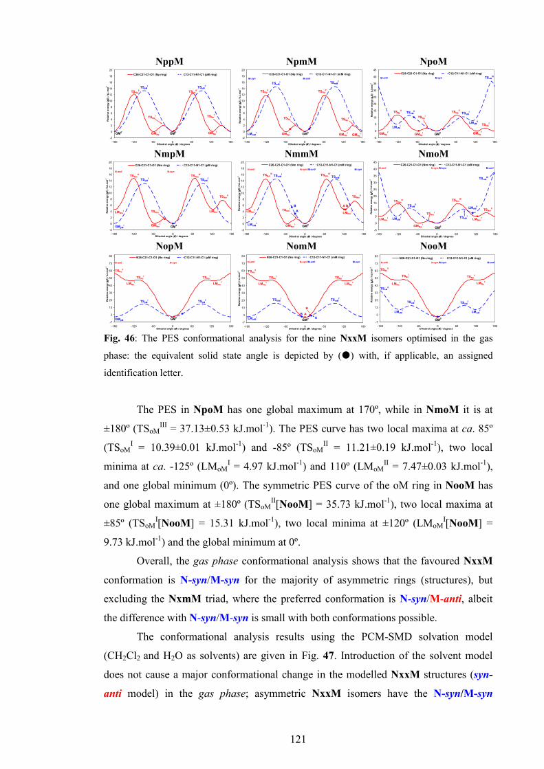
121
Fig. 46: The PES conformational analysis for the nine NxxM isomers optimised in the gas
phase: the equivalent solid state angle is depicted by (�) with, if applicable, an assigned
identification letter.
The PES in NpoM has one global maximum at 170º, while in NmoM it is at
±180º (TSoMIII = 37.13±0.53 kJ.mol-1). The PES curve has two local maxima at ca. 85º
(TSoMI = 10.39±0.01 kJ.mol-1) and -85º (TSoM
II = 11.21±0.19 kJ.mol-1), two local
minima at ca. -125º (LMoMI = 4.97 kJ.mol-1) and 110º (LMoM
II = 7.47±0.03 kJ.mol-1),
and one global minimum (0º). The symmetric PES curve of the oM ring in NooM has
one global maximum at ±180º (TSoMII[NooM] = 35.73 kJ.mol-1), two local maxima at
±85º (TSoMI[NooM] = 15.31 kJ.mol-1), two local minima at ±120º (LMoM
I[NooM] =
9.73 kJ.mol-1) and the global minimum at 0º.
Overall, the gas phase conformational analysis shows that the favoured NxxM
conformation is N-syn/M-syn for the majority of asymmetric rings (structures), but
excluding the NxmM triad, where the preferred conformation is N-syn/M-anti, albeit
the difference with N-syn/M-syn is small with both conformations possible.
The conformational analysis results using the PCM-SMD solvation model
(CH2Cl2 and H2O as solvents) are given in Fig. 47. Introduction of the solvent model
does not cause a major conformational change in the modelled NxxM structures (syn-
anti model) in the gas phase; asymmetric NxxM isomers have the N-syn/M-syn
NppM
-2
0
2
4
6
8
10
12
14
16
18
20
-180 -120 -60 0 60 120 180Dihedral angle (θθθθ ) / degrees
Relative energy (
∆∆ ∆∆E) / kJ.m
ol-1
C26-C21-C1-O1 (Np ring) C12-C11-N1-C1 (pM ring)
TSNpII
TSNpII'
TSpMI
TSpMI'
TSNpI TSNp
I'
GM0
GM0'
GMNpI GMNp
I'
NpmM
-2
0
2
4
6
8
10
12
14
16
18
20
-180 -120 -60 0 60 120 180Dihedral angle (θθθθ ) / degrees
Relative energy (
∆∆ ∆∆E) / kJ.m
ol-1
C26-C21-C1-O1 (Np ring) C12-C11-N1-C1 (mM ring)
TSNpII
TSNpII'
TSmMI TSmM
I'
GM0
GMNpI
GMNpI'
GMNpI''
TSNpI
TSNpI'
LMmMI
M-syn M-anti
NpoM
-5
0
5
10
15
20
25
30
35
40
45
-180 -120 -60 0 60 120 180Dihedral angle (θθθθ ) / degrees
Relative energy (
∆∆ ∆∆E) / kJ.m
ol-1
C26-C21-C1-O1 (Np ring) C12-C11-N1-C1 (oM ring)
TSNpI
GM0
TSoMIII
GMNpI
TSNpI'
GMNpI'
GMNpI''
TSNpII'
TSNpII
TSoMITSoM
II
LMoMI
M-anti M-syn
LMoMII
NmpM
-2
0
2
4
6
8
10
12
14
16
18
20
-180 -120 -60 0 60 120 180Dihedral angle (θθθθ ) / degrees
Relative energy (
∆∆ ∆∆E) / kJ.m
ol-1
C26-C21-C1-O1 (Nm ring) C12-C11-N1-C1 (pM ring)
GM0
TSNmIII
TSNmIII'
TSNmII
GMNmI
TSpMI
TSpMI'
GMpMI
LMNmI TSNm
I LMNmI'
N-anti N-syn
NmmM
-2
0
2
4
6
8
10
12
14
16
18
20
-180 -120 -60 0 60 120 180Dihedral angle (θθθθ ) / degrees
Relative energy (
∆∆ ∆∆E) / kJ.m
ol-1
C26-C21-C1-O1 (Nm ring) C12-C11-N1-C1 (mM ring)
TSNmIII
TSNmIII'
TSNmI
TSNmII
LMNmI'
GMNmI
GM0
LMNmI
LMmMI
TSmMI
TSmMI'
N-anti N-syn /M-anti M-syn
A
A
BB
NmoM
-5
0
5
10
15
20
25
30
35
40
45
-180 -120 -60 0 60 120 180Dihedral angle (θθθθ ) / degrees
Relative energy (
∆∆ ∆∆E) / kJ.m
ol-1
C26-C21-C1-O1 (Nm ring) C12-C11-N1-C1 (oM ring)
LMNmI
TSNmIII
GMNmI
TSNmI
TSNmIII'
LMNmI'
TSNmII
GM0
LMoMI
TSoMII
TSoMI
TSoMIII
N-anti N-syn /M-syn M-anti
LMoMII
NopM
-7
3
13
23
33
43
53
63
73
83
-180 -120 -60 0 60 120 180Dihedral angle (θθθθ ) / degrees
Relative energy (
∆∆ ∆∆E) / kJ.m
ol-1
N26-C21-C1-O1 (No ring) C12-C11-N1-C1 (pM ring)
TSpMI
TSNoII
LMNoI
TSNoI
GM0
GMpM
TSpMI'
LMNoI'
TSNoI'
N-anti N-syn
NomM
-7
3
13
23
33
43
53
63
73
83
-180 -120 -60 0 60 120 180Dihedral angle (θθθθ ) / degrees
Relative energy (
∆∆ ∆∆E) / kJ.m
ol-1
N26-C21-C1-O1 (No ring) C12-C11-N1-C1 (mM ring)
TSNoII
TSNoI
LMNoI
TSmMI
LMmMI
TSmMI'
LMNoI'
TSNoI'
GM0
N-anti N-syn /M-anti M-syn
AA
B
B
NooM
-7
3
13
23
33
43
53
63
73
83
-180 -120 -60 0 60 120 180Dihedral angle (θθθθ ) / degrees
Relative energy (
∆∆ ∆∆E) / kJ.m
ol-1
N26-C21-C1-O1 (No ring) C12-C11-N1-C1 (oM ring)
TSoMI
TSNoI
LMNoI
TSNoII
TSoMII
LMoMI
TSoMI'
LMoMI'
TSNoI'
LMNoI'
GM0
N-anti N-syn /M-syn M-anti
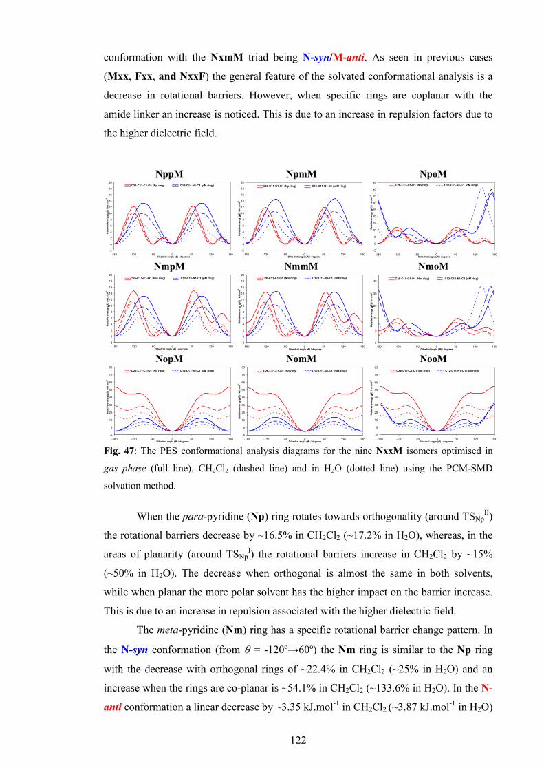
122
conformation with the NxmM triad being N-syn/M-anti. As seen in previous cases
(Mxx, Fxx, and NxxF) the general feature of the solvated conformational analysis is a
decrease in rotational barriers. However, when specific rings are coplanar with the
amide linker an increase is noticed. This is due to an increase in repulsion factors due to
the higher dielectric field.
Fig. 47: The PES conformational analysis diagrams for the nine NxxM isomers optimised in
gas phase (full line), CH2Cl2 (dashed line) and in H2O (dotted line) using the PCM-SMD
solvation method.
When the para-pyridine (Np) ring rotates towards orthogonality (around TSNp
II)
the rotational barriers decrease by ~16.5% in CH2Cl2 (~17.2% in H2O), whereas, in the
areas of planarity (around TSNpI) the rotational barriers increase in CH2Cl2 by ~15%
(~50% in H2O). The decrease when orthogonal is almost the same in both solvents,
while when planar the more polar solvent has the higher impact on the barrier increase.
This is due to an increase in repulsion associated with the higher dielectric field.
The meta-pyridine (Nm) ring has a specific rotational barrier change pattern. In
the N-syn conformation (from θ = -120º→60º) the Nm ring is similar to the Np ring
with the decrease with orthogonal rings of ~22.4% in CH2Cl2 (~25% in H2O) and an
increase when the rings are co-planar is ~54.1% in CH2Cl2 (~133.6% in H2O). In the N-
anti conformation a linear decrease by ~3.35 kJ.mol-1 in CH2Cl2 (~3.87 kJ.mol-1 in H2O)
NppM
-2
0
2
4
6
8
10
12
14
16
18
20
-180 -120 -60 0 60 120 180Dihedral angle (θθθθ ) / degrees
Relative energy (
∆∆ ∆∆E) / kJ.m
ol-1
C26-C11-C1-O1 (Np ring) C12-C11-N1-C1 (pM ring)
NpmM
-2
0
2
4
6
8
10
12
14
16
18
20
-180 -120 -60 0 60 120 180Dihedral angle (θθθθ ) / degrees
Relative energy (
∆∆ ∆∆E) / kJ.m
ol-1
C26-C11-C1-O1 (Np ring) C12-C11-N1-C1 (mM ring)
NpoM
-5
0
5
10
15
20
25
30
35
40
45
-180 -120 -60 0 60 120 180Dihedral angle (θθθθ ) / degrees
Relative energy (
∆∆ ∆∆E) / kJ.m
ol-1
C26-C11-C1-O1 (Np ring) C12-C11-N1-C1 (oM ring)
NmpM
-2
0
2
4
6
8
10
12
14
16
18
20
-180 -120 -60 0 60 120 180Dihedral angle (θθθθ ) / degrees
Relative energy (
∆∆ ∆∆E) / kJ.m
ol-1
C26-C11-C1-O1 (Nm ring) C12-C11-N1-C1 (pM ring)
NmmM
-2
0
2
4
6
8
10
12
14
16
18
20
-180 -120 -60 0 60 120 180Dihedral angle (θθθθ ) / degrees
Relative energy (
∆∆ ∆∆E) / kJ.m
ol-1
C26-C11-C1-O1 (Nm ring) C12-C11-N1-C1 (mM ring)
NmoM
-5
5
15
25
35
45
-180 -120 -60 0 60 120 180Dihedral angle (θθθθ ) / degrees
Relative energy (
∆∆ ∆∆E) / kJ.m
ol-1
C26-C11-C1-O1 (Nm ring) C12-C11-N1-C1 (oM ring)
NopM
-5
5
15
25
35
45
55
65
75
85
-180 -120 -60 0 60 120 180Dihedral angle (θθθθ ) / degrees
Relative energy (
∆∆ ∆∆E) / kJ.m
ol-1
C26-C11-C1-O1 (No ring) C12-C11-N1-C1 (pM ring)
NomM
-5
5
15
25
35
45
55
65
75
85
-180 -120 -60 0 60 120 180Dihedral angle (θθθθ ) / degrees
Relative energy (
∆∆ ∆∆E) / kJ.m
ol-1
C26-C11-C1-O1 (No ring) C12-C11-N1-C1 (mM ring)
NooM
-5
5
15
25
35
45
55
65
75
85
-180 -120 -60 0 60 120 180Dihedral angle (θθθθ ) / degrees
Relative energy (
∆∆ ∆∆E) / kJ.m
ol-1
C26-C11-C1-O1 (No ring) C12-C11-N1-C1 (oM ring)

123
is observed. This results in a small energy gap between the N-syn and N-anti
conformations of the Nm ring, 1.45 kJ.mol-1 in CH2Cl2 (0.38 kJ.mol-1 in H2O). From the
Boltzmann distribution, at 294 K approximately 35% of the molecules in CH2Cl2 and
approximately 47% of the molecules in H2O have the Nm ring in the N-anti
conformation. Therefore, conformational analysis with the PCM-SMD solvation model
predicts the plausibility of the N-anti conformation of the Nm ring. The noticeable shift
of barriers (∆θ ~5-10º) occurs due to the deviation of dihedral angles in solvents.
The rotational barrier for the ortho-pyridine (No) ring symmetrically decreases
by ~41.7% (CH2Cl2) and ~63.2% (H2O). Therefore, the solvent effect on the rotational
barrier of the No ring is the most distinct, albeit as expected: the PCM-SMD model
predicts the interaction of a strong solvent electric field with the intramolecular N-H···N
hydrogen bond in the three NoxM isomers and weakening the interaction.
The para-tolyl (pM) ring shows a regular decrease by ~27% in CH2Cl2 (~49%
in H2O). In NopM all of the barrier peaks are symmetrical, but in NppM and NmpM
the peaks are shifted by ~5º in CH2Cl2 (~10º in H2O).
In the meta-tolyl (mM) ring the pattern is similar to the pM ring with decreases
of ~28.5% in CH2Cl2 (~49% in H2O), similar barrier shifts are noted as for the pM ring.
The energy difference between M-anti and M-syn in CH2Cl2 decreases by ~43% (0.21
kJ.mol-1), while in H2O the difference is almost cancelled (93%, negligible 0.03 kJ.mol-
1), making both conformations energetically equal. Theoretically, this observation
implies that the mM ring in polar solvents can adopt both M-anti and M-syn
conformations equivalently.
The ortho-tolyl (oM) ring behaviour is more complex with the NpoM/NmoM
isomers showing differences with NooM. The rotational barriers in the M-syn
conformation decrease by ~37% (CH2Cl2) and in the M-anti conformation increase by
~8% in CH2Cl2, (~13% in H2O). However, due to a strong additional rotation of the oM
rings optimised in H2O the PES curve shape exhibits significant deviations. An extra
local maximum is positioned at -45º only and TSoMIII is displaced (by ∆θ = 40º). For the
symmetrical NooM the pattern is much simpler: as M-syn the conformation barrier
decrease is ~31% in CH2Cl2 (~54% in H2O) and in M-anti the increase is 6.7% in
CH2Cl2 (5.6% in H2O) because solvent induced high dielectric field can amplify
repulsion of the methyl group and carbonyl oxygen.
Although the NxxM isomers are insoluble in H2O, it was used as an example of
a strong polar solvent (εr=80) to illustrate and amplify solvation effects with implicit
polar solvent in the PCM-SMD model; extrapolations can be made for polar solvents

124
where the NxxM isomers are soluble. Spectroscopic data demonstrate that solvents like
DMSO can disrupt intramolecular hydrogen bonding in the NoxM series.
2.2.6.3. Energy results
The energy calculation results (CBS-QB3) (Table 26, full data is given in the
ESI I, Section 3.4.1) comprise the electronic energies (δESCF) and Gibbs free energies
(δG) in all three media, including ∆Gsolv for CH2Cl2 and H2O, as well as ∆∆Gsolv
(CH2Cl2 vs. H2O). Differences between each molecule are given as δESCF (δG) and
differences between media as ∆ESCF (∆G). The least stable molecules are NppM and
NpoM, while the most stable, regardless of media is NomM. The NoxM molecules due
to their inherent stabilisation through intramolecular N-H···Npyr hydrogen bonding are
the most stable, with significant differences as compared to the other six NpxM/NmxM
isomers.
Another stabilisation factor is the methyl group located in a meta position, although this
effect is less pronounced. In total, the effects of the pyridine N atom and CH3 group
positions on stability is summarised as: No>Nm>Np with mM>pM>oM. The estimated
∆Gsolv in CH2Cl2 and H2O, along with theoretical logKD/W (given in the ESI I, Section
3.4.1) are consistent with our experimental observations and with no unexpected results.
Table 26: The energy calculation results for the NxxM isomersa in kJ.mol-1
gas phase CH2Cl2 H2O gas
phase→CH2Cl2 gas phase→H2O CH2Cl2→H2O
δESCF δG δESCF δG δESCF δG ∆ESCF ∆Gsolv ∆ESCF ∆Gsolv ∆∆ESCF ∆∆Gsolv
NppM -4.38 0.00 -5.63 -0.69 -1.54 -1.83 -72.09 -67.33 -55.38 -47.53 16.71 19.80 NpmM -6.63 -8.38 -7.63 -0.94 -3.33 -1.85 -71.84 -59.21 -54.93 -39.17 16.92 20.04 NpoM 0.00 -2.09 0.00 0.00 0.00 0.00 -70.84 -64.55 -58.22 -43.61 12.62 20.94 NmpM -10.03 -6.64 -10.99 -1.57 -7.84 -2.81 -71.81 -61.58 -56.03 -41.87 15.77 19.70 NmmM -12.36 -7.78 -13.16 -2.11 -9.69 -1.74 -71.64 -60.98 -55.55 -39.66 16.09 21.32 NmoM -5.78 -4.23 -5.71 -1.69 -6.60 -1.16 -70.78 -64.10 -59.04 -42.64 11.73 21.47 NopM -33.97 -27.00 -24.99 -16.98 -14.44 -8.28 -61.86 -56.62 -38.69 -26.98 23.17 29.64 NomM -36.31 -27.31 -26.99 -20.21 -16.64 -15.08 -61.52 -59.54 -38.55 -33.48 22.97 26.06
NooM -30.37 -29.93 -20.73 -17.29 -9.81 -8.31 -61.21 -54.00 -37.67 -24.08 23.54 29.92 a Only the differences between each molecule (δ) and media (∆,∆∆) are shown. NppM and
NpoM isomers are taken as basis point.
2.2.7. Comparisons of the solid state and modelling data
Comparison of the NxxM isomer structures from crystal structure data and
calculations is made by marking (as �) torsion angle differences (∆θ) between the

125
experimental and theoretical structures on the corresponding gas phase PES diagrams
(Fig. 46). For NmmM and NomM with Z’>1 the corresponding angles are labelled as A
or B. Most crystallographic dihedral angles correlate with their computational results by
having similar conformations with an average offset of torsion angles of ±20-40º. This
holds for the NoxM triad with NooM having both a planar crystal and calculated
molecular structure. Generally, no significant differences (∆θ) are seen in the NoxM
isomers. The 5-Cl-NoxM side products were not subjected to conformational analysis;
their crystal structure conformations generally correspond with the optimised models of
the related NoxM isomers.
In the NpxM crystal structures, the Np-ring conformation corresponds with its
optimised gas phase model; however, it can found in either the GM0 or GMNp
equivalent positions. In the case of the NmxM isomers the Nm-ring adopts the unstable
TSNmI position in NmpM or LMNm
I’ in both NmmM and NmoM. The unstable planar
conformation of the Nm-ring in both NmpM and NmpFM crystal structures is due to
the catemeric chain formation driven by N-H···N/C-H···N hydrogen bonding. The No-
ring conformations in the NoxM crystal structures correspond with their modelled
equivalents.
In almost all molecules with the exception of NpoM and NmoM, the M-ring
conformation is the same in both the solid state and optimised gas phase models with a
maximum deviation of ±40º. In fact all NxmM crystal structures have the mM-ring as
M-anti as predicted by conformational analyses despite the small differences with the
M-syn structure (0.37-0.46 kJ.mol-1). This is the reverse of the NxmF isomers where
opposite conformations and/or disorders are noted.
Generally, for the Nm-ring the main conformational differences are seen in the
NmmM and NmoM isomers. The calculated NmmM conformation is N-syn/M-anti,
whereas the solid state (Z’ = 2) has a meta-stable N-anti/M-anti conformation for both
molecules (Fig. 39), with A and B residing in the LMNmI’ potential well (Fig. 46) There
is a high probability of the N-anti conformation especially in polar solvents, allowing
isolation of this conformation in the solid state. The reverse arrangement of the N-ring
solid state conformation as N-syn would not facilitate the amideN-H···Npyridine hydrogen
bond and would introduce short H···H sterically hindered contacts in the crystal
structure (if allowed); the N-H···N interactions are crucial for the formation of the
crystal structure backbone. The same phenomenon exists for the structurally similar
Mmm and NmmF.

126
For NmoM the crystallographic conformation is N-anti/M-anti and opposite to
the N-syn/M-syn in the modelled structure (Fig. 46, meta-stable potential wells at
LMoMII and LMNm
I’). As for NmmM, conformational analysis shows the N-anti
conformation is likely, especially in polar solvents, while the M-anti conformation can
be expected as well. The primary interaction of NmoM is N-H···O=C which generates a
1-D chain along the b-axis. In this arrangement the ortho-CH3 group is positioned as M-
anti because the alternate M-syn conformation brings the CH3 group closer to the N-
H···O=C interaction and effects a steric clash. Therefore, the LMoMII potential well
represents the only niche available for the relatively sterically bulky ortho-CH3 group
(compared to H). Similarly, the Npyr is located as N-anti, as the opposite N-syn
conformation negates some weak but favourable C-H···π interactions and places it too
close to the carbonyl C atom of a neighbouring molecule.
For comparison NpoM has N-H···O=C as the primary interaction (as in
NmoM). In NpoM the ortho-CH3 is positioned as M-syn but in a highly distorted and
relatively unstable conformation, being almost orthogonal to the amide linker.
However, conformational analysis with the PCM-SMD solvation model suggests that
this conformation in polar solvents may be plausible. For NpoM the ortho-methyl group
also participates in crystal structure formation making additional weak C-H···O=C
contacts with the C=O of an adjacent NpoM molecule (C17 in Fig. 36).
An overview of the benzamide and pyridinecarboxamide results is presented in
the “Discussion and Conclusions”.

127
Chapter II: Carbamates

128
1. General description of carbamate syntheses
The simplest synthetic method for the formation of phenyl-N-pyridinyl-carbamates
(CxxR) (Scheme 32) is the condensation reaction of aminopyridines with commercially
available phenyl chloroformates in the presence of base (Et3N) and solvent (CH2Cl2).196-
198 This method is analogous to the Schotten-Baumann reaction as applied to the
previous isomer grids. The condensation reaction gives relatively pure products in high
yields. Unfortunately only a limited number of phenyl chloroformates are commercially
available, i.e. para-substituted and only two ortho-substituted phenyl chloroformates.
Therefore, 14 compounds were synthesised using the condensation approach starting
from the 3-/4-aminopyridines (Method 1, Section 1.1). Alternatively, if 2-
aminopyridine is used, double carbamates are obtained where both hydrogen atoms in
the amine moiety are substituted with chloroformates. The result is similar to the
formation of the (2:1) Mxod and Fxod by-products (Chapter I, Section 1). As with the
benzamides, this is due to the pyridine nitrogen in the ortho position. In order to
minimise the formation of double carbamates, the reaction is carried out without solvent
and base, applying only the mechanical mixing of two compounds at lower temperature
(Method 2, Section 1.3). The resulting mixture was then purified by re-crystallisation.
There were several options available for the synthesis of the remaining CxxR
compounds. One of these approaches is the use of an agent that transforms phenols into
the desired chloroformates, phosgene or a substitute, diphosgene or triphosgene. Due to
health and safety reasons these methods were not used. A simple and straightforward
method for carbamates synthesis is the Curtius rearrangement reaction (or Curtius
reaction or degradation),199 a chemical reaction that involves the rearrangement of an
acyl azide to an isocyanate (Scheme 31).200 The acyl azide (pyridinyl azide) can be
formed from the carboxylic acid by a suitable agent like diphenylphosphoryl azide
(DPPA).201
N
O
N
N
NC
O
-N2(g)
∆
Scheme 31: Rearrangement of benzyl azide into a reactive benzylisocyanate molecule

129
Pyridinecarboxylic acids can be easily converted into pyridinyl azides using
diphenylphosphoryl azide, at higher temperature (70°C) in the presence of a base. The
pyridinyl azides spontaneously rearrange into reactive pyridinyl isocyanates. Reaction
of pyridinyl isocyanate with phenol gives the phenyl-N-pyridinyl-carbamate (CxxR,
Section 1.3).
Usually the Curtius rearrangement reaction (Curtius reaction, variant A, see
section 1.3) is performed as a two step (one pot) reaction, with isonicotinic or nicotinic
acids as starting materials, diphenylphosphoryl azide as converting agent, and Et3N as
base in anhydrous acetonitrile at 70°C. Immediately after the pyridinyl isocyanate is
formed, the addition of a phenol starts the final condensation into a phenyl-N-pyridinyl-
carbamate. Similar syntheses have been described in the literature.202-204
This method was convenient when isonicotinic or nicotinic acids (3-/4-
pyridinecarboxylic acids) were used as starting materials, giving acceptable yields.
However, if picolinic acid (2-pyridinecarboxylic acids) was used in order to synthesise
phenyl-N-pyridin-2-yl-carbamates (CoxR) the yield was low (~2%). This was overcome
by a longer reaction time, using toluene instead of acetonitrile as solvent and performing
the reaction at 110°C (variant A, Section 1.3).205
1.1. Method 1. Condensation of AP’s with phenyl chloroformates
1. To a stirring solution of 3-/4-aminopyridine (490 mg, 5.2 mmol) in 150 ml of
CH2Cl2, triethylamine was added (0.740 ml, 5.2 mmol) and then R-phenyl
chloroformate [R = 4-F, 4-Cl, 4-Br, 4-OCH3, 4-CH3, 2-Cl or 2-OCH3] (5.2 mmol) was
added dropwise under an atmosphere of N2. The resulting mixture was stirred for 3
hours.
2a. If a white product formed it was filtered and washed with CH2Cl2 (in most
cases it was the pure product).
2b. The organic reaction mixture was washed three times with 250 ml of 3%
KHCO3, and dried with anhydrous MgSO4. After removal of the solvent, the product
was recovered.
If necessary, purification was accomplished by column chromatography using
silica as stationary phase and a mixture of CH2Cl2 and MeOH (8:1) as mobile phase.
This method (Scheme 32) was used for the synthesis and purification of the following
14 compounds: CppF, CppCl, CppBr, CppOMe, CppM, CmpF, CmpCl, CmpBr,
CmpOMe, CmpM, CpoCl, CmoCl, CpoOMe and CmoOMe.

130
N
NH2
OR Cl
O
HN O
ON
R
Et3N, 0°C, CH2Cl2
Scheme 32: Condensation of 3-/4-AP with phenyl chloroformates forming CxxR
1.2. Method 2. Condensation of 2-AP with phenyl chloroformates in solventless
conditions
R-phenyl chloroformate [R = 4-F, 4-Cl, 4-Br, 4-OCH3, 4-CH3] (5.23 mmol)
was added using a pipette to a cooled 2-aminopyridine solid (10.46 mmol) in a test tube
(on an ice bath) and the mixture was vigorously agitated. The resulting solid was
dissolved in a mixture of CH2Cl2 (250 ml) and aqueous KHCO3 (1%, 250 ml). The
emulsion was allowed to separate in a funnel, and the organic layer was washed three
times with an aqueous solution of KHCO3 and twice with brine. The organic layer was
dried with MgSO4 and the crude product obtained after evaporation of the solvent.
The crude product was washed with a cooled mixture of hexane, acetone and
ethyl acetate (3:1:1). If necessary the precipitate was dissolved in warm CH2Cl2 and re-
crystallisation induced. Crystals of pure product were collected on a Hirsch funnel. This
method (Scheme 33) was used for the synthesis and purification of the following five
compounds: CopF, CopCl, CopBr, CopOMe and CopM (CopR).
N
NH2
R
O Cl
ON
HN
N
NO O
OOR R
O
R
O
2-aminopyridine solventless conditions, 0°C
N-(phenyl)-N-(pyridin-2-yl)carbamate
phenyl (pyridin-2-yl)carbamate
Scheme 33: Condensation of 2-aminopyridine with phenyl chloroformates

131
1.3. Method 3. Curtius rearrangement reaction, variant A
1. A mixture of isonicotinic or nicotinic acid (1.2877 g, 10.46 mmol), Et3N (1.46
ml 10.46 mmol) and diphenylphosphoryl azide (2.258 ml, 10.46 mmol) was stirred for 1
hour in 30 ml of dry acetonitrile at room temperature (Scheme 34). The reaction
mixture was carefully heated (water bath) to reflux for 1 hour and R-phenol (R = 3-F, 2-
F, 3-Cl, 3-Br, 2-Br, 3-OCH3, 2-CH3 and 3-CH3) (10.46 mmol) was added. The solution
was refluxed for 7 hours and gradually cooled down and allowed to stir overnight.
2a. If a white precipitate formed it was filtered, washed with acetonitrile and
dried (usually found to be the pure product).
2b. The solvent was removed from the reaction mixture under reduced pressure,
the residue dissolved in CH2Cl2, washed thrice with a solution of KHCO3 and Na2CO3
(pH=9) and twice with brine/ammonium chloride (pH=5). The organic fraction was
evaporated and the compound re-crystallised from diethyl ether and CH2Cl2. If
necessary, the purification was accomplished by column chromatography using silica
and a mixture of CH2Cl2 and methanol (8:1) as mobile phase. There were 16
compounds obtained using this method: CpmF, CmmF, CpoF, CmoF, CpmCl,
CmmCl, CpmOMe, CmmOMe, CpmBr, CpoBr, CmmBr, CmoBr, CpmM, CpoM,
CmmM, CmoM.
N
O
OH
DPPA, Et3N, ACN, reflux, 1h
R
OH
N
NC
O
isocyanatopyridine
N
HN O
O
R
R = F, Cl, Br, CH3, OCH3,
phenyl pyridinylcarbamate
Pyridinecarboxylic acid
Scheme 34: Curtius rearrangement reaction, variant A, synthesis of the CxxR compounds.

132
1.4. Method 4. Curtius rearrangement reaction, variant B
A mixture of picolinic acid (2.5754 g, 20.92 mmol), Et3N (2.92 ml 20.92 mmol),
and diphenylphosphoryl azide (4.516 ml, 20.92 mmol) was refluxed in 40 ml of dry
toluene at 100°C for 4 hours. The R-phenol (R = 3-Cl, 2-Cl, 3-Br, 3-OCH3, 2-OCH3, 3-
CH3 and 2-CH3) (20.92 mmol) was added and the reaction mixture was refluxed
(Scheme 35) for an additional 4 hours and left to cool overnight.
If a precipitate formed then it was filtered using a Hirsch funnel. The precipitate
was found to contain the product. The filtrate was subjected to further purification. Into
the filtrate 100 ml of CH2Cl2 was added and the organic mixture was washed thrice with
a solution of KHCO3 and K2CO3 (pH=9) and twice with brine. The organic fraction was
dried with MgSO4, filtered and solvent removed.
The black product was washed (re-crystallised) with diethyl ether and dark
crystals were obtained. The presence of the product was confirmed by TLC and the
combined products were purified by column chromatography (silica/CHCl3). Seven
compounds (CoxR) were obtained using this method: ComM, CooM, ComOMe,
CooOMe, ComBr, CooCl and ComCl.
N
O
OH
DPPA, Et3N, toluene, 110°C, 4h
R
OH
N
NC
O
NHN O
O
R
[R = F, Cl, Br, CH3, OCH3]
Picolinic acid
2-isocyanatopyridine
phenyl pyridin-2-ylcarbamate
4 h
Scheme 35: Curtius rearrangement reaction, variant B, synthesis of some phenyl-
pyridin-2-ylcarbamates (CoxR)

133
2. Comment on synthesis and general characteristics
Table 27 summarises the amounts, yields and melting points of the CxxR
compounds.
Table 27: Yields and melting points of the CxxR compounds
m/g % m.p./ºC m/g % m.p./ºC CppF 0.923 76 183.0-185.3 CpoF 0.404 16 166.3-169.0 CppCl 1.019 78 196.9-199.6 CmoF 0.806 33 134.1-136.5 CppBr 1.106 72 204.5-206.4 CmmCl 1.106 42 168.9-171.2 CppOMe 1.074 84 155.1-156.7 CpmCl 0.600 23 193.0-197.5 CppM 1.118 94 163.5-165.7 CmmM 1.700 71 112.5-113.0 CmpF 0.546 45 165.3-167.4 CpmM 0.474 20 131.3-134.6 CmpCl 0.971 37 173.2-175.4 CmoM 1.098 46 79.0-84.0 CmpBr 0.660 43 167.5-170.4 CpoM 0.863 36 128.0-131.0 CmpOMe 0.820 32 159.5-162.5 CmmOMe 1.164 45 139.5-142.5 CmpM 0.610 51 167.7-170.6 CpmOMe 0.870 34 130.1-134.7 CopF 0.450 29 178.9-179.9 CmmBr 1.208 39 152.2-154.7 CopCl 0.290 22 197.2-199.8 CmoBr 0.642 21 86.2-86.9 CopBr 0.200 13 194.3-196.6 CpoBr 0.700 23 167.6-168.5 CopOMe 0.350 27 182.3-184.7 CpmBr 1.212 39 191.6-193.4 CopM 0.362 30 190.0-191.8 ComCl 0.345 23 173.4-175.4 CpoCl 0.870 67 168.2-170.3 CooCl 0.243 20 144.4-146.1 CpoOMe 1.073 84 187.3-191.8 ComM 1.487 31 139.7-143.8 CmoCl 0.365 28 123.4-125.6 ComOMe 1.2269 24 144.2-145.4 CmoOMe 0.283 22 107.5-109.6 CooM 1.664 33 160.1-162.3 CpmF 0.300 25 160.5-162.9 CooOMe 0.697 14 157.3-159.8 CmmF 1.200 49 151.3-152.3 ComBr 0.32 5 175.1-175.5
The CpxR compounds synthesised with Method 1 usually had a good to
excellent yield, especially the methyl and methoxy derivatives (~73%, CppM = 94%).
However, the CmxR compounds synthesised with the same method had a lower yield
(~37%). Finally, compounds synthesised by Method 2 (CopR) had, due to the losses
during the re-crystallisation, lower yields (~24%). The compounds obtained by the
Curtius rearrangement reaction (Method 3) had moderate yields (~35), while the CoxR
compounds (Method 4) had lower yields (~21%). Attempts to synthesise CooF, CooBr
and ComF were not successful, resulting in very small and unsatisfactory yields.
The CxxR compounds are usually white powders, less crystalline than the benzamides
and pyridinecarboxamides (with the exception of some methyl and methoxy derivatives)
and with a specific phenolic odour. Despite the rigorous purifications, the phenolic
odour originates from a small amount of decomposition giving traces of phenols.
Two major characteristics of the CxxR derivatives that differentiate them from
the previous groups of compounds are the relatively poor solubility of most of the
compounds and their instability (spontaneous decomposition).

134
The CxxR carbamates are insoluble in water and cyclohexane, while their
solubility is poor in solvents such as diethyl ether, CH2Cl2 (with the exception of most
CmxR compounds), toluene, but slightly better in ethyl acetate. Solubility in CH3CN,
CHCl3 and CH3COCH3 can be regarded as moderate, while solubility is good in MeOH
(for most compounds) and excellent in DMSO.
Unfortunately, stability was approximately the reverse. The carbamates were
found to be very unstable in polar solvents such as alcohols and DMSO with
decomposition in DMSO found to be very fast (within hours). Hence, NMR data were
not collected in DMSO-d6, as was the case with the benzamides (Chapter I), but in
acetone-d6 affording a better solubility/stability ratio. Since stability in non-polar
solvents was satisfactory while solubility was modest, crystal growth was tried from
limited choices of solvents, such as CH3COCH3, CHCl3, CH3CN, or mixtures of these
solvents.
3. Comment on spectroscopic data
All spectroscopic data including 1H-, 13C-, 19F-NMR and IR are listed in
Appendix I, Section 3 and the spectra are given in the ESI II, Section 1. Due to the
insolubility/instability of the CxxR compounds, the NMR data were recorded in CDCl3
(1H-NMR) and acetone-d6 (1H-, 13C- and 19F-NMR).
As for the benzamide and pyridinecarboxamides (Chapter I), the chemical shift
of the carbamate hydrogen changes position depending on the solvent. In the less polar
CDCl3 the carbamate proton of the CpxR and CmxR isomers ranges from 7.3-8.0 ppm,
while in more polar solvents such as acetone, it is usually at 9.5-10 ppm. However, in
CoxR the carbamate proton shifts are usually found around 10 ppm regardless of
solvent. These findings are in agreement with hitherto observations in benzamides and
pyridinecarboxamides where almost the same pattern was observed in all isomers where
the pyridine nitrogen was located ortho. The cause of this effect is delocalisation of
electrons between the carbamate and pyridine nitrogens.
With regard to the IR spectra, all compounds show a strong band ca. 1745 cm-1
that corresponds with the stretch of the carbonyl (C=O) bond. The N-H vibrations in the
region between 3300 cm-1 and 2700 cm-1 are usually strongly linked to hydrogen
bonding in the crystal structure. The relationship between this “N-H” region and
primary intermolecular interactions in solid state will be discussed later.

135
4. X-ray crystallographic methods
All CxxR crystal samples were obtained by slow evaporation at room
temperature or 4ºC, typically from CHCl3, acetone, ethyl acetate, methanol, THF or
solvents blends including n-hexane and toluene. The single crystal growths were
successful for most of CxxM (except for CmmM and ComM) and CxxOMe (except
CmoOMe) isomers. For the halogen derivatives (CxxX) success was limited, with only
10 out of 25 halogen-carbamates giving suitable single crystals, after many
crystallization attempts from several solvents, under a wide range of crystallization
conditions. These compounds are CmpF, CmmF, CopF, CpmCl, CmpCl, CmmCl,
CopCl, CmoBr, CmpBr and CopBr.
Single crystal X-ray data collection and data reduction,176 structure solution and
refinement3,168 for all CxxR compounds was as described for the Fxx and NxxM isomer
grids (Chapter I). Selected crystallographic and structural information is detailed in the
ESI II (Section 2). Molecular and hydrogen bonding diagrams (Figs. 48-54, 56-64 and
66-75) were generated as described for other isomer grids (with displacement ellipsoids
drawn at the 30% probability level).169
5. Computational methods
A computational study similar to that carried out for the benzamides (Mxx and
Fxx) and pyridinecarboxamides (NxxF and NxxM) was performed for all five phenyl-
N-pyridinyl-carbamate (CxxR) isomer grids. The aim, as in Chapter I, was to
investigate the optimised molecular geometry of the isomers, perform conformational
analysis and elucidate conformational preference in gas phase and to investigate the
flexibility of the main torsion angles and energies of rotational barriers. Finally the
modelling information, presented in the form of PES diagrams, was directly compared
with the solid-state molecular geometries in order to rationalise both similarities and
differences of the modelled and solid state molecular structures, as well as problems
with the crystallinity of carbamates.
Unlike the computational methods used in Chapter I, phenyl-N-pyridinyl-
carbamate (CxxR) isomer grids were not subjected to optimisations using implicit
solvent models (PCM-SMD, CH2Cl2 and H2O); the modelling was limited to gas phase
calculations since gas phase modelling affords the most significant information
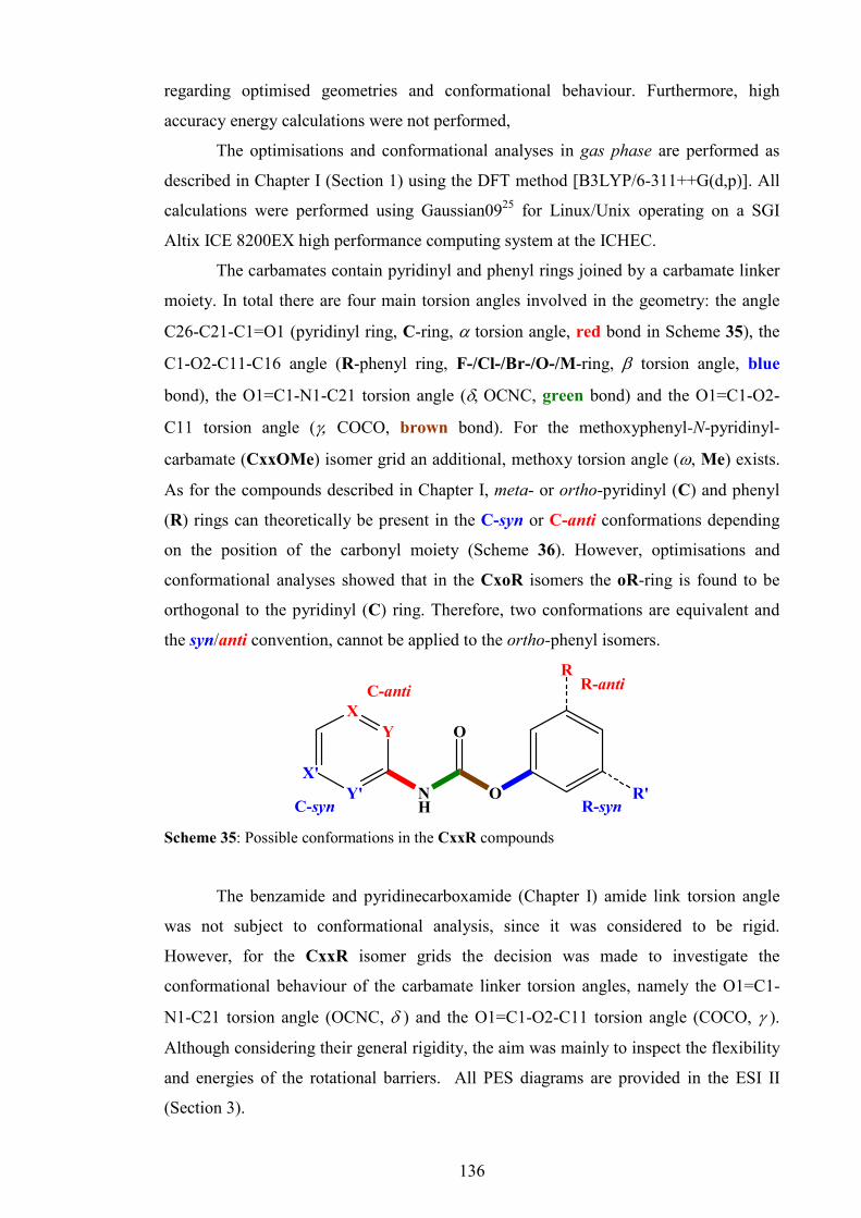
136
regarding optimised geometries and conformational behaviour. Furthermore, high
accuracy energy calculations were not performed,
The optimisations and conformational analyses in gas phase are performed as
described in Chapter I (Section 1) using the DFT method [B3LYP/6-311++G(d,p)]. All
calculations were performed using Gaussian0925 for Linux/Unix operating on a SGI
Altix ICE 8200EX high performance computing system at the ICHEC.
The carbamates contain pyridinyl and phenyl rings joined by a carbamate linker
moiety. In total there are four main torsion angles involved in the geometry: the angle
C26-C21-C1=O1 (pyridinyl ring, C-ring, α torsion angle, red bond in Scheme 35), the
C1-O2-C11-C16 angle (R-phenyl ring, F-/Cl-/Br-/O-/M-ring, β torsion angle, blue
bond), the O1=C1-N1-C21 torsion angle (δ, OCNC, green bond) and the O1=C1-O2-
C11 torsion angle (γ, COCO, brown bond). For the methoxyphenyl-N-pyridinyl-
carbamate (CxxOMe) isomer grid an additional, methoxy torsion angle (ω, Me) exists.
As for the compounds described in Chapter I, meta- or ortho-pyridinyl (C) and phenyl
(R) rings can theoretically be present in the C-syn or C-anti conformations depending
on the position of the carbonyl moiety (Scheme 36). However, optimisations and
conformational analyses showed that in the CxoR isomers the oR-ring is found to be
orthogonal to the pyridinyl (C) ring. Therefore, two conformations are equivalent and
the syn/anti convention, cannot be applied to the ortho-phenyl isomers.
X'
XY
Y' NH
O
O
R'
RC-anti R-anti
C-syn R-syn
Scheme 35: Possible conformations in the CxxR compounds
The benzamide and pyridinecarboxamide (Chapter I) amide link torsion angle
was not subject to conformational analysis, since it was considered to be rigid.
However, for the CxxR isomer grids the decision was made to investigate the
conformational behaviour of the carbamate linker torsion angles, namely the O1=C1-
N1-C21 torsion angle (OCNC, δ ) and the O1=C1-O2-C11 torsion angle (COCO, γ ).
Although considering their general rigidity, the aim was mainly to inspect the flexibility
and energies of the rotational barriers. All PES diagrams are provided in the ESI II
(Section 3).

137
6. CxxM isomer grid
6.1. Molecular and crystal structure data
Seven of the nine CxxM isomers gave single crystals suitable for single crystal
X-ray diffraction. The CmmM and ComM isomers did not produce any suitable single
crystals, even after numerous attempts with a range of organic solvents. Unexpectedly,
the CpoM and CmoM were isolated as solvates, CpoM with a disordered molecule of
chloroform and CmoM as a monohydrate.
All structures crystallise in the monoclinic system, with exception of CmpM
(orthorhombic). Apart from the disordered solvent in the CopM crystal structure, no
disorder was found in the solid state CxxM structures. Tables 28 and 29 summarise the
basic crystallographic data and structural features.
Table 28: Selected crystallographic data for the seven CxxM isomers†
CxxM Space group Z’ Volume (Å3) R[F2 > 2σ(F
2)], wR(F
2)
CppM P21/c 1 1149.0(7) 0.065, 0.132 CpmM P21/n 1 1150.42(8) 0.064, 0.095 CpoM P21/n 2 2649.4(12) 0.075, 0.237 CmpM P212121 1 1182.66(3) 0.025, 0.068a CmoM P21/c 1 1268.09(4) 0.048, 0.134 CopM P21/c 1 1164.39(11) 0.091, 0.338 CooM P21/n 1 1176.92(3) 0.044, 0.127
† Complete crystallographic, refinement and structural details for the seven CxxM isomers
(C13H12N2O2) are listed in the ESI II (Section 2.1.1). aObtained with Cu Kα radiation
Table 29. Relevant structural features (Å,°) in the eight CxxM isomersa
CxxM C6/C5N C6/carbamate C5N/carbamate N…N/Ob Packing
CppM 73.94(8) 62.89(10) 20.85(13) 2.955(3) C(6) chains
CpmM 53.44(8) 55.24(7) 4.53(15) 2.972(3) C(6) chains 84.97(12) 87.68(14) 8.10(24) 2.900(4) CpoM 82.38 (10) 69.46(11) 13.14(19) 2.908(4)
2-D sheets
CmpM 52.33(5) 63.16(5) 11.38(11) 2.9138(17) 2-D sheets CmoM 66.25(4) 86.55(4) 26.12(5) 2.8279(15)c
2.8269(16)d R
44(14) dimers
/2-D Sheets CopM 62.53(12) 67.60(11) 8.58(27) 3.003(4) dimers CooM 76.45(4) 81.68(4) 5.42(11) 2.9770(16) dimers a Full structural details are provided in the ESI II (Section 2.1.2). b The carbamateN…Npyridine interaction distances. c The carbamateN···Owater interaction distances. d The waterO···Npyridine interaction distances.

138
6.1.1. CpxM isomer series The main interaction in the CpxM isomers is the carbamateN1-H1···N24pyridine
hydrogen bond, with (CppM) or without (CpmM) significant C-H···O2 auxiliary
interactions while in CpoM (Z’ = 2) both types of bonding are present, alternately
linking molecules as (···ABAB···). The CpoM isomer crystallises with a solvate with
one disordered CHCl3 molecule.
CppM molecular and crystal structure
Single crystals were grown from acetone. The primary aggregation is
accomplished via N1-H1···N24 hydrogen bonding [N1···N24a = 2.955(3) Å, a = -
1+x,1/2-y,-1/2+z], enhanced by an auxiliary C25-H25···O2a [C25···O2a = 3.213(3) Å]
interaction (Fig. 48). The N1-H1···N24 hydrogen bond links molecules in a zig-zag
manner into a C(6) chain, parallel with the (010) plane and perpendicular to the b-axis
direction. A secondary interaction involves π-π stacking (C21···C25b = 3.161(3) Å, b =
x,1/2-y,-1/2+z), as well as the C16-H16···O1c [C16···O1c = 3.582(4) Å, c = 1+x,y,z]
interaction. Of less importance are the weak C23-H23···C12d (d = -1+x,y,-1+z) and
C15-H15···H15-C15e (e = -2-x,-y,-z) contacts. It is interesting that the disordered
methyl group (around the bond axis) does not engage in any intermolecular interaction.
The carbamate linker atoms form a four atom carbamate plane (N1/C1/O1/O2).
The angle between the carbamate plane and the M-ring (tolyl ring) is 62.89(10)º, while
against the pyridinyl ring it is 20.85(13)º. The angle between the M-ring and the
pyridinyl ring is 73.94(8)º (Table 29). Compared with Mpp [46.03(9)º] and NxxM
[66.45(3)º] the M-ring appears to be more rotated than in the benzamides.
Fig. 48: An ORTEP diagram of CppM with N1-H1···N24a hydrogen bonding (a = -1+x, ½-y,-
½+z) and an auxiliary C25a-H25a···O2 interaction.

139
CpmM molecular and crystal structure
Suitable single crystals were grown from CDCl3. As for CppM, the primary
interaction is N1-H1···N24 hydrogen bonding (N1···N24c = 2.972(3) Å, c = -x+1/2,y-
1/2,-z+1/2), and contrary to CppM, no auxiliary bonding to O2 is present (Fig. 49).
However, a weak N1-H1…C23 contact is present.
Fig. 49: An ORTEP diagram of CpmM showing aggregation via N1-H1···N24 hydrogen bonds
(b = ½-x, ½+y, ½-z; c = ½-x,-½+y, ½-z)
The N1-H1···N24 hydrogen bonds form a zig-zag C(6) chain, along the b-axis
direction and parallel to the (301) plane. A contact C14-H14···H17-C17 (H14···H17a =
2.27 Å, a = -x,1-y,2-z) exists along the (301) plane. Finally, weak but double C16-
H16···C1 contacts (C16···C1d = 3.485(3) Å, d = -x,1-y,1-z) connect chains into a 3-D
structure. The methyl group is disordered around the C14-C17 axis.
The angle between the carbamate plane and the pyridinyl ring (C-ring) is
4.53(15)°, therefore, most of the molecule is planar apart from the M-ring at an angle of
55.24(7)° to the carbamate plane. The interplanar angle between the M-ring and the C-
ring is 53.44(8)°. The conformation of the M-ring is M-anti.
CpoM molecular and crystal structure
The CpoM isomer is the only isomer isolated as a solvate as [(CpoM)4:CHCl3].
The molecule of CHCl3 is disordered with total occupancy of 50%; the ratio between
CpoM and CHCl3 is 4:1 (Fig. 50).

140
Two CpoM molecules (A and B) are connected into a pair with similar N1-
H1···Npyr hydrogen bonding N1A-H1A···N24B [N1A···N24B = 2.900(4) Å] as in the
CpmM molecule, with an additional weak N1A-H1A···C25B contact. The interplanar
angle between the two pyridinyl rings (A and B) is 28.67(16)º. Two pairs of molecules
(AB) are linked into an undulating C(6) chain (···ABAB···) through N1B-H1B···N24b
[N1B···N24b = 2.908(4) Å, b = -3/2+x,1/2-y,-1/2+z] hydrogen bonding, augumented
with flanking C23A-H23A···O2Bb [C23A···O2Bb = 3.222(4) Å] interactions (Fig. 50)
as described for the CppM isomer. The waving 1-D chain is perpendicular to the b-axis
and parallel to the ( ̅103) plane. The secondary interaction is the C16B-H16B···O1Bv
(C16B···O1Bc= 3.325(5) Å, c = -1+x,y,z) contact aggregating chains along the a-axis
direction into a 2-D sheet parallel to the (010) plane.
Fig. 50: An ORTEP diagram of CpoM showing the N1-H1···N24 hydrogen bonds and
disordered molecule of CHCl3 (a = 1-x,-y,-z; b = -3/2+x, ½-y,-½+z)
The disordered CHCl3 molecules engage in a final aggregation through weak but
double C13A···Cl1S [3.426(9) Å] and C17B-H17B…Cl(1S) interactions (Fig. 50).
The ortho-tolyl ring (M-ring, C6) in molecule A is almost orthogonal to the
carbamate plane [87.68(14)°], while in the molecule B the M-ring/carbamate ring is
69.46(11)°. The pyridinyl rings (C-ring, C5N) are generally planar with the carbamate
plane (Table 29). Both interplanar angles (C5N/C5) (Table 29) are close to 90°, the rings
are nearly orthogonal. The interplanar angle between the M-rings is 56.15(14)°.

141
6.1.2. CmxM isomer series
Since crystal growth of CmmM was not successful, only the CmpM and
CmoM results are presented. CmoM is unique in the CxxM isomer grid since it was
isolated as a monohydrate with a remarkable hydrogen bonding system. With the
exception of CmoM, only CmoBr was isolated as monohydrate among all the
carbamate grids.
CmpM molecular and crystal structure
The CmpM crystal structure data was collected with Cu Kα radiation, affording
a structure solution with an R-factor of 0.025.
Fig. 51: An ORTEP diagram of CmpM (a = 1-x,-½+y,½-z; b = -1+x,y,z)
The single crystals were grown from acetone. The primary interaction is N1-
H1···N23a [N1···N23a = 2.9138(17) Å, a = 1-x,-1/2+y,1/2-z] hydrogen bond,
aggregating molecules into a spiral C(5) chain, along the b-axis direction, parallel with
the (001) plane (Fig. 51). The N1-H1···N23 hydrogen bond is supported by the weak
N1-H1···C22a side interaction [N1···C22a = 3.3604(18) Å], as seen in CpmM.
The secondary interaction is C16-H16···O1b [C16···O1 = 3.440(2) Å, b = -
1+x,y,z] connecting the chains along the a-axis direction into a 2-D sheet, parallel with
the (001) plane (Fig. 51). Weak C-H···π(arene) contacts C24-H24···Cg1c [C24···Cg1c =
3.7300(16) Å, Cg1 = (C21,…,C26), c = 2-x,1/2+y,1/2-z] and C25-H25···Cg2c
[C25…Cg1c = 3.4083(16) Å, Cg2 = (C11,…,C16)] support sheet formation. The
conformation of the C-ring is C-syn.

142
CmoM molecular and crystal structure
The CmoM isomer is the only compound in the CxxM isomer grid isolated as a
hydrate (CmoM:H2O). The single crystals were grown from a CHCl3/acetone solvent
mixture. Molecules of water play a crucial role in the aggregation of the CmoM:H2O
crystal structure. Two molecules of water and two molecules of CmoM form a complex
structure through double N1-H1···O2W [N1···O1W = 2.8279(15) Å] and O1W-
H2W···N23 [O1W···N23a = 2.8269(16) Å, a = 2-x,1-y,-z] hydrogen bonds giving rise
to a R44(14) ring (Fig. 52).
Fig. 52: An ORTEP diagram of the CmoM monohydrate (a, b = 2-x,1-y,-z, c = x,½-y,-½+z).
Two pyridinyl rings in the complex are coplanar with a minor offset; molecules
of water are on either side of and below the pyridinyl ring planes. An auxiliary
interaction O1W-H2W···C22a [O1W···C22a = 3.5219(16) Å] supports the O1W-
H2W···N23 hydrogen bonding.
The secondary interaction is the O1W-H2W···O1d [O1W···O1d = 2.9126(15) Å,
d = x,1/2-y,1/2+z] hydrogen bond (Fig. 52). It is critical and even more important for
aggregation, supported by weak but double C26-H26···O1d [C26···O1d = 3.3532(15) Å]
interaction it links complexes directly into a 2-D sheet, parallel with the (100) plane.
The 2-D sheets are connected into a 3-D crystal structure by weak C17-H17D…C14e
[H17D…C14e = 2.82 Å, e = 1-x,-y,-z] contacts.
Within the molecule, a weak intramolecular C17-H17A…O2 (H17A…O2 =
2.65 Å) interaction is observed. The C6/C5N interplanar angle is 66.25(4)°, while the

143
C6/carbamate angle is 86.55(4)°. The C5N/carbamate angle is unusually large with a
value of 26.12(5)°. The conformation of the C-ring is C-syn.
6.1.3 CoxM isomer series
The main feature of both CoxM isomers is dimer formation through double N1-
H1…N22 hydrogen bonding as a primary intermolecular interaction, forming cyclic
R2
2(8) rings. This interaction is essentially the same as in the Fxo/Mxo (Chapter I)
benzamide isomers. However, in the CoxM isomers multiple additional interactions are
involved in dimerisation, making the CoxM dimer linkage possibly stronger than in the
benzamides. Since the strongest hydrogen bond forming moieties are engaged in
dimerisation, the crystal structure relies mostly on weaker C-H···π/O interactions and
contacts. All pyridinyl rings of the CoxM compounds are found to be in the C-syn
conformation, as it is essential for dimer formation.
CopM molecular and crystal structure
The R-factor is high, due to the twinning; single crystals were grown from
acetone. The main interaction in CopM is dimerisation (Fig. 53) about inversion
centres, forming cyclic R22(8) rings via double N1-H1···N22a [N1···N22a = 3.003(4) Å,
a = 1-x,1-y,1-z] hydrogen bonds. Dimer linkage is enhanced by two auxiliary C23-
H23···O2a [C23···O2a = 3.232(5) Å] interactions. In total, four interactions engage in
this molecular recognition, giving a strongly bounded dimeric unit.
Fig. 53: Hydrogen bonding and auxiliary interaction in CopM isomer (a = -1-x,1-y,1-z).

144
The crystal structure formation depends on weak C-H···π(arene) contacts such as
C25-H25···C15b (C25···C15b = 2.84 Å, b = -x,-1/2+y,1/2-z) and C15-H15···C26c
(C15···C26c = 2.83 Å, c = 1-x,1/2+y,1/2-z). These contacts aggregate dimers directly
into a 3-D crystal structure. It is interesting to note that both methyl and carbonyl
moieties do not engage in any significant intermolecular interactions or contacts.
According to Table 29, the pyridinyl ring is nearly planar with the carbamate
linker plane [8.58(27)°], while the M-ring (C6) is moderately rotated by 67.60(11)°. The
interplanar C6/C5N angle is 62.53(12)°.
CooM molecular and crystal structure
A single crystal suitable for X-ray diffraction was grown from CHCl3. As for the
CopM isomer, the CooM molecules form dimers about inversion centres via two N1-
H1···N22a [N1···N22a = 2.9770(16), a = 2-x,1-y,-z] hydrogen bonds giving cyclic
R2
2(8) rings. These two hydrogen bonds are aided and augmented by two strong C23-
H22…O2a [C23···O2a = 3.2560(19) Å] interactions as well as two weak N1-H1···C23a
[H1···C23a = 2.897(17) Å] contacts. In total, six interactions per dimeric unit, two being
hydrogen bonds, are engaged in this remarkable dimer (Fig. 54).
Fig. 54: Dimer formation in CooM (a = 2-x,1-y,-z; b = 1+x,y,z; c = 3-x,1-y,-z).
The secondary hydrogen bond C16-H16···O1b [C16···O1b = 3.370(2) Å, b = -
1+x,y,z], aided with a long C-H···π(arene) interaction C17-H17A···C16c [H17A···C16c
= 3.593(2) Å, c = 1+x,y,z] links dimers along the a-axis direction or (100) direction to

145
form a column parallel to the (024) plane (Fig. 54). There are no other interactions in
the structure. Intramolecular geometry of the CooM isomer is as seen in the CpoM and
CmoM isomers. The pyridinyl ring (C-ring, C6) is nearly co-planar with the carbamate
linker plane [5.42(11)°] while the ortho-methylphenyl ring (M-ring, C6) is almost
orthogonal to the carbamate linker [81.68(4)°]. The interplanar angle (C6/C5N) is
76.45(4)°.
6.2. Ab initio calculations and modelling data
6.2.1. Structure optimisation
The main structural features of the CxxM isomers optimised in the gas phase
are shown in Table 30.
The most evident characteristic of the modelled CxxM structures is the planarity
of all dihedral angles except the β angle, related to the tolyl ring (M-ring). On average,
molecules are mainly planar; the pyridinyl ring is tilted by -0.04±0.9°, the δ torsion
angle (OCNC) is rotated by 0.06±1.26° and the γ torsion angle (COCO) is rotated by -
0.6±2.8°. The planar OCNC and COCO torsion angles form the carbamate plane and
the pyridine ring is coplanar with it. The only significant exception from planarity is the
tolyl ring torsion angle. In Table 30, absolute values of the β (M-ring) torsion angles are
given, taking into account conformations.
Table 30: Torsion angles (º) of the optimised CxxM isomersa
α β β∗ γ δ
CppM -0.32 62.00 62.00 -0.85 0.27
CpmM -0.01 62.94 62.94 -0.68 -0.45
CpoM -0.14 83.14 83.14 -0.91 -0.14
CmpM -0.43 61.93 61.93 -0.91 -0.04
CmmM 0.49 63.02 63.02 0.93 0.64
CmoM 0.17 107.69 75.96 -2.02 -0.18
CopM -0.03 61.51 61.51 -0.93 -0.15
ComM -0.32 62.48 62.98 0.82 0.79
CooM 0.25 82.47 82.47 -0.73 -0.22 a The angle C26-C21-C1=O1 (C-ring) is designated as α; the C1-O2-C11-C16 angle (M-ring)
as β, the O1=C1-N1-C21 angle as δ, and O1=C1-O2-C11 as γ. All geometries are based on
B3LYP/6-311++G(d,p) optimisations.

146
However, if only the corresponding deviation from planarity is given (β∗ in
Table 30), a specific pattern can be noted. In all compounds except for the CxoM triad,
the M-ring is rotated by an average of 62.4±2.0°, whereas the oM-ring, due to the steric
repulsion between methyl group and carbonyl moiety, is nearly orthogonal to the
carbamate plane and pyridinyl ring with an average torsion angle of 80.5°.
The mM-rings in the CxmM triad are all found to be in an M-anti
conformation. Due to the orthogonality of the oM-ring, the syn/anti conformational
convention cannot be applied since both supposed conformations are equivalent.
However, in CmoM, the oM ring is slightly rotated towards the M-syn conformation,
and in CpoM and CooM there is a slight preference for the M-anti conformation.
6.2.2. Conformational analysis
Fig. 55 depicts the nine PES conformational analysis diagrams of the CxxM
modelled structures in gas phase. The C-ring (pyridinyl ring, α dihedral angle) is drawn
as a full red line, with the M-ring (tolyl ring, β dihedral angle) as a blue dashed line.
At θ = 0 and ±180º, the conformation of the asymmetric C- or M-ring is noted as syn or
anti.
As expected, modularity is present in the PES diagrams of the CxxM isomers
and similar to the benzamides and pyridinecarboxamides (Chapter I). The preferred C-
ring conformation in the CmxM and CoxM isomers is C-syn, whereas for the CxmM
isomer triad, the meta-tolyl ring is expected to prefer the M-anti conformation. As
noted in Section 5 of the current Chapter, an ortho-tolyl ring cannot be subjected to
syn/anti formalism, since its orthogonality makes any of the two conformations
equivalent in steric and electronic terms. The same C-syn preference in pyridinyl rings
is noted in the benzamide and pyridinecarboxamide (Chapter I) isomer grids.
The ab initio results are summarized as follows: Rotation of the para-pyridyl
(Cp) rings give a PES profile with two global maxima at ca. ±90° (TSCpI = 24.56±0.15
kJ.mol-1) and two global minima at 0° and ca. ±180°. As expected, the shape of the
curve resembles a pyridinyl (p) ring with a PES profile of the Mxx/Fxx benzamides
although the rotational barrier is slightly higher (TSpI=22.75±0.08 kJ.mol-1).
The meta-pyridine ring (Cm) PES scan profile is slightly asymmetric with one
global maximum at ca. -90° (TSCmII = 18.02±0.09 kJ.mol-1), one local maximum at ca.
90° (17.84±0.17 kJ.mol-1), local minimum at ca. ±180° (5.63±0.03 kJ.mol-1) and global
minimum at 0°.

147
As mentioned previously, the Cm ring has the C-syn conformation and the
difference in energy when compared to C-anti is 5.63±0.03 kJ.mol-1. According to the
Boltzmann distribution, around 91% of molecules are in the C-syn conformation. A
similar PES profile was found in the meta-pyridinyl ring (m) of the benzamide isomer
rings.
Conformational analysis of the ortho-pyridinyl ring (Co) gives an asymmetric
PES profile that has one global maximum (36.93±0.28 kJ.mol-1) at ca. -115°, one local
maximum (TSCoI = 36.13±0.39 kJ.mol-1) at ca. 110°, one local minimum (30.96±0.12
kJ.mol-1) at ca. 150° and one global minimum (0°). Therefore, the mandatory
conformation is C-syn. The PES profile is similar to the ortho-pyridinyl ring (o) in
Mxx/Fxx benzamides, but with lower energy rotational barriers.
The pM ring PES profile has two global maxima at ca. -120° and ca. 60°
(4.06±0.07 kJ.mol-1), two local minima at ca. -30° and 155° (0.43±0.05 kJ.mol-1) and
four global minima at -60°, 120°, ±180° and 0°.
CppM
-2
0
2
4
6
8
10
12
14
16
18
20
22
24
26
28
-180 -120 -60 0 60 120 180Dihedral angle (θθθθ ) / degrees
Relative energy (
∆∆ ∆∆E) / kJ.m
ol-1
C26-C21-N1-C1 (Cp ring) C16-C11-O2-C1 (pM ring)
TSpMII'
TSpMI
GM0GM
0'GMpM
I'GMpM
I
TSpMII
TSpMI'
TSCpI
TSCpI'
CpmM
-2
0
2
4
6
8
10
12
14
16
18
20
22
24
26
28
-180 -120 -60 0 60 120 180Dihedral angle (θθθθ ) / degrees
Relative energy (
∆∆ ∆∆E) / kJ.m
ol-1
C26-C21-N1-C1 (Cp ring) C16-C11-O2-C1 (mM ring)
TSmMII'
TSmMI
GM0
LMmMI' GMmM
TSmMII
TSmMI'
TSCpI
TSCpI'
LMmMI
M-anti M-syn
CpoM
-5
0
5
10
15
20
25
30
35
40
45
50
-180 -120 -60 0 60 120 180Dihedral angle (θθθθ ) / degrees
Relative energy (
∆∆ ∆∆E) / kJ.m
ol-1
C26-C21-N1-C1 (Cp ring) C16-C11-O2-C1 (oM ring)
GM0 GMCpGMoM
TSoMII
TSoMI
TSCpITSCp
I'
M-prox M-dist
A A BB
CmpM
-2
0
2
4
6
8
10
12
14
16
18
20
22
-180 -120 -60 0 60 120 180Dihedral angle (θθθθ ) / degrees
Relative energy (
∆∆ ∆∆E) / kJ.m
ol-1
C26-C21-N1-C1 (Cm ring) C16-C11-O2-C1 (pM ring)
GMpMI''
TSpMI'
GM0
TSpMII
TSpMII'
TSCmI
TSCmII
GMpMI
C-anti C-syn
TSpMI
GMpMI'
LMCm
CmmM
-2
0
2
4
6
8
10
12
14
16
18
20
22
-180 -120 -60 0 60 120 180Dihedral angle (θθθθ ) / degrees
Relative energy (
∆∆ ∆∆E) / kJ.m
ol-1
C26-C21-N1-C1 (Cm ring) C16-C11-O2-C1 (mM ring)
TSmMI'
TSmMI
GM0LMmM
I' GMmM
TSmMIITSmM
II'
TSCmITSCm
II
LMmMI
C-anti C -syn /M-anti M-syn
LMCm
CmoM
-5
0
5
10
15
20
25
30
35
40
45
50
-180 -120 -60 0 60 120 180Dihedral angle (θθθθ ) / degrees
Relative energy (
∆∆ ∆∆E) / kJ.m
ol-1
C26-C21-N1-C1 (Cm ring) oM-COCO ring C16-C11-O2-C1 (oM)
TSoMII
GM0GMoM
TSoMI
TSCmITSCm
II
C-anti C -syn
LMCm
LMoM-COCO
CopM
-5
0
5
10
15
20
25
30
35
40
45
50
-180 -120 -60 0 60 120 180Dihedral angle (θθθθ ) / degrees
Relative energy (
∆∆ ∆∆E) / kJ.m
ol-1
C26-C21-N1-C1 (Co ring) C16-C11-O2-C1 (pM ring)
TSpMII'
TSpMII
GM0GMpM
I' GMpM
TSpMI
TSpMI'
TSCoI
TSCoII
GMpMI
C-anti C-syn
LMCo
ComM
-5
0
5
10
15
20
25
30
35
40
45
50
-180 -120 -60 0 60 120 180Dihedral angle (θθθθ ) / degrees
Relative energy (
∆∆ ∆∆E) / kJ.m
ol-1
C26-C21-N1-C1 (Co ring) C16-C11-O2-C1 (mM ring)
TSmMI'
TSmMI
GM0LMmM
I' GMmM
TSmMII
TSmMII'
TSCoI
TSCoII
LMmMI
C-anti C-syn /M-anti M-syn
LMCo
CooM
-5
0
5
10
15
20
25
30
35
40
45
50
-180 -120 -60 0 60 120 180Dihedral angle (θθθθ ) / degrees
Relative energy (
∆∆ ∆∆E) / kJ.m
ol-1
C26-C21-N1-C1 (Co ring) oM-COCO C16-C11-O2-C1 (oM ring)
TSoMII
GM0GMoM
TSoMI
TSCoITSCo
II
C-anti C -syn /M-prox M-dist
LMCo
LMoM-COCO
Fig. 55: The PES conformational analysis for the nine CxxM isomers (gas phase): the
equivalent solid state angle is depicted by (�) with, if applicable, an assigned identification
letter.

148
The mM ring has a similar PES profile with two global maxima at ca. -60° and 120°
(TSmMII = 4.10±0.11 kJ.mol-1, at ca. -120° and 60° in CpmM), two local maxima at -
150° and 35° (TSmMI = 0.62±0.02 kJ.mol-1, at ca. -35° and 150° in CpmM), two local
minima at ca. 60° and ±180° (LMmMI = 0.33±0.03 kJ.mol-1, at ca. -60° in CpmM) and
one global minimum at 0°.
The PES profiles of the pM and mM rings are similar to the equivalent PES
profiles of the benzamide isomer grids, but the rotational barriers are significantly lower
than in the benzamides (14-16 kJ.mol-1) where partial delocalisation between the amide
linker and the phenyl ring exists. In the carbamate backbone, however, due to the
additional oxygen atom (O2), partial delocalisation does not exist and the phenyl ring
can freely rotate. Therefore, the flexibility of the pM and mM rings in carbamates is
significantly higher than in the benzamides and free rotation is possible. The preferred
conformation of the mM-ring was found to be M-anti. However, due to the low
rotational barriers and very low energy difference (0.33±0.03 kJ.mol-1) the M-syn
conformation is very plausible (47% in gas phase).
A normal PES scan procedure of the ortho-methyl ring gave a simple result for
the CpoM isomer, however in CmoM and CooM, a PES scan procedure ended with the
COCO dihedral angle at its local minimum. When the oM ring is at ca. -120°, a
collision between the carbonyl ring and methyl group occurs producing a very high
rotational barrier (43.85±1.10 kJ.mol-1). For the ComM and CooM isomers, the barrier
cannot be crossed without the COCO dihedral angle being moved. Therefore, a normal
PES scan procedure forces rotation of the oM ring, but this results in movement of both
the oM ring and COCO dihedral in the area between ca. -120° and 0°. The resulting
PES scan is shown in the ComM and CooM diagrams as pale blue dashed lines ending
as a conformer with unusually deviated COCO ring and a very high relative energy of
18.20±0.30 kJ.mol-1 (LMoM-COCO, Fig. 55). This conformer is not probable under normal
conditions.
In order to overcome the steric clash and accomplish the conformational
analysis, the COCO dihedral angle was kept constrained while the PES scan of the oM
ring is performed. The result is a continuous PES diagram (oM ring, blue dashed
curve), performed in all three CxoM isomers and presented in Fig. 55. This constrained
PES profile is a non-realistic approximation of the oM rotation, but explains the
inflexibility and behaviour of the oM ring during the hypothetical rotation. Despite that,
the constrained PES profiles of the oM rings can be considered true PES scans. They
have one global maximum at -80° (TSoMII = 42.32±0.04 kJ.mol-1), one local maximum

149
at 100° (TSoMI = 5.94±0.23 kJ.mol-1) and two global minima at -155° (±180° in CmoM)
and 0°.
In general, conformational analyses of the oM rings clearly show that collision
of methyl and carbonyl groups limits rotation and flexibility of the oM rings – it can
rotate by 180° only in one direction.
The PES profile of the COCO dihedral angle in CxmM and CxpM is
symmetrical and has two global maxima at ca. ±100° (TSCOCOI = 27.19±0.69 kJ.mol-1),
one local minima at ±180° (LMCOCOI = 18.40±0.39 kJ.mol-1) and one global minima at
0°. However, in CxoM, due to the steric interaction with the methyl ring, equivalent
PES profiles are asymmetric and have one global maximum at ca. -95° (TSCOCOII
=36.84±0.62 kJ.mol-1), one local maximum at ca. 105° (TSCOCOI = 26.73±0.17 kJ.mol-
1), one local minimum at ±180° (LMCOCOI = 17.72±0.54 kJ.mol-1) and one global
minimum at 0°. High rotational barriers prevent flexibility of the COCO dihedral angle,
although some limited oscillations out of the global minimum are possible. The opposite
conformation with COCO dihedral angles at its local minimum is very unlikely.
Finally, the PES profiles of the OCNC (δ) dihedral angles are the same in all
CxxM isomers and are therefore independent of isomeric variations. It has two global
maxima at ca. -65° and 115° (TSOCNC = 69.63±2.14 kJ.mol-1), one local minimum at
±180° (LMOCNC = 11.37±0.88 kJ.mol-1) and one global minimum at 0°. Very high
rotational barriers prevent rotation of the OCNC dihedral angle and limit the flexibility
although, as for the COCO dihedral angle, some very limited flexibility is possible. The
existence of the opposite conformation is very unlikely too. Therefore the carbamate
moiety in the CxxM isomers can be considered as rigid.
6.3. Comparisons of the solid state and modelling data
Comparison of the CxxM isomer structures from the seven available crystal
structures and calculations is made by marking (as �) torsion angle differences (∆θ)
between the available experimental and theoretical structures on the corresponding gas
phase PES diagrams (Fig. 55). For the CpoM isomer with Z’ = 2 the corresponding
angles are labelled as A or B. For the CmmM and ComM isomers whose crystal
structure determination failed due to the poor quality of their single crystals, no ∆θ was
marked.
According to this comparison, experimentally derived solid state dihedral angles
of all seven CxxM isomers positively corresponds with the global minima of the

150
equivalent modelled CxxM isomers. This holds true for all four studied torsion angles
(α, β, δ, γ). Eventual deviations from stationary points (global minima) are no larger
than 25°, which is within the acceptable range. Therefore, it can be said that for the
CxxM isomers, apart from the CmmM and ComM isomers, the solid state matches the
modelled molecular structures.
These findings are substantially different from those made for the benzamides
and pyridinecarboxamides where more than one third of solid state molecular structures
do not match the optimised molecular structures. It is especially true for the CmxM
compounds where a conformational change was expected as the C-anti conformation
allows the formation of carbamateN1-H1···N23pyridine hydrogen bonds linking the
molecules into a C(5) chain. However, aggregation of CmpM in the orthorhombic
P212121 space group allows formation of carbamateN1-H1···N23pyridine hydrogen bonds
while the Cm rings are in the thermodynamically more stable C-syn conformation.
Furthermore, the CmoM isomer was unexpectedly grown as a monohydrate, where the
C-syn conformation allows complexation with a molecule of water. However, the IR
spectrum of the CmoM isomer (ESI II, Section 1.1) does not show any band typical for
a molecule of water, suggesting that the determined CmoM structure might not be
representative of the bulk CmoM material.
7. CxxOMe isomer grid
7.1. Molecular and crystal structure data
Eight out of the nine synthesised CxxOMe isomers gave suitable single crystals.
In most attempts the CmoOMe isomer decomposed and only in rare cases gave very
fragile, poor, needle-like crystals. Nevertheless, despite the difficulties with the
CmoOMe isomer, the CxxOMe isomer grid compounds proved to be the most
crystalline among all of the studied carbamate grids.
All eight CxxOMe crystal structures crystallise with Z’ = 1 and have carbamateN-
H···Npyr hydrogen bonds as the primary interaction, usually supported by C23-H23···O2
interactions, as seen in the CxxM isomer grid. However, the methoxy moiety often
engages in aggregation via various interactions. There were no solvates found however,
the most remarkable structure among all CxxR carbamates is CmmOMe (trigonal R3c,
Z = 18) where three molecules form a unique hydrogen bonded trimer.

151
7.1.1 CpxOMe isomer series
The isomers of the CpxOMe triad share many similar crystallographic features:
crystallising in the same crystal system and centrosymmetric space group with Z’ = 1
and have the same primary interaction (N1-H1···N24).
Table 31: Selected crystallographic data for the eight CxxOMe isomers†
CxxOMe Space group Z’ Volume (Å3) R[F2 > 2σ(F
2)], wR(F
2)
CppOMe P21/n 1 1218.60(5) 0.042, 0.114 CpmOMe P21/c 1 1208.45(4) 0.046, 0.129 CpoOMe P21/c 1 1144.29(7) 0.048, 0.103 CmpOMe a P212121 1 1201.86(4) 0.028, 0.074 CmmOMe R3c 1 5511.2(2) 0.031, 0.082 CopOMe P21/c 1 1166.44(16) 0.043, 0.117 ComOMe P ̅1 1 603.40(10) 0.058, 0.114 CooOMe P ̅1 1 577.02(13) 0.031, 0.088
† Complete crystallographic, refinement and structural details for the eight CxxOMe isomers
(C13H12N2O3) are listed in the ESI II (Section 2.2). aObtained with Cu Kα radiation
Table 32: Relevant structural features (Å, °) in the eight CxxOMe isomersa
CxxOMe C6/C5N C6/carbamate C5N/carbamate N···Nb Packing CppOMe 56.93(4) 57.31(3) 0.78(8) 2.9183(16) C(6) chains
CpmOMe 73.89(5) 71.49(5) 7.60(8) 2.9361(15) C(6) chains CpoOMe 86.15(6) 88.90(6) 6.09(8) 2.998(2) C(6) chains CmpOMe 52.53(5) 62.02(5) 10.28 (10) 2.9130(19) 2-D sheets
50.61(42) 60.29(11) 10.03(13) 2.970(7) CmmOMe 61.68(38) 58.56(11) 3.14(13) 2.963(7)
Trimers
CopOMe 53.28(3) 57.08(4) 4.43(8) 2.9886(16) R22(8) dimers
ComOMe 82.94(7) 84.74(7) 2.03(17) 2.983(3) R22(8) dimers
CooOMe 89.05(4) 84.84(5) 4.67(8) 3.0298(18) R22(8) dimers
a Full structural details are provided in the ESI II (Section 2.2). b The carbamateN-H···Npyridine interaction distances.
CppOMe molecular and crystal structure
The CppOMe isomer (Fig. 56) was grown from acetonitrile. The principal
interaction is N1-H1···N24a [N1···N24a = 2.9183(16) Å, a = -1/2+x,1/2-y,1/2+z]
hydrogen bonding in an orthogonal manner, forming zig-zag C(6) chains along the
[101] direction, parallel with the (101) plane. The principal hydrogen bond is aided by a
weak N1-H1···C25a (H1···C25a = 2.87 Å) contact and augmented with a C25-
H25···O2b [C25···O2b = 3.2745(17) Å, b = 1/2+x,1/2-y,-1/2+z] interaction.

152
Fig. 56: CppOMe (a = -1/2+x,1/2-y,1/2+z; b = 1/2+x,1/2-y,-1/2+z; c = 1-x,-y,2-z).
The secondary interaction involves two adjacent methoxy moieties interacting
via two remarkable C13-H13···O14c [C13···O14c = 3.4777(17) Å, c = 1-x,-y,2-z]
hydrogen bonds that form a R22(8) cyclic ring. These hydrogen bonds link the C(6) zig-
zag chains along the b-axis direction into an undulating 2-D sheet, parallel with the
(101) plane. The 3-D crystal structure formation is achieved by weak C17-H17A···O14d
[H17A···O14d = 2.64 Å, d = -1+x,y,z] interactions, stacking the undulating 2-D sheets
along the a-axis. The 4-pyridinyl ring (C-ring, C5N) and the carbamate plane are nearly
perfectly planar. The methoxy group and the para-phenyl ring (O-ring, C6) are coplanar
and tilted to the carbamate plane by 57.31(3)°. The interplanar angle C6/C5N is not
significantly different [56.93(4)°] from the C6/carbamate angle. The conformation of the
methoxy group is Me-anti.
CpmOMe molecular and crystal structure
A single crystal was grown from a blend of CHCl3, CH3CN and toluene. As
expected, the main backbone is N1-H1···N24c [N1···N24c = 2.9360(15) Å, c = 1-x,
1/2+y, -1/2-z] hydrogen bonding (Fig. 57), aided with flanking C23-H23···O2d
[C23···O2d = 3.2826(16) Å, d = 1-x, -1/2+y, -1/2-z] interactions.
The hydrogen bonding, as seen in the CppOMe isomer, forms zig-zag C(6)
chains along the b-axis direction, parallel with the ( ̅101) plane. It is interesting to note

153
that the pyridinyl rings (C-rings, C5N) are parallel with the ( ̅101) plane; the angle
between the C5N ring and the carbamate plane is just 7.60(8)° (Table 32). Therefore, the
whole chain is planar and parallel with the ( ̅101) plane apart from the rotated
[71.49(5)°] meta-methoxyphenyl ring (O-ring, C6). The zig-zag chains are connected
along the [011] direction into a 2-D sheet parallel with the ( ̅101) plane via bifurcated
C14-H14···O1a [C14···O1a = 3.2956(17) Å, a = 2-x, 1/2+y,1/2-z] and C15-H15···O1a
[C15-H15···O1a = 3.3014(18) Å] interactions.
Fig. 57: Hydrogen bonding in the CpmOMe isomer (a = 2-x,½+y,½-z; b = 1-x,-½+y,-½-z)
The sheets are interconnected along the c-axis direction into the crystal structure by
weak C-H···π(arene) contacts: C16-H16···C21e [C16···C21e = 2.83 Å, e = x,1/2-
y,1/2+z] and C17-H17A···C14f [C17···C14f = 3.501(3) Å, f = x,1/2-y,-1/2+z].
The interplanar angle C6/C5N is 73.89(5)°. The conformation of the meta-
methoxyphenyl ring (O-ring) is O-anti while the conformation of the CH3O group is
Me-syn.
CpoOMe molecular and crystal structure
Single crystals of the CpoOMe isomer (Fig. 58) were grown from a mixture of
CHCl3 and acetone at 4°C. As expected, the primary interaction is the N1-H1···N24b
[N1···N24b = 2.998(2) Å, b = 1-x,1/2+y,5/2-z] hydrogen bonding linking the molecules
along the b-axis direction into a 1-D chain parallel with the (̅101) plane. Contrary to the
aggregation seen with the other isomers having a similar hydrogen bonding scheme, no
augmenting C25-H25···O2 interaction is present. The secondary interaction is C23-
H23···O3c [C23···O3c = 3.499(2) Å, c = x,1/2-y,1/2+z] that connects 1-D chains along
the c-axis direction into 2-D sheets parallel with the (100) plane.

154
Fig. 58: Hydrogen bonding in the CpoOMe isomer (a = 1-x,-½+y,5/2-z)
Formation of the 2-D sheets is supported by the neighbouring alternating C26-
H26···O3d [C26···O3d = 3.329(2) Å, d = 1-x,1-y,2-z] interaction. These 2-D sheets are
interconnected via double C-H···π(arene) interactions C17-H17B···C15e [H17B···C15e
= 2.84 Å, e = -x,1-y,1-z], as well as by the vicinal π···π stacking C13···C13e [3.387(3)
Å]. The geometry of the CpoOMe isomer (Table 32) is as expected for an ortho-
substituted phenyl-N-pyridinyl-carbamate; the C6/carbamate angle is near the
orthogonal [88.90(6)°] and the C5N/carbamate angle is close to planarity [6.09(8)°]; the
interplanar angle C6/C5N is 86.15(6)°.
7.1.2 CmxOMe isomer series
The CmxOMe triad contains the most remarkable structure of all the CxxR
series: the disordered trimeric CmmOMe isomer. It crystallises in the trigonal R3c
space group with Z = 18 and forms unique trimers via N1-H1···N23 hydrogen bonds.
The CmpOMe is isostructural with CmpM. CmoOMe was the only isomer in the
CxxOMe series that was reluctant to produce single crystals, suitable for SXRD, even
after many attempts using a range of solvents and solvent blends; instead of crystal
growth, decomposition of the compound occurs.
CmpOMe molecular and crystal structure
Single crystals were grown from CHCl3. The CmpOMe isomer is similar to the
CmpM isomer (Section 6.1.2), in the P212121 space group (No. 19). The presence of the

155
methoxy group at the para position instead of the methyl results in a larger c-axis and
volume [1201.86(4) Å3 in CmpOMe compared to 1182.66(3) Å3 in CmpM], and
different to CmpM, the substituent is engaged in a weak C-H···π(arene) interaction.
Fig. 59: An ORTEP diagram of CmpOMe (a = 1+x,y,z; b =1-x,-½+y,½-z )
The aggregation in CmoOMe is similar as in CmpM. The hydrogen bond N1-
H1···N23c [N1···N23c = 2.9130(19) Å, c = 1-x,1/2+y,1/2-z] links molecules along the
b-axis direction into a spiral C(5) chain parallel with the (001) plane (Fig. 59). The
hydrogen bond is less linear [160.6(16)°] than in CmpM and is supported by the N1-
H1···C22c side interaction [N1···C22c = 3.353(2) Å].
The secondary interaction is C16-H16···O1a [C16···O1a = 3.463(2) Å, a = -
1+x,y,z] connecting the chains along the a-axis direction into a 2-D sheet, parallel with
the (001) plane (Fig. 59). Weak C-H···π(arene) contacts C24-H24···Cg1d [C24…Cg1d =
3.695(2) Å, Cg1 = (C21,…,C26), d = 2-x,1/2+y,1/2-z] and C25-H25···Cg2e [C25···Cg1e
= 3.4291(19) Å, Cg2 = (C11,…,C16), e = 2-x,1/2+y,1/2-z] support the sheet formation.
As distinct from the CmpM isomer, the C-H···π(arene) C17-H17C···Cg2f [C17···Cg2f
= 3.708(2) Å, f = 1/2+x,3/2-y,-z] contact in CmpOMe isomer represents the only
contact between 2-D sheets.
As expected the geometrical features of the CmpOMe isomer are very similar to
those in CmpM (see Table 32 and 29). The conformation of the C-ring is C-syn.

156
CmmOMe molecular and crystal structure
The most remarkable structure of all of the CxxR compounds is the CmmOMe
crystal structure. Molecules form unique trimers via N1-H1···N23 interactions in an
unexpected trigonal R3c space group (No. 161). Interestingly, no other carbamate,
benzamide or pyridinecarboxamide in any series forms a trimeric structure. However,
formation of trimers via N-H···N hydrogen bonds or by other hydrogen bonds is already
observed in many structures,206-210 as in methyl-4-trifluoromethylpyrazole-3-carboxylate
that crystallises as a solvate in C2/c.206 CmmOMe was grown with difficulty from
MeOH and data were collected with Cu Kα radiation.
The CmmOMe molecules in the crystal structure are conformationally
disordered about the C1-O2-C11-C16 torsion angle (β angle). 50% of molecules (A, β =
-56.06°) are O-syn, the remainder (B, β = 120.86°) are in an O-anti conformation (Fig.
60). The meta-methoxyphenyl ring is not disordered. Both the A and B parts of the
molecule are involved in the formation of the hydrogen bonded trimer ring via N1A-
H1A···N23Aa [N1A···N23Aa = 2.970(7) Å, a = 2-y,x-y+1,z] and N1B-H1B···N23Bc
[N1B···N23Bc = 2.963(7) Å, c = -x+y+1,2-x,z] hydrogen bonds (Fig. 61). If viewed
when the methoxy moieties are pointed upward (Fig. 61) it can be noted that the A part
forms a trimer ring in a clockwise direction, while the B part does likewise in an anti-
clockwise direction.
Fig. 60: An ORTEP diagram of the CmmOMe disorder showing the A part (O-syn
conformation, 50% occupancy) and B part (O-anti conformation, 50% occupancy)

157
Fig. 61: The CmmOMe trimer (only A is shown; a = 2-y,1+x-y,z; b = 1-x+y,2-x,z).
Trimer rings are interconnected into a 1-D column by stacking along the c-axis
direction through C12-H12···O1Bd [C12···O1Bd = 3.184(5) Å, d = 1-x+y,y,z-1/2]
hydrogen bonding, and is additionally stabilised by π−π stacking (C1A···C25Ad and
C1A···C26Bd). The columns are linked in the crystal structure by C17-H17C···O1Ae
[C17···O1Ae = 3.260(5) Å, e = 2/3-x+y,4/3-x,-2/3+z] and C25B-H25B···O3f
[C25B···O3f = 3.351(19) Å, f = 1/3+x,2/3+x-y,1/6+z] interactions. The conformation of
the methoxy group is Me-syn.
7.1.3 CoxOMe isomer series
As for the CoxM compounds, the main interaction in all CoxOMe compounds
is dimer formation via double N1-H1···N22 hydrogen bonds forming cyclic R2
2(8)
hydrogen bonded rings about inversion centres, augumented by flanking C23-H23···O2
interactions. The ComOMe and CooOMe isomers crystallise in P̅1, while the
CopOMe isomer is in P21/c. The pyridinyl rings are C-syn.

158
CopOMe molecular and crystal structure
The CopOMe isomer (Fig. 62) is the most crystalline material among all CxxR
carbamates, regardless of solvent. Crystals were grown from methanol.
Fig. 62: Hydrogen bonding in CopOMe (a = 1-x,1-y,1-z; b = x,-1+y,z; c = 1-x,-y,1-z)
The CopOMe isomer crystallises in P21/c and is isomorphous with CopM.
Another similarity with CopM is formation of R22(8) hydrogen bonded dimers. Due to
the proton accepting abilities of the O2 atom, the methoxy group is involved in crystal
structure formation, as distinct from the methyl group in CopM.
The primary bonding in the CopOMe isomer is dimer formation about inversion
centres giving R22(8) rings via double N1-H1···N22a [N1···N22a = 2.9885(15) Å, a = 1-
x,1-y,1-z] hydrogen bonds (Fig. 62). Dimer formation is fortified by C23-H23···O2a
[C23···O2a = 3.2372(18) Å] interactions.
Compared with the isomorphous CopM, the CopOMe isomer has different
secondary interactions. The methoxy moieties connect dimers along the b-axis direction
into a 1-D column parallel with the (100) plane through double C24-H24···O14d
[C24···O14d = 3.3750(18) Å, d = x,1+y,z] interactions (Fig. 62). The columns are
interconnected along the c-axis direction into a 2-D sheet parallel with the (100) plane
via C17···O1e [3.1433(18), e = 1-x,-1/2+y,1/2-z] contacts. There are no other
interactions in the crystal structure. The geometry of CopOMe is similar to that of
CopM. The C6/carbamate angle is 57.08(4)°, while the C5N/carbamate is nearly planar
at 4.43(8)°. The interplanar angle C6/C5N is 53.28(3)°.
ComOMe molecular and crystal structure
As in all CoxOMe compounds, dimerisation is achieved by N1-H1···N22a
[N1···N22a = 2.983(3) Å, a = 2-x,-y,1-z] hydrogen bonding about inversion centres and

159
is augmented by flanking C23-H23···O2a [C23···O2a = 3.236(3) Å] interactions (Fig.
63). Single crystals were grown from a CHCl3/acetone solvent mixture. Dimers are
linked along the a-axis direction into a column parallel with the (011) plane, via double
C12-H12···O1e [C12···O1e = 3.411(3) Å, e = 1+x,y,z] interactions and supported by
weak C17-H17A···Cg2e [C17···Cg2e = 3.550(3) Å, Cg2 = (C11…C16)] contacts.
Furthermore, the columns are linked by C14-H14···O3c (C14···O3c = 2.66 Å, c = 2-x,1-
y,-z) interactions into a sheet parallel with the (011) plane (Fig. 63). There are no
additional interactions in the crystal structure.
Fig. 63: Hydrogen bonding in ComOMe (a = 2-x,-y,1-z; b = -1+x,y,z; c = 2-x,1-y,-z; d =
x,1+y,-1+z)
The ComOMe molecule has an unusual geometry for a meta-substituted phenyl-
N-pyridinyl-carbamate. The meta-methoxyphenyl ring is nearly orthogonal to both the
carbamate plane and pyridinyl ring (Table 32) and therefore is barely applicable to
syn/anti conformational systematics. However, the meta-methoxyphenyl ring is slightly
in an O-syn conformation. The methoxy moiety is Me-syn, whereas the pyridinyl ring is
co-planar with the carbamate plane.
CooOMe molecular and crystal structure
The CooOMe plate crystals were grown from CDCl3, and the data collection
was accomplished using Cu Kα radiation. The CooOMe isomer (Fig. 64) crystallises in
the P̅1 space group and is isostructural with ComOMe.
As with the previous two isomers, the CooOMe isomer forms dimers as a
primary intramolecular interaction. The dimers are formed about inversion centres via
N1-H1···N22a [N1···N22a = 3.0298(18) Å, a = 1-x,1-y,1-z] hydrogen bonds, giving
R2
2(8) hydrogen bonded rings and aided by flanking C23-H23···O2a [C23···O2a =

160
3.3572(18) Å] interactions. The longer N1···N22 and C23···O2 interactions suggest a
weaker dimer. The crystal aggregation relies on C14-H14···O1b [C14···O1b =
3.3296(18) Å, b = 1-x,2-y,-z] interactions, supported by weak C17-H17A···C15b
[C17···C15b = 3.677(2) Å] contacts that align dimers into a column along the (011)
plane.
Fig. 64: Hydrogen bonding in CooOMe (a = 1-x,1-y,1-z; b = 1-x,2-y,-z; c = x,1+y,-1+z)
The geometry of the CooOMe isomer is as expected for an ortho-substituted
phenyl-N-pyridinyl-carbamate. The interplanar angle C6/C5N is almost orthogonal
[89.05(4)°], while the C5N/carbamate angle (C-ring) is close to planarity [4.67(8)°].
7.2. Ab initio calculations and modelling data
7.2.1. Structure optimisation
The five dihedral angles of the optimised CxxOMe isomer models are shown in
Table 33. According to the structural characteristics, all CxxOMe isomers can be
divided into two groups. The first group comprises six CxpOMe and CxmOMe
isomers that share very similar geometries, while another group is the CxoOMe triad. In
general, all CxxOMe isomers show a certain level of planarity, excluding the O-ring
rotated from planarity. In CxpOMe and CxmOMe the planarity is more pronounced.
The pyridinyl dihedral angle (C-ring, α-angle) is planar (0.10±0.30°) regardless
of the isomer, as well as the δ (OCNC) torsion angle (-0.19±0.27° in CxpOMe and the
CxmOMe isomers and 1.11±0.05° in the CxoOMe isomers). The γ dihedral angle
(COCO) is generally planar (-0.93±0.68° in CxpOMe and the CxmOMe isomers), but
in the CxoOMe isomers it is tilted by 9.42±0.39°.

161
Table 33: Torsion angles (º) of the optimised CxxOMe isomersa
α β β∗ γ δ ω
CppOMe 0.45 67.44 67.44 -0.49 -0.15 -0.97 CpmOMe -0.29 119.48 64.35 -1.48 -0.26 0.75 CpoOMe 0.32 73.75 73.75 9.49 1.07 5.99 CmpOMe 0.50 66.12 66.12 -0.06 -0.07 -0.89 CmmOMe -0.30 121.05 62.86 -1.51 -0.34 0.64 CmoOMe 0.03 73.65 73.65 9.77 1.09 5.79 CopOMe 0.07 66.52 66.52 -0.45 0.24 -0.82 ComOMe 0.24 121.09 62.87 -1.61 -0.55 0.60 CooOMe -0.10 73.92 73.92 9.00 1.16 5.50
a The angle C26-C21-C1=O1 (C-ring) is designated as α, the C1-O2-C11-C16 angle (O-ring) as
β, the O1=C1-N1-C21 angle as δ, the O1=C1-O2-C11 as γ and the C-C-O3-C17 (methoxy
group, Me) as ω. The β∗ angle presents the relative deviation from planarity compared to the
neighbouring COCO (γ) torsion angle. All geometries are based on B3LYP/6-311++G(d,p)
optimisations.
For the methoxyphenyl ring (O-ring, β torsion angle) the situation is specific. In
the CxpOMe isomer triad, the O-ring (pOMe) is rotated by 66.69±0.68°, while the
meta-methoxyphenyl ring (mOMe) in the CxmOMe isomer triad is rotated in the
opposite direction by an absolute value of 120.54±0.92°. The corresponding deviation
from planarity (relative value) amounts to 63.36±0.86° (β∗ in Table 30), that is very
close to the rotation of the pOMe ring (O-ring) in CxpOMe. Therefore, the geometry of
both CxpOMe and CxmOMe triads is very similar but with one important difference:
rotation of the O-ring is in an opposite direction. The conformation of the meta-
methoxyphenyl ring (mOMe) is O-syn, contrary to the M-anti in the CxmM isomers
(Section 6.2.1).
Due to the steric clash between the methoxy and carbonyl moiety in the
CxoOMe triad, the O-ring (oOMe) is 73.77±0.14°, close to orthogonality with a minor
tilt towards eventual O-anti conformation. However, as was the case in the analogous
CxoM isomer triad, the orthogonality of the O-ring equalises possible steric or
electronic influences of the neighbouring moieties and the syn/anti conformational
convention is not applicable.
The CxxOMe isomer grid is unique among the CxxR carbamates due to the
presence of an additional methoxy group that has an additional torsion angle phenC-C-O-
CH3 (Me dihedral angle, ω). The methoxy group is expected to be planar with its parent
phenyl ring; however, it can adopt two conformations (Scheme 36), proximal (Me-syn)

162
or distal (Me-anti) to the carbonyl oxygen or carbamate hydrogen, depending on the
conformation of the O-ring.
X'
XY
Y' NH
O
O
O
OC-anti O-anti
C-syn O-syn
CH3
CH3
CH3H3CMe-syn
Me-syn
Me-anti
Me-anti
Scheme 36: Possible conformations in the CxxOMe compounds
The Me (ω) dihedral angle in the CxpOMe and CxmOMe isomers is planar (-
0.12±0.86°) while in the CxoOMe triad there is a minor bend of 5.76±0.25° towards the
carbonyl group. The conformation in the CxmOMe and CxoOMe isomers is Me-anti.
In CxpOMe however, two possible conformations (Me-syn/Me-anti) are practically
equivalent, despite the ~67° rotation of the O-ring.
7.2.2. Conformational analysis
Fig. 65 depicts the nine PES conformational analysis diagrams of the CxxOMe
gas phase modelled molecular structures. The C-ring (pyridinyl ring, α dihedral angle)
is drawn as a full red line, the O-ring (methoxyphenyl ring, β dihedral angle) as a blue
dashed line and the Me dihedral angle (ω) as a green dashed line. At θ = 0 and ±180º,
the conformation of the asymmetric C- or O-ring is syn or anti.
The preferred conformation of the pyridinyl rings (C-ring, α dihedral angle) in
the CmxOMe and CoxOMe isomers is, as expected, C-syn. The meta-methoxyphenyl
ring or mOMe-ring (O-ring, β dihedral angle) prefers O-syn conformation, opposite to
M-anti, as seen in the CxxM isomer grid (Section 6.2.2). As explained in Section 7.2.1
the ortho-methoxyphenyl ring or oOMe-ring, due to its near orthogonality, cannot be
subject of the syn/anti convention.
The PES profile of the pyridinyl rings are generally the same as in the CxxM
isomers (Section 6.2.2.) with negligible differences in rotational barrier energies. The
para-pyridinyl ring (Cp) shows a PES profile with two global maxima at ca. 90° and -
90° (TSCpI = 24.82±0.34 kJ.mol-1) and two global minima at 0° and ±180°. The PES
profile of the meta-pyridinyl ring (Cm) is slightly asymmetric with one global
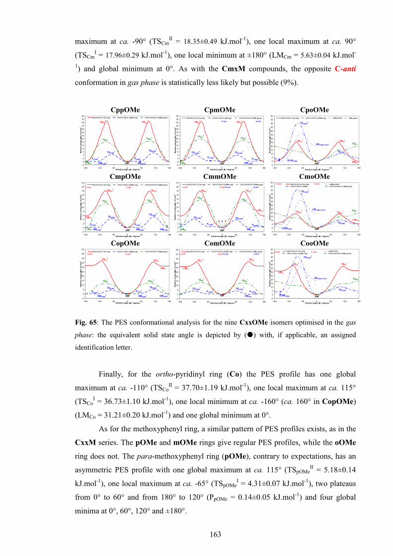
163
maximum at ca. -90° (TSCmII = 18.35±0.49 kJ.mol-1), one local maximum at ca. 90°
(TSCmI = 17.96±0.29 kJ.mol-1), one local minimum at ±180° (LMCm = 5.63±0.04 kJ.mol-
1) and global minimum at 0°. As with the CmxM compounds, the opposite C-anti
conformation in gas phase is statistically less likely but possible (9%).
CppOMe
-2
0
2
4
6
8
10
12
14
16
18
20
22
24
26
28
-180 -120 -60 0 60 120 180Dihedral angle (θθθθ ) / degrees
Relative energy (
∆∆ ∆∆E) / kJ.m
ol-1
C26-C21-N1-C1 (Cp ring) C16-C11-O2-C1 (pOMe ring) C15-C14-O14-C17 (OMe group)
TSpOMeI
PpOMeI
GM0GMpOMe
I'GMpOMe
I
TSpOMeII
PpOMeI'
TSCpI
TSCpI'
TSMeI TSMe
II
LMMe
CpmOMe
-2
0
2
4
6
8
10
12
14
16
18
20
22
24
26
28
-180 -120 -60 0 60 120 180Dihedral angle (θθθθ ) / degrees
Relative energy (
∆∆ ∆∆E) / kJ.m
ol-1
C26-C21-N1-C1 (Cp ring) C16-C11-O2-C1 (mM ring) C15-C14-O14-C17 (OMe group)
TSmOMeII
PmOMeI
GM0 GMmOMe
TSmOMeI
PmOMeI'
TSCpI
TSCpI' O-syn O-anti
TSMeII
TSMeI
LMMe
CpoOMe
-5
0
5
10
15
20
25
30
35
40
45
50
55
60
-180 -120 -60 0 60 120 180Dihedral angle (θθθθ ) / degrees
Relative energy (
∆∆ ∆∆E) / kJ.m
ol-1
C26-C21-N1-C1 (Cp ring) C16-C11-O2-C1 (oOMe ring) oOMe-COCO OMe group
GM0 GMCp
G/LMoOMe
TSoOMeII
TSoOMeI
TSCpI
TSCpI'
LMoOMe-COCOTSMe
CmpOMe
-2
0
2
4
6
8
10
12
14
16
18
20
22
-180 -120 -60 0 60 120 180Dihedral angle (θθθθ ) / degrees
Relative energy (
∆∆ ∆∆E) / kJ.m
ol-1
C26-C21-N1-C1 (Cm ring) C16-C11-O2-C1 (pOMe ring) C15-C14-O14-C17 (OMe group)
GMpOMeI''
TSpOMeI
GM0
TSpOMeII
PpOMeI'
TSCmI
TSCmII
GMpOMeI
C-anti C-syn
GMpOMeI'
LMCm
PpOMeI
TSMeI TSMe
II
LMMe
CmmOMe
-2
0
2
4
6
8
10
12
14
16
18
20
22
-180 -120 -60 0 60 120 180Dihedral angle (θθθθ ) / degrees
Relative energy (
∆∆ ∆∆E) / kJ.m
ol-1
C26-C21-N1-C1 (Cm ring) C16-C11-O2-C1 (mOMe ring) C15-C14-O14-C17 (OMe group)
TSmOMeITSmOMe
II
GM0
PmOMeI
GMmOMe
TSCmII
TSCmI
PmOMeI'
C-anti C -syn /O-syn O-anti
LMCm
TSMeITSMe
II
LMMe
A AB
B
CmoOMe
-5
0
5
10
15
20
25
30
35
40
45
50
55
60
-180 -120 -60 0 60 120 180Dihedral angle (θθθθ ) / degrees
Relative energy (
∆∆ ∆∆E) / kJ.m
ol-1
C26-C21-N1-C1 (Cm ring) oOMe-COCO
C16-C11-O2-C1 (oOMe) C15-C14-O14-C17 (OMe group)
TSoOMeII
GM0L/GMoOMe
TSoOMeI
TSCmII
TSCmI
C-anti C -syn
LMCm
LMoOMe-COCO TSMe
CopOMe
-5
0
5
10
15
20
25
30
35
40
45
50
-180 -120 -60 0 60 120 180Dihedral angle (θθθθ ) / degrees
Relative energy (
∆∆ ∆∆E) / kJ.m
ol-1
C26-C21-N1-C1 (Co ring) C16-C11-O2-C1 (pOMe ring) C15-C14-O14-C17 (OMe group)
PpOMeI'
TSpOMeII
GM0
GMpOMeI''
PpOMeI
TSpOMeI
TSCoITSCo
II
GMpOMeI
C-anti C-syn
GMpOMeI'
LMCoI
TSMeI
TSMeII
ComOMe
-5
0
5
10
15
20
25
30
35
40
45
50
-180 -120 -60 0 60 120 180Dihedral angle (θθθθ ) / degrees
Relative energy (
∆∆ ∆∆E) / kJ.m
ol-1
C26-C21-N1-C1 (Co ring) C16-C11-O2-C1 (mOMe ring) C15-C14-O14-C17 (OMe group)
TSmOMeI
TSmOMeI'
GM0
GMmM
PmOMeI'
TSCoI
TSCoII
C-anti C-syn /O-syn O-anti
TSMeII
TSMeI
PmOMeI
LMCo
CooOMe
-5
0
5
10
15
20
25
30
35
40
45
50
55
60
-180 -120 -60 0 60 120 180Dihedral angle (θθθθ ) / degrees
Relative energy (
∆∆ ∆∆E) / kJ.m
ol-1
C26-C21-N1-C1 (Co ring) oOMe-COCO
C16-C11-O2-C1 (oOMe ring) C15-C14-O14-C17 (OMe group)
TSoOMeII
GM0L/GMoOMe
TSoOMeI
TSCoI
TSCoII
C-anti C -syn
LMCo
LMoOMe-COCO TSMeI
Fig. 65: The PES conformational analysis for the nine CxxOMe isomers optimised in the gas
phase: the equivalent solid state angle is depicted by (�) with, if applicable, an assigned
identification letter.
Finally, for the ortho-pyridinyl ring (Co) the PES profile has one global
maximum at ca. -110° (TSCoII = 37.70±1.19 kJ.mol-1), one local maximum at ca. 115°
(TSCoI = 36.73±1.10 kJ.mol-1), one local minimum at ca. -160° (ca. 160° in CopOMe)
(LMCo = 31.21±0.20 kJ.mol-1) and one global minimum at 0°.
As for the methoxyphenyl ring, a similar pattern of PES profiles exists, as in the
CxxM series. The pOMe and mOMe rings give regular PES profiles, while the oOMe
ring does not. The para-methoxyphenyl ring (pOMe), contrary to expectations, has an
asymmetric PES profile with one global maximum at ca. 115° (TSpOMeII = 5.18±0.14
kJ.mol-1), one local maximum at ca. -65° (TSpOMeI = 4.31±0.07 kJ.mol-1), two plateaus
from 0° to 60° and from 180° to 120° (PpOMe = 0.14±0.05 kJ.mol-1) and four global
minima at 0°, 60°, 120° and ±180°.

164
A similar PES profile is found in the meta-methoxyphenyl ring (mOMe): a
global maximum at ca. 60° (TSmOMeII = 4.05±0.17 kJ.mol-1), local maximum at 120°
(TSmOMeI = 3.87±0.07 kJ.mol-1), two plateaus from -60° to -20° and from 140° to 180°
(PmOMeI = 0.45±0.04 kJ.mol-1) and two local minima at 0° and 120°.
The plateaus are very low, flat barriers that allow free rotation of the pOMe and
mOMe rings in these regions. Furthermore, low rotational barriers allow full rotation of
the pOMe and mOMe rings and therefore exceptional flexibility. Mild asymmetry of
the pOMe profile reflects the asymmetric position of the methoxy group. The global
minimum of the mOMe ring is in an O-syn conformation, but high flexibility and a
very low energy difference (0.45±0.04 kJ.mol-1) into the opposite O-anti conformation
makes both conformations nearly equivalent (55:45).
Conformational analysis of the oOMe ring resembles the oM ring in the CxxM
isomer grid. If the COCO ring is not constrained the conformational analysis scan ends
up in a meta-stable form due to the collision of carbonyl and methoxy moieties and
consequent deviation of the COCO dihedral angle. The relaxed PES profile of the
oOMe ring with COCO angle deviation is shown as a dashed light blue curve (oOMe-
COCO ring). It has one global maximum at ca. -70° (TSoFII = 36.75±0.34 kJ.mol-1), one
local maximum at ca. 105° (TSoFI = 9.89±0.11 kJ.mol-1) and two global minima at 0 and
-145°. Due to the displacement of the COCO dihedral angle into its unlikely local
minimum, the PES curve does not end at the starting global minimum, but at an
implausible local minimum at 0° (LMoF-COCO = 19.48±0.67 kJ.mol-1).
However, if the COCO ring is kept constrained (“frozen”), only the oOMe ring
rotates (even forcible), the resulting PES profile is a deep blue dashed curve (oOMe
ring). Similar to the relaxed case, it has one global maximum at ca. -80° (TSoFII =
50.58±0.08 kJ.mol-1), one local maximum at ca. 100° (TSoFI = 10.56±0.19 kJ.mol-1),
one local minimum at ca. -160° (LMoFII = 3.38±0.73 kJ.mol-1) and one global minimum
at 0°. In contrast to the PES profile, it successfully managed to loop to the starting
global minimum. The high rotational barrier upon steric clash of the carbonyl and
methoxy groups suggests that in reality (at room temperature) this rotation is not
probable; rotation of the COCO dihedral angle into an unlikely local minimum is not
probable either. However, in most of the dihedral angle regions two PES profiles
overlap, except in the region from 180° to 120° where the constrained PES profile has a
local minimum (LMoFII = 3.38±0.73 kJ.mol-1), while the relaxed PES profile has a
global minimum. Both curves are approximations since the forcible rotation as seen in
the mechanism of conformational analysis is not probable under real conditions.

165
Instead, a real PES curve would be a combination of both; from 0° to 180° and from -
180° to -145° the relaxed would dominate and from -145° to 0° the constrained case
would dominate.
The additional dihedral angle in CxxOMe compounds is the rotation of the
methoxy group about the phenC-C-O-CH3 angle, or Me (ω) dihedral angle. As expected,
the PES profile depends on the methoxy group position. If para-substituted (pOMe) it
is nearly symmetric with one global maximum at ca. 90° (TSMeII = 12.29±0.23 kJ.mol-1)
and one local maximum at ca. -90° (TSMeI = 11.62±0.13 kJ.mol-1). The global minimum
is at 0°, but the expected second global minimum at ±180° is due to the deviation of the
O-ring from planarity (66.69±0.68°), a local minimum (LMMe = 0.03 kJ.mol-1).
Nevertheless, the energy difference value (0.03 kJ.mol-1) is negligible and in reality
both conformations are equivalent. The rotational barriers are relatively high and wide,
while the potential well is narrow. This form of PES profile suggests low flexibility and
lower interchange rate, but both conformations are equivalent. In meta-substituted
isomers (CxmOMe), the PES profile is very similar as in the pOMe rings, but more
asymmetric with higher barriers; the global maximum is at ca. -90° (TSMeI = 12.81±0.11
kJ.mol-1), the local maximum is at ca. 90° (TSMeII = 13.47±0.28 kJ.mol-1) and a global
minimum is at 0°. The local minimum is at ca. ±180° (LMMe = 0.27±0.03 kJ.mol-1) and
both the Me-anti and the Me-syn conformations are plausible (53:47). Due to the steric
repulsion, the ortho-substituted (oOMe) rings have differently shaped PES profiles,
with only one maximum at ca. ±180° (TSMeI = 18.84±0.96 kJ.mol-1) and one global
minimum at 0°. The rotational barrier is lower, but the slope is uneven. Therefore, the
oOMe ring can exist only in the Me-anti conformation.
The COCO dihedral angle PES profile is symmetric and similar in the CxpOMe
and CxmOMe isomers with two global maxima at ca. ±105° (TSCOCOI = 27.32±1.54
kJ.mol-1), one local minimum at ±180° (LMCOCOI = 18.13±0.42 kJ.mol-1) and a global
minimum at 0°.
In the CxoOMe isomers the conformational analysis scan ends with
neighbouring oOMe dihedral angles deviating from their global minima (deep yellow
dashed curves). However, if the oOMe dihedral angle is kept constrained the result is a
different PES profile (brown dashed curves) with global maximum at ca. -100°
(TSCOCOII = 45.64±0.73 kJ.mol-1), local maximum at ca. 90° (TSCOCO
I = 31.70±1.00
kJ.mol-1), local minimum at ca. ±180° (LMCOCOI = 19.38±0.63 kJ.mol-1) and a plateau at
ca. 145° (PCOCO = 26.88±0.76 kJ.mol-1). Regardless of the actual shape, the high

166
rotational barriers and local minimum do not allow the opposite conformation to be
plausible, while the wide potential well suggests a certain level of molecular flexibility.
Finally, the OCNC dihedral angles are approximately the same in all CxxOMe
compounds with two global maxima at ca. -70° and 110° (TSOCNC = 68.96±2.09 kJ.mol-
1), one local minimum at ±180° (LMOCNC = 11.62±0.64 kJ.mol-1) and a global minimum
at 0°. A very high PES profile suggests the improbability of a conformational change
although, as with the COCO ring, a certain level of flexibility is envisaged.
7.3 Comparisons of the solid state and modelling data
Comparison of the CxxOMe isomer structures between the eight available
crystal structures and calculations is made by marking (as �) torsion angle differences
(∆θ) between the available experimental and theoretical structures on the corresponding
gas phase PES diagrams (Fig. 65). For the CmmOMe isomer the disordered parts of
the molecule are labelled as A or B.
In general, the C-ring conformations (C-syn) and pyridinyl dihedral angles of
the solid state molecular structures match those of modelled structures with deviations
of no more than ±10°. Usually, the C-syn conformation in the Cm rings is not favorable
for the formation of C(5) hydrogen bonded chains, opposite to the C-anti conformation
that exposes pyridinyl N23 atoms to the N1-H1 moieties and allow formation of
hydrogen bonded chains. However, aggregation of the CmpOMe isomer (and the
isomorphous CmpM) in the P212121 space group allows formation of N1-H1···N23
even if the Cm rings are in the C-syn conformation. On the other hand, formation of the
CmmOMe trimer is another unique example of how aggregation can be accomplished
without a conformational change. A similar case is seen in the NmpF tetramers and
NmpM catemers (Chaper I, Section 2.2.5.3) where pyridinyl rings are in the C-syn
conformation too. However, it is quite surprising that trimer formation was not found in
any of the benzamide/pyridinecarboxamide isomer grids, where formation of C(5)
chains with C-anti conformers are preferred, except for the NmpF tetramers and
NmpM catemers (Chapter I, Section 2.2.5.3).
The mOMe dihedral angle has flexibility, allowing free rotation. However, the
methoxyphenyl rings in the solid state molecular structures generally correspond with
the modelled versions in six out of eight cases with little or no deviations from the
global minima. The exception is the CpmOMe isomer, where the solid state dihedral
angle lies on the PmOMeI’ plateau, a position that allows formation of five secondary

167
interactions (Section 7.1.1). In the solid state structure of ComOMe, the mOMe ring is
orthogonal to the pyridinyl ring, on the cusp of C-syn conformation. This position is
essential for the formation of secondary C12-H12···O1e (e = 1+x,y,z), C17-
H17A···Cg2i [Cg2 = (C11…C16)] and C14-H14···O3c (c = 2-x,1-y,-z) interactions
between dimers, that are crucial for aggregation in the solid state (Fig. 63).
Finally, for the CmmOMe trimer 50% of molecules are in an O-syn
conformation (A part) while the remaining 50% are O-anti (B part). The B part is on the
PmOMeI plateau, however, due to the flexibility of the O-ring and very low energy
difference (0.45±0.04 kJ.mol-1), the B part (O-anti) is effectively equivalent to A (O-
syn). The occurrence of both conformations is justified by the importance of the
secondary interactions that are possible only if both conformations are available: the
C12-H12···O1Bd [d = 1-x+y,y,z-1/2] hydrogen bonding as well as the C17-
H17C···O1Ae [e = 2/3-x+y,4/3-x,-2/3+z] and C25B-H25B···O3f [f = 1/3+x,2/3+x-
y,1/6+z] interactions are essential for the aggregation of trimers into the observed
crystal structure.
In five out of eight solid state structures the conformations of the methoxy group
(Me) do not overlap with the preferred conformation in the optimised structures.
However, for the mOMe ring, the low energy differences (0.03-0.27 kJ.mol-1) in both
CxpOMe and CxmOMe isomers effectively equalise the plausibility of both
conformations. On the other hand, deviations from the minima are rarely higher than 5°
(10° in the CmpOMe isomer). In each isomer a particular interaction drives the ω
dihedral angle conformation into the Me-syn or Me-anti conformation.
The COCO and OCNC dihedral angles in the solid state match with the
equivalent in optimised structures without or with an offset that does not exceed 15°.
The high rotational barriers, especially for the OCNC dihedral angles, as well as high
local minima, prevent conformational change.
8. CxxX compounds
8.1. Molecular and crystal structure data
The main challenge with the halo-carbamate compounds was their inability to
produce quality single crystals. Even after numerous attempts, using various solvents
and blends of solvents, only 10 out of 24 synthesised halophenyl-N-pyridinyl-
carbamates (CxxF, CxxCl and CxxBr isomer grids) gave single crystals suitable for

168
SXRD. Therefore, structural features of all 10 determined halo-carbamate crystals
structures will be described together as CxxX (X = F, Cl, Br) compounds.
The main structural characteristic of the CxxX compounds is the isomorphology
of analogous isomers. The CmpX compounds are found in the Pc space group, CmmX
in Cc and CopX (except the CopBr isomer) in the P ̅1 space group. Tables 34 and 35
summarise the basic crystallographic data and structural features.
8.1.1 CxxF isomer grid
Three compounds (CmpF, CmmF and CopF) among a total of seven isomers
gave single crystals.
CmpF molecular and crystal structure
The CmpF crystals were grown from CHCl3. The principal aggregation in the
CmpF crystal structure is accomplished by two alternating N1-H1···N23 hydrogen
bonds (Fig. 66). The two molecules in the asymmetric unit (A and B) are connected into
a pair (A→B) via N1A-H1A···N23B [N1A···N23B = 2.996(3) Å] hydrogen bonds,
augmented with flanking C22B-H22B···O2A [C22B···O2A = 3.333(3) Å] interactions.
The AB pairs are connected along the c-axis direction into an undulating C(5) chain
(···AB→AB···) parallel with the (010) plane by N1B-H1B···N23Aa [N1B···N23Aa =
2.938(3) Å, a = x, -y+1, z-1/2] hydrogen bonds (Fig. 66). In order to allow formation of
the C(5) chains the pyridinyl rings are in a C-anti conformation. This conformation is
already observed in similar C(5) chains in the benzamides (NmmF, Fmm, Chapter I).
Table 34: Selected crystallographic data for the ten CxxX compounds†
CxxX Space group Z’ Volume (Å3) R[F2 > 2σ(F
2)], wR(F
2)
CmpF Pc 2 1060.50(5) 0.039, 0.097 CmmF Cc 1 1052.85(15) 0.052, 0.122 CopF P̅1 1 526.52(14) 0.046, 0.114
CpmCl P21 1 548.85(5) 0.041, 0.076 CmpCl Pc 2 1141.25(18) 0.041, 0.103 CmmCl Cc 1 1108.7(3) 0.094, 0.248 CopCl P̅1 1 559.6(3) 0.092, 0.241
CmpBr Pc 2 1172.65(6) 0.050, 0.091 CmoBr P21/c 1 1269.90(7) 0.046, 0.106 CopBra P21/n 1 1147.2(9) 0.095, 0.260 † Complete crystallographic, refinement and structural details for the ten CxxX isomers are
listed in the ESI II (Section 2.3). a Obtained with Cu Kα radiation.

169
Table 35: Relevant structural features (Å, °) in ten CxxX isomersa
CxxX C6/C5N C6/carbamate C5N/carbamate N…N/Ob Packing
49.88(7) 60.01(7) 12.89(14) 2.996(3) CmpF
31.61(9) 53.26(8) 45.23(8) 2.938(3) C(5) chains
CmmF 29.77(12) 51.44(12) 37.18(13) 2.951(4) C(5) chains CopF 53.34(6) 57.93(6) 4.60(13) 2.997(3) R2
2(8) dimers CpmCl 40.71(9) 54.04(9) 13.68(16) 2.949(4) C(6) chains
31.29(10) 52.94(10) 44.15(11) 2.929(4) CmpCl
49.77(7) 60.37(9) 13.09(19) 2.985(4) C(5) chains
CmmCl 28.26(28) 49.79(26) 37.11(3) 2.937(11) C(5) chains CopCl 54.32(15) 58.36(14) 4.38(32) 2.994(7) R2
2(8) dimers 50.83(14) 58.39(15) 12.43(26) 2.986(7)
CmpBr 31.86(19) 53.20(18) 43.64(17) 2.925(7)
C(5) chains
CmoBr 65.76(10) 87.10(9) 26.99(15) 2.832(4)c
2.837(4)d R
44(14) dimers
CopBr 55.34(23) 59.73(26) 6.35(55) 2.979(11) R22(8) dimers
a Full structural details are provided in the ESI II (Section 2.3). b The carbamateN···Npyridine interaction distances, c The carbamateN···Owater interaction distances, d The waterO···Npyridine interaction distances.
The undulating 1-D chains are linked into a 2-D sheet parallel with the (100)
plane via several bonds and interactions. The strongest among them is the C16A-
H16A···O1Bc [C16···O1Bc = 3.203(3) Å, c = x, -1+y, z] hydrogen bond, linking A and
B molecules from adjacent chains. Other notable interactions that stabilise the 2-D
sheet, are C16B-H16B···O1Ad [C16B···O1Ad = 3.314(4) Å, d = x, -y+2, z-1/2] and
C12A-H12A···O1Ae [C12A···O1Ae = 3.360(3) Å, e = x, 1+y, z]. Finally, there are three
weak π···π stacking interactions in the sheet: C12A···C16Ae [3.382(4) Å],
C13A···C15Ae [3.398(4) Å] and C14B···C13Be [3.391(5) Å]. The sheets are connected
by weak C26B-H26B···F14Bf [C26B···F14Bf = 3.323(3) Å, f = -1+x, y, z] contacts
linking the 2-D sheets into a 3-D crystal structure.
Fig. 66: Hydrogen bonding and aggregation in the CmpF isomer, forming AB pairs and ABAB
chains (a, b = x,1-y,-½+z)

170
As already mentioned, the pyridinyl rings (C-ring, C5N) of both molecules are in
a C-anti conformation. Geometry differences among the A and B molecules are not
significant; the most notable is the difference between the interplanar angles (18.27°)
and the C5N/carbamate plane (32.34°).
CmmF molecular and crystal structure
The CmmF isomer aggregates in the Cc space group (No. 9) with Z’ = 1. Single
crystals were grown from CHCl3.
Fig. 67: Hydrogen bonding in the CmmF isomer (a = x,-y,-½+z; b = x,1-y, ½+z)
Despite being in a different space group and having a different Z’, there are
substantial similarities between CmpF and CmmF and their intermolecular
interactions. The primary interaction in CmmF is the N1-H1···N23c [N1···N23c =
2.951(4) Å, c = x,-y,1/2+z] hydrogen bond, linking molecules along the c-axis direction
into a C(5) chain parallel with the (010) plane (Fig. 67). The N1-H1···N23 hydrogen
bond is aided with flanking C22-H22···O2a [C22-H22···O2a = 3.371(4) Å, a = x,-y,-
1/2+z] interactions. The C(5) chains are interconnected into a 2-D sheet parallel with
the (100) plane by C16-H16···O1b [C16···O1b = 3.253(5) Å, b = x,1-y,1/2+z] hydrogen
bonds. These bonds are aided by weak π-π contacts C14···C13d [3.395(7) Å, d = x, 1+y,
z]. Finally, the sheets are interconnected through weak C25-H25···F13e [C25···F13e =
3.301(5) Å, e = 1/2+x,1/2-y,1/2+z] contacts.
The geometry of the CmmF molecule resembles the geometry of the B molecule
of the CmpF isomer. The interplanar angle of C6/C5N is 29.77(12)°, while the
C6/carbamate angle is 51.44(12)° and C5N/carbamate angle is 37.18(13)°. As expected,
the pyridinyl ring (C5N, C-ring) is in the C-anti conformation, mandatory for the

171
formation of C(5) hydrogen bonded chains, and the meta-fluorophenyl ring is in the F-
anti conformation.
CopF molecular and crystal structure
CopF forms dimers similar to the CoxM and CoxOMe isomers, about inversion
centres via N1-H1···N22a [N1-H1···N22a = 2.997(3) Å, a = -x,1-y,2-z] hydrogen bonds
producing R22(8) hydrogen bonded rings. The dimer formation is augmented by flanking
C23-H23···O2a [C23···O2a = 3.271(3) Å] interactions (Fig. 68).
Fig. 68: Hydrogen bonding in CopF (a = -x,1-y,2-z; b = -x,1-y,1-z; c = x,y,-1+z)
Apart from the interactions involved in dimerisation, there is only one additional
intermolecular interaction. A weak C13-H13···O1b (C13···O1b = 3.444 Å, b = -x, 1-y,
1-z) interaction interconnects dimers along the c-axis direction into a 1-D chain (Fig.
68). As a result, CopF crystallises as very fine needles (single crystals were grown from
CHCl3/acetone mixtures). As a comparison, the CopOMe (Section 7.1.3) isomer forms
similar dimers, but has additional interactions between a carbonyl moiety, methoxy
group and H24 forming a 2-D sheet.
The geometry parameters of the CopF molecule are typical for a CopR isomer
(Table 35): a pyridinyl ring nearly co-planar with the carbamate plane [4.60(13)°], and a
rotated para-fluorophenyl ring [57.93(6)°].

172
8.1.2 CxxCl isomer grid
CpmCl molecular and crystal structure
CpmCl is the only CpxX compound that gave quality single crystals; the
crystallisation solvent was CHCl3. It crystallises in the P21 space group Z’ = 1.
Fig. 69: Hydrogen bonding in the CpmCl isomer (a = 1-x,-½+y,-z; b = 1+x,y,-1+z; c = 1-
x,½+y,-z; d = -x,½+y,1-z; e = -1+x,y,1+z; f = -x,-½+y,1-z)
The structure of the CpmCl isomer is a 2-D sheet (Fig. 69) and relies on two
interactions only. The main interaction is N1-H1···N24d [N1···N24d = 2.949(4) Å, d = -
x,½+y,1-z] hydrogen bonding, connecting the molecules along the b-axis direction into
a “fish bone” C(6) chain parallel with the (101) plane. Parallel oriented C(6) chains are
interconnected via C14-H14···O1a [C14···O1a = 3.318(4) Å, a = 1-x,1/2+y,-z]
interactions into a 2-D sheet parallel with the (101) plane. The 2-D sheets stack in the
(010) direction. It is interesting to note that chlorine atoms, surrounded by hydrogen
atoms and lined up along the (010) direction, do not engage in any interaction.
The conformation of the meta-chlorophenyl ring (Cl-ring) is Cl-anti. The
CpmCl molecule has a typical phenyl-N-pyridinyl-carbamate geometry (Table 35); the
pyridinyl ring and the carbamate planes are nearly planar [13.68(16)°] while the meta-
chlorophenyl ring deviates from planarity by [54.04(9)°].

173
CmpCl molecular and crystal structure
The CmpCl isomer (Fig. 70) is isomorphous with its fluorine analogue CmpF.
It was grown from CHCl3/toluene solvent mixtures. However, due to the chlorine atom,
slight differences in volume and intermolecular interactions exist. The CmpCl volume
is 1141.25(18) Å3 and significantly larger than CmpF [1060.50(5) Å3].
The two principal interactions in the CmpCl isomer are the N1-H1···N23 and
C16-H16···O1 hydrogen bonds. Two molecules in the asymmetric unit, A and B, are
linked into a pair (B→A) via N1B-H1B···N23A [N1B···N23A = 2.985(4) Å] hydrogen
bonds. The interaction is stabilised with flanking C22B-H22B···O2A [C22B···O2A =
3.333(4) Å] interactions.
Fig. 70: Hydrogen bonding in CmpCl, as BA pairs and BABA chains (a, b = x,-1-y,½+z)
As similar to the CmpF isomer, the BA pairs are linked along the c-axis
direction into a wavy C(5) column (···BA→BA···) parallel with the (010) plane via
N1A-H1A···N23Ba [N1A···N23Ba = 2.929(4) Å, a = x,-1-y,1/2+z] hydrogen bonding.
The (···BABA···) columns are interconnected along the b-axis direction into a 2-D sheet
parallel with the (100) plane via secondary C16A-H16A···O1Bc [C16A···O1Bc =
3.306(4) Å, c = x,-y,1/2+z] and C16B-H16B···O1Ad [C16B···O1Ad = 3.198(4) Å, d = x,
-1+y, z] hydrogen bonds, aided by an additional C12B-H12B···O1Be [C12B···O1Be =
3.385(4) Å, e = x,1+y,z] interaction. As opposite to the CmpF isomer, no significant
π···π stacking was found in the CmpCl crystal structure; the chlorine atom does not
engage in any interaction.
As in all CmxR carbamates, the pyridinyl rings (C-ring, C5N) have to be in a C-
anti conformation as it is the condition for aggregation via N1-H1···N23 hydrogen

174
bonds into C(5) chains. Geometries of the A and B molecules in the CmpCl isomer are
almost identical to those in B and A molecules of the fluorine analogue CmpF.
CmmCl molecular and crystal structure
The CmmCl isomer in the Cc space group with Z’ = 1 is isomorphous with its
fluorine analogue CmmF. As for CmpCl/CmpF, there are some minor differences
between the CmmCl and CmmF crystal structures. Single crystals were grown from a
mixture of CHCl3, acetone and toluene.
The main backbone of the CmmCl crystal structure is the N1-H1···N23a
[N1···N23a = 2.937(10) Å, a = x, -y, -1/2+z] hydrogen bonding that connects molecules
along the c-axis direction into a C(5) column parallel with the (100) plane (Fig. 71). The
hydrogen bonds are augmented by C22-H22···O2b [C22···O2b = 3.360(11) Å, b = x, -y,
1/2+z] interactions. Next, the C(5) columns are interconnected along the b-axis
direction via C16-H16···O1b [C16···O1b = 3.216(12) Å, b = x,1-y,-1/2+z] interactions
into 2-D sheets parallel with the (100) plane (Fig. 71). The sheets are further linked
along the (10 ̅1) direction via C25-H25···Cl13c [C25···Cl13c = 3.620(11) Å, c = -1/2+x,
1/2-y, -1/2+z] interactions. No additional π···π stacking was noted in the crystal
structure. The geometrical parameters of the CmmCl isomer match with those of the
analogous CmmF isomer (Table 35). As expected, the pyridinyl ring (C5N, C-ring) is in
the C-anti conformation and the meta-chlorophenyl ring (mCl) is Cl-anti.
Fig.71: Hydrogen bonding in CmmCl (a = x,-y,-½+z; b = x,1-y,-½+z)

175
CopCl molecular and crystal structure
The CopCl crystal structure is isomorphous with CopF. As in other cases, both
similarities and differences regarding the intermolecular interactions exist. Needle-like
single crystals were grown from a mixture of CHCl3 and acetone.
The main structural feature of all CoxR compounds is the formation of dimers
through strong N1-H1···N22 hydrogen bonds and CopCl is not an exception. The
R2
2(8) hydrogen bonded rings are formed about inversion centres via double N1-
H1···N22c [N1-H1···N22c = 2.994(7) Å, c = 1-x,1-y,-z] hydrogen bonds and augmented
by C23-H23···O2c [C23···O2c = 3.273(8) Å] interactions (Fig. 72). Furthermore, dimers
are linked along the c-axis direction into a column parallel with the (010) plane through
strong C13-H13···O1b [C13···O1b = 3.425(8) Å, b = 1-x,1-y,1-z] interactions (Fig. 72).
As opposite to the minimalistic aggregation in CopF, there are two additional but weak
contacts. The first one is a relatively weak C12-H12···O1d [C12···O1d = 3.382(7) Å, d =
1+x,y,z] contact that connects columns along the a-axis direction into a 2-D sheet
parallel with the (010) plane. The second contact is a weak C15···C15e [C15···C15e =
3.459(10) Å, e = 1-x,2-y,1-z] interaction, and it loosely links 2-D sheets along the (01 ̅1)
plane into a 3-D crystal structure. The geometric parameters of the CopCl isomer match
those of the isomorphous CopF.
Fig. 72: Hydrogen bonding in the CopCl isomer (a = x,y,1+z, b = 1-x,1-y,1-z; c = 1-x,1-y,-z)
8.1.3 CxxBr isomer grid
Similar to the CxxF isomer grid, only three compounds, CmpBr, CmoBr and
CopBr out of the eight CxxBr isomers gave suitable single crystals. The rest of the
CxxBr compounds are less crystalline products; the crystal growth in various solvents
gave poor results or decomposition.

176
CmpBr molecular and crystal structure
The CmpBr isomer (Fig. 73) is isomorphous with CmpF and CmpCl. The
principal interaction in the CmpBr crystal structure is, similar to its chloro and fluoro
analogues, the N1-H1···N23 interaction. Two molecules of CmpBr (A and B) are
joined into a pair (A→B) via N1A-H1A···N23B [N1A···N23B = 2.986(7) Å] hydrogen
bonding. The pairing is augmented by the C22B-H22B···O2A [C22B···O2A = 3.312(7)
Å] interaction. The pairs (AB) are connected (···AB→AB···) along the c-axis direction
into an undulating C(5) chain (···ABAB···) through N1B-H1B···N23Aa [N1B···N23Aa
= 2.925(7) Å, a = x,1-y,-1/2+z] hydrogen bonds.
Fig. 73: Hydrogen bonding in CmpCl, as AB pairs and ABAB chains (a, b = x,1-y,-½+z)
As for the chloro- and fluoro- analogues, the chains are interconnected along the
b-axis direction into 2-D sheets parallel with the (100) plane through C16A-
H16A···O1Bc [C16A···O1Bc = 3.199(8) Å, c = x,1+y,z] and C16B-H16B···O1Ad
[C16B···O1Ad = 3.297(8) Å, d = x,-y,-1/2+z] hydrogen bonds. The sheet is stabilised by
C12A-H12A···O1Ae [C12A···O1Ae = 3.395(7) Å, e = x,-1+y,z] contacts. No interaction
involving the bromine atom was found. The geometries of the A and B molecules of the
CmpBr isomer correspond with those of the analogous CmpF isomer.
CmoBr molecular and crystal structure
Along with the CmoM isomer, the CmoBr compound is an isomer isolated as a
monohydrate (CmoBr:H2O) and the crystal structure is isomorphous with the
CmoM:H2O crystal structure.

177
As with the CmoM:H2O complex, two molecules of both water and CmoBr
aggregate into a hydrogen bonded complex that forms R44(14) hydrogen bonded rings.
The molecules of water act as linkers between two CmoBr molecules. The key
interactions in the formation of the complex are N1-H1···O1W [N1···O1W = 2.832(4)
Å] and O1W-H2W···N23c [O1W···N23c = 2.837(4) Å, c = 1-x,2-y,-z] hydrogen bonds
bridging two molecules of CmoBr via two H2O molecules (Fig. 74).
Fig. 74: The hydrogen bonding in the CmoBr monohydrate (a = x,3/2-y,-½+z, b, c = 1-x,2-y,-z).
Furthermore, the R4
4(14) hydrogen bonded complexes are directly connected
into a 2-D sheet parallel with the (100) plane via O1W-H1W···O1d [O1W···O1d =
2.925(4) Å, d = x,3/2-y,1/2+z] hydrogen bonds. In total, there are three hydrogen bonds
interconnecting molecules of CmoBr and H2O into a 2-D sheet. The sheet is stabilised
by two interactions. The first is the C26-H26···O1e [C26···O1e = 3.384(3) Å, e = 1-x,1-
y,-z] interaction and second is the C-Br···π(arene) interaction, C12-Br1···C11a
[Br1···C11a = 3.533(3) Å, a = x,3/2-y,-1/2+z]. The geometry of the CmoBr molecules
agrees with the CmoM geometry. The conformation of the C-ring is C-syn.
CopBr molecular and crystal structure
Contrary to what would be expected, the CopBr crystal structure (Fig. 75) is not
isomorphous with the related fluorine (CopF) and chlorine (CopCl) isomers. It
crystallises in P21/n with Z’ = 1 and is therefore more similar to CopM and CopOMe.
Crystals were grown from tetrahydrofuran (THF).

178
However, as with all CoxR compounds, the CopBr molecules form dimers
about inversion centres via double N1-H1···N22a [N1···N22a = 2.979(11) Å, a = 1-x,-
y,1-z] hydrogen bonds forming R22(8) hydrogen bonded rings. The dimer is stabilised
by auxiliary C23-H23···O1a [C23···O1a = 3.307(13) Å] interactions. Without forming
one-dimensional chains, the dimers are directly interconnected into a 2-D sheet parallel
with the (̅101) plane by C15-H15···O1c [C15…O1c = 3.301(13) Å, c = 1/2-x,-1/2+y,1/2-
z] hydrogen bonds. The sheets are interconnected into a crystal structure through weak
C-H···π(arene) interaction C13-H13···C13d (H13···C1d = 2.80 Å, d = 3/2-x,1/2+y,1/2-
z). Bromine atoms do not engage in intermolecular interactions.
With nearly co-planar pyridinyl ring and carbamate planes [6.35(55)°] and
twisted para-bromophenyl ring [59.73(26)°], the CopBr has the typical “carbamate”
molecular geometry.
Fig. 75: Hydrogen bonding in CopBr (a = 1-x,-y,1-z, b = -½+x,-½-y,-½+z, c = ½-x,- ½+y, ½-z)
8.2. Ab initio calculations and modelling data
8.2.1. Structure optimisation
Tables 36a-c summarise the geometry parameters for the 27 optimised CxxX
isomers (CxxF, CxxCl and CxxBr isomer grids), including α (C-ring), β (F-/Cl-/Br-
ring), γ (COCO) and δ (OCNC) dihedral angles, as well as the relative deviation of the
F-/Cl-/Br-ring from planarity (β*).
Analysis of the molecular structures uncovers similarities and subtle differences.
However, there is no significant difference between the analogous isomers, apart from
minor changes in the β and γ dihedral angles. Therefore, aspects of the optimised
geometries will be discussed for all of the CxxX isomers together. With regards to the
geometric parameters, the halo-carbamate isomers can be divided into 3 groups; CxpX

179
and CxmX isomers and CxoX isomers, as for the carbamate isomer grids (CxxM and
CxxOMe). The first group has its para-/meta-halophenyl rings rotated by ~60°, and in
the CxoX isomers the ortho-halophenyl rings are close to orthogonal relative to the
pyridinyl rings and the carbamate planes. Nevertheless, all isomers have planar C-rings
(α) and OCNC (δ) dihedral angles, -0.42±0.52° and 0.17±0.49°, respectively.
Conformations of the Cm and Co rings are always C-syn.
The COCO ring is planar in all of the CxpX and CxmX isomers (-0.40±0.73°),
while in the CxoX compounds minor deviations from planarity exist and decrease from
CxoF (6.05±0.42°) to the CxoCl (4.78±0.40°) and CxoBr (2.37±0.48°) triads. The
opposite trend exists for the β dihedral angle (X- or F-/Cl-/Br-rings) where it increases
significantly from F to Br: in the CxoF triad the oX-ring is 74.70±0.60°, in CxoCl is
90.57±0.15° and in CxoBr is 110.88±0.60°.
Therefore, the oF-ring is in a slightly F-anti conformation, the oBr-ring is
slightly Br-syn, while the oCl-ring is almost perfectly orthogonal and the syn/anti
convention is not applicable. The obvious reason for the decrease of the COCO angle
and the increase of β dihedral angle is the change of substituent: dihedral angles change
to accommodate a larger substituent.
Table 36a: Torsion angles (º) of the optimised CxxF isomersa
α β β∗ γ δ
CppF -0.67 62.78 62.78 -0.24 0.21 CpmF 0.10 -58.18 58.18 -0.80 -0.62 CpoF -0.03 75.37 75.37 6.28 1.00 CmpF -0.87 62.61 62.61 -0.25 -0.05 CmmF -0.29 56.8 56.8 0.89 0.72 CmoF -1.39 74.54 74.54 6.30 1.06 CopF -0.32 62.24 62.24 -0.29 -0.16 ComF -0.65 56.02 56.02 0.82 0.75 CooF -0.98 74.20 74.20 5.56 0.82
Table 36b: Torsion angles (º) of the optimised CxxCl isomersa
α β β∗ γ δ CppCl -0.76 -58.17 58.17 -0.85 0.13 CpmCl -0.38 126.03 57.87 -0.82 -0.28 CpoCl -0.16 90.71 90.71 4.96 0.67 CmpCl -1.09 -57.99 57.99 -0.88 -0.13 CmmCl -0.52 126.82 57.10 -0.90 -0.32 CmoCl -0.97 90.59 90.59 5.06 0.69 CopCl -0.35 -57.43 57.43 -0.88 -0.29 ComCl 0.18 127.09 56.88 -0.94 -0.58 CooCl -0.48 90.41 90.41 4.32 0.50

180
Table 36c: Torsion angles (º) of the optimised CxxBr isomersa
α β β∗ γ δ CppBr -0.75 -56.89 56.89 -0.92 0.23 CpmBr -0.43 125.30 58.48 -0.75 -0.35 CpoBr 0.38 111.04 72.71 2.70 0.15 CmpBr -1.15 -56.63 56.63 -1.03 0.00 CmmBr 0.99 57.98 57.98 0.89 0.47 CmoBr -0.29 111.38 72.41 2.58 -0.06 CopBr -0.38 -56.13 56.13 -0.99 -0.20 ComBr -0.15 57.06 57.06 0.80 0.63 CooBr 0.12 110.21 73.64 1.82 -0.30
a The angle C26-C21-C1=O1 (C-ring) is designated as α, the C1-O2-C11-C16 angle (X, F-/Cl-
/Br-ring) as β, relative deviation of halo-phenyl ring from planarity as β*, the O1=C1-N1-C21
angle as δ and the O1=C1-O2-C11 as γ. All geometries are based on B3LYP/6-311++G(d,p)
optimisations.
The remaining isomers, CpmX and CpmX have their dihedral angles rotated by
58.18±2.13° in one or other equivalent direction. However, the conformations of the
mF-rings are F-anti, while the conformations of the mCl-rings and mBr-rings are Cl-
syn and Br-syn, respectively.
8.2.2. Conformational analysis
The PES conformational analysis diagrams of the three isomer grids, CxxF (Fig.
76), CxxCl (Fig. 77) and CxxBr (Fig. 78) are derived from the gas phase modelled
molecular structures. The C-ring (pyridinyl ring, α dihedral angle) is drawn as a full
red line, and the X or F-/Cl-/Br-rings (halo-phenyl ring, β dihedral angle) as a blue
dashed line. At θ = 0 and ±180º, the conformation of the asymmetric C- or X-rings (X
= F, Cl or Br) is noted as syn or anti.
Generally, the PES profiles of the CxxX isomers (X = F, Cl or Br) are similar in
shape to the CxxM isomers but with certain differences, mainly the height of the
rotational barriers. Therefore, the characteristics of their PES profiles are presented
together. The PES profile of the Cp ring has two global maxima at around ±90° and two
global minima at 0° and ±180°. In the fluoro and chloro isomers the rotational barrier is
23.51±0.19 kJ.mol-1, while in bromo isomers the barrier is 32.40±0.14 kJ.mol-1. The
Cm ring PES profile is similar in all CmxX isomers, slightly asymmetric and has one
global maximum at -90° (TSCmII = 17.11±0.10 kJ.mol-1), one local maximum at 90°
(TSCmI = 16.85±0.20 kJ.mol-1), one local minimum at ±180° (LMCm = 5.49±0.07 kJ.mol-
1) and a global minimum at 0°.

181
CppF
-2
0
2
4
6
8
10
12
14
16
18
20
22
24
26
28
-180 -120 -60 0 60 120 180Dihedral angle (θθθθ ) / degrees
Relative energy (
∆∆ ∆∆E) / kJ.m
ol-1
C26-C21-N1-C1 (Cp ring) C16-C11-O2-C1 (pF ring)
TSpFI'
TSpFI
GM0GM
0'GMpF
I'GMpF
I
TSpFI
TSpFI'
TSCpI
TSCpI'
CpmF
-2
0
2
4
6
8
10
12
14
16
18
20
22
24
26
28
-180 -120 -60 0 60 120 180Dihedral angle (θθθθ ) / degrees
Relative energy (
∆∆ ∆∆E) / kJ.m
ol-1
C26-C21-N1-C1 (Cp ring) C16-C11-O2-C1 (mF ring)
TSpFIII
TSpFI
GM0LMmF
I' GMmF
TSpFII
TSpFI'
TSCpI
TSCpI'
LMmFI
F-anti F-syn
CpoF
-5
0
5
10
15
20
25
30
35
40
45
-180 -120 -60 0 60 120 180Dihedral angle (θθθθ ) / degrees
Relative energy (
∆∆ ∆∆E) / kJ.m
ol-1
C26-C21-N1-C1 (Cp ring) oF-COCO C16-C11-O2-C1 (oF ring)
LMoF-COCO
GM0 GMCpL/GMoF
TSoFII
TSoFI
TSCpITSCp
I'
CmpF
-2
0
2
4
6
8
10
12
14
16
18
20
22
-180 -120 -60 0 60 120 180Dihedral angle (θθθθ ) / degrees
Relative energy (
∆∆ ∆∆E) / kJ.m
ol-1
C26-C21-N1-C1 (Cm ring) C16-C11-O2-C1 (pF ring)
GMpFI''
TSpFI'
GM0
TSpFII
TSpFII'
TSCmIII
TSCmI
GMpFI
C-anti C-syn
TSpFI
GMpFI'
LMCm
A
A
B
B
CmmF
-2
0
2
4
6
8
10
12
14
16
18
20
22
-180 -120 -60 0 60 120 180Dihedral angle (θθθθ ) / degrees
Relative energy (
∆∆ ∆∆E) / kJ.m
ol-1
C26-C21-N1-C1 (Cm ring) C16-C11-O2-C1 (mF ring)
TSmFI
TSmFI'
GM0LMmF
I' GMmF
TSmFIII
TSmFII
TSCmI
TSCmI'
LMmFI
C-anti C -syn /F-anti F-syn
CmoF
-5
0
5
10
15
20
25
30
35
40
45
-180 -120 -60 0 60 120 180Dihedral angle (θθθθ ) / degrees
Relative energy (
∆∆ ∆∆E) / kJ.m
ol-1
C26-C21-N1-C1 (Cm ring) oF-COCO C16-C11-O2-C1 (oF ring)
TSoFII
LMoF-COCO
GM0L/GMoF
TSoFI
TSCmII
TSCmI
C-anti C -syn
LMCm
CopF
-5
0
5
10
15
20
25
30
35
40
45
50
-180 -120 -60 0 60 120 180Dihedral angle (θθθθ ) / degrees
Relative energy (
∆∆ ∆∆E) / kJ.m
ol-1
C26-C21-N1-C1 (Co ring) C16-C11-O2-C1 (pF ring)
TSpFII'
TSpFII
GM0GMpF
I' GMpF
TSpFITSpF
I'
TSCoI
TSCoII
GMpFI
C-anti C-syn
LMCo
ComF
-5
0
5
10
15
20
25
30
35
40
45
50
-180 -120 -60 0 60 120 180Dihedral angle (θθθθ ) / degrees
Relative energy (
∆∆ ∆∆E) / kJ.m
ol-1
C26-C21-N1-C1 (Co ring) C16-C11-O2-C1 (mF ring)
TSmFI'
TSmFI
GM0LMmF
I' GMmF
TSmFIIITSmF
II
TSCoI
TSCoII
LMmFI
C-anti C-syn /F-anti F-syn
LMCo
CooF
-5
0
5
10
15
20
25
30
35
40
45
50
-180 -120 -60 0 60 120 180Dihedral angle (θθθθ ) / degrees
Relative energy (
∆∆ ∆∆E) / kJ.m
ol-1
C26-C21-N1-C1 (Co ring) oF-COCO C16-C11-O2-C1 (oF ring)
TSoFII
LMoF-COCO
GM0L/GMoF
TSoFI
TSCoII
TSCoI
C-anti C -syn
LMCo
Fig. 76: The PES conformational analysis for the nine CxxF isomers optimised in the gas
phase: the equivalent solid state angle (if available) is depicted by (�) with, if applicable, an
assigned identification letter.
The values of the rotational barriers and local minima slightly decrease from fluoro to
bromo (0.1-0.2 kJ.mol-1). All Cm rings prefer the C-syn conformation however, as in
the previous cases, the difference with the opposite conformation is ~5.5 kJ.mol-1 and
hence, it is plausible (9.5% according to Boltzmann distribution).
Similarly, the Co ring PES profile is approximately the same in all CoxX
isomers with minor differences. It has one global maximum (TSCoII = 35.91±0.62
kJ.mol-1) at ca. 115°, one local maximum (TSCoI = 34.90±0.44 kJ.mol-1) at ca. -110°,
one local minimum (LMCo = 30.00±0.54 kJ.mol-1) at ca. -150° (155° in CopBr and
ComBr) and a global minima at 0°. As was the case with the Cm ring, rotational
barriers in the Co ring slightly decrease from fluorine to bromine. The C-syn
conformation is the only one possible. The pX and the mX rings (X = F, Cl or Br) have
low rotational barriers (as in CxxM and CxxOMe) and not exceeding 5 kJ.mol-1
suggesting high flexibility and mobility. Therefore, a quick and undemanding
interconversion between the syn and anti conformers exists, causing a thermodynamic
and kinetic balance that allows the possibility of both conformations being isolated.
This may cause the formation of highly disordered crystal structures that yield a poor
morphology of small, fragile crystals.

182
CppCl
-2
0
2
4
6
8
10
12
14
16
18
20
22
24
26
28
-180 -120 -60 0 60 120 180Dihedral angle (θθθθ ) / degrees
Relative energy (
∆∆ ∆∆E) / kJ.m
ol-1
C26-C21-N1-C1 (Cp ring) C16-C11-O2-C1 (pCl ring)
TSpClI'
TSpClI
GM0GM
0'GMpCl
I'GMpCl
I
TSpClI
TSpClI'
TSCpI
TSCpI'
CpmCl
-2
0
2
4
6
8
10
12
14
16
18
20
22
24
26
28
-180 -120 -60 0 60 120 180Dihedral angle (θθθθ ) / degrees
Relative energy (
∆∆ ∆∆E) / kJ.m
ol-1
C26-C21-N1-C1 (Cp ring) C16-C11-O2-C1 (mF ring)
TSmClIII
TSmClI
GM0LMmCl
I' GMmCl
TSmClII
TSmClI'
TSCpI
TSCpI'
LMmClI
Cl-syn Cl-anti
CpoCl
-5
0
5
10
15
20
25
30
35
40
45
50
55
60
65
-180 -120 -60 0 60 120 180Dihedral angle (θθθθ ) / degrees
Relative energy (
∆∆ ∆∆E) / kJ.m
ol-1
C26-C21-N1-C1 (Cp ring) oCl-COCO C16-C11-O2-C1 (oCl ring)
LMoCl-COCO
GM0 GMCp
L/GMoCl
TSoClII
TSoClI
TSCpI
TSCpI'
CmpCl
-2
0
2
4
6
8
10
12
14
16
18
20
22
-180 -120 -60 0 60 120 180Dihedral angle (θθθθ ) / degrees
Relative energy (
∆∆ ∆∆E) / kJ.m
ol-1
C26-C21-N1-C1 (Cm ring) C16-C11-O2-C1 (pCl ring)
GMpClI''
TSpClI'
GM0
TSpClIITSpCl
II'
TSCmII
TSCmI
GMpClI
C-anti C-syn
TSpClI
GMpClI'
LMCm
A
A
B
B
CmmCl
-2
0
2
4
6
8
10
12
14
16
18
20
22
-180 -120 -60 0 60 120 180Dihedral angle (θθθθ ) / degrees
Relative energy (
∆∆ ∆∆E) / kJ.m
ol-1
C26-C21-N1-C1 (Cm ring) C16-C11-O2-C1 (mCl ring)
TSmClII TSmCl
I
GM0LMmCl
I'GMmCl
TSmClIV
TSmClIII
TSCmII
TSCmI
LMmClI
C-anti C-syn /Cl-syn Cl-anti
LMCm
CmoCl
-5
0
5
10
15
20
25
30
35
40
45
50
55
60
65
70
-180 -120 -60 0 60 120 180Dihedral angle (θθθθ ) / degrees
Relative energy (
∆∆ ∆∆E) / kJ.m
ol-1
C26-C21-N1-C1 (Cm ring) oCl-COCO C16-C11-O2-C1 (oCl ring)
TSoClII
LMoCl-COCO
GM0L/GMoCl
TSoClI
TSCmII
TSCmI
C-anti C-syn
LMCm
CopCl
-5
0
5
10
15
20
25
30
35
40
45
50
-180 -120 -60 0 60 120 180Dihedral angle (θθθθ ) / degrees
Relative energy (
∆∆ ∆∆E) / kJ.m
ol-1
C26-C21-N1-C1 (Co ring) C16-C11-O2-C1 (pCl ring)
TSpClII'
TSpClII
GM0GMpCl
I' GMpCl
TSpClI
TSpClI'
TSCoII
TSCoI
GMpClI
C-anti C-syn
ComCl
-5
0
5
10
15
20
25
30
35
40
45
50
-180 -120 -60 0 60 120 180Dihedral angle (θθθθ ) / degrees
Relative energy (
∆∆ ∆∆E) / kJ.m
ol-1
C26-C21-N1-C1 (Co ring) C16-C11-O2-C1 (mCl ring)
TSmClIV
TSmClII
GM0LMmCl
II GMmCl
TSmClITSmCl
III
TSCoII
TSCoI
LMmClI
C-anti C-syn /Cl-syn Cl-anti
LMCo
CooCl
-5
0
5
10
15
20
25
30
35
40
45
50
55
60
65
-180 -120 -60 0 60 120 180Dihedral angle (θθθθ ) / degrees
Relative energy (
∆∆ ∆∆E) / kJ.m
ol-1
C26-C21-N1-C1 (Co ring) oCl-COCO C16-C11-O2-C1 (oCl ring)
TSoFII
LMoF-COCO
GM0L/GMoF
TSoFI
TSCoII
TSCoI
C-anti C -syn
LMCo
Fig. 77: The PES conformational analysis for the nine CxxCl isomers optimised in the gas
phase: the equivalent solid state angle (if available) is depicted by (�) with, if applicable, an
assigned identification letter.
The pX ring (X = F, Cl or Br) PES profile has two global maxima at ca. -120°
and 60° (TSpFII = 4.12±0.08 kJ.mol-1, TSpCl
II = 3.33±0.07 kJ.mol-1, TSpBrII = 3.25±0.07
kJ.mol-1), two local maxima at ca. -30° and 150° (TSpFI = 0.45±0.04 kJ.mol-1, TSpCl
I =
0.77±0.07 kJ.mol-1, TSpBrI = 0.88±0.08 kJ.mol-1) and four global minima at -60°, 120°,
±180° and 0°. The mX ring (X = F, Cl or Br) PES profile is similar in all CxmX with
minor difference of the rotational barriers. It has one global maximum (TSmXIII =
3.53±0.35 kJ.mol-1) at ca. -125° or 125°, one major local maximum (TSmXII = 3.09±0.26
kJ.mol-1) at ca. 55° or ca. -55°, two minor local maxima (TSmXI = 0.81±0.10 kJ.mol-1) at
ca. -35° (or -145°) and 145 (or 35°), two local minima (LMmXI = 0.28±0.13 kJ.mol-1) at
ca. -70° (or 70°) and ca. ±180° and two global minima at ca. -105° (or 105°) and 0°.
The height of the rotational barriers insignificantly increases from the fluorine to
bromine analogues, while the local minima in fluoro compounds are just 0.14±0.07
kJ.mol-1. The preferred conformation of the mF ring is F-anti, whereas in the chloro
and bromo analogues it is Cl-syn (Br-syn). However, the low rotational barriers and
very low local minima for the opposite conformation equalise the likelihood of each
conformation being populated.

183
CppBr
-2
0
2
4
6
8
10
12
14
16
18
20
22
24
26
28
-180 -120 -60 0 60 120 180Dihedral angle (θθθθ ) / degrees
Relative energy (
∆∆ ∆∆E) / kJ.m
ol-1
C26-C21-N1-C1 (Cp ring) C16-C11-O2-C1 (pBr ring)
TSpBrII'
TSpBrI
GM0GM
0'GMpBr
I' GMpBrI
TSpBrII
TSpBrI'
TSCpI
TSCpI'
CpmBr
-2
0
2
4
6
8
10
12
14
16
18
20
22
24
26
28
-180 -120 -60 0 60 120 180Dihedral angle (θθθθ ) / degrees
Relative energy (
∆∆ ∆∆E) / kJ.m
ol-1
C26-C21-N1-C1 (Cp ring) C16-C11-O2-C1 (mBr ring)
TSmBrIII
TSmBrI
GM0LMmBr
I' GMmBr
TSmBrII
TSmBrI'
TSCpI
TSCpI'
LMmBrI
Br-syn Br-anti
CpoBr
-5
0
5
10
15
20
25
30
35
40
45
50
55
60
65
70
-180 -120 -60 0 60 120 180Dihedral angle (θθθθ ) / degrees
Relative energy (
∆∆ ∆∆E) / kJ.m
ol-1
C26-C21-N1-C1 (Cp ring) C16-C11-O2-C1 (oBr ring) oBr-COCO
GM0GMCp L/GMoBr
I
TSoBrII
TSoBrI
TSCpI
TSCpI'
LMoBr-COCO
CmpBr
-2
0
2
4
6
8
10
12
14
16
18
20
22
-180 -120 -60 0 60 120 180Dihedral angle (θθθθ ) / degrees
Relative energy (
∆∆ ∆∆E) / kJ.m
ol-1
C26-C21-N1-C1 (Cm ring) C16-C11-O2-C1 (pBr ring)
GMpBrI''
TSpBrI'
GM0
TSpBrII
TSpBrII'
TSCmII
TSCmI
GMpBrI
C-anti C-syn
TSpBrI
GMpBrI'
LMCm
A
A
B
B
CmmBr
-2
0
2
4
6
8
10
12
14
16
18
20
22
-180 -120 -60 0 60 120 180Dihedral angle (θθθθ ) / degrees
Relative energy (
∆∆ ∆∆E) / kJ.m
ol-1
C26-C21-N1-C1 (Cm ring) C16-C11-O2-C1 (mBr ring)
TSmBrI'
TSmBrI
GM0LMmBr
I' GMmBr
TSmBrIII
TSmBrII
TSCmII
TSCmI
LMmBrI
C-anti C -syn /Br-syn Br-anti
LMCm
CmoBr
-5
0
5
10
15
20
25
30
35
40
45
50
55
60
65
70
75
-180 -120 -60 0 60 120 180Dihedral angle (θθθθ ) / degrees
Relative energy (
∆∆ ∆∆E) / kJ.m
ol-1
C26-C21-N1-C1 (Cm ring) oBr-COCO ring C16-C11-O2-C1 (oBr)
TSoBrII
GM0 GMoBr
I
TSoBrI
TSCmII
TSCmI
C-anti C -syn
LMCm
LMoBr-COCO
CopBr
-5
0
5
10
15
20
25
30
35
40
45
50
-180 -120 -60 0 60 120 180Dihedral angle (θθθθ ) / degrees
Relative energy (
∆∆ ∆∆E) / kJ.m
ol-1
C26-C21-N1-C1 (Co ring) C16-C11-O2-C1 (pBr ring)
TSpBrII'
TSpBrII
GM0GMpBr
I' GMpBr
TSpBrI
TSpBrI'
TSCoITSCo
II
GMpBrI
C-anti C-syn
LMCo
ComBr
-5
0
5
10
15
20
25
30
35
40
45
50
-180 -120 -60 0 60 120 180Dihedral angle (θθθθ ) / degrees
Relative energy (
∆∆ ∆∆E) / kJ.m
ol-1
C26-C21-N1-C1 (Co ring) C16-C11-O2-C1 (mBr ring)
TSmBrI'
TSmBrI
GM0LMmBr
I' GMmBr
TSmBrIII
TSmBrII
TSCoI
TSCoII
LMmBrI
C-anti C-syn /Br-syn Br-anti
LMCoI
CooBr
-5
0
5
10
15
20
25
30
35
40
45
50
55
60
65
70
-180 -120 -60 0 60 120 180Dihedral angle (θθθθ ) / degrees
Relative energy (
∆∆ ∆∆E) / kJ.m
ol-1
C26-C21-N1-C1 (Co ring) oBr-COCO C16-C11-O2-C1 (oBr ring)
TSoBrII
GM0
GMoBrI
TSoBrI
TSCoII
TSCoI
C-anti C -syn
LMCo
LMoBr-COCO
Fig. 78: The PES conformational analysis for the nine CxxBr isomers optimised in the gas
phase: the equivalent solid state angle (if available) is depicted by (�) with, if applicable, an
assigned identification letter.
The oX rings (X = F, Cl or Br) show an effect similar to the CxxM and
CxxOMe isomer grids. The standard procedure of a conformational scan causes a steric
collision of the halogen substituent and carbonyl moiety and forces rotation of the
COCO dihedral angle upon which the conformational scan finishes with the COCO ring
being in its opposite, improbable conformation (high local minimum). Two
conformational scanning procedures yielding PES profiles were undertaken; with a
constrained COCO dihedral angle (deep blue dashed line) and without it (light blue
dashed line). Both PES profiles are models, but the real behaviour of the oX ring may
be extrapolated as a combination of both PES profiles. Due to the different size of the
halogen substituents, both constrained and relaxed profiles are different for each of the
oF, oCl, and oBr rings.
The constrained PES profile has one global maximum (TSoFII = 38.26±0.28
kJ.mol-1, TSoClII = 55.85±0.39 kJ.mol-1 and TSoBr
II = 60.81±0.47 kJ.mol-1) at ca. -75°
(oF), -90° (oCl) and -110° (oBr), one local maximum (TSoFI = 5.99±0.26 kJ.mol-1,
TSoClI = 5.02±0.18 kJ.mol-1 and TSoBr
I = 4.68±0.17 kJ.mol-1) at ca. 110° (oF), 90° (oCl)

184
and -70° (oBr), a local minimum (LMoFII = 0.96±0.20 kJ.mol-1, LMoCl
I = 0.45±0.09
kJ.mol-1, LMoBrI = 0.14±0.04 kJ.mol-1) at ca. -145° (oF), 160° (oCl) and 145° (oBr) and
a global minimum at 0°.
The unconstrained PES profile, however, has one global maximum (TSoFII =
35.62±0.81 kJ.mol-1, TSoClII = 43.71±0.66 kJ.mol-1 and TSoBr
II = 47.43±0.60 kJ.mol-1) at
ca. -65° (oF), -80° (oCl) and -100° (oBr), one local maximum (TSoFI = 5.85±0.29
kJ.mol-1, TSoClI = 4.93±0.19 kJ.mol-1 and TSoBr
I = 4.66±0.18 kJ.mol-1) at ca. 110° (oF),
90° (oCl) and -70° (oBr), one ending local minimum (LMoF-COCO = 22.64±0.83 kJ.mol-
1) at 0° and global minima at -140° (oF), -175° (oCl), 145° (oBr) and 0°.
It is clear that the change from fluorine to bromine dramatically increases the
main rotational barrier in the ortho-substituted carbamates and effectively blocks full
rotation. Furthermore, the rotational barrier becomes wider in the bromo isomers
limiting the available rotational space. However, substituent change causes a decrease
of the rotational barriers in the syn conformational area and a flattening of the potential
wells. This observation suggests a significant increase of flexibility in the syn
conformational area and a corresponding limited flexibility in the anti area upon
substituent change.
The shape of the PES profiles for the COCO dihedral angles depend on the
position or nature of the halogen substituent. If a substutuent is in the para position, all
PES profiles are similar and symmetrical with two global minima (TSCOCOI =
28.55±0.11 kJ.mol-1) at ca. ±105°, one local minimum (LMCOCOI = 21.23±0.64 kJ.mol-1)
at ca. ±180° and one global minimum at 0°. If substituents are meta, the PES profile is
asymmetric and has one global minimum (TSCOCOII = 27.37±0.54 kJ.mol-1) at ca. -105°,
one local minimum (TSCOCOI = 26.79±0.43 kJ.mol-1) at ca. 105°, one local minimum
(LMCOCOI = 21.20±0.48 kJ.mol-1) at ca. ±180° and one global minimum at 0°.
For the ortho-substituted isomers, a difference exists depending on the nature of
the substituent, the rotational heights are diffferent. The PES profiles have one global
maximum (TSCOCOII[F] = 35.20±0.35 kJ.mol-1, TSCOCO
II[Cl] = 45.97±1.51 kJ.mol-1 and
TSCOCOII[Br] = 45.79±0.98 kJ.mol-1) at ca. -110°, one local maximum (TSCOCO
I[F] =
31.65±0.93 kJ.mol-1, TSCOCOI[Cl] = 34.73±1.31 kJ.mol-1 and TSCOCO
I[Br] = 28.34±0.44
kJ.mol-1) at ca. 105°, one local minimum (LMCOCOI = 22.09±0.31 kJ.mol-1) at ca. ±180°
and one global minimum at 0°.
The OCNC (δ) dihedral angle is similar for all halo-carbamate isomer grids and
has two global maxima (TSOCNC = 70.04±2.06 kJ.mol-1) at ca. -65° and 120°, one local
minima (LMOCNC = 12.16±0.79 kJ.mol-1) at ca. ±180° and one global minima at 0°.

185
As seen in the previous carbamate isomer grids, the COCO and OCNC dihedral
angles do not have the ability to flip into opposite conformations, and consequently
rotational barriers are extremely high. The local minima are far beyond the
thermodynamically acceptable values. Nevertheless, relatively wide potential wells
suggest the possibility of a certain flexibility.
8.3 Comparisons of the solid state and modelling data A comparison of the CxxX molecular structure parameters derived from
experimental and calculated data are present in the corresponding gas phase PES
diagrams (Figs. 76-78).
In four (CopX and CmoBr) out of ten available solid state structures, the α and
β dihedral angles roughly comply with their equivalent modelled versions, having
maximal deviation (in CmoBr) of 25° from the closest global minimum. In the other six
CxxX crystal structures (CmpX, CmmX and CpmCl) the α (C-ring) or β (X-ring)
dihedral angles are in opposite conformations as compared to the conformations in the
equivalent modelled structures. In contrast, all γ and δ dihedral angles of the solid state
structures positively correspond with the modelled equivalents with deviation by no
more that 10° from the global minimum (ESI II, Sections 3.3-3.5).
The conformations in the CopX analogues and the CmoBr monohydrate crystal
structures match those in the modelled molecular structures. As seen in the previous
isomer grids, primary aggregation in the crystal structures of the CopX analogues is
dimerisation, and it strictly requires the Co rings to be at their global minima. In the
CmoBr monohydrate, the R44(14) hydrogen bonded ring formation via H2O molecules
as well as the O1W-H2W···N23d (d = 1-x,2-y,-z) hydrogen bond directs a minor
distorted (-25°) of the Cm ring (β dihedral angle) from the global minima. The flexible
oBr ring is in its second global minimum, however, that position is suitable not only
because of internal stability, but rather because of the formation of C-Br···π(arene)
interactions.
In the CpmCl crystal structure, the mCl ring is Cl-anti although the
conformational analysis (Fig. 77) suggests that the Cl-syn conformation is slightly more
favourable. The CpmCl molecule in the solid state forms a 2-D sheet where the H14
atom engages in a C14-H14···O1a (a = 1-x,1/2+y,-z) interaction. This interaction is
important for aggregation into a 2-D sheet. In contrast, the chlorine atom in the CpmCl
crystal structure moves away from the carbonyl oxygen (5.426 Å, 1-x,1/2+y,-z). If the
186
mCl ring was in a Cl-syn conformation, the chlorine atom would be too close to the
carbonyl oxygen, causing a steric clash and eventual disruption of the C14-H14···O1
interaction and crystal structure. The mCl ring seems to be rotationally flexible and a
conformational change to the opposite conformation is very likely (0.55 kJ.mol-1).
Hence, the mCl ring in the CpmCl isomer is in a Cl-anti conformation, placing the
chlorine atom away from the sheet plate and ensuring aggregation.
Finally, in three isomorphous CmpX analogues (both A and B molecules) and
two isomorphous CmmX analogues, the Cm ring is in the C-anti conformation
although the C-syn is more favourable in gas phase. This is identical to some
benzamides and pyridinecarboxamide isomers with meta-pyridine rings. As previously
described, the reason for the conformational change is the demand for the formation of
carbN-H···Npyr primary hydrogen bonding that gives C(5) chains, therefore, the Cm ring
has to be in a C-anti conformation. Furthermore, in accordance with the crystal packing
requirements, the C-ring dihedral angles deviate by 50° from their LMCm local minima.
In the CmpF and CmpCl isomers the β dihedral angles of both A and B molecules
perfectly match, but not in the CmpBr isomer. It is important to stress that aggregation
in the CmpOMe and CmpM isomers is also accomplished by carbN-H···Npyr hydrogen
bonding, but packing in the P212121 space group, instead of Pc or Cc excludes the need
for the conformational change of the meta-pyridinyl rings. Similarly, formation of
trimers (CmmOMe), tetramers (NmpF) or catemers (NmpM and NmpFM) does not
require conformational change.
The mCl ring in the CmmCl isomer is found to be in a Cl-anti conformation
although in gas phase the Cl-syn is more stable. However, the Cl-anti conformation
allows formation of secondary C16-H16···O1 and C25-H25···Cl13 interactions, crucial
for aggregation. Similar interactions are also found in the CmmF isomer, but in gas
phase the F-anti conformation is more stable.
An overview of the carbamate results is presented in the “Discussion and
Conclusions”.

187
CHAPTER III: TENNIMIDES AND TREZIMIDES

188
1. Introduction
1.1. Idea
Natural and synthetic macrocycles continue to attract extensive scientific
interest, with research developments proceeding in many directions including anion
receptors, molecular recognition, drug discovery, therapeutics and nanoscience.211-215
Macrocyclic systems have evolved from the original crown ethers, spherands, cryptands
and porphyrins, through calixarenes, resorcinarenes, rotaxanes, catenanes and beyond,
as well as into interdisciplinary fields and biological applications.211-218 The quest to
develop the perfect macrocyclic host template or platform with the ability to regulate
specific physicochemical properties by simple functionalisation remains the 'holy grail'
of macrocyclic scientists. This on-going pursuit has yielded a diverse range of
macrocyclic scaffolds over the past five decades,211-214 but has often been impeded by
modest yields from multi-stage syntheses, using high-dilution techniques with complex
separations and bearing necessary, but often redundant backbone/side-chain groups.211-
214 The amide (-CONH-) group representing the most important organic functional
group in organic chemistry is ubiquitous in biology and chemistry, both in natural and
synthetic compounds. Benzamide chemistry (representing a subset) flourishes with a
wide range of applications and research interests as scaffolds in a wide range of drugs to
key components in both helical assemblies (acycles) and macrocycles. The imide
functional group [CO]2NR (R = H, alkyl/aryl) has featured extensively in 'locked'
macrocycles and in polymer chemistry.219,220 However, macrocycles derived from open
chain imides as (-[O]C-NR-C[O]-)n (n ≥ 2) are rare with accessible and developed
routes practically non-existent.
Our research into benzamide structural systematics (Chapter I, Sections 1.1 and
1.2) yields benzoyl-N-(2-pyridyl)benzamides as an additional product when reacting
benzoyl chlorides with 2-aminopyridines (O).163,164 These 2:1 systems tend to adopt a
distinct open and twisted geometry about the central imide '(O=C)2NR' core as shown
by their solid-state structures (R = 2-pyridyl). Structural analysis demonstrates that the
2-(dibenzoylamino)pyridines163,164 constitute ⅜ of the '4+4' macrocyclic scaffold
reported by Evans and Gale,218 (Scheme 37) as derived from isophthaloyl dichloride (I)
and both tetrafluoro F4 and pentafluoroanilines F5 (with a reasonable geometric fit of
the non-hydrogen atoms).

189
O
N
O
N OO
O
N
O
N OO
R
R R
R F F
FF
F
F F
FF
R1 =
R2 =
N
X
N N
X
X = H, F, Cl, Br, CH3, COOCH3
R3 =
R4 =
Scheme 37: Scheme of the IF4/5 macrocycles (R1, R2) and analogous macrocycles (R3, R4)
Herein the described synthetic strategies to synthesise the analogous 2-pyridyl-
derived '4+4' macrocycles directly in one-step using 2-aminopyridines or 2-
aminopyrimidines (O) and isophthaloyl dichloride (I) generates modest-yielding,
though, somewhat intractable product mixtures under a range of reaction conditions and
reagents, but from which both the previously unreported class of imide-based
macrocyclic trimers (xIO3, trezimides) and tetramers (xIO4, tennimides) can be
isolated and characterised.
The advantages of the reaction derive from (a) the ability to vary and fine-tune
the isophthaloyl aromatic backbone, (b) the wide range of functionalised 2-
aminopyridines/pyrimidines that can be employed in the side chain for further
derivation and (c) the practicality of using just one-step to achieve at least two distinct
macrocyclic trimeric and tetrameric systems.
1.2. Historical background and development timeline
The idea of designing imide based macrocycles came as a result of an effort
aimed at utilising the dibenzoylation of 2-aminopyridine (2-AP), an unwanted side-
reaction in the synthesis of the Mxo and Fxo triads, for development of new scaffolds,
desirably but not necessary with C4 molecular symmetry that might find a potential use
as future external blockers of neural Kv channels.
The 2-aminopyridine reacts with benzoyl chlorides in CH2Cl2, and in the
presence of Et3N gives almost exclusively N-benzoyl-N-pyridin-2-yl-benzamides

190
instead of the expected simple benzamide (Scheme 38). This reaction has been well
known for many years and the first record of dibenzoylation of 2-AP originates in 1894
with a report by Marckwald221 with occasional appearance during the 20th
century,160,161,163,164,222-225 including the proposed mechanism of the reaction161 and
kinetics.225
NN
O
ON NH2
Cl
O
2
CH2Cl2/Et3N
Scheme 38: Dibenzoylation of 2-aminopyridine
However the products have not found any place in any particular synthetic
routes nor any specific application. Nevertheless, the Pubchem database226 reveals 140
substructures based on N-benzoyl-N-pyridin-2-yl-benzamides, many of them
synthesised as members of drug design libraries.
Deady and Stillman proposed a solvent dependant mechanism (Scheme 1),161
claiming that dibenzoylation of 2-AP in pyridine occurs as a two step reaction where a
first step yields a simple benzamide, followed by additional benzoylation of benzamide
into a N-benzoyl-N-pyridin-2-yl-benzamide. Benzoylation in acetone occurs firstly on
the pyridine ortho-nitrogen, after which the amine moiety, now turned into imine is
attacked by benzoyl chloride and finally a rearrangement occurs giving the N-benzoyl-
N-pyridin-2-yl-benzamide. Since the amine moiety in 2-AP is relatively acidic (pKa =
6.26), and prone to very fast nucleophilic attack this mechanism should be considered as
unlikely. The authors do not give any suggestion why mechanisms are different in
different solvents (pyridine and acetone). However, studies225 of dibenzoylation kinetics
show a complete, immediate and fast dibenzoylation of 2-AP in CHCl3 at RT.
N NH2 NH
NH
Scheme 39: Tautomeric structures of 2-aminopyridine
The pyridine nitrogen in the ortho position causes a delocalisation of electrons.
It was found that 2-aminopyridine exists as a mixture of tautomeric amino and imino
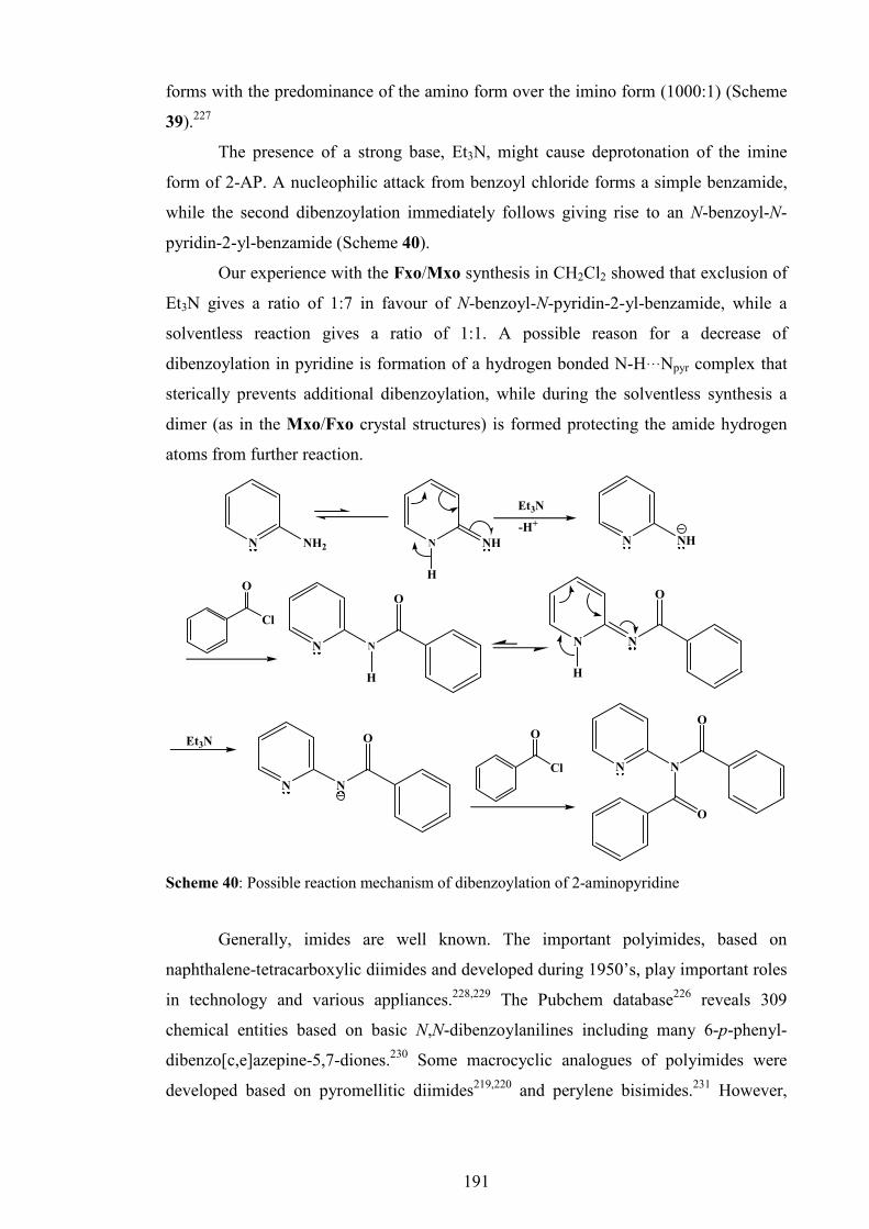
191
forms with the predominance of the amino form over the imino form (1000:1) (Scheme
39).227
The presence of a strong base, Et3N, might cause deprotonation of the imine
form of 2-AP. A nucleophilic attack from benzoyl chloride forms a simple benzamide,
while the second dibenzoylation immediately follows giving rise to an N-benzoyl-N-
pyridin-2-yl-benzamide (Scheme 40).
Our experience with the Fxo/Mxo synthesis in CH2Cl2 showed that exclusion of
Et3N gives a ratio of 1:7 in favour of N-benzoyl-N-pyridin-2-yl-benzamide, while a
solventless reaction gives a ratio of 1:1. A possible reason for a decrease of
dibenzoylation in pyridine is formation of a hydrogen bonded N-H···Npyr complex that
sterically prevents additional dibenzoylation, while during the solventless synthesis a
dimer (as in the Mxo/Fxo crystal structures) is formed protecting the amide hydrogen
atoms from further reaction.
NN
O
O
Cl
O
N NH2 N NH
Et3N
N NH
N N
O
Cl
O
N N
O
N N
O
H
Et3N
H
H
-H+
Scheme 40: Possible reaction mechanism of dibenzoylation of 2-aminopyridine
Generally, imides are well known. The important polyimides, based on
naphthalene-tetracarboxylic diimides and developed during 1950’s, play important roles
in technology and various appliances.228,229 The Pubchem database226 reveals 309
chemical entities based on basic N,N-dibenzoylanilines including many 6-p-phenyl-
dibenzo[c,e]azepine-5,7-diones.230 Some macrocyclic analogues of polyimides were
developed based on pyromellitic diimides219,220 and perylene bisimides.231 However,

192
apart from IYURAV and IYUQUO218 no imide macrocycles of the type [-(O)C-NR-
C(O)-]n (n ≥ 2) have been reported to date.
In the research group of J. F. Gallagher, from 2004 onwards, when condensing
acyl chlorides and acids with the ortho-aminopyridines, the imide products were always
regarded as interesting side-products to a variety of benzamide reactions that were being
studied. The first researcher to work on these was Dr. Steven Alley who was working
with ferrocene derivatives during 2002-2004. This was later exploited by Katie
Donnelly, a final year undergraduate student in early 2007.162-164
Attempts to synthesise N-(4-pyridin-2-yl)-N-(pyridinecarbonyl)pyridinecarboxamides
(August 2009) ended without success since products proved to be unstable and in
contact with silica gel decompose into N-(pyridin-2-yl)pyridinecarboxamides.
On December 8th 2009 during a routine, general CSD8 search through analogues
of our simple imides (Mxod, Fxod) the structures of the tetrameric imide macrocycles
IYURAV and IYUQUO218 were found and analysed. In these macrocycles, formation of
the tetrameric imide macrocycle was facilitated by the presence of 4 or 5 fluorine atoms
on a fluoroaniline moiety. A large number of fluorine atoms cause withdrawal of
electrons and as a consequence the pKa of the amine is lowered. A similar effect was
seen in 2-aminopyridine, however it is caused by electron delocalisation with the ortho-
nitrogen. An overlay of our imides163,164 with the IYURAV/IYUQUO218 scaffolds
showed a reasonable (yet remarkable) fit of the non-hydrogen atoms. This spurred the
idea to develop similar “4+4” tetrameric imide macrocycles, analogues of
IYURAV/IYUQUO using 2-aminopyridine instead of tetra- or pentafluoroaniline.218
This merging of IYURAV/IYUQUO218 type scaffolds with dibenzoylation of 2-
aminopyridine was planned to be accomplished by reacting 2-aminopyridine with the
isophthaloyl dichloride in CH2Cl2 as a reaction medium, in the presence of Et3N as base
and DMAP as catalyst. It was expected to obtain the main tetrameric macrocycle, high
molecular weight oligomers and polymeric materials.
The first attempt to undertake the “4+4” reaction was performed by Mark Farrell
in April 2010 with no apparent success. A second attempt, undertaken by Pavle Mocilac
(December 2010) gave a mixture of polymeric resin with dozens of low-molecular
compounds that proved to be very difficult to separate.
In order to simplify the mechanism and increase the statistical probability of
macrocycle formation we decided to try an alternative synthetic route, the “2+2”
reaction of equimolar amounts of N1,N3-di(pyridin-2-yl)isophthalamide (H-DIP)
(Scheme 41) with isophthaloyl dichloride in CH2Cl2 as solvent and in the presence of

193
Et3N and DBU as bases using high dilution techniques. In order to avoid
dibenzoylation, N1,N3-di(pyridin-2-yl)isophthalamide (H-DIP) was synthesised by
refluxing (at 110°C) isophthalic acid with double equivalents of 2-AP in presence of
triphenyl phosphite (TTP) as a coupling agent and pyridine as solvent. A detailed
procedure for the H-DIP synthesis is given in the Section 2.1. Reaction of H-DIP with
isophthaloyl dichloride using the high dilution technique (Scheme 42) ought to have
given a high yield of the desired macrocyclic product with a minimum amount of by-
products and polymers. As isophthalic dichloride reacts with water, the solvent used in
large quantities as reaction medium, CH2Cl2, was supposed to be strictly anhydrous,
since even a smallest amount of moisture can deactivate isophthalic dichloride.
HN
O
HN
O
NN
N1,N3-di(pyridin-2-yl)isophthalamide," H-DIP"
OH
O
HO
O
N NH2
TTP/pyridine/110°C
Scheme 41: Synthesis of N1,N3-di(pyridin-2-yl)isophthalamide (H-DIP)
The first “2+2” reactions were undertaken by Pavle Mocilac on 24th January
2011 yielding a mixture of H-DIP, polymer and additional side-products. A detailed
procedure of the “2+2” reaction is given in the Section 2.2. The products were separated
by column chromatography and subsequently re-crystallised from methanol. Three
fractions of small amounts of unknown material were recovered and the 1H-NMR in
DMSO at RT was recorded.
Cl
O
Cl
O
TEA, DBU CH2Cl2, N2
N
N
O O
**
4
HN
O
HN
O
NN
Scheme 42: General scheme for the “2+2” reactions
The first and the third fractions proved to be open chain compounds. However, the
second fraction showed a similar pattern of wide and overlapping peaks as in the Gale
& Evans publication.218 This indicated a macrocycle. A potential product was assigned
as IO4 (Isophthalic - Ortho-aminopyridine tetramer). The possible existence of the
“IO2” dimeric macrocycle was discounted since it is sterically unlikely.

194
The first real breakthrough came on the February 26th 2011, when a variable
temperature 1H-NMR experiment was undertaken raising the temperature from 20°C to
80°C in increments of 10°C. The results including a number of peaks, with shifts and
integration were as expected for an imide macrocycle.
An attempt to undertake a mass spectroscopy experiment in order to determine
the molecular weight, and consequently decide on the product’s final identity failed due
to insolubility in water and inability to ionise using electron spray ionisation or
MALDI-TOF methods. Nevertheless, in the absence of an appropriate MS result the
alternative was to grow a single crystal and solve the molecular and crystal structure.
The first crystal structure determination attempt was on IO4 grown from
CDCl3/CH3CN on March 7th and using Mo Kα radiation, (20s/30s to 0.85 Å) on a thin
colourless plate (that looked twinned). In fact all of the samples looked twinned and had
a soapy surface appearance to the untrained eye. The first structural breakthrough was
with a CDCl3 derived sample from an NMR tube and in a glass vial as [11-032]. The
crystal diffracted very well and to 0.95 Å for Cu and Mo Kα radiations. This was the
major breakthrough since the molecular and crystal structure proved that the product
was indeed the tetrameric imide macrocycle IO4.
Subsequently, DMSO crystals looked very poor and were eventually examined
as [11-041]. These crystals look twinned, but when viewed from the side though they
extinguish plane-polarised light. Crystal samples were then grown from alcoholic
solvents and crystals were examined in the following samples: from methanol [11-040]
data collected with Cu Kα radiation, but was found to be monoacetone solvate, from
ethanol as [11-038] (Mo Kα) and [11-039] (Cu Kα) and from IPA [11-042] (Cu Kα).
Crystals grown from IPA did not provide good quality data, but yielded a unit cell.
Table 37: List of IO4 crystals (at RT)
Label Emp. form. Kαααα R1 Date SG Θmax, Res. Remark [11-032] C53H33N8O8Cl3 Mo 5.59 07/03/2011 P̅1 [25°]; 0.85 IO4:CHCl3
[11-033] C53H33N8O8Cl3 Cu 4.50 08/03/2011 P̅1 [60°]; 0.88 IO4:CHCl3
[11-038] C53H35N8O8.5 Mo 6.11 23/03/2011 C2/c [25°]; 0.85 IO4:0.5(EtOH) [11-039] C53H35N8O8.5 Cu 3.38 24/03/2011 C2/c [60°]; 0.88 IO4:0.5(EtOH) [11-040] C53H35N8O8.5 Cu 4.69 25/03/2011 C2/c [60°]; 0.88 IO4:0.5(Acet) [11-041] C56H46N8O10S2 Cu 18.0 28/03/2011 C2 [60°]; 0.88 IO4:2(DMSO) [11-042] C58H46N8O10 Cu N/A 29/03/2011 C2/c [50°]; 1.00 IO4:2(IPA)
On March 22nd an ethanol crystalline derivative was mounted which was very
small, but later a huge block was mounted which had many faces. This crystal gave a
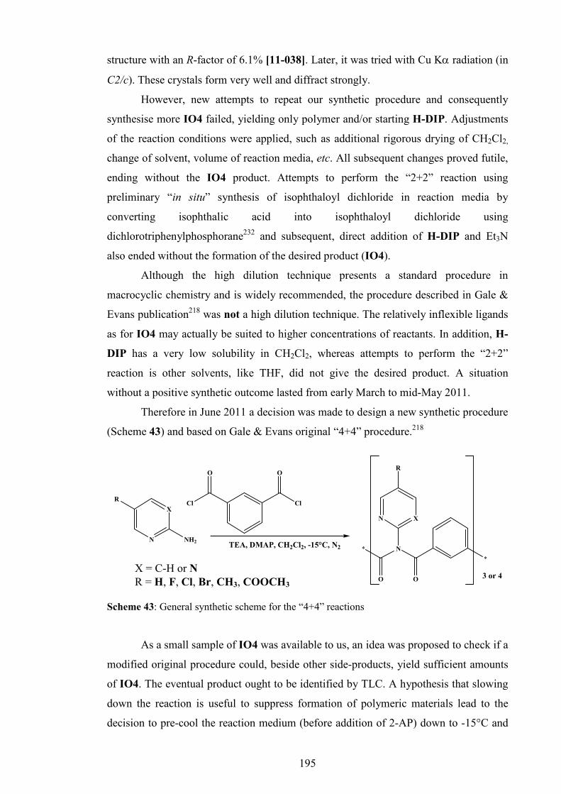
195
structure with an R-factor of 6.1% [11-038]. Later, it was tried with Cu Kα radiation (in
C2/c). These crystals form very well and diffract strongly.
However, new attempts to repeat our synthetic procedure and consequently
synthesise more IO4 failed, yielding only polymer and/or starting H-DIP. Adjustments
of the reaction conditions were applied, such as additional rigorous drying of CH2Cl2,
change of solvent, volume of reaction media, etc. All subsequent changes proved futile,
ending without the IO4 product. Attempts to perform the “2+2” reaction using
preliminary “in situ” synthesis of isophthaloyl dichloride in reaction media by
converting isophthalic acid into isophthaloyl dichloride using
dichlorotriphenylphosphorane232 and subsequent, direct addition of H-DIP and Et3N
also ended without the formation of the desired product (IO4).
Although the high dilution technique presents a standard procedure in
macrocyclic chemistry and is widely recommended, the procedure described in Gale &
Evans publication218 was not a high dilution technique. The relatively inflexible ligands
as for IO4 may actually be suited to higher concentrations of reactants. In addition, H-
DIP has a very low solubility in CH2Cl2, whereas attempts to perform the “2+2”
reaction is other solvents, like THF, did not give the desired product. A situation
without a positive synthetic outcome lasted from early March to mid-May 2011.
Therefore in June 2011 a decision was made to design a new synthetic procedure
(Scheme 43) and based on Gale & Evans original “4+4” procedure.218
N
X
NH2
Cl
O
Cl
O
TEA, DMAP, CH2Cl2, -15°C, N2
R
N X
N
O O
R
*
*
3 or 4
Scheme 43: General synthetic scheme for the “4+4” reactions
As a small sample of IO4 was available to us, an idea was proposed to check if a
modified original procedure could, beside other side-products, yield sufficient amounts
of IO4. The eventual product ought to be identified by TLC. A hypothesis that slowing
down the reaction is useful to suppress formation of polymeric materials lead to the
decision to pre-cool the reaction medium (before addition of 2-AP) down to -15°C and
X = C-H or N R = H, F, Cl, Br, CH3, COOCH3
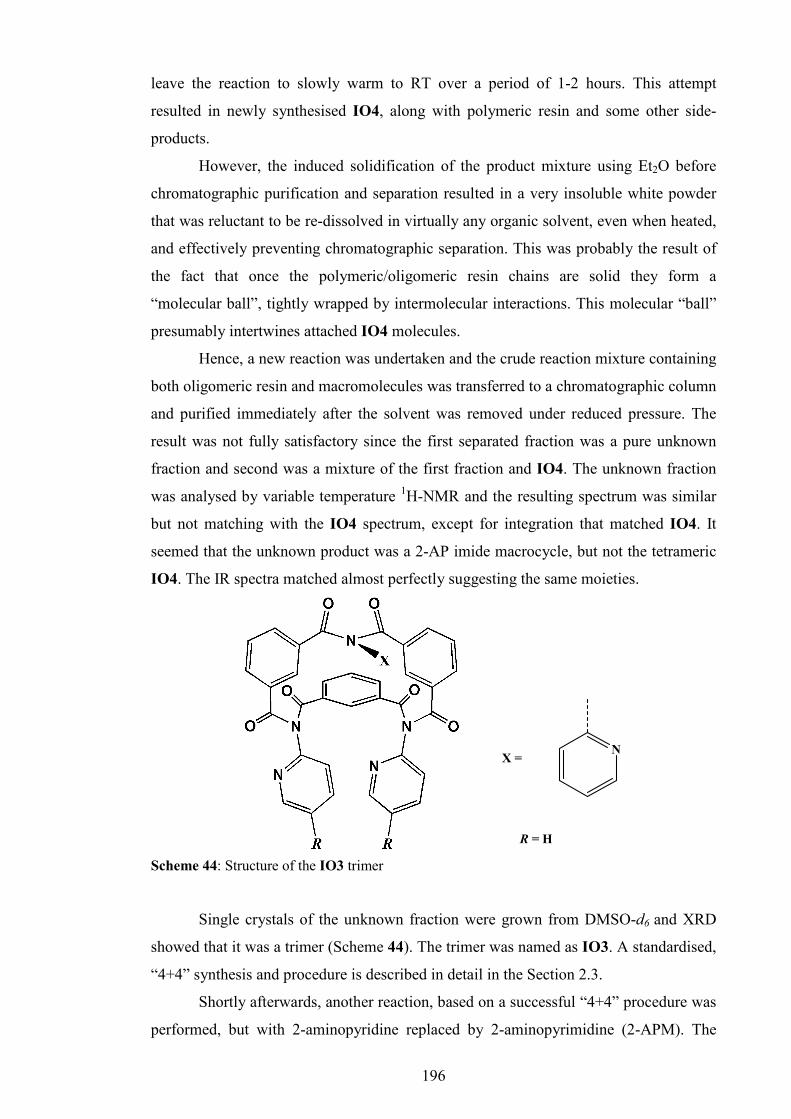
196
leave the reaction to slowly warm to RT over a period of 1-2 hours. This attempt
resulted in newly synthesised IO4, along with polymeric resin and some other side-
products.
However, the induced solidification of the product mixture using Et2O before
chromatographic purification and separation resulted in a very insoluble white powder
that was reluctant to be re-dissolved in virtually any organic solvent, even when heated,
and effectively preventing chromatographic separation. This was probably the result of
the fact that once the polymeric/oligomeric resin chains are solid they form a
“molecular ball”, tightly wrapped by intermolecular interactions. This molecular “ball”
presumably intertwines attached IO4 molecules.
Hence, a new reaction was undertaken and the crude reaction mixture containing
both oligomeric resin and macromolecules was transferred to a chromatographic column
and purified immediately after the solvent was removed under reduced pressure. The
result was not fully satisfactory since the first separated fraction was a pure unknown
fraction and second was a mixture of the first fraction and IO4. The unknown fraction
was analysed by variable temperature 1H-NMR and the resulting spectrum was similar
but not matching with the IO4 spectrum, except for integration that matched IO4. It
seemed that the unknown product was a 2-AP imide macrocycle, but not the tetrameric
IO4. The IR spectra matched almost perfectly suggesting the same moieties.
NX =
R = H
Scheme 44: Structure of the IO3 trimer
Single crystals of the unknown fraction were grown from DMSO-d6 and XRD
showed that it was a trimer (Scheme 44). The trimer was named as IO3. A standardised,
“4+4” synthesis and procedure is described in detail in the Section 2.3.
Shortly afterwards, another reaction, based on a successful “4+4” procedure was
performed, but with 2-aminopyridine replaced by 2-aminopyrimidine (2-APM). The

197
result gave a mixture of two imide macrocycles, namely the tetrameric 26IO4 and
trimeric 26IO3. The difference between the IO4/IO3 and 26IO4/26IO3
chromatographic Rf values was too small and classical column chromatography was
unable to separate both macrocycles efficiently. Gel permeation chromatography, as
described in Gale’s work,218 was not successful either. Therefore, after many attempts,
preparative TLC technique was tried and proved to be successful yielding ~5-10 mg of
each compound per plate. Using this method, sufficient amounts of 26IO4 and 26IO3
were isolated for spectroscopic analysis, crystal growth and XRD. Later in 2011 optimal
mobile phases for the efficient separation of the two different macrocycles were found
and preparative TLC was no longer required.
By the end of 2011 several pairs of imide macrocycles based on 2-AP or 26-
APM derivatives bearing different substituents were successfully synthesised, purified,
characterised and their structures determined by SXRD: FIO4/FIO3, ClIO4/ClIO3,
BrIO4/BrIO3, 26BrIO4/26BrIO3 and finally EsIO4/EsIO3. Methyl macrocycle
development ended with only the isolated tetramer (MIO4). However, repeated
attempts to synthesise the CNIO and 25IO macrocycles, based on 6-amino-3-
pyridinecarbonitrile and 2-aminopyrazine, failed and yielded no macrocycles.
Nevertheless the synthetic route is quite general and standard, allowing access to a
range of macrocycles (trimer/tetramer) based on 2-aminopyridines and 2-
aminopyrimidines.
1.3. Polymer formation
A competitive reaction that occurs in parallel with the cyclisation is the
formation of an imide polymer (polyimide, Scheme 45). The polymer probably has
medium and longer sized spiral chains with free terminal carboxylic groups that emerge
through partial deactivation of isophthaloyl dichloride with moisture from the
environment.
The standard strategy in preventing formation of the polymer is the high dilution
technique, but in this reaction this approach is not a choice. Instead, cooling of the
reaction mixture (-15°C) and reaction slowdown probably helps macrocycle formation.
The formation of polymer becomes visible usually after half an hour from the reaction
onset, as a clouding of the reaction mixture. When a reaction mixture gradually warms
to ambient temperature, the polymer becomes more visible and deposits in the form of a
gel on the flask wall.

198
O
N
O
X N
R
n
NHO
O O O O
OH
NX
R
Scheme 45: Possible structure of the imide polymer (X = C-H/N, R = H, F, Cl, Br, COOCH3)
During filtration on a sintered funnel the polymer as a gel, shrinks and thickens
into a paste as it loses solvent (CH2Cl2). Finally, after drying it hardens and solidifies
into a hard, brittle solid, insoluble in water and most organic solvents. Once dry and
hard it is reluctant to re-absorb solvents; solidification seems to be irreversible. Since it
is brittle, it can be easily obtained in a powdered form with a mortar and pestle. When in
contact with concentrated and warm acids (e.g. H2SO4) the polymer undergoes fast
degradation.
1.4. The labelling system and nomenclature
Since both the tetramers and trimers consist of the same fragment, 2-
aminopyridine or 2-aminopyrimidine and isophthalic acid connected by the imide
moiety, the main label “IO” is taken from the term “Isophthalic” and “Ortho-
aminopyridine”. The prefix “26” is assigned to macrocycles based on 2-
aminopyrimidine (26-APM). The suffixes “3” or “4” mark if the macrocycle is tetramer
or trimer. Finally, additional prefix before the IO label (F, Cl, Br, M [for CH3], and Es
[for COOCH3]) denotes substituent at the 2-AP or 26-APM in para-position.
All developed imide tetramer or trimer macrocycles share a similar backbone. In
the case of the tetramers, it is an irregularly shaped globular molecule with C4
pseudosymmetry. If the 2-AP moieties, hydrogen atoms and CX4/5/6 atoms are
removed the remaining backbone roughly follows a tennis ball seam. Therefore, for all
tetrameric imide macrocycles of similar geometry a common name “tennimides“ is
proposed. Similarly, for the trimeric imide macrocycles a common name “trezimides“
is proposed that originated from the Latin word “tres“ meaninig “three“. In order to
have a unique name the letter “s“ is changed into “z“.

199
1.5. Materials, equipment and spectroscopic methods
All vendors, materials, solvents and reagents and equipment for the synthesis,
purification and spectroscopic characterisation were as described in Chapter I, Section
1.1.2. Preparative TLC plates were purchase from Analtech Inc., USA. The NMR
spectra experiments have been performed in DMSO-d6, except for EsIO4 and EsIO3
(CDCl3), at 600 MHz using a Bruker Avance Ultrashield 600 NMR Spectrometer. For
most of the compounds variable temperature 1H-NMR, as well as 1H-NMR, 13C-NMR,
DEPT, DEPT-Q, HSQC, HMBC, COSY and NOESY experiments were undertaken at
higher temperature. For FIO3 and FIO4 the 19F-NMR experiments have been
performed at 400 MHz on an equivalent Bruker NMR spectrometer. The FTIR
experiments were performed as described in Chapter II.
1.6. X-ray crystallographic methods
Single crystal X-ray data collection and data reduction,176 structure solution and
refinement3,168 was as described for compounds in Chapter I. For some macrocycles, the
SQUEEZE program169 in PLATON was used in order to eliminate the regions of diffuse
electron density in solvent accessible voids. Selected crystallographic and structural
information are detailed in the ESI III, Section 2. Molecular and hydrogen bonding
diagrams (Figs. 79-101) were generated as described in other isomer grids (with
displacement ellipsoids drawn at the 10% probability level).169
1.7. Computational methods
The structural geometries of the IO3 and 26IO3 trezimides and IO4 and 26IO4
tennimides were investigated by ab initio modelling and conformational analysis
methods similar to that previously described (Chapter I and II) in order to test structural
differences between the experimentally obtained solid state structures (from X-ray
diffraction) and the modelled, optimised structures in gas phase. The experimental XRD
derived conformations were used as a starting point, and all calculations were
performed using the DFT method (B3LYP) and 6-31G(d,p) basis set. Calculations were
performed with Gaussian 09 software at the Irish Centre for High End Computing
(ICHEC).

200
2. Detailed descriptions of the synthetic procedures
2.1. Synthesis of N1,N3-di(pyridin-2-yl)isophthalamide (H-DIP)
Into a solution of isophthalic acid (2.08 g, 12.5 mmol) in 40-50 ml pyridine, 2-
aminopyridine (3.54 g, 37.5 mmol) was added and warmed with stirring for 15 minutes,
followed by addition of triphenyl phosphite (9.9 ml, 37.5 mmol). The reaction mixture
was refluxed with stirring at 110°C for 5 hours. Next, the pyridine was removed from
the reaction mixture by evaporation under reduced pressure on a rotary evaporator. The
resulting light brown oil was taken in 150 ml of CH2Cl2 and the solution was washed
with brine. The product was extracted in 150 ml 1:1 (v/v) aqueous HCl. The acidic
aqueous extract was neutralised by NaOH and Na2CO3. The resulting white solid was
filtered, washed thoroughly with distilled water, air dried and dissolved in 150-200 ml
of CH2Cl2. The solution was washed twice with aqueous solution of KHCO3/Na2CO3
(pH ~9). The organic layer was dried with MgSO4, decolourised with charcoal and
double filtered. The product (m = 1.4 g; 35%) was recovered after the solvent
evaporation under reduced pressure on a rotary evaporator.
2.2 Method 1: The “2+2” synthesis of the IO4 tennimide
The N1,N3-di(pyridin-2-yl)isophthalamide (H-DIP, 0.1783 g, 0.56 mmol) and
Et3N (0.24 ml, 1.68 mmol) were dissolved in anhydrous CH2Cl2 (400 ml) under N2 and
DBU (two drops, 35.2 µl, 0.2360 mmol) was added. Isophthaloyl dichloride (0.1137 g,
0.56 mmol) was added to the vigorously stirred reaction mixture. The reaction mixture
was allowed to vigorously stir overnight. The reaction mixture was washed with an
aqueous solution of KHCO3/Na2CO3 (400 ml, pH ~9) three times, with brine containing
NH4Cl (400 ml, pH ~6) three times, dried over MgSO4 and the solvent reduced on a
rotary evaporator affording a yellow resin. The yellow resin was purified by column
chromatography using silica as stationary phase and CH2Cl2/MeOH (10:1) as a mobile
phase. The resulting second fraction was collected, the product was recovered and re-
crystallised from MeOH affording 26.6 mg (10.6%) of a white product (IO4).

201
2.3. Method 2: Standardised, “4+4” synthesis of tennimides and trezimides
The reaction medium was prepared by dissolving DMAP (10 mg, 0.08 mmol)
and Et3N (4 ml, 29.8 mmol) in 100 ml of anhydrous CH2Cl2. The 2-aminopyridine, 2-
aminopyrimidine or its derivative (9.8 mmol) was dissolved or suspended in 5-20 ml of
reaction media. Isophthaloyl dichloride (1.98 g, 9.8 mmol) was dissolved with stirring
in 80-95 ml of reaction media in a 250 ml round bottom flask, under an inert
atmosphere of N2 and cooled on an ice bath (ice/NaCl/NH4Cl/EtOH) to -15°C. The
solution/suspension of 2-aminopyridine, 2-aminopyrimidine or derivative was quickly
and quantitatively added to the cooled flask containing isophthaloyl dichloride. The
reaction mixture was stirred overnight.
The reaction mixture was diluted with technical grade CH2Cl2 to 200 ml, if
necesary filtered over a funnel with a sintered glass frit, to remove the polymeric by-
product and washed three times with aqueous solutions of NH4Cl (pH ~5) (3 × 200 ml),
dried over MgSO4 and filtered. The clear, filtered product solution was left for the next
step. Subsequently, the solvent was removed on a rotary-evaporator to afford a resin.
This resin was immediately purified by column chromatography on silica gel (Davisil,
70 µm, 82 g, column dimension: l = 25 cm, d = 3 cm) eluting with a suitable mobile
phase to separate and obtain pure macrocyclic products. Isolated yields were from 3 to
13% for both tennimide and trezimide macrocycles.
3. General comments on spectroscopic data
Spectroscopically, the tennimides and trezimides show C4/C3 pseudosymmetry, having
four/three equivalent segments that consist of 2-aminopyridines (or 2-
aminopyridimidines) and the isophthalic moiety. Therefore, all tennimides and
trezimides can be considered as tetramers and trimers of a general segment shown in
Scheme 46. Due to conformational rigidity in solution at room temperature, the 1H
NMR experiment at 20°C usually shows very poorly resolved peaks, giving
inappropriate integration. However, raising the temperature improves flexibility and
peaks were gradually resolved at 80°C.
The variable temperature 1H-NMR was recorded for all compounds (except for
EsIO3) showing significant improvements of peak resolution as well as displacement of
particular peaks at higher temperatures. This effect is less pronounced in the trezimides
than in the tennimides. For 26IO4 and 26BrIO4 a higher temperature (120°C and

202
140°C) was required due to the low solubility in DMSO-d6. Elevation of temperature
improved the 13C-NMR spectra too. The NOESY experiments did not show any specific
proximity of protons in solution.
X N
N
O 4/3O
∗∗∗∗
∗∗∗∗
R
Scheme 46: Tennimides and trezimides (X = C-H/N, R = H, F, Cl, Br, CH3, COOCH3)
4. IO3 and IO4 macrocycles
4.1. Synthesis and purification
The synthesis and purification of the IO3 trezimide and IO4 tennimide was as
described in previous sections (1 and 2, Scheme 41-43). The yield were good to modest:
the yield of IO4 obtained with Method 1 (Section 2.1) was 26.6 mg (10.6%) while with
Method 2 (Section 2.2) it was 127 mg (6%), for IO4 and 149 mg (7%) for IO3. The
chromatographic Rf values for the CHCl3/ethyl acetate/acetone (4:12:1) mobile phase
were 0.57 (IO4) and 0.63 (IO3).
4.2. General and spectroscopic data
The IO3 trezimide and IO4 tennimide are white, odourless powders. Their
crystallinity is comparable with those of the benzamides and pyridinecarboxamides,
however, better than that of carbamates and H-DIP. The IO3 seems to be more soluble
in organic solvents than IO4; the solubility difference is especially pronounced in
alcohols, IO3 is readily soluble, while IO4 is poorly soluble in cold methanol, ethanol
or iso-propanol. However, both compounds are soluble in chlorinated hydrocarbons,
such as CHCl3 or CH2Cl2 as well as in ethyl acetate, acetone and DMSO. Solubility in
n-hexane was modest, poor in diethyl ether. Both IO4 and IO3 are insoluble in water.
The basic spectroscopic information for H-DIP, IO4 and IO3 is given in
Appendix I, Sections 4.1 - 4.3, while the comprehensive NMR data and spectra are

203
given in the ESI III, Section 1-3. The 1H-NMR of IO4 resolves relatively well at 80°C
without coupling (Fig. 78a), whereas for IO3, peaks resolve much better and
decoupling shows. This suggests that IO3 is much more flexible than IO4 where more
than one conformation exists. The IR data (Fig. 78b) are almost identical and show a
similar distribution of bands with very strong bands around 1720-1690 cm-1
corresponding with carbonyl (C=O) stretches The peaks in 1600-1400 cm-1 region are
associated with C-C and C-N vibrations in the isophthaloyl and pyridinyl rings, while
the strong peaks in the 1400-1200 cm-1 region belong to C-N and C-C vibrations and
Fig. 78a: Variable temperature 1H-NMR experiment for IO4 and IO3
Fig. 78b: IR spectrum of IO4

204
stretches in the imide backbone. Absence of significant peaks ca. 3000 cm-1 indicates
that the bulk IO3 and IO4 powders are not in the form of solvate. The stability of IO4
seems to be very good and better than the stability of IO3. Prolonged heating in DMSO-
d6 did not cause disintegration. However, separation using preparative TLC caused
partial disintegration of IO3 suggesting potential stability issues.
4.3. Crystallographic data and discussion
For all crystal structures an initial data collection using Mo radiation provided
adequate results with R factors from 0.06 to 0.12, however Cu datasets were also
obtained providing more data, much lower R-factors (R < 0.06) and smaller estimated
standard deviations on the geometric parameters: the Cu-derived data are discussed
herein. Since several single crystals of IO4 were grown and data was collected,
affording various R-factors, the results of the [11-033] dataset (IO4:CHCl3) will be
presented. Table 38 summarises the basic crystallographic data.
Table 38: Selected crystallographic dataa for the IO3 and IO4 macrocycles†
IO3 IO4
Chemical formula C39H24N6O6·(C2H6OS)2 C52H32N8O8·CHCl3 Crystal system, space group Monoclinic,
P21/n, (No. 14) Triclinic P̅1, (No. 2)
a, b, c (Å) 12.5381(1), 11.7299(1), 28.1349(3)
11.9279(9), 12.0291(9), 16.8723(13)
α, β, γ (°) 90, 92.935(1), 90 84.618(6), 86.984(6), 76.201(7)
Z' 1 1 R[F2 > 2σ(F2)], wR(F2), S 0.057, 0.163, 1.05 0.045, 0.123, 1.04 † Complete crystallographic, refinement and structural details are listed in the ESI III (Section
2.1). a Obtained with Cu Kα radiation.
The IO3 trezimide (Fig. 79) crystallises as a solvate with two molecules of
DMSO-d6. The solvent molecules are disordered as A/B (0.5:0.5) and C/D (0.5:0:5).
The solvent molecules play an important role in aggregation. If viewed along the c-axis
direction while the a-axis is down, the IO3 molecule roughly resembles to letter “A”
with two pyridinyl rings (“1” and “3”) being vertical, pointed down and nearly co-
parallel (interplanar angle P1/P3 = 34.67°). The pyridinyl ring “2” is located at the top
and is directed backward. The isophthaloyl ring “1” is nearly perpendicular to the two
pyridinyl rings “1” and “3” (interplanar angles I1/P1 = 81.22° and I1/P3 = 87.41°).

205
The internal imide dihedral angles, or so called “CO···CO” twist angles are -
87.03° (O1-C1···C2-O2), 95.45° (O3-C3···C4-O4) and 94.85° (O5-C5···C6-O6). The
wide pocket between the carbonyl moieties (O2, O3, and O5) and isophthaloyl
hydrogen atoms (H12, H22 and H32) is a macromolecular niche and its dimensions are
defined by O···O and H···H distances.
Fig. 79: An ORTEP diagram of IO3; a) with solvent molecules b) with macrocyclic niche
For IO3 the O···O distances range from 6.05 to 7.96 Å, while the H···H
distances range from 2.67 to 2.87 Å. The disordered A/B molecule of DMSO-d6 is
anchored to the macromolecular niche via strong C16A-H16A···O1D [C16A···O1D =
3.246(12) Å] and C36A-H36A···O1C [C36A···O1C = 3.195(12) Å] hydrogen bonds.
The two disordered DMSO-d6 molecules, A/B and C/D are interconnected via C1C/D-
H15C/D···O1A/Ba [a = 3/2-x,1/2+y,1/2-z] interactions.
The aggregation in IO3 is mainly accomplished through C-H···O/N contacts
with the aid of interactions between the solvent and IO3 molecules. The main
interaction is a C35A-H35A···O2b [C35A···O2b = 3.148(4) Å, b = -x+1/2,y+1/2,-z+1/2]
hydrogen bond that alternately links IO3 molecules into a zig-zag 1-D column along the
b-axis direction. The column is stabilised by weaker C15A-H15A···O5c [C15A···O5c =
3.400(3) Å, c = 1/2-x,-1/2+y,1/2-z] interactions. Secondary interactions are C34A-
H34A···O3d [C34A···O3d = 3.306(4) Å, d = x-1,y,z] and C25-H25···O3e [C25···O3e =
3.096(3) Å, e = -x+3/2,y-1/2,-z+1/2] that interconnect the zig-zag columns, aided by the
C24A-H24A···N12Af [C24A···N12Af = 3.385(3) Å, f = i-x+1,-y+1,-z] interaction. The
a b
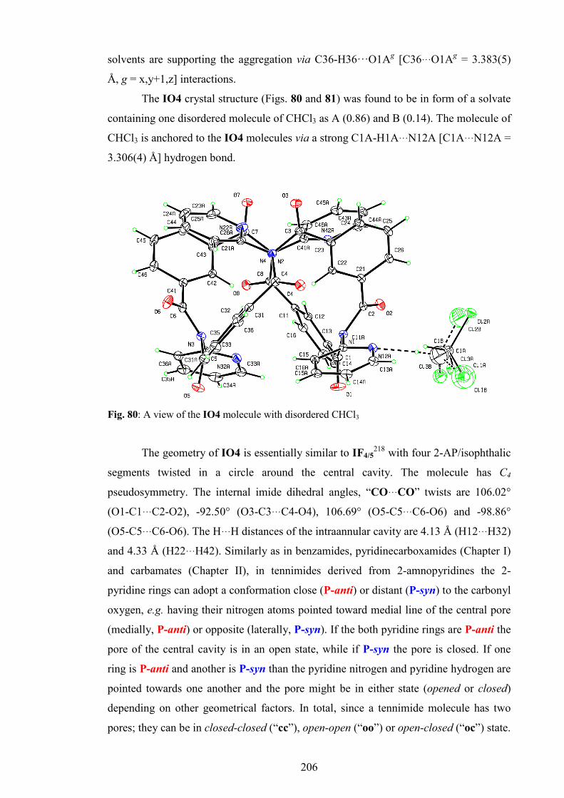
206
solvents are supporting the aggregation via C36-H36···O1Ag [C36···O1Ag = 3.383(5)
Å, g = x,y+1,z] interactions.
The IO4 crystal structure (Figs. 80 and 81) was found to be in form of a solvate
containing one disordered molecule of CHCl3 as A (0.86) and B (0.14). The molecule of
CHCl3 is anchored to the IO4 molecules via a strong C1A-H1A···N12A [C1A···N12A =
3.306(4) Å] hydrogen bond.
Fig. 80: A view of the IO4 molecule with disordered CHCl3
The geometry of IO4 is essentially similar to IF4/5218 with four 2-AP/isophthalic
segments twisted in a circle around the central cavity. The molecule has C4
pseudosymmetry. The internal imide dihedral angles, “CO···CO” twists are 106.02°
(O1-C1···C2-O2), -92.50° (O3-C3···C4-O4), 106.69° (O5-C5···C6-O6) and -98.86°
(O5-C5···C6-O6). The H···H distances of the intraannular cavity are 4.13 Å (H12···H32)
and 4.33 Å (H22···H42). Similarly as in benzamides, pyridinecarboxamides (Chapter I)
and carbamates (Chapter II), in tennimides derived from 2-amnopyridines the 2-
pyridine rings can adopt a conformation close (P-anti) or distant (P-syn) to the carbonyl
oxygen, e.g. having their nitrogen atoms pointed toward medial line of the central pore
(medially, P-anti) or opposite (laterally, P-syn). If the both pyridine rings are P-anti the
pore of the central cavity is in an open state, while if P-syn the pore is closed. If one
ring is P-anti and another is P-syn than the pyridine nitrogen and pyridine hydrogen are
pointed towards one another and the pore might be in either state (opened or closed)
depending on other geometrical factors. In total, since a tennimide molecule has two
pores; they can be in closed-closed (“cc”), open-open (“oo”) or open-closed (“oc”) state.
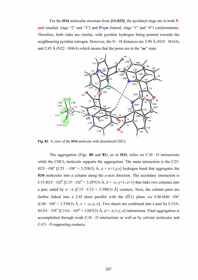
207
For the IO4 molecular structure from [11-033], the pyridinyl rings are in both P-
anti (medial, rings “2” and “3”) and P-syn (lateral, rings “1” and “4”) conformations.
Therefore, both sides are similar, with pyridine hydrogen being pointed towards the
neighbouring pyridine nitrogen. However, the N···H distances are 3.90 Å (N32···H16A)
and 2.85 Å (N22···H46A) which means that the pores are in the “oc” state.
Fig. 81: A view of the IO4 molecule with disordered CHCl3
The aggregation (Figs. 80 and 81), as in IO3, relies on C-H···O interactions
while the CHCl3 molecule supports the aggregation. The main interaction is the C25-
H25···O8a [C25 ···O8a = 3.238(3) Å, a = x+1,y,z] hydrogen bond that aggregates the
IO4 molecules into a column along the a-axis direction. The secondary interaction is
C15-H15···O2b [C15···O2b = 3.297(3) Å, b = -x,-y+1,-z+1] that links two columns into
a pair, aided by π···π [C15···C15 = 3.390(3) Å] contacts. Next, the column pairs are
further linked into a 2-D sheet parallel with the (0̅11) plane via C46-H46···O6c
[C46···O6c = 3.358(3) Å, c = -x,-y,-z]. Two sheets are combined into a pair by C15A-
H15A···O5d [C15A···O5d = 3.087(3) Å, d = -x,1-y,-z] interactions. Final aggregation is
accomplished through weak C-H…O interactions as well as by solvent molecules and
C-Cl···O supporting contacts.

208
5. 26IO3 and 26IO4 macrocycles
5.1. Synthesis and purification
The synthesis and purification of the 26IO3 tennimide and 26IO4 tennimide was
undertaken as described in the standardised “4+4” procedure (Section 2.3) using 2-
aminopyrimidine (26-APM, 0.932 g, 9.8 mmol) instead of 2-aminopyridine (2-AP). The
chromatographic separation was accomplished with a CHCl3/MeOH blend (10:1) as a
mobile phase, yielding the 26IO3 trezimide (89 mg, 4%, Rf= 0.579) and the 26IO4
tennimide (134 mg, 6%, Rf = 0.699). However, a further purification in order to obtain
highly pure samples for characterisation and crystal growth was undertaken using re-
crystallisation from CHCl3 and preparative TLC.
N
N
NH2
Cl
O
Cl
O
TEA, DMAP, CH2Cl2, -15°C, N2*
N
OO
*
NN
3/4
Scheme 47: General diagram of the 26IO3/4 synthesis
5.2. General and spectroscopic data
In general, the 26IO3 and 26IO4 macrocycles show similar physical properties as their
2-AP analogues, however, they are less soluble and more crystalline. Compared to IO4,
the 26IO4 tennimide is less soluble in most organic solvents even in DMSO. Therefore,
the NMR data for 26IO4 was obtained in DMSO-d6 at 120°C. The 26IO4 is
significantly less soluble in CHCl3 than 26IO3 and therefore can be separated from
26IO3 using a standard re-crystallisation procedure. Paradoxically, the 26IO4 shows
higher solubility in cold CHCl3 than in warm: if a cold solution with a few crystals is
heated new 26IO4 crystals are formed, but re-dissolve upon cooling. This unexpected
paradox occurs presumably due to easier aggregation of 26IO4 and CHCl3 into a
solvate after the structure of 26IO4 is conformationaly equalised in warmer conditions.
The 26IO4 tennimide shows higher crystallinity compared to IO4.
The NMR and IR data are listed in Appendix I, Sections 4.3 and 4.4, while the
spectra are given in the ESI III, Sections 1.3 and 1.4. The variable temperature 1H-NMR

209
was undertaken from 120°C down to 20°C. Peaks resolve at 80°C, while the coupling
fully emerges at 120°. The 26IO4/3 macrocycles show two protons less than the IO3/4
macrocycles. In 26IO3 peaks are fully resolved even at 20°C suggesting a high rate of
conformational interchange and flexibility.
5.3. Crystallographic data and discussion
Single crystals of 26IO3 (CH2Cl2/CHCl3 with MeOH) and 26IO4 (CH2Cl2/CHCl3)
were obtained using standard crystallization conditions in a range of common
solvents. Table 39 summarises the key crystallographic data for the 26IO3 trezimide
and for two datasets of the 26IO4 tennimide.
For 26IO4 a second crystal [11-104] was grown and the lattice voids contained
partial occupancy and disordered solvent molecules of CHCl3, acetone, methanol and
water (crystallisation arose after several successive attempts using more polar solvents).
In this case only, the SQUEEZE program was used to improve the overall results with
the R-factor dropping from 13.2 to 4.2%.
The 26IO3 trezimide (Fig. 82) crystallises as a solvate with a disordered
molecule of CHCl3 (partial occupancy of 0.25), CH2Cl2 (partial occupancy of 0.3) and
CH3OH (partial occupancy of 0.25). As seen previously, the disordered solvents are
creating additional networks of interactions supporting aggregation. The 26IO3 crystal
structure aggregates with Z’ = 2, although molecules seem to be very similar.
Table 39: Selected crystallographic dataa for the 26IO3 and 26IO4 macrocycles†
26IO3 26IO4-[11-103] 26IO4-[11-104]
Chemical formula C36.80H22.85Cl1.35N9O6.25 (C48H28N12O8)2·C3H5Cl7 C48H28N12O8 Crystal system, space group
Triclinic, P̅1
Tetragonal, P̅421c
Tetragonal, P̅421c
a, b, c (Å) 13.3884(4), 13.5458(4),
20.0062(7)
22.7814(1), 22.7814(1),
19.0308(1)
15.9127 (3), 15.9127 (3), 19.3896 (5)
α, β, γ (°) 76.205 (3), 89.176 (2), 89.633 (2)
90, 90, 90 90, 90, 90
Z' 2 3 1
R[F2 > 2σ(F2)], wR(F2), S
0.060, 0.176, 1.03 0.046, 0.136, 1.03 0.042, 0.116, 1.02
† Complete crystallographic, refinement and structural details are listed in the ESI III (Section
2.2). a Obtained with Cu Kα radiation.

210
The most striking characteristic of both 26IO3 molecular structures (Fig. 82) is
that they have very different conformations as compared to IO3. The two molecules (A
and B) are different and almost mirror images of each other. The molecular niches (Fig.
82) are located between the carbonyl oxygen atoms O1A, O3A and O6A (molecule A)
and O1B, O4B and O5B (molecule B); the O···O distances range from 6.71 to 6.92 Å
(molecule A) and from 6.61 to 7.25 Å (molecule B). The isophthalic H···H (H12, H22
and H32) distances range from 2.76 to 3.59 Å (molecule A) and from 2.71 to 3.67 Å
(molecule B). However, the internal imide “CO···CO” twist dihedral angles are 97.6°
(O1-C1···C2-O2), 66.1° (O3-C3···C4-O4) and -113.6° (O5-C5···C6-O6) in molecule A,
while in the molecule B are 116.3° (O1-C1···C2-O2), -70.44° (O3-C3···C4-O4) and -
79.5° (O5-C5···C6-O6). The interplanar angles between the isophthalic angles are close
to orthogonality; the 1A/3A interplanar angle is 80.8° and the 1B/3B is 85.1°. This
conformation was assigned as the R conformation, opposite to typical P conformation
of IO3.
Fig. 82: An ORTEP diagram of 26IO3 with macrocyclic niches shown: a) molecule
A, b) molecule B
The aggregation in 26IO3 is enhanced by solvent molecules that form a myriad
of intermolecular interactions. The main backbone of the crystal structure is a double 1-
D chain formed along the a-axis direction by molecules B via C16B-H16B···O3Ba
[C16B-H16B···O3Ba = 3.333(3) Å, a = -1+x,y,z] and C15B-H15B···N42Bb [C15B-
H15B···N42Bb = 3.415(4) Å, b = -x,1-y,1-z] interactions. Molecules A do not engage in
strong interconnections internally itself, but rather serve as a joints between the chains
of molecule B via several interactions such as C24A-H24A···O6B [C24A···O6B =
a b

211
3.194(4) Å], C53B-H53B···N62Ac [C53B···N62Ac = 3.418(5) Å, c = 1+x,1+y,z], C43A-
H43A···O4Bd [C43A···O4Bd = 3.286(6) Å, d = -x,1-y,-z] and C35B-H35B···O2Ae
[C35B···O2Ae = 3.212(5) Å, e = 1+x,y,z].
The 26IO4 structures are shown to be the most symmetric among the
tennimides. Both datasets crystallise in the P ̅421c space group with similar aggregation
patterns, but differ in Z' and geometry. In the [11-103] crystal 26IO4 crystallises with a
disordered molecule of CHCl3 with Z’ = 3: molecule A consists of two equivalent
halves (C2 symmetry) that stand in relation via symmetry code -x,1-y,z while the
molecules C and O have C4 symmetry with four identical segments (26-
APM/isophthalic) standing in relation by symmetry codes 1-y,x,-z, 1-x,1-y,z and y,1-x,-
z (Molecule C) and 1-x,1-y,z, 1-y,x,1-z and y,1-x,1-z (Molecule O). The molecules
differ by their geometry. In molecule A internal imide “CO···CO” twist angles are -
88.6° (O1-C1···C2-O2) and 96.5° (O3-C3···C4-O4), while in the molecule C and O only
one value exists due to the C4 symmetry, ±87.2° (molecule C) and ±91.9° (molecule O).
The H···H distances of the intraannular cavity in molecule A are 4.224 Å (H12···H12Aa,
a = -x,1-y,z) and 5.282 Å (H22···H22Aa), in the molecule C are 4.539 Å
(H12C···H12Cb, b = 1-x,1-y,z) and in the molecule O are 3.943 Å (H12O···H12Ob).
Fig. 83: An ORTEP and CPK view of 26IO4 ([11-103] dataset, molecule O)
The N22…N22 distances are 3.259 Å (N12···N12Aa), and 4.098 Å
(N22···N22Aa) in the molecule A, 3.520 Å (N22C···N22Cb) in the molecule C and
4.679 Å (N22O···N22Ob) in the molecule O. Therefore, it seems that the cavity pores in
the molecule A are in the open-closed state (“oc”), while the closed-closed (“cc”) in the
molecule C and the open-open (“oo”) in molecule O. In the same time intraannular

212
cavity in molecule A is distorted, in molecule C is expanded, while in molecule O is
constricted.
The aggregation in the 11-103 crystal structure relies on C-H···O interactions.
The molecules are connected into columns along the c-axis direction via C13A-
H13A···O4c [C13A···O4c = 3.121(4) Å, c = -1/2+y,1/2+x,1/2+z], C23C-H23C···O2Od
[C23C···O2Od = 3.310(6) Å, d = 1-x,1-y,z-1], C16O-C16H···O2Ce [C16O···O2Ce =
3.264(4) Å, e = y,1-x,-z] and C23A-H23A···O2f [C23A-H23A···O2f = 3.448 Å, f = -
1/2+y,1/2+x,-1/2+z] interactions.
Fig. 84: A side-view of 26IO4 ([11-103] dataset, molecule O)
The columns are linked along the a- and b-axes by C25O-H25O···O3g
[C25O···O3g = 3.258(4) Å, g = 1/2-x,-1/2+y,1/2-z], C15C-H15C···O1h [C15C···O1h =
3.159(3) Å, h = 1-y,1+x,-z] and C15A-H15A···O1Of [C15A···O1Of = 3.124(4) Å]
interactions.
The 11-104 crystal structure of the 26IO4 tennimide is very similar, but with Z'
= 1. The geometry of the 26IO4 molecule resembles molecule A from the 11-104
dataset, having C2 symmetry with symmetry code a = 1-x,-y,z. The internal imide
“CO···CO” dihedral twists are -81.05° (O1-C1···C2-O2) and 95.94° (O1-C1···C2-O2).
The H···H distances of the intraannular cavity are 4.355Å (H12···H12a) and 4.181 Å
(H22···H22a), while the pyrimidine N···N distances are 3.253 Å (N12···N12a) and 4.077
Å (N22···N22a). Therefore, cavity pores are in the open-closed “oc” state. Aggregation
in the 11-104 crystal structure is similar to [11-103]. The principal interaction is a
strong C13A-H13A···O3b [C13A···O3b = 3.166(3) Å, b = 1/2-y,1/2-x,-1/2+z] hydrogen

213
bond that aggregates molecules along the c-axis direction into a 1-D column. The
columns are interconnected into the 3-D structure along the a- and b-axes via C25-
H25···O4d [C25···O4d = 3.361(3) Å, d = 1-y,-1+x,-z], C26-H26···O3e [C26···O3e =
3.489 Å, e = 1-y,-1+x,-z] and C15-H15···N16Af [C15···N16Af = 3.476 Å, f = 3/2-
x,1/2+y,1/2-z] contacts.
5.4. Ab initio geometry optimisation, energies and conformational analysis
The geometry of the tennimides and trezimides structures was optimised by ab
initio modelling methods in order to investigate structural differences between the
experimentally obtained solid state structures and modelled optimised structure in gas
phase. The experimental XRD derived structures were taken as a starting point and all
calculations were performed using the DFT method (B3LYP) and 6-31G(d,p) basis set.
All optimisations were successful and did not produce vibrations with negative values.
To examine flexibility of the imide backbone, a structural fragment containing
two isophthalic and one 2-pyridinyl (2-pyrimidinyl) moieties was isolated from the non-
optimised IO4 and 26IO4 structures based on experimental solid state structures. The
main torsion angles of the fragments, 2-AP-ring angle, 26-APM-ring angle, two imide
torsion angles (O-C8-N-C, O-C9-N-C), two isophthalic angles (O-C8-C-C, O-C9-C-C),
(ESI III, Section 3, Fig. 1) were subjected to conformational analysis by performing
PES scans of each torsion angle while the rest of the torsion angles were kept static. By
this model, the rigidity of the tennimides was nullified and the PES scans were enabled.
However, as this model presents only an approximate model, the resulting PES
diagrams can be taken only as providing a generalised, approximate insight into the
flexibility of the imide backbone moiety. Furthermore, the structural fragments of both
IO4 and 26IO4 were optimised to inspect the extent of structural change after rigidity
was removed and relaxation achieved.
Since the IO3 and 26IO3 trezimides were found in two distinct conformations,
IO3-P and 23IO3-R, the hypothetical counter-conformations IO3-R and 26IO3-P were
built, based on the existing IO3-P and 23IO3-R conformations, by simple swapping of
the aromatic C-H atoms with aromatic N atom and the reverse. Both experimental and
hypothetical conformer geometries were optimised and the resulting geometries were
compared by simple structure overlays.
Optimisation of both IO4 and 26IO4 significantly equalises structural
parameters across the macrocycle making the structures more symmetrical (Fig. 85).

214
Most of the IO4 torsion angles in the main backbone rotate no more than 12° except for
the C31A-N3-C5-C33 (+16°) and O4-C4-C31-C32 (+13°) torsion angles (ESI III,
Section 3.1).
Fig. 85: left) overlay of solid state (in red) and optimised (in light green) IO4
structure; right) overlay of solid state (in red) and optimised (in light green) 26IO4
structure
Since a solvent molecule of CHCl3 was excluded from the modelling, pyridinyl
rings 2 and 3 significantly rotate closing the pore. Generally, the IO4 tennimide closes
the pores upon optimisation (H12···H32), height (O7···O6) increases, while diameter
(N2···N2a, a = 1-x,-y,z) slightly contracts (ESI III, Section 3.1).
For 26IO4 tennimide, the 2-aminopyrimidine rings significantly move apart
upon optimisation (~1-2 Å), opening the central cavity (Fig. 85). At the same time, the
isophthalic rings move slightly medially (~0.2-0.3 Å). In summation, the 26IO4
diameter (C3···C3a) slightly expands, its height (O3···O1) increases, while the central
pore (H12···H12a, N22A···N22Aa) was found to open. This is mainly due to the changes
in isophthalic torsion angles, less in imide torsion angles and 2-aminopyrimidine (26-
APM) ring, since the isolated molecule without intermolecular interactions adopts a
more stable and symmetric geometry.
The PES diagrams (ESI III, Section 3.2) show that the torsion angles of both
26IO4 and IO4 are approximately in their global minimum, except the 2-AP ring and
imide 8 torsion angles whose global minimum is in the negative value area. Apart from
slight tensions of the imide torsion angles caused by movement restriction in the
macrocycle, the result indicates no significant tensions in the IO4/26IO4 macrocycles.
Furthermore, optimisations of the IO4 and 26IO4 fragments (ESI, Section 3.3) show

215
larger changes of imide 8 torsion angles compared to other torsion angles, supporting
the indications drawn from PES diagrams. High rotational barriers of the imide and 26-
APM/2-AP torsion angles suggest relative inflexibility and opposite to the more flexible
isophthalic angles. In agreement with this, optimisation of 26IO4 causes more
significant changes in the isophthalic angles compensating for tension in imide torsion
angle.
All ab initio modelling information of the tennimides suggests that the solid
state structures of IO4 and 26IO4 are rigid and not particularly different from their
optimised model structures. Crystallisation with or without a solvent will not
significantly change the overall structural parameters, while the solid state geometries
are not expected to dramatically change upon dissolving in a solvent. Furthermore,
modelling information suggests that steric stability of the tennimides contributes to the
probability of tennimide formation.
Comparisons of the IO3-P and 26IO3-R solid state structures as well as their
hypothetical solid state counter-conformations (ESI III, Section 3.4) with their
optimised structures show no significant change in geometries apart from slight
rotations of the 2-AP and 26-APM rings. There were no negative values of the
calculated vibrations observed, which suggests that the optimised structures reached
their minima. The optimisation results suggest that the existence of both conformations
is likely and that conformational polymorphism is plausible.
6. FIO3 and FIO4 macrocycles
6.1. Synthesis and purification
The synthesis was as described for Method 2 (standard “4+4” reaction, Section
2.3) using 2-amino-5-fluoropyridine (1.0986 g, 9.8 mmol) as a functionalised 2-
aminopyridine (Scheme 48). The polymer was not precipitated – the reaction mixture
stayed clear overnight, suggesting better solubility of the polymer. Chromatographic
purification and separation was undertaken using a mobile phase containing CHCl3 and
ethyl acetate (4:1), yielding FIO4 (140 mg, 5.9%, Rf = 0.302) and FIO3 (150 mg,
6.3%, Rf = 0.202). The isolated FIO3 contained minor amounts of FIO4; therefore a
final re-purification was accomplished using preparative TLC.

216
6.2. General and spectroscopic data
The general characteristics of FIO3 and FIO4 macrocycles, such as colour and
crystallinity are broadly similar to the basic IO4 and IO3 macrocycles, however, its
solubility in organic solvents, especially in chlorinated hydrocarbons is better.
N NH2
Cl
O
Cl
O
TEA, DMAP, CH2Cl2, -15°C, N2
F
*N
OO
*
N
F
3/4
Scheme 48: General diagram of the FIO3/4 synthesis
Results of the NMR experiments at RT and 80°C (1H-, 13C- and 19F-NMR data
are listed in Appendix I, Sections 4.5 and 4.6, spectra are provided in the ESI III,
Sections 1.6 and 1.7) are comparable with those of the IO4 and IO3 macrocycles. Since
fluorine atoms were present, 19F-NMR experiments were undertaken including variable
temperature studies. In FIO3 two weak signals were noticed at RT at -129.8 and -128.7
ppm. At 40°C the signals merge into a one signal that intensifies and sharpens at -129.2
ppm as the temperature increases. In FIO4 at RT two broad and weak signals are
located at -127.5 and -128.5 ppm, while they merge at 40°C and the peak intensifies at -
128.1 ppm (80°C). These results suggest the existence of two major conformers at room
temperature in both of the FIO3 and FIO4 macrocycles, with relatively low energy
difference. The IR of FIO3 reveals additional peaks in the region between 2800 and
3100 cm-1 suggesting that bulk FIO3 crystalline material is in form of solvate.
6.3. Crystallographic data and discussion
Table 40 summarises the basic crystallographic data for the FIO3 and FIO4
macrocycles. The FIO3 trezimide (Fig. 86) crystallises as a solvate with one molecule
of CH2Cl2 (single crystals were grown from CH2Cl2 and MeOH). The molecule of
CH2Cl2 is located near pyridinyl rings 1 and 3, and is not critical for aggregation in the
FIO3 crystal structure.

217
The FIO3 macrocycle molecular structure resembles the IO3 analogue; the
conformation is P.
Table 40: Selected crystallographic data for the FIO4 and FIO3 macrocycles†
FIO3a FIO4a
Chemical formula C39H21F3N6O6·CH2Cl2 C52H28F4N8O8·CHCl3 Crystal system, space group
Monoclinic P21/c, (No. 14)
Triclinic P̅1, (No. 2)
a, b, c (Å) 11.6181(1), 12.7879(1) 24.7200(2)
12.007(1) 12.0935(9), 17.6041(14)
α, β, γ (°) 90, 91.4752(6), 90
100.016(7), 103.607(7), 90.467(7)
Z' 1 1 R[F2 > 2σ(F2)], wR(F2), S 0.036, 0.098, 1.03 0.058, 0.184, 1.02 † Complete crystallographic, refinement and structural details are listed in the ESI III (Section
2.3). a Obtained with Cu Kα radiation.
The macromolecular niche is also similar: the three isophthalic H atoms H12,
H22, H32 are oriented towards the base, with H···H distances from 2.55 to 2.98 Å,
while the carbonyl atoms O2A, O3A and O5A are separated by distances of 6.34 to 8.28
Å (Fig. 86). The pyridinyl rings 1 and 3 are not parallel, but the interplanar angle is
51.69(8)°. The imide “CO···CO” twist dihedral angles are -97.63° (O1-C1···C2-O2),
88.91° (O3-C3···C4-O4) and 100.06° (O5-C5···C6-O6).
Fig. 86: An ORTEP diagram of FIO3 with macrocyclic niche shown.
Aggregation in the crystal structure relies on several interactions. The strongest
is C35-H35···O1a [C35···O1a = 3.136(2) Å, a = -1+x,y,z] that connects FIO3

218
macrocycles into a 1-D chain along the a-axis direction. This aggregation is aided by
weaker C13A-H13A···O5b [C13A···O5b = 3.388(3) Å, b = 1+x,y,z] contacts. The
second important interaction is C34-H34···O2c [C34···O2c = 2.976(2) Å, c = -
x,1/2+y,1/2-z] contact that links 1-D chains along the b-axis direction into a 2-D sheet
parallel with the (001) plane. The remainder are weak C-H···O contacts. It is interesting
to note the existence of F24A···F14Ad [2.821(3) Å, d = 1-x,1/2+y,1/2-z] and
F24A···C14Ad [3.079(3) Å] contact.
Fig. 87: A view of the FIO4 molecule
The FIO4 crystal (Figs. 87 and 88) was grown from CHCl3 and aggregates in P̅1
with one disordered molecule of CHCl3 as seen in IO4. The symmetry of the molecule
is similar to IO4, less symmetric than 26IO4. The internal imide 'CO···CO' twist
dihedral angles are different for all four segments: -107.51° (O1-C1···C2-O2), 107.15°
(O3-C3···C4-O4), -98.35° (O5-C5···C6-O6) and 87.54° (O7-C7···C8-O8). The H···H
distances of the intraannular cavity are 4.110 Å (H12···H32) and 4.306 Å (H22···H42).
The pyridinyl rings 1 and 4 have their nitrogen atoms oriented medially (P-anti),
towards the intraannular cavity entrance, while the pyridine nitrogen atoms of the 2 and
3 rings are oriented opposite (laterally, P-syn), as seen in IO4. The H···N distances are
3.300 Å (H36A···N12A) and 2.809 Å (H26A···N42A) with no established interaction.
Therefore, the FIO4 tennimide is in open-closed (“oc”) state.
The aggregation in FIO4 is aided by a disordered molecule of CHCl3 having
occupancy of 50%. It is interesting to note the existence of a weak C44A-F44A···Cl1Aa
[F44A···Cl1Aa = 3.173(4) Å, 1-x,1-y,1-z] and a strong C34A-F34A···Cl1Bb

219
[F34A···Cl1Bb = 2.84(2) Å, b = x,-1+y,z] contacts. The crystal structure of FIO4 relies
mostly on C-H···F interactions such as C1A-H1A···F34Ac [C1A···F34Ac = 3.193(8) Å,
c = x,1+y,z], and C-H···O interactions, the most prominent being C15-H15···O6d
[C15···O6d = 3.456(4) Å, d = x,y-1,z], C45-H45···O4e [C45···O4e = 3.273(4) Å, e = x-
1,y,z] and C45A-H45A···O7f [C45A···O7f = 3.270(5) Å, f = 1-x,-y,1-z] interactions.
Another interaction is O1···Cl2Ag [3.058(5) Å, g = 1+x,-1+y,z]. The rest of interactions
are weaker C-H/F/O···π contacts.
Fig. 88: A view of the FIO4 molecule
7. ClIO3 and ClIO4 macrocycles
7.1. Synthesis and purification
Synthesis of the ClIO3/4 was as described for FIO3/4 (Section 6) using 2-
amino-5-chloropyridine (1.2599 g, 9.8 mmol) as a functionalised 2-aminopyridine. The
only difference is that a polymer precipitated and was removed by filtration, as in the
IO3/4 and 26IO3/4 macrocycles. The column chromatography was as for the FIO3/4
purification (Section 6) yielding the ClIO4 tennimide (197 mg, 7.7%, Rf = 0.595) and
the ClIO3 trezimide (120 mg, 4.73%, Rf = 0.393).
7.2. General and spectroscopic data
The ClIO3 and ClIO4 macrocycles have similar properties as the analogous
fluoro macrocycles (Section 6); white, odourless crystalline solids with a shade of

220
yellow colour. As compared to the fluoro analogues, the ClIO3 and ClIO4 macrocycles
appear to be slightly less soluble in organic solvents.
N NH2
Cl
O
Cl
O
TEA, DMAP, CH2Cl2, -15°C, N2
Cl
*N
OO
*
N
Cl
3/4
Scheme 49: Diagram of the ClIO3/4 synthesis
The NMR and IR data (1H- and 13C-NMR data at 80°C are listed in Appendix I,
Sections 4.7 and 4.8, whereas the spectra are provided in the ESI III, Sections 1.8 and
1.9) confirm the identity of the compounds and are very similar to the FIO4/3 results .
As seen in FIO3 the IR spectrum of ClIO3 has weak to moderate bands between
2800 and 3100 cm-1 suggesting that the bulk ClIO3 is a solvate.
7.3. Crystallographic data and discussion
Table 41 shows the basic crystallographic information for ClIO3 and ClIO4.
The ClIO3 trezimide crystallises in orthorhombic crystal system, Fdd2. Since the
crystal growth was not successful in common organic solvents, single crystals were
grown from DMSO-d6. Hence, the ClIO3 was found to be a solvate with 1.9
equivalents of highly disordered DMSO-d6 molecules and 1.2 equivalents of disordered
waters (Fig. 89).
Table 41: Selected crystallographic dataa for the ClIO3 and ClIO4 macrocycles†
ClIO3 ClIO4
Chemical formula C42.8H32.4Cl3N6O9.3S1.9 C53H32Cl4N8O9
Crystal system, space group Orthorhombic, Fdd2, (No. 43) Orthorhombic, Pccn, (No. 56)
a, b, c (Å) 55.0537(10) 36.3597(5) 10.6018(2)
13.8337(1) 19.0181(1) 19.0737(1)
α, β, γ (°) 90, 90, 90 90, 90, 90 Z' 1 1 R[F2 > 2σ(F2)], wR(F2), S 0.050, 0.143, 1.05 0.053, 0.186, 1.63 † Complete crystallographic, refinement and structural details are listed in the ESI III (Section
2.3). a Obtained with Cu Kα radiation
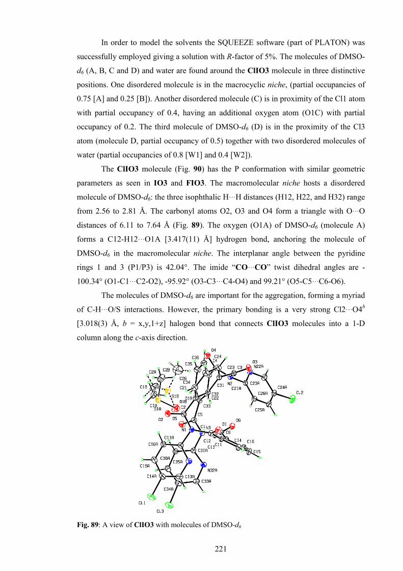
221
In order to model the solvents the SQUEEZE software (part of PLATON) was
successfully employed giving a solution with R-factor of 5%. The molecules of DMSO-
d6 (A, B, C and D) and water are found around the ClIO3 molecule in three distinctive
positions. One disordered molecule is in the macrocyclic niche, (partial occupancies of
0.75 [A] and 0.25 [B]). Another disordered molecule (C) is in proximity of the Cl1 atom
with partial occupancy of 0.4, having an additional oxygen atom (O1C) with partial
occupancy of 0.2. The third molecule of DMSO-d6 (D) is in the proximity of the Cl3
atom (molecule D, partial occupancy of 0.5) together with two disordered molecules of
water (partial occupancies of 0.8 [W1] and 0.4 [W2]).
The ClIO3 molecule (Fig. 90) has the P conformation with similar geometric
parameters as seen in IO3 and FIO3. The macromolecular niche hosts a disordered
molecule of DMSO-d6: the three isophthalic H···H distances (H12, H22, and H32) range
from 2.56 to 2.81 Å. The carbonyl atoms O2, O3 and O4 form a triangle with O···O
distances of 6.11 to 7.64 Å (Fig. 89). The oxygen (O1A) of DMSO-d6 (molecule A)
forms a C12-H12···O1A [3.417(11) Å] hydrogen bond, anchoring the molecule of
DMSO-d6 in the macromolecular niche. The interplanar angle between the pyridine
rings 1 and 3 (P1/P3) is 42.04°. The imide “CO···CO” twist dihedral angles are -
100.34° (O1-C1···C2-O2), -95.92° (O3-C3···C4-O4) and 99.21° (O5-C5···C6-O6).
The molecules of DMSO-d6 are important for the aggregation, forming a myriad
of C-H···O/S interactions. However, the primary bonding is a very strong Cl2···O4b
[3.018(3) Å, b = x,y,1+z] halogen bond that connects ClIO3 molecules into a 1-D
column along the c-axis direction.
Fig. 89: A view of ClIO3 with molecules of DMSO-d6

222
The column is aided by the C2A-H2A3···O6c [C2A···O6c = 3.419(11) Å, c = -
x,y,-1+z ] interaction by which the disordered molecule of DMSO-d6, placed in the
macromolecular niche, links adjacent ClIO3 molecules. Four 1-D columns are
interconnected via Cl3···Cl3a [3.165(3) Å, a = -x,-y,z], C25-H25···N32Ad [C25-
H25···N32Ad = 3.334(7) Å, d = 1/4-x,1/4+y,-3/4+z], Cl1···N22Ae [3.277(4) Å, e = -
1/4+x,1/4-y,-1/4+z] interactions and by disordered DMSO-d6 (C and D) molecules via
C33A-H33A···O1Cb [H33A···O1Cb = 2.56 Å] and C15A-H15A···O1C [H15A···O1C =
2.68 Å] contacts as well as by many other less important contacts.
Fig. 90: ORTEP and CPK diagram of ClIO3 the showing macromolecular niche
The ClIO4 tennimide (Fig. 91) was grown from a mixture of CHCl3, MeOH and
CH2Cl2. Hence, the ClIO4 aggregates with a disordered molecule of either CHCl3 or
CH2Cl2. The ClIO4 molecular structure is more symmetrical than the FIO4, similar to
the 26IO4 structure (Section 5); it consists of two symmetrical halves related by
symmetry code 3/2-x,1/2-y,z. The internal “CO···CO” twist dihedral angles are 102.22°
(O1-C1···C2-O2) and -92.48° (O3-C3···C4-O4). The H···H distances of the intraannular
cavity are 4.365 Å (H12···H12a, a = 3/2-x,1/2-y,z) and 4.091 Å (H22···H22a). The
pyridinyl nitrogen atoms on both sides are in the anti (medial) conformation with a
distance of 3.85 Å (N12A···N12Aa) and 4.3 Å (N12A···N12Aa). Therefore, both sides
(“1” and “2”) of the ClIO4 molecules are in the opened (“oo”) state exposing the
intraannular cavity.
The primary aggregation in ClIO4 crystal structure is formation of “pore-to-
pore” columns along the c-axis direction via C13A-H13A···O3b [C13A-H13A···O3b =

223
3.375(4) Å, b = 3/2-x,y,-1/2+z] hydrogen bonds, aided by weaker C23A-H23A···O1c
[C23A···O1c = 3.487(4) Å, c = 3/2-x,y,1/2+z.] interactions.
Fig. 91: A top-view (a) and a side-view (b) of ClIO4
Each column is surrounded by six other columns, interconnected via C15A-
H15A···O4d [C15A···O4d = 3.209(3) Å, d = 2-x,1-y,-z] and C15-H15···O2e [C15···O2e =
3.461(3) Å, e = 2-x,1-y,-z] hydrogen bonds. The disordered molecule of solvent is
placed between the columns and additionally interconnects them through several
interactions such as O2···Cl2Sf [2.981(5) Å, f = 1+x,1/2-y,-1/2+z] and O1···Cl1Sf
[2.992(6) Å] as well as C16A-H16A···Cl2Sb [C16A···Cl2Sb = 3.541(5) Å] interactions.
8. BrIO3 and BrIO4 macrocycles
8.1. Synthesis and purification
The synthesis and purification of BrIO3/4 was as described for the ClIO3/4
macrocycles (Section 7) with 2-amino-5-bromopyridine (1.6964 g). Chromatographic
separation was accomplished as for the previous halo-substituted macrocycles, yielding
BrIO4 (177.37 mg, 6.0%, Rf = 0.668) and BrIO3 (212.12 mg, 7.14%, Rf = 0. 455). The
resulting material was reasonably pure and no additional preparative TLC was required.
8.2. General and spectroscopic data
Compared with the analogous fluoro and chloro derivatives, the solubility of the
BrIO3 and BrIO4 analogues is generally similar (soluble in CH2Cl2, CHCl3, alcohols,
acetone, THF, ethyl acetate, poorly soluble in diethyl ether and n-hexane, insoluble in
b a

224
water) but lower; especially the BrIO4 tennimide appeared to be significantly less
soluble.
N NH2
Cl
O
Cl
O
TEA, DMAP, CH2Cl2, -15°C, N2
Br
*N
OO
*
N
Br
3/4
Scheme 50: General diagram of the BrIO3/4 synthesis
However, this is as expected, since the starting material (2-amino-5-
bromopyridine) was much less soluble in CH2Cl2 than the chloro and fluoro analogues.
The NMR and IR results (1H- and 13C-NMR data at 80°C are listed in Appendix I,
Sections 4.9 and 4.10, spectra are provided in the ESI III, Sections 1.10 and 1.11) have
confirmed the identity of the compounds and are similar with those of ClIO4 and
ClIO3. The IR data show additional peaks around 3000 cm-1 suggesting that the bulk
BrIO4 is a solvate, but not BrIO3.
8.3. Crystallographic data and discussion
Table 42 presents the basic crystallographic data for the BrIO3 and BrIO4
macrocycles. The BrIO3 trezimide (Fig. 92) crystallises as a solvate in P21/n, with two
BrIO3 molecules in the asymmetric unit and one molecule of ethyl acetate. The ethyl
acetate molecule is not disordered and engages in aggregation.
Table 42: Selected crystallographic dataa for BrIO3 and BrIO4 †
BrIO3 BrIO4
Chemical formula (C39H21Br3N6O6)2·C4H8O2 C52H28Br4N8O8·(CHCl3)0.41
Crystal system,
space group
Monoclinic
P21/n, (No. 14)
Orthorhombic
Pccn, (No. 56)
a, b, c (Å) 10.9531(2) 65.7107(9) 11.2388(2)
14.0441(4) 19.1432(3) 19.1482(4)
α, β, γ (°) 90, 110.454(2), 90 90, 90, 90 Z' 2 1
R[F2 > 2σ(F2)], wR(F2), S 0.0598, 0.1406, 1.14 0.0466, 0.1272, 1.04
† Complete crystallographic, refinement and structural details are listed in the ESI III (Section
2.4). a Obtained with Cu Kα radiation.

225
However, the most interesting feature of BrIO3 is presence of C-Br···O=C
halogen bonds that contribute to crystal structure formation. The two BrIO3 molecules
(A and B) (Fig. 92) are found to be in the P conformation as in most trezimides (except
26IO3) and are geometrically similar. Since the Br2 atoms in both molecules are
disordered, in the molecule A it was assigned as Br2A (0.5) and Br2C (0.5), while in the
molecule B the Br2 atom exists as Br2B [0.61(2)] and Br2D [0.39(2)].
Similarly as with the molecules of DMSO-d6 in the ClIO3 structure, the
molecule of ethyl acetate is located within the macromolecular niche of the BrIO3
molecule A, anchored via C1S-H1S2···O4A [C1S···O4A = 3.302(10) Å] and C16A-
H16A···O1S [C16A···O1S =3.332(10) Å] hydrogen bonds. The macromolecular niches
of the A and B molecules are similar, but slightly different. The three H···H distances
(H12, H22 and H32) in molecule A range from 2.58 to 2.93 Å, and from 2.53 to 2.96 Å
in molecule B. The carbonyl atom (O2, O3 and O4) distances are 6.43 to 7.91 Å in
molecule A and 6.26 to 8.10 Å in molecule B. The interplanar angles between the
pyridine rings (1 and 3, molecule A) are 56.47(18)° and 43.31(22)° (4 and 6, molecule
B). The imide “CO···CO” twist dihedral angles in molecule A are 110.00°, 87.69° and -
99.83°, while in molecule B are -98.39°, -99.31° and 101.81°.
Fig. 92: ORTEP diagrams of BrIO3 (view [a], and side-view [b], only molecule A is shown)
The aggregation in the BrIO3 crystal structure mostly relies on strong C-
H···O=C interactions, however the most interesting are C-Br···O=C halogen bonds such
b a

226
as C64A-Br3B···O6Ba [Br3B···O6Ba = 3.169(4) Å, a = 1/2+x,1/2-y,-1/2+z] and C56A-
Br2B···O1Bb [Br2B···O1Bb = 3.312(6) Å, b = -1+x,y,z]. The first is especially strong
since it is directional [C64A-Br3B···O6Ba angle is 160.20(18)°]. The C-Br···O=C
halogen bonds have been explained in both experimental and theoretical studies.233-236
The strength of this bond comes from contact of a bromine σ-hole233 having
positive electrostatic potential with the electronegative carbonyl oxygen. However, the
main interactions in the BrIO3 crystal structure are numerous C-H···O=C interaction,
such as C54-H54···O1Ac [C54···O1Ac = 3.144(7) Å, c = x,y,1+z], C35A-H35A···O5Ad
[C35A···O5Ad = 3.219(8) Å, d = 1-x,-y,2-z], C15A-H15A···O5Ad [C15A···O5Ad =
3.423(8) Å] and C65A-H65A···O3Be [C65A-H65A···O3Be = 3.202(7) Å, e = x,y,-1+z]
interactions. The solvent, ethyl acetate, does not engage significantly in the aggregation,
in contrast to DMSO-d6 or chlorinated solvent molecules in other macrocycles, apart
from a C4S-H4S3···Br1Af [C4S···Br1Af = 3.654(10) Å, f = 1-x,-y,1-z] interaction.
Other interactions are C-H···π contacts such as C24-H24···C5B [C24···C5B = 3.577(7)
Å], C=O…π contacts such as C2B-O2B···C23A [O2B···C23A = 3.118(7) Å] and a
myriad of C-Br…π contacts, the strongest being the C54A-Br2D···C63Ag
[Br2D···C63Ag = 3.195(18) Å, g = -1/2+x,1/2-y,1/2+z] interaction.
The BrIO4 tennimide (Fig. 93) is essentially isomorphous with ClIO4, although
the cell dimensions are slightly longer. It crystallises with a molecule of CHCl3 that has
a partial occupancy of 0.82 and is disordered about a rotation axis (1/2-x,1/2-y,z). As
seen in ClIO4 and 26IO4 the molecular structure of BrIO4 is symmetric and consists
of two equivalent halves about the rotation axis (1/2-x,1/2-y,z). However, and
differently to ClIO4, the molecule of BrIO4 has the “2” bromo-pyridinyl rings
disordered about the Br24···N2 axis, with 63% of the ring being in syn (lateral, part A)
and 37% being in anti (medial, part B) conformation. The cause of disorder is a partial
hydrogen bond between the N22A atom and the solvent hydrogen atom, C1S-
H1S···N22Aa [C1S-H1S···N22Aa = 3.43(2) Å, a = 1/2-x,1/2-y,z]. If this hydrogen bond
is fully established, a very repulsive and unfavourable H26A···H26Aa (1.90 Å) contact
emerges. Therefore, the disorder of the “2” bromo-pyridinyl rings is caused by a
balance between the stabilising, favourable C1S-H1S···N22Aa hydrogen bond and
destabilising steric clash H26A···H26Aa.
In general, the BrIO4 molecule is symmetrical; the intraannular cavity distances
(H···H) are 4.128 Å (H12···H12a) and 4.352 Å (H22···H22a). The internal “CO···CO”
twist dihedral angles are 94.33° (O1-C1···C2-O2) and -103.78° (O3-C3···C4-O4). The
bromo-pyridinyl ring “1” is in the syn conformation (lateral) with a H16···H16a distance

227
of 2.65 Å; hence the pore is closed. In total, the pores are 63% in “cc” state and 37% in
the “oc” state.
Fig. 93: ORTEP and CPK diagrams of the BrIO4 tennimide
The aggregation in BrIO4 is similar to the aggregation in ClIO4. The molecules
are “pore-to-pore” lined up along the c-axis direction into a 1-D column via strong
C25A-H25A···O1b [C25A···O1b = 3.329(9) Å, b = 1/2-x,y,1/2+z] hydrogen bonds. The
columns are interconnected by a C25B-H25B···O2c [C25B···O2c = 3.09(2) Å, c = -x,1-
y,-z] hydrogen bond and weaker C25-H25···O4d [C25···O4d = 3.514(5) Å, d = -x,-y,-z]
and C23A-H23A···O2c [C23A···O2c = 3.373(16) Å] interactions. The aggregation is
aided by the disordered CHCl3 molecule through the partial C1S-H1S···N22Aa
hydrogen bond, as well as by Cl3S···O4e [3.077(5) Å, e = 1+x,y,z] and Cl2S···O3a
[3.126(8) Å] halogen bonds. In contrast with the BrIO3 crystal structure, no C-
Br···O=C halogen bond is present, although a weak C14A-Br14···Cl2Sf [Br14···Cl2S =
3.516(6) Å, f = 3/2-x,y,-1/2+z] halogen contact exists.
9. 26BrIO3 and 26BrIO4 macrocycles
9.1. Synthesis and purification
The 26BrIO3/4 macrocycles were synthesised (Scheme 51) and purified using
identical procedures as described for the BrIO3/4 macrocycles (Section 8) with 2-
amino-5-bromopyrimidine (1.7053 g, 9.8 mmol) instead of 2-amino-5-bromopyridine.
The 2-amino-5-bromopyrimidine was quite insoluble in dry CH2Cl2, even upon heating,

228
and was added into the reaction mixture in the form of a suspension. The result was
26BrIO3 (164.4 mg, 5.5%, Rf = 0.472) and 26BrIO4 (110.0 mg, 3.67%, Rf = 0.607).
N
N
NH2
Cl
O
Cl
O
TEA, DMAP, CH2Cl2, -15°C, N2
Br
*N
OO
*
NN
Br
3/4
Scheme 51: General diagram of the 26BrIO3/4 synthesis
9.2. General and spectroscopic data
The 26BrIO3/4 macrocycles proved to be the most insoluble. However,
26BrIO3 was significantly more soluble than 26BrIO4 that proved to be very insoluble
in most organic solvents, even in warm DMSO. Hence, the NMR characterisation of
26BrIO4 was accomplished in DMSO-d6 at 140°C. Unfortunately, such a high
temperature caused partial disintegration of the compound. The 1H-NMR with variable
temperature procedure was undertaken from the highest towards the lowest temperature.
All the spectroscopic information including NMR and IR is listed in Appendix I
(Sections 1.12 and 1.13) and the spectra are given in the ESI III (Sections 1.12 and
1.13).
9.3. Crystallographic data and discussion
Table 43 summarises the basic crystallographic data of the 26BrIO3/4
macrocycles. The 26BrIO3 trezimide (Fig. 94) crystallises as a solvate with two
molecules of CH2Cl2, one (molecule “1”) and another disordered as molecule “2” (0.75)
and “3” (0.25). The CH2Cl2 molecule plays important an role in the aggregation of the
26BrIO3 trezimide, in contrast with the disordered molecule.
The 26BrIO3 molecule (Fig. 94) is in the typical P conformation, in contrast
with the parent 26IO3 trezimide that was found in the R conformation (Section 5). The
geometric parameters are as expected: the three H···H distances (H12, H22 and H32)
range from 2.48 to 3.02 Å, the carbonyl atoms O···O distances (O2, O4 and O4) range
from 6.44 to 8.12 Å, while the interplanar angle between the pyridine rings 1 and 3

229
(P1/P3) is 41.88(15)°.The imide “CO···CO” twists are -94.73° (O1-C1···C2-O2), -
86.58° (O3-C3···C4-O4) and 95.55° (O5-C5···C6-O6).
Table 43: Selected crystallographic data for the 26BrIO3 and 26BrIO4 macrocycles†
26BrIO3 26BrIO4
Chemical formula C36H18Br3N9O6·(CH2Cl2)2 (C48H24Br4N12O8)2·(CHCl3)3.8·H2O
Crystal system, space group
Triclinic, P ̅1, (No. 2)
Monoclinic
P21/n, (No. 14)
a, b, c (Å) 12.2390(5), 13.6149(5), 13.6447(5)
10.5779(3), 13.2805(3), 40.7855(13)
α, β, γ (°) 100.749(3), 99.990(3), 95.463(3)
90, 95.936(2), 90
Z' 1 1 R[F2 > 2σ(F2)], wR(F2), S 0.0667, 0.1877, 1.02 0.0763, 0.2053, 1.03
† Complete crystallographic, refinement and structural details are listed in the ESI III (Section
2.4).
The most important and strongest interaction in the 26BrIO3 structure is a
strong C14A-Br14···O4a [Br14···O4a = 2.982(3) Å, a = x,y,z-1] halogen bond.237 As
mentioned in the previous section, the strength comes from a direct contact [168.2(2)°]
of a positive σ-hole with the electronegative carbonyl oxygen. This halogen bond links
the 26BrIO3 molecules along the c-axis direction into a 1-D column.
Fig. 94: An ORTEP diagram of 26BrIO3 and solvent molecules

230
Two columns are interconnected via the non-disordered CH2Cl2 molecule (“1”)
by C1S-H1S1···N16Ab [C1S···N16Ab = 3.262(9) Å, b = -x,-y,1-z] and C1S-H1S2···O5
[C1S···O5 = 3.435(10) Å] interactions, aided by the C35-H35···O4c [C35···O4c =
3.427(5) Å, c = -x,-y,2-z] interaction. The C15-H15···O3d [C15···O3d = 3.235(7) Å, d =
1-x,1-y,2-z] and C14-H14···O3d [C15···O3d = 3.248(6) Å] interactions connect the
column pairs into a 2-D sheet. Finally, a strong C25-H25···O4e [C35···O4e = 3.271(6)
Å, e = 1-x,-y,2-z] interaction, with support of the C-Br···π interactions such as C24A-
Br24···C34f [Br24···C34f = 3.395(5) Å, f = -x,1-y,2-z] and C24A-Br24···C35f
[Br24···C35f = 3.362(5) Å] contacts aggregates 2-D sheets into a crystal structure.
The 26BrIO4 molecule (Fig. 95) was grown from CHCl3 and crystallised with
two molecules of CHCl3 and a molecule of H2O. The first CHCl3 molecule (“S”) is
located in proximity of the O1 atom, shows no disorder but has partial occupancy of 0.9,
while the second CHCl3 molecule (“T”) is in proximity of the O6 carbonyl atom, shows
disorder (1T = 0.7, 2T = 0.3), but has total occupancy of 1. The H2O molecule is located
beside the pore entrance close to the “B” bromo-pyrimidine ring and has partial
occupancy of 0.5. The solvent molecules form many strong interactions with the
26BrIO4 molecules that largely contribute to crystal aggregation and stability, but are
not crucial. However, the high quality of 26BrIO4 single crystals is due to the presence
of solvent molecules in its crystal structure.
The 26BrIO4 molecule is less symmetrical, as in the IO4 and FIO4 crystal
structures and the structural parameters are different for each segment. The imide
'CO···CO' twist torsion angles are 86.66° (O1-C1···C2-O2), -101.25° (O3-C3···C4-O4),
101.95° (O5-C5···C6-O6) and -97.22° (O7-C7···C8-O8). The intraannular cavity
(H···H) distances are 4.061 Å (H12···H32) and 4.199 Å (H22…H42a). The distances
between the medial pyrimidine nitrogen atoms are 4.467 Å (N12B···H12D) and 4.564 Å
(H12A···H12C). Therefore, the pores are in the “oo” state.
Intermolecular interactions in the 26BrIO4 crystal structure, due to the presence
of both CHCl3 and H2O molecules are numerous and include a myriad of C-H…O
interactions, hydrogen and halogen bonds. The interactions formed by the solvent
molecules are stabilising, but are not crucial for the aggregation, since the 26BrIO4
crystal structure mainly relies on interactions formed by the 26BrIO4 molecules
themselves.
The major interactions are C13D-H13D···O5a [C13D···O5a = 3.197(8) Å, a = -
1+x,y,z] and C34-H34···O3b [C34···O3b = 3.288(7) Å, b = 1+x,y,z] hydrogen bonds that
aggregate the 26BrIO4 molecules along the a-axis direction in a “pore-to-pore” manner

231
into a 1-D column. The columns are interconnected along the b-axis direction into a 2-D
sheet parallel with (001) plane via a strong C14B-Br1B···N16Ac [Br1B···N16Ac =
3.028(4) Å, c = x,1+y,z] halogen bond.
Fig. 95: A view of the 26BrIO4 tennimide
This halogen bond is similar to the C-Br···O=C bond found in the BrIO3 and
26BrIO3 crystal structures. Two adjacent sheets are interconnected by C15A-
H15A···O4d [C15A···O4d = 3.356(7) Å, d = -x,1-y,-z] hydrogen bonds, supported by
weak C-Br···π contacts C14A-Br1A···C24d [Br1A···C24d = 3.482(6) Å]. Finally, the
pairs of sheets aggregate into a 3-D crystal structure via lateral multiple interactions of
the O8 carbonyl oxygen with the isophthalic ring “1” such as C14-H14···O8e [C14···O8e
= 3.114(6) Å, e = 1/2-x,-1/2+y,1/2-z] and C15-H15···O8e [C15···O8e = 3.174(7) Å]
interactions. The CHCl3 and H2O solvent molecules form an additional supporting
network of interactions.
10. MIO4 macrocycle
10.1. Synthesis and purification
The MIO4 tennimide (Figs. 97 and 97) was synthesised using the standardised
“4+4” method (Section 2.3), with 2-amino-5-methylpyridine (6-amino-3-picolinate,
1.0600 g, 9.8 mmol), (Scheme 52). The crude product was purified by column

232
chromatography eluting with a solvent blend of CHCl3 and ethyl acetate (2:1). Although
an additional compound was detected by TLC (possible trezimide, MIO3) only
separation of the first fraction was successful (MIO4, 110 mg, 5%, Rf = 0.270).
N NH2
Cl
O
Cl
O
TEA, DMAP, CH2Cl2, -15°C, N2
H3C
*N
OO
*
N
CH3
4
Scheme 52: General diagram of the MIO4 synthesis
10.2. General and spectroscopic data
The MIO4 tennimide is a white, moderately crystalline solid, readily soluble in
chlorinated hydrocarbons (CHCl3, CH2Cl2), ethyl acetate and MeOH, less soluble in
diethyl ether and insoluble in water and n-hexane.
The 1H-NMR experiments in DMSO-d6 at 80°C (Appendix I, Section 4.13 and
the ESI III, section 1.14) shows good resolving of the core tennimide proton peaks. The
methyl peak is at 2 ppm, while the 13C-NMR (same conditions) shows the methyl
carbon at 17.25 ppm. No evidence of instability was detected by the NMR experiments,
suggesting overall stability of the MIO4 tennimide being comparable with the parent
IO4 tennimide.
10.3. Crystallographic data and discussion
The MIO4 tennimide (Table 44, Figs. 97 and 97) crystallises as a solvate with one
disordered molecule of CH2Cl2.
Table 44: Selected crystallographic data for the MIO4a macrocycle†
Chemical formula C56H40N8O8.CH2Cl2 Crystal system, space group Orthorhombic, Pccn, (No. 56) a, b, c (Å) 13.9556(3) 19.0850(4) 19.1230(3) α, β, γ (°) 90, 90, 90 Z' 1 R[F2 > 2σ(F2)], wR(F2), S 0.0666, 0.1628, 1.0 † Complete crystallographic, refinement and structural details are listed in the ESI III (Section
2.5). aObtained with Cu Kα radiation.

233
Fig. 96: An ORTEP diagram of the MIO4 structure
Similar to the 26IO4, ClIO4 and BrIO4 tennimides, the MIO4 tennimide
molecule is symmetrical and consists of two halves related by symmetry code 1/2-x,1/2-
y,z. Dihedral angles of the internal imide 'CO···CO' twist are 101.12° (O1-C1···C2-O2)
and -92.15° (O3-C3···C4-O4). The intraannular cavity H···H distances are 4.361 Å
(H12···H12a, a = 1/2-x,1/2-y,z) and 4.152Å (H22···H22a). Two pyridinyl rings (N12A,
N12Aa) are in the medial conformation (P-anti) with distance of 3.84 Å, while the two
pyridinyl nitrogen on the opposite side (N22A) are in (P-syn) lateral conformation,
exposing the two H26A hydrogen atoms medially (H26A···H26Aa = 2.564 Å).
Therefore, it seems that side 2 has wider pore than side 1 (“oc” state). The methyl
moieties are disordered about the C-C axis by 60°.
Fig. 97: An ORTEP diagram of MIO4 viewed down b-axis

234
Aggregation in MIO4 involves a disordered molecule of solvent (CH2Cl2). The
MIO4 and solvent molecule are connected by multiple contacts such as Cl2S···O2
[3.038(7) Å] and C16A-H16A···C1S [C16A···C1S = 3.51(2) Å], and arranged into a 1-
D column along the a-axis via Cl1S···O1b [3.135(6) Å, b = 3/2-x,1/2-y,z] and C16A-
H16A···Cl2Sb [C16A···Cl2Sb = Å] interactions. Another interaction is C15A-
H15A···O4d [C15A···O4d = 3.249(5) Å, d = 1-x,1-y,1-z] hydrogen bond that links the 1-
D columns along the ( ̅110) plane direction into a wavy 2-D sheet, parallel with the (101)
plane.
11. EsIO3 and EsIO4 macrocycles
11.1. Synthesis and purification
The EsIO3 and EsIO4 molecules were synthesised using the standard “4+4”
synthetic procedure described in Section 2.3 (Scheme 53). The methyl-6-
aminopyridine-3-carboxylate (1 g, 6.57 mmol), having a COOCH3 moiety in the para
position of the 2-AP ring, was used. Chromatographic purification and separation of the
macrocycles was accomplished using CHCl3/ethyl acetate (1:1) as an appropriate
mobile phase system. The result was pure EsIO3 (300 mg, 16%, Rf = 0.60) and EsIO4
(156.5 mg, 9%, Rf = 0.33) macrocycles.
N NH2
Cl
O
Cl
O
TEA, DMAP, CH2Cl2, -15°C, N2
O
OH3C
*N
OO
*
N
OO
CH3
3/4
Scheme 53: Synthesis of the EsIO3 and EsIO4 macrocycles
11.2. General and spectroscopic data
The EsIO3 and EsIO4 macrocycles are white odourless substances, insoluble in
water and readily soluble in most organic solvents apart from n-hexane and diethyl
ether.

235
The NMR and IR spectral data are listed in Appendix I, sections 4.14 and 4.15,
while the spectra are provided in the ESI III, Sections 1.15 and 1.16. Due to
conformational rigidity in solution at the room temperature, the 1H-NMR experiment of
EsIO4 at 20°C in CDCl3 failed to show sufficiently resolved peaks and appropriate
integration. The 13C-NMR and HSQC experiments failed to show the C14 peak clearly
as well as C1 in DEPT and DEPT-Q. The variable temperature 1H-NMR in DMSO-d6
raising the temperature from 20°C to 80°C improved the conformational
interconversion rate and peaks were gradually resolved. Problems seen in CDCl3 at
20°C were overcome with the corresponding experiments in DMSO-d6 at 80°C.
However, heating of EsIO3 in DMSO-d6 caused disintegration suggesting its relative
instability. Therefore, variable temperature 1H-NMR and the corresponding experiments
in DMSO-d6 at 80°C didn’t prove useful. However, NMR experiments in CDCl3 at
20°C gave good peak separation as well as coupling, suggesting conformational
mobility in solvent.
The IR spectra show very strong bands around 1720-1690 cm-1 corresponding
with both imide and ester carbonyl (C=O) stretches. The peaks at 1600-1400 cm-1 are
associated with C-C and C-N vibrations in isophthalic and pyridinyl rings while the
strong peaks in 1400-1200 cm-1 region belong to C-N and C-C vibrations and stretches
in imide backbone.
11.3. Crystallographic data and discussion
Table 45 summarises the key crystallographic data for EsIO3 and EsIO4.
Crystals of EsIO3 were obtained as poor-quality lathes from diethyl ether/n-hexane
mixtures (though suitable for study by single crystal X-ray diffraction) whereas crystals
of EsIO4 were grown as long needles from CHCl3/MeOH solutions.
Table 45: Selected crystallographic data for EsIO3 and EsIO4 †
EsIO3a EsIO4
Chemical formula C45H30N6O12 C60H40N8O16 Crystal system, space group
Triclinic, P̅1 (No. 2)
Monoclinic, P21/n (No.14)
a, b, c (Å) 16.3411(13), 16.5747(4), 17.4806(16)
10.6870(1), 22.4852(2), 22.6756(2)
α, β, γ (°) 87.273(5), 83.350(7), 89.825(4) 90, 101.721(1), 90
Z' 2 1
R[F2 > 2σ(F2)], wR(F2), S 0.121, 0.352, 0.91 0.041, 0.120, 1.02

236
† Complete crystallographic, refinement and structural details are listed in the ESI III (Section
2.5). a Obtained with Cu Kα radiation.
The crystal structures of EsIO3 (Fig. 98) and EsIO4 (Fig. 99) show several
unique features. The EsIO3 structure (Z' = 2) crystallises in the triclinic system (P ̅1)
with small but significant differences between the two molecules (molecule A is
depicted) both in the P conformation. The three isophthalic H···H distances (H12, H22
and H32) range from 2.64 to 2.80 Å, whereas the carbonyl O…O distances (O2A, O3A
and O5A) are from 5.76 to 7.92 Å (in molecule A, Fig. 98).
Two pyridine groups at N1 and N3 adopt parallel orientations with their ortho-N
ring atoms N12A, N32A positioned syn at a distance of 4.89 Å, and with their methyl
carboxylates at contact distances. The imide “CO···CO” twists in molecule A are
95.45° (O1-C1···C2-O2), -111.30° (O3-C3···C4-O4) and -91.92° (O5-C5···C6-O6).
The EsIO3 trezimide, as an acceptor rich system comprising nine 9 C=O, three
pyridine and methoxy acceptor groups (neglecting the three tertiary N1-N3 atoms that
are oriented towards the macrocycle niche); molecular aggregation is dominated by the
cumulative effect of several weak C-H···O interactions such as C35A-H35A···O31Aa
[C35A···O31Aa = 3.204(13) Å, a = 1-x,1-y,2-z] and C65A-H65A···O61Ab
[C65A···O61Ab = 3.227(14) Å, b = 2-x,-y,-z] and C55-H55···O3A [C55···O3A =
3.377(14) Å].
Fig. 98: a) space-filling and b) ORTEP diagrams of EsIO3 (molecule A)
Crystals of EsIO3 grow as very fragile thin lathes that diffracted very weakly.
a b

237
The first attempt (Mo radiation) gave a unit cell and diffraction data only to 2.5 Å
resolution, whereas a second data collection gave reflection data to a 1.5 Å resolution
limit [data were collected to 0.94 Å with Cu Kα radiation, 1° ω-scans, the detector at
60mm and with three shells collected for 16s/48s/48s per frame]. This dataset was not
sufficient to produce a structural solution (data redundancy were 1.7, F2 = 2.1 and Rint =
0.16). Finally, on a third attempt, using Cu radiation at 40 kV/40 mA over 72 hours,
reflection data were collected to a diffraction limit of 1.35 Å, with frames to 1.00 Å
with 0.5° scans, shells collected for 24s/48s per frame and the detector at 60 mm (data
redundancy = 1.8, F2 = 4.3 and Rint = 0.083). This enabled a structural solution from a
moderate direct methods attempt. It was apparent at an intermediate stage of refinement
that there were considerable voids in the lattice amounting to 21% of the unit cell and
containing solvent molecules of unknown composition and occupancy. The program
SQUEEZE169 was used and the R-factor dropped from 18% to 12% after using this
program. The refinement proceeded without any problems or use of restraints to give a
satisfactory EsIO3 structure (with Z' = 2). There are small but significant differences
between the two molecules A and B in the asymmetric unit. Crystals of EsIO3 can be
grown from acetonitrile (CH3CN) solutions to produce colourless plates; however these
decompose rapidly when handled (using several inert handling conditions) and we were
able to observe diffraction and obtain a unit cell of one of these crystals: a =11.89(2) Å,
b = 12.24(2) Å, c = 18.77(2) Å, α = 86.38(13)°, β = 78.71(14)°, γ = 65.49(16)°, Volume
= 2439(7) Å 3 which is consistent with triclinic (Z’ = 2) and an indeterminate solvent
composition in the lattice voids.
Fig. 99: a) ORTEP and b) space-filling diagrams of EsIO4

238
The EsIO4 structure (Fig. 99), contrary to most of the tennimides and trezimides
was not isolated as solvate. The EsIO4 macrocyclic cavity is compact with H···H intra-
annular distances across the cavity of 4.13 and 4.18 Å. The internal amide “CO···CO”
twist angles are 113.01° (O1-C1···C2-O2), -112.52° (O3-C3···C4-O4), 94.33° (O5-
C5···C6-O6) and -88.90° (O7-C7···C8-O8). The pyridine rings are in the P-syn (lateral,
rings “1” and “4”) and P-anti (medial, rings “2” and “3”) conformations as in IO4, with
distances between the medial pyridine nitrogen and hydrogen atoms of 3.191 Å
(N12A···H16A) and 3.308 Å (N22A···H46A), Hence, the pores are in “cc” state. The
methyl ester COOCH3 moieties are co-planar with the pyridine rings. Due to the
presence of many carbonyl and methyl moieties the aggregation in the EsIO4 crystal
structure relies on a myriad of C-H···O interactions.
An overview of the tennimides and trezimides results is presented in the
“Discussion and Conclusions”.

239
DISCUSSION AND CONCLUSIONS

240
1. Benzamides and pyridinecarboxamides
The design of new materials continues unabated with a preoccupancy to
maximise distinct physicochemical properties e.g. fluorescence, with thermal stability
and melting point behaviour regarded as a relatively unimportant physical characteristic.
Even though an enormous quantity of melting point data is available in the chemical
literature and from databases, the prediction of melting points of organic compounds
remains difficult though correlations of classes of organic compound have provided
some distinct trends.238
The melting point results (Table 46) for 4 × [3 × 3] series of Mxx, NxxM, NxxF
and Fxx isomers demonstrate that trends previously noted in di-substituted benzenes11,
239 for meta- < ortho- < para-substitution show similar patterns, but with distinct
combinations producing both the highest and lowest melting point ranges. Melting point
differences between 62 and 112°C are observed between the highest and lowest mp's in
the four benzamide and pyridinecarboxamide isomer grids (depicted with ♦ and *). The
results suggest that proper consideration has to be given to the thermal stability and
behaviour of closely related aromatic isomers and especially if they are combinations of
di-substituted aromatics (as found in many materials). While melting point behaviour
depends on many factors the following trends are clear.
There is a decrease in average melting point from the symmetrical pp (para-
para) compounds to the F/Mmo compounds of the F/Mxx series and two NomF/M
derivatives in the NxxM/F series.
Table 46: Melting pointsa for Mxx, NxxM, NxxF and Fxx isomer grids.c
Mxx Mp Mm Mo No Nm Np NxxM p 181♦ 106 129 105 148 162
♦ pM
m 128 91 108 50* 115 142 mM o 105 79* 116 65 107 125 oM o 120 77* 85 107 117 140♦ oF m 150, 148 151 89 78* 122 132 mF p 187♦ 186 135 94 133 135 pF Fxxb Fp Fm Fo No Nm Np NxxF a Average melting point range for all 36 compounds with highest denoted by ♦ and lowest by *.
These four F/Mmo and NomF/M compounds possess an ortho-pyridine C5N
ring N atom in combination with a C6 aromatic ring meta-F/CH3 substituent. The trend
follows Carnelly's rule.239 Of note is that the four compounds with oo substituents have

241
higher melting points by ca. 20°C with a range of 65 to 116°C, (average of 93°C) as
compared to the four mo/om derivatives 60 to 79°C (average of 71°C).
Comparisons between the Fxx (131°C mp average) and Mxx (116°C) series
with NxxF (117°C) and NxxM (113°C) series demonstrates that the average melting
points are remarkably similar (except for Fxx) although the ranges and order of melting
point trends are unique within each of the four series.
The average para-isomer has a melting point of 137°C, the average meta-isomer
115°C and the average ortho-isomer 102°C and averaged over the 20 of 36 isomers
which contain each p-/m-/o-substituent. This helps explain why the overall melting
point trend is p > m > o but not the observed substitution pattern whereby the mo/om
combination have the lowest melting points.
Table 47 summarises the salient features of all thirty six Mxx, Fxx, NxxM and
NxxF benzamide/pyridinecarboxamide isomer grids and the two additional polymorphs.
The table contains crystallographic and solid state results (space group, Z/Z', primary
interaction, solid-state conformation), modelling data (gas phase conformation) and 1H-
NMR (amide N-H shift, CDCl3).
Although benzamides and pyridinecarboxamides are not, strictly speaking,
congeners, they have, sharing similar moieties, a high level of similarity (apart from the
reversed amide bridge) that facilitates comparisons. The most common crystal system is
monoclinic with 23 (61%) of all crystal structures (38) with most frequent space group
P21/c or P21/n (10). The space group Cc is represented by (NpoM, NpmF, NpoF), P21
(Fom_O and NomM), P2/c (NppM) and Pc (Mop). The triclinic system is also
prevalent (10), with P ̅1 as the most frequent (9) and Mpm in P1. The triclinic system is
more prevalent in F/Mxx benzamides than the NxxF/M pyridinecarboxamides and
especially for Mxx. The orthorhombic crystal system is less abundant, with five
structures in four space groups, Pca21 (Mom, Fmm) P212121 (NmoF), Pbca (NmoM)
and Pbcn (Fpo).
The primary hydrogen bonding in the crystal structures of all 38 isomers can be
analysed in four groups. The most common interaction is the amideN-H···Npyridine as zig-
zag chains in 18 structures. This usually arises in molecules where the pyridine N atom
is positioned as para- or meta- and while having N as para- makes the N-H···N
convenient, isomers with meta-N usually have to have their P or N rings in a meta-
stable anti conformation.

242
Table 47: Summary list of four isomer grids with selected structural features
Isomer Space group
Z/Z' Hydrogen bonding in solid state
Conformation (solid state)
Conformation (gas phase)
Match Amide H shift (CDCl3) /ppm
Mpp P21/n 4/1 N-H···N ─ ─ ─1 8.30 Mmp P̅1 4/2 N-H···N M-syn M-anti ���� 8.25 Mop Pc 4/2 N-H···N M-syn|M-anti M-anti ����/����2 8.23 Mpm P1 4/4 N-H···O=C P-syn P-syn ���� 8.11 Mmm P̅1 4/2 N-H···N M-anti/P-anti M-anti/P-syn ���� 8.16 Mom Pca21 4/1 N-H···N M-anti/P-anti M-anti/P-syn ���� 7.98 Mpo P̅1 2/1 (N-H···N)2 P-syn P-syn ���� 8.70 Mmo P21/c 4/1 (N-H···N)2 M-anti/P-syn M-anti/P-syn ���� 8.78 Moo P̅1 2/1 (N-H···N)2 M-syn/P-syn M-anti/P-syn ���� 8.99 Fpp P21/c 4/1 N-H···N ─ ─ ─1 8.01 Fmp P21/c 4/1 N-H···N F-anti F-anti ���� 8.01 Fop P21/c 4/1 N-H···N F-syn F-syn ���� 8.68 Fpm_O P21/n 4/1 N-H···O=C P-syn P-syn ���� 8.56 Fpm_N P21/n 4/1 N-H···N P-anti P-syn ���� 8.56 Fmm Pca21 4/1 N-H···N F-anti/P-anti F-anti/P-syn ���� 8.45 Fom_O P21 12/6 N-H···O=C F-syn/P-syn|anti F-syn/P-syn ����/����3 8.53 Fom_F P21/n 4/1 N-H···O=C F-syn/P-anti F-syn/P-syn ���� 8.53 Fpo Pbcn 8/1 (N-H···N)2 P-syn P-syn ���� 9.04 Fmo P̅1 4/2 (N-H···N)2 F-anti/P-syn F-anti/P-syn ���� 8.75 Foo P̅1 4/2 (N-H···N)2 F-syn/P-syn F-syn/P-syn ���� 9.03 NppM P2/c 4/1 N-H···O=C ─ ─ ─1 8.00 NpmM P21/n 4/1 N-H···N M-anti M-anti ���� 7.96 NpoM Cc 4/1 N-H···O=C M-syn M-syn ���� 7.90 NmpM P21/c 4/1 (N-H···N)cat4 N-syn N-syn ���� 8.22 NmmM P̅1 4/2 N-H···N N-anti/M-anti N-syn/M-anti ���� 8.26 NmoM Pbca 8/1 N-H···O=C N-anti/M-anti N-syn/M-syn ���� 7.81 NopM P21/c 4/1 (N-H···N)i N-syn N-syn ���� 9.90 NomM P21 4/2 N-H···O=C N-syn/M-anti N-syn/M-anti ���� 9.94 NooM P21/c 4/1 (N-H···N)i N-syn/M-syn N-syn/M-syn ���� 10.03 NppF P̅1 4/2 N-H···O=C ─ ─ ─1 7.91 NpmF Cc 4/1 N-H···N F-syn F-anti ���� 8.03 NpoF Cc 4/1 N-H···N F-anti 5 F-syn ���� 8.15 NmpF P̅1 8/4 (N-H···N)4
6 N-syn N-syn ���� 8.44 NmmF P21/n 4/1 N-H···N N-anti/ F-anti N-syn/F-anti ���� 8.75 NmoF P212121 4/1 N-H···N N-syn/F-syn N-syn/F-syn ���� 8.23 NopF P21/c 4/1 (N-H···N)i N-syn N-syn ���� 10.04 NomF P21/n 8/2 (N-H···N)i N-syn/F-anti
7 N-syn/F-anti ���� 10.13 NooF P21/n 4/1 (N-H···N)i N-syn/F-syn N-syn/F-syn ���� 10.36 Notes: 1 ─ non-applicable (N/A); 2 Mop crystallises with two molecules in asymmetric unit,
each with different M-ring conformation; 3 Fom_O polymorph has one of six molecules in the
F-syn/P-anti conformation; 4 NmpM forms catemers; 5 minor component only in F-syn
conformation; 6 NmpF forms tetramers; 7 with only 3% as F-syn.
This is the case with all 'XmmX' compounds as well as the Fpm_N polymorph.
Exceptions include the tetrameric NmpF, catemeric NmpM, mixed methyl/fluoro
system NmpFM) and NmoF. A second group comprising 9 structures has the less

243
common N-H···O=C hydrogen bonding with C(4) chains and is present in some
NxxF/M isomers such as NppF, NppM, NpoM, and NmoM. The Mpm isomer and
Fpm_O aggregate by N-H···O=C interactions having similar structures, as well as
Fom_O (P-syn) and Fom_F (P-anti). The NomM structure forms N-H···O=C
hydrogen bonds unexpectedly, however, the presence of an intramolecular (N-H···N)i
interaction hampers the stability of the N-H···O=C hydrogen bond. NomM has a low
melting point (50°C) with difficulty in getting diffraction quality crystals. The third
group comprises the six Mxo and Fxo isomers where the pyridine N atom is located
ortho so that it has a unique role in dimer formation. Two N-H···N interactions form a
R2
2(8) ring by the perfect match of Mxo molecular pairs, less so for Fxo. This is
labelled in Table 29 as (N-H···N)2 and is similar to the hydrogen bonded (RCOOH)2
carboxylic acid dimers observed in centrosymmetric carboxylic acids. The Mxo and
Fxo solid state and modelled conformations almost always match except for Moo where
the Mo ring rotates in order to accomplish the important and short C-H···π(arene)
interaction. The ortho nitrogen also causes an additional acidity of the amide hydrogen
as can be observed in the 1H-NMR as a small additional deshielding effect (higher
values of chemical shifts). The fourth group comprises the NoxM and NoxF isomers.
Here the pyridine nitrogen is positioned ortho-, however, due to the amide linkage
reversal, the amide hydrogen is now directed towards the pyridine N atom, facilitating
the formation of intramolecular N-H···N hydrogen bonding designated by (N-H···N)i.
The weakening of the amide hydrogen is noted in additional deshielding in the 1H-NMR
(CDCl3). In NooF the additional N-H···F interaction additionally deshields the amide
hydrogen ensuring its chemical shift is the lowest for all isomers (at 10.36 ppm).
The type of hydrogen bonding can also be detected using IR spectroscopy. The
presence of N-H···N interactions gives a diffuse pattern of weak peaks ranging from
3400 to 2800 cm-1 whereas N-H···O=C hydrogen bonding is noted by a sharp peak ca.
3300 cm-1. The cyclic (N-H···N)2 hydrogen bonding has a typical complex of elevated
and merged medium peaks ranging from 3100 to 2900 cm-1. Finally, isomers with (N-
H···N)i hydrogen bonding have a very strong and sharp peak ca. 3330 cm-1. It is
interesting that in the unusual NomM isomer where both N-H···O=C and (N-H···N)i
hydrogen bonding occurs the relevant N-H (at 3286 cm-1) and C=O (at 1700 cm-1)
stretching vibrations are positioned at lower wavenumbers.
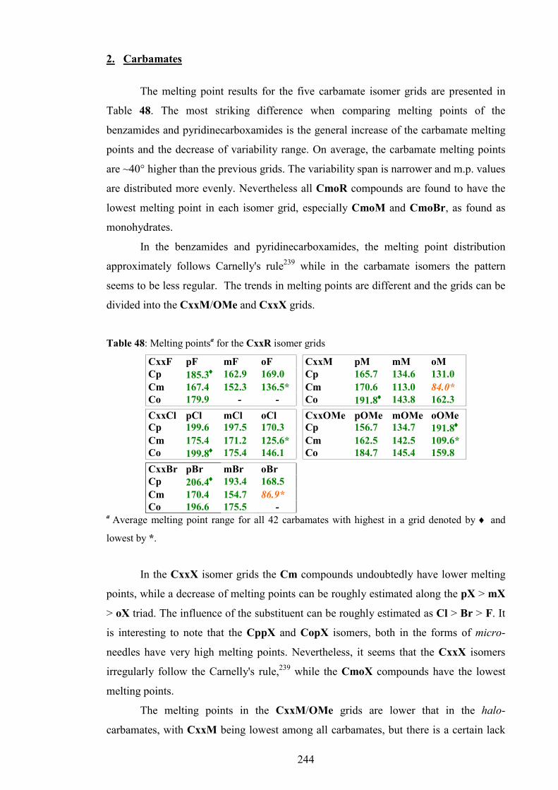
244
2. Carbamates
The melting point results for the five carbamate isomer grids are presented in
Table 48. The most striking difference when comparing melting points of the
benzamides and pyridinecarboxamides is the general increase of the carbamate melting
points and the decrease of variability range. On average, the carbamate melting points
are ~40° higher than the previous grids. The variability span is narrower and m.p. values
are distributed more evenly. Nevertheless all CmoR compounds are found to have the
lowest melting point in each isomer grid, especially CmoM and CmoBr, as found as
monohydrates.
In the benzamides and pyridinecarboxamides, the melting point distribution
approximately follows Carnelly's rule239 while in the carbamate isomers the pattern
seems to be less regular. The trends in melting points are different and the grids can be
divided into the CxxM/OMe and CxxX grids.
Table 48: Melting pointsa for the CxxR isomer grids
CxxF pF mF oF CxxM pM mM oM
Cp 185.3♦♦♦♦ 162.9 169.0 Cp 165.7 134.6 131.0
Cm 167.4 152.3 136.5* Cm 170.6 113.0 84.0*
Co 179.9 - - Co 191.8♦♦♦♦ 143.8 162.3
CxxCl pCl mCl oCl CxxOMe pOMe mOMe oOMe Cp 199.6 197.5 170.3 Cp 156.7 134.7 191.8♦♦♦♦ Cm 175.4 171.2 125.6* Cm 162.5 142.5 109.6* Co 199.8♦♦♦♦ 175.4 146.1 Co 184.7 145.4 159.8 CxxBr pBr mBr oBr Cp 206.4♦♦♦♦ 193.4 168.5 Cm 170.4 154.7 86.9* Co 196.6 175.5 -
a Average melting point range for all 42 carbamates with highest in a grid denoted by ♦ and
lowest by *.
In the CxxX isomer grids the Cm compounds undoubtedly have lower melting
points, while a decrease of melting points can be roughly estimated along the pX > mX
> oX triad. The influence of the substituent can be roughly estimated as Cl > Br > F. It
is interesting to note that the CppX and CopX isomers, both in the forms of micro-
needles have very high melting points. Nevertheless, it seems that the CxxX isomers
irregularly follow the Carnelly's rule,239 while the CmoX compounds have the lowest
melting points.
The melting points in the CxxM/OMe grids are lower that in the halo-
carbamates, with CxxM being lowest among all carbamates, but there is a certain lack

245
of regularity as seen in the benzamides or the halo-carbamates. It seems that in the
CxxM/OMe grids (especially in CxxOMe) other factors different from symmetry are
important. In CmmOMe it is clear that intramolecular forces involving methoxy
moieties strongly influence the melting points, for the CpoOMe and CooOMe isomers
melting points are unusually high.
Table 49 summarises the salient features of the CxxR isomer grids. The table, as
in the previous section, contains crystallographic and solid state results (space group,
Z/Z', primary interaction, solid-state conformation), modelling data (gas phase
conformation) and 1H-NMR (amide N-H shift, CDCl3). The ComF, CooF and CooBr
data are excluded form the list.
Considering the fact that there are no N-(pyridyl)phenyl carbamates and only 29
basic phenylcarbamates structures available in CSD8, the 25 carbamate structures from
this study presents an important contribution to structural science.
The majority of the determined structures (18) were found to be in the
monoclinic crystal system, while two structures (CmpM and CmpOMe) are
orthorhombic (P212121), one (CmmOMe) trigonal (R3c) and four are triclinic (P̅1).
The most prevalent space group is P21/c.
All crystal structures, except for the CmoBr and CmoM isomers, have some
form of carbamateN-H···Npyr hydrogen bonding as their strongest and primary aggregation
interaction. In contrast to the benzamides and pyridinecarboxamides no primary
interactions involving the carbamate N-H with carbonyl or O2 moiety were found. Most
of these structures have chains forming N-H···N interactions (14) while the CoxR
compounds (8) form cyclic (N-H···N)2 hydrogen bonding dimers as seen in the Fxo and
Mxo benzamides. Finally, the most remarkable carbamate structure is certainly the
CmmOMe isomer with the disordered mOMe dihedral angle being in both plausible
conformations. Apart from the (N-H···N)2 dimerisation that is mandatory in ortho-
pyridinyls, formation of trimers, tetramers and catemers rather than chains and columns
is relatively rare but a peculiar phenomenon in the isomer grids.
Apart from the CmmOMe trimer, no disordered structures were found among
the 25 carbamate structures. If the fact that conformational analysis showed xR (R-
phenyl) moieties to be very flexible and the conformations readily interchangeable is
taken into account, the absence of disorder, relatively widespread in benzamides and
pyridinecarboxamides is indeed remarkable.

246
Table 49: Summary of the five carbamate isomer grids with selected structural features
Isomer Space group
Z/Z' Hydrogen bonding in solid state
Conformation (solid state)
Conformation (gas phase)
Match Amide H shift /ppma
CppM P21/c 1 N-H···N - - - 8.12
CpmM P21/n 1 N-H···N M-anti M-anti ���� 8.17
CpoM P21/n 2 N-H···N - - - 8.02
CmpM P212121 1 N-H···N C-syn C-syn ���� 8.07
CmmM - - - - C-syn/ M-anti - 8.27
CmoM P21/c 1 (N-H···O-H)2* C-syn C-syn ���� 8.19
CopM P21/c 1 (N-H···N)2 C-syn C-syn ���� 10.47
ComM - - - - C-syn - 10.52
CooM P21/n 1 (N-H···N)2 C-syn C-syn ���� 10.42
CppOMe P21/n 1 N-H···N - - - 7.87
CpmOMe P21/c 1 N-H···N O-anti O-syn ���� 8.20
CpoOMe P21/c 1 N-H···N - - - 8.14
CmpOMe P212121 1 N-H···N C-syn C-syn ���� 7.88
CmmOMe R3c 1 (N-H···N)3 C-syn/O-syn|anti C-syn/O-syn ����/���� 8.09
CmoOMe - - - - C-syn - 7.81
CopOMe P21/c 1 (N-H···N)2 C-syn C-syn ���� 9.57
ComOMe P̅1 1 (N-H···N)2 C-syn/ O-syn C-syn/O-syn ���� 10.40
CooOMe P̅1 1 (N-H···N)2 C-syn C-syn ���� 10.40
CppF - - - - - - 7.30
CpmF - - - - F-anti - 8.10
CpoF - - - - - - 7.71
CmpF Pc 2 N-H···N C-anti C-syn ���� 7.82
CmmF Cc 1 N-H···N C-anti/ F-anti C-syn/F-anti ���� 8.10
CmoF - - - - C-syn - 8.26
CopF P̅1 1 (N-H···N)2* C-syn C-syn ���� 9.47
CppCl - - - - - - 7.98
CpmCl P21 1 N-H···N Cl-anti Cl-syn ���� 7.14
CpoCl - - - - - - 8.04
CmpCl Pc 2 N-H···N C-anti C-syn ���� 7.49
CmmCl Cc 1 N-H···N C-anti/ Cl-anti C-syn/Cl-syn ���� 7.70
CmoCl - - - - C-syn - 8.40
CopCl P̅1 1 (N-H···N)2 C-syn C-syn ���� 9.43
ComCl - - - - C-syn/Cl-syn - 9.58
CooCl - - - - C-syn - 10.5
CppBr - - - - - - 7.09
CpmBr - - - - Br-syn - 7.27
CpoBr - - - - - - 8.22
CmpBr Pc 2 N-H···N C-anti C-syn ���� 7.83
CmmBr - - - - C-syn/Br-syn - 8.08
CmoBr P21/c 1 (N-H···O-H)2 C-syn C-syn ���� 8.06
CopBr P21/n 1 (N-H···N)2 C-syn C-syn ���� 9.36
ComBr - - - - C-syn/Br-syn - 10.00a in CDCl3,
* monohydrates
Alternatively, the flexibility of the R-phenyl rings along with steric blockage in the
ortho isomers and relative instability may be the cause of low crystallinity and poor
morphology for most of the N-(pyridyl)phenyl carbamates that prevented better growth

247
of single crystals and completion of crystal structure determination. Secondly, most of
the CxxOMe and CxxM isomer crystal structures have been solved, in contrast to the
CxxX crystal structures. Therefore, there is a relative negative influence of halogen
substituents on carbamate crystal growth; while the methyl and methoxy moieties
readily engage into secondary interactions; the halogen substituents do not have that
desirable feature especially if in the ortho and meta positions. Instead, the main N-H···N
interactions are formed, contributing to one dimensional crystal growth, typically
resulting in microscopic fragile needles.
The conformational analysis shows that conformations in 13 solid state
molecular structures (52%) comply with corresponding calculated structures. The
conformational match is perfect in the CxxM isomer grid, frequent in the CxxOMe
isomer grid, but significantly less frequent in the CxxX isomer grids, mostly due to the
syn/anti swops in the CmxX isomers. The occurrence of mismatch is approximately
equally frequent in carbamates as for the benzamides and pyridinecarboxamides.
The relationship between the crystal structure of the carbamates and their IR
spectra is well represented in so-called “N-H” region. This region spans from 3300 cm-1
to 2700 cm-1 where the N-H vibration bands usually appear. Generally, as shown for the
benzamides and pyridinecarboxamides, isomers with similar bonding schemes usually
have similar band patterns in the N-H region, and it might be considered as a useful
predictor of primary bonding similarity. Moreover, if band patterns of two or more
analogous isomers are almost identical, it might indicate the presence of isomorphism. It
is best seen in the analogous isomers, such as the CmpX and CopX (except CopBr)
isomers as well as between the CmpM and CmpOMe isomers where the band patterns
in N-H region are almost identical, and structure determination by SXRD reveals
isomorphism.
Next, the N-H regions of the analogous CmmF and CmmCl isomers are shown
to be identical, while XRD revealed isostructurality. However, crystal structure
determination of the bromine analogue CmmBr failed due to the poor single crystal
quality. Nevertheless, the CmmBr isomer has a band pattern in N-H region identical to
CmmCl, which clearly indicates that the CmmBr isomer is probably isostructural with
the analogous CmmCl and CmmF isomers.
For the CppR compounds, the N-H region of CppM is similar to the CppCl and
CppBr but different to CxxOMe, which is similar to CppF. Next, the similarity of the
N-H region can be noticed between other analogous isomers, like the CpoX isomers as

248
well as the CpmX isomers, suggesting the same or similar intermolecular bonding
schemes.
The N-H regions of the trimeric CmmOMe (R3c) isomer and its methyl
analogue CmmM are very similar, indicating possible trimeric hydrogen bonding in
CmmM. Unfortunately, low quality of the CmmM single crystals hampered its
structural determination. A similar situation is in the case of the analogous ComOMe
and ComM isomers. Correlation of band patterns in the N-H region may result in
predictions opposite to the expected ones, and/or lead to a surprising conclusion.
The N-H region band pattern of the CmoOMe isomer is similar to the CmoCl
and CmoF isomers, but different from the CmoM isomer suggesting that hydrogen
bonding in CmoOMe is, perhaps, not as seen in CmoM (hydrate complex in P21/c), but
is more similar to the hydrogen bonding in the ComX isomers. However, in CmoBr a
strong band is present at 3524 cm-1, corresponding with presence of a water molecule as
solvate. Surprisingly, this band is absent in CmoM, the only other carbamate that was
found in the monohydrate form. This clearly suggests that bulk ComBr is monohydrate,
while the CmoM is probably not, although the melting point assessment suggests the
opposite. The CmoM monohydrate single crystal was perhaps formed only during the
crystal growth process, possibly due to the moisture in solvent or environment. Hence,
the crystal structure of the dry, bulk CmoM should be considered as it is still unknown.
All these cases, together with similar trends in benzamides and
pyridinecarboxamides emphasise the importance of IR spectroscopy and its ability to
predict primary hydrogen bonding in analogous isomers with acceptable confidence.
3. Tennimides and trezimide
The development of tennimides and trezimides presents an important entry
point into a new class of compounds. Despite preliminary difficulties and the low
yields, the “4+4” synthesis of tennimides and trezimides as described in standardized
procedure 2 (Chapter III, section 2.3) proved to be reliable and reproducible, yielding
satisfactory amounts of both tennimides and trezimides. However, it is evident that the
synthesis of tennimides and trezimides bearing the CN functional group at the para-
position (using 6-amino-3-pyridinecarbonitrile) or 25IO macrocycles (using
aminopyrazine) failed, even after several attempts. Possible explanations might be
found in the relationship between electron-withdrawing/donating properties of a
substituent or heteroatom and stability of the imide backbone. It was noticed (Chapter

249
III, Section 11.2) that the EsIO3 trezimide is labile in a strong polar solvent such as
DMSO, while most other macrocycles are stable, including the EsIO4 tennimide. Table
50 shows common organic functional groups and their electron-withdrawing/donating
properties relative to hydrogen as a reference. All the functional groups that were
substituents in the attempted 2-aminopyridines are shown in red. It is indicative that
stability of tennimides and trezimides e.g. imide backbone declines with a substituent
having stronger electron-withdrawing property; MIO4, IO3/4, 26IO3/4, FIO3/4,
ClIO3/4, and BrIO3/4 were stable, EsIO3/4 less stable, while the synthesis of the
supposed CNIO3/4 macrocycles failed. One possible explanation is that a strong
withdrawal of electrons as expected with CN, NO2 and COOH/CH3 moieties
destabilises the imide “(O=C)2NR“ linker. Nevertheless, additional synthesis with other
functional groups such as hydroxy, amino, methoxy, ethyl, nitro and trifluoromethyl are
required in order to examine this hypothesis and establish a rule.
In general, both tennimides and trezimides are white, odourless crystalline
compounds. The stability of tennimides seems to be better than the stability of
trezimides as shown by the 1H-NMR of EsIO3/4 and by the experience with preparative
TLC. Moreover, the variable temperature 1H-NMR (ESI III, Section 1) indicates
differences in stability and rigidity/flexibility between tennimides and trezimides,
suggesting much better flexibility for trezimides since the trezimide peaks resolve at
lower temperatures.
The stability of tennimides arises from the fact that a natural conformation of the
imide linker [(O=C)2NR] is almost perfectly appropriate for the cyclisation into a
tetramer, without need for significant conformational change. The imide linker naturally
has a conformational twist of ≈ 90±15° that can be observed in all tennimides as
successive 'CO···CO' dihedral angle twist along the condensed macrocycles as
+/−/+/−90±15°. Fig. 102 shows successful overlap of the IO4 molecular structure with
DOXKOR163 with no significant deviation.
Table 50: Common organic functional groups (carbonyl oxygen as [O])
Electron donating groups (EDG) Electron withdrawing groups (EDG) Strong Moderate Weak
Refe-rence Weak Moderate Strong
-O-, -NR2, -NH2, -OH, -
OR
-HN-C[O]-R -O-C[O]-R
-R, -Ph, -CH=CR2
H- -F, -Cl, -Br, -I
-C[O]H, -C[O]R, -COOR, -COOH
-CF3, -CN, -SO3H, -NH3
+ -NO2, -NR3
+
Tennimide and trezimide stability

250
Fig. 100: Overlap of (IO4:CDCl3) with DOXKOR163 frame (red) highlights their close fit of 0.24 Å per non-H atom.
Finally, the ab initio modelling (Chapter III, Section 5.4) suggests that the imide
linker geometry found in tennimides is almost equal to its expected gas phase global
minimum. Therefore, tennimides can be formed and be stable since a natural
conformation of the imide linker moiety matches a conformation required for the
tetrameric cyclisation.
The same 'CO···CO' twists dihedral angle of ≈90° can be observed in the P
conformation of most of the trezimides, usually accompanied by considerable distortion
about the isophthaloyl residue to accommodate cyclisation (in a wider range of
'CO···CO' torsion angles). As a result, trezimides are more flexible, although less stable.
In general, trezimides tend to adopt the P conformation, as seen in all trezimides apart
from 26IO3 where another, the R conformation was discovered. In the R conformation
two 'CO···CO' twist dihedral angles are ≈90°, while the third is ≈60°. However,
conformational change involves deviations of more than one torsion angle. Even though
the rigorous high accuracy energy calculations (CBS-QB3)171 for the P and R
conformations were not undertaken (due to exceptional computational costs and
limitations), the ab initio molecular modelling and overlays of experimental and
hypothetical conformers (Chapter III, Section 5.4) suggest the plausibility of both
conformations and possible existence of conformational polymorphs.
It is interesting to note that Evans and Gale218 managed to isolate the IF4/5
tetramer, but not a hypothetical IF4/5 trimer that would be analogous to the xIO3
trezimides. Apart from possible technical reasons, the inability of tetra- and
pentafluoroaniline to form a trimer might be explained by possible unfavourable steric
conditions due to the presence of fluorine atoms in positions 2 and 6 (ortho). Compared

251
with the xIO3 trezimides, such an IF4/5 trimer might not be sufficiently stable to be
isolated using standard methods.
There is no significant difference between molecular structures of the
tennimides, since they all have similar geometries. The observed differences of the solid
state structure parameters, such as the imide “CO···CO” twist angles, intraannular
H···H distances, open or closed cavity pores, P-syn/P-anti conformational isomerism
depend mostly on crystallisation conditions and solvent. Since both tennimides and
trezimides are abundant in acceptors incorporation of a solvent during crystal growth is
almost a rule, especially in the trezimides. However, IR data reveals that even some
macrocycles (BrIO3) were found to be solvates, their bulk material is not in the form of
a solvate. This indicates that incorporation of solvent is a result of a slow crystal
growth, significantly improving quality of single crystals.
Tennimides derived from 2-AP show existence of P-syn/P-anti conformational
isomerism, while those derived from 26-APM don’t. This fact can also be observed in
variable temperature 1H-NMR experiments (ESI III) where peaks of the 26IO4/3
macrocycles resolve at lower temperature compared to the IO4/3 macrocycles. In
general, 1H-NMR experiments show that P-syn/P-anti conformational isomerism
contributes to their conformational variability. The solid state molecular and crystal
structures reveal that different tennimides are found to have different P-syn/P-anti
conformational states; particular conformations are often the result of intermolecular
interactions and influence of crystal solvent. However, no definitive conclusion can be
drawn and additional conformational studies, both theoretical and experimental should
be undertaken in order to examine which conformation (under which conditions) is
more plausible. The main limitation for theoretical studies is the actual size of the
tennimide molecules, since rigorous conformational study on a whole molecule would
be computationally very costly. Therefore, experimental conformational studies might
be more appropriate for these systems in order to answer the questions on both P-syn/P-
anti conformational isomerism and “open-closed” dynamics of the tennimide pore.
4. Conclusions
The study of isomer grids has facilitated an in-depth analysis of the solid-state
and computational models for 61 compounds in nine isomer grids as well as being able
to broaden the correlations when examining physicochemical trends e.g. melting points.

252
Of particular note is that ca. 35% of the molecules studied in
benzamide/pyridinecarboxamide and ca. 50% in carbamate isomer grids have different
conformations in the solid state and ab initio calculations in a three/four torsion angle
system that can be reduced to two with the linker torsion angles (δ and γ) considered
invariant due to multiple bonding character. This is of relevance especially in the
modelling of more complex molecules in guest:host systems where the models and
diffraction derived data may differ due to local minima (LM)/saddle points being
mistaken for global minima (GM). This disparity varies little with basis set and
incorporation of additional diffuse/polarisation functions. Analysis using solvation
models typically drops the rotational barriers with increasing polarity which can
facilitate interconversion between different conformations/rotamers. While solid state
computational calculations will enable more comparisons and provide more answers in
the future, the important message is that the use of solid state results for ab initio
calculations and optimisations (from experiments) may only provide (optimise to) a
local minimum (LM) and not the global minimum (GM) for the molecule in question.
The calculation of theoretical data at local minima would only be valid for that
particular local minimum and not a true representation of the molecule. It is critically
important to analyse (scan) all relevant torsion angles (±180°) where possible and rank
in order of importance so as to get a 'true' picture of the conformational preferences of
the molecule under study. In the present isomer grids the “XmmX” compounds are
examples where the solid-state and calculated results do not match. The combined
analysis has proven extremely useful in rationalising the structural results and difficulty
in obtaining quality crystals for particular isomers. Furthermore, the current study
shows the potential of ab initio conformational analysis in gas phase in understanding
polymorphism and disorder in the solid state. The most remarkable structures of the
benzamides and pyridinecarboxamide, Moo, NmpF, NmpM, present a valuable
addition to the area of crystallography and structural science.
Next, despite the difficulties, the study has faced the challenge of structurally
unexplored and demanding carbamates i.e. phenyl-N-pyridinyl-carbamates crystal
structures, adding 25 new structures to CSD, and upgrading structural knowledge on
carbamates. The most remarkable structure, CmmOMe presents an important and rare
example of small drug-like molecule aggregation as a hydrogen bonded trimer.206-210
Correlation of physical-chemical properties showed the importance of position of a
substituent, rather than its nature. IR spectroscopy proved useful due to its ability to

253
predict primary hydrogen bonding in analogous isomers with acceptable confidence,
and to challenge the generalisation of structural data.
The development of tennimides and trezimides as new macrocycles based on an
imide backbone, presents an important entry point into a potentially fruitful area of rich
chemistry. A series of new macrocycles including IO3/4 and 26IO3/4 and their
derivatives (F, Cl, Br, CH3, and COOCH3) has been synthesised, thoroughly
characterised by IR and NMR spectroscopy and their molecular and crystal structures
have been fully determined and analysed. Although based on a previously reported
prototype,218 development of tennimides as stable and rigid molecules presents an
important breakthrough. Furthermore, discovery of trezimides is especially important
since no analogous trimeric imide macrocycle has been reported.
Synthesis of tennimides and trezimides has been accomplished using a one-step
synthetic strategy, while the purification relies on simple organic and chromatographic
methods. The described standardised “4+4” synthetic and purification procedure proved
to be reproducible over a range of derivatives and presents a firm basis for synthesis of
analogous macrocycles using a range of 2-AP/26-APM derivatives or other acyl
dichlorides such as pyridine-2,6-dicarbonyl dichloride. Future studies on stability over a
range of conditions, as well as synthesis of additional derivatives (-NH2, -OH, -OR, -
COOH, -CH=CR2), theoretical and spectroscopic studies have yet to answer opened
questions.
Tennimides and trezimides proved to be rigid and stable compounds with similar
macrocyclic geometry. Their stability, especially stability of bromo derivatives, will
allow further derivatisation and utilisation via simple substitution reactions expanding
the area. Addition of hydrophilic moieties such as amino or carboxyl will increase
solubility in water and open possibilities for future biological and pharmacological
studies, especially targeting Kv channels or other biological targets with new molecules
based on tennimide or trezimide scaffolds. In particular, geometry and symmetry of
these macrocycles, as well as stability and rigidity of tennimides suggest possible roles
in medicinal chemistry. Another direction of investigations might be organometallic
derivatisation and utilisation in the area of supramolecular chemistry and molecular
machines.

254
REFERENCESREFERENCESREFERENCESREFERENCES

255
1 A. G. Orpen, Chem. Soc. Rev., 1993, 22, 191-197.
2 F. H. Allen and W. D. S. Motherwell, Acta Crystallogr. Sect. B-Struct. Sci., 2002, B58, 407-422.
3 G. M. Sheldrick, Acta Crystallogr. Sect. A, 2008, A64, 112-122.
4 G. G. Hall, Chem. Soc. Rev., 1973, 2, 21-28.
5 J. Gerratt, D. L. Cooper, P. B. Karadakov and M. Raimondi, Chem. Soc. Rev., 1997, 26, 87-100.
6 W. Thiel, Adv. Chem. Phys., 1996, 93, 703-757.
7 M. Zimmer, Chem. Rev., 1995, 95, 2629-2649.
8 F. H. Allen, Acta Crystallogr. Sect. B-Struct. Sci., 2002, B58, 380-388.
9 T. Gelbrich, M. B. Hursthouse and T. L. Threlfall, Acta Crystallogr. Sect. B-
Struct. Sci., 2007, B63, 621-632.
10 R. Boese, M. T. Kirchner, J. D. Dunitz, G. Filippini and A. Gavezzotti, Helv.
Chim. Acta, 2001, 84, 1561-1577.
11 Y. L. Slovokhotov, I. S. Neretin and J. A. K. Howard, New J. Chem., 2004, 28, 967-979.
12 T. Gelbrich and M. B. Hursthouse, CrystEngComm, 2006, 8, 448-460.
13 D. Chopra and T. N. G. Row, CrystEngComm, 2008, 10, 54-67.
14 C. Capacci-Daniel, S. Dehghan, V. M. Wurster, J. A. Basile, R. Hiremath, A. A. Sarjeant and J. A. Swift, CrystEngComm, 2008, 10, 1875-1880.
15 A. Abad, C. Agullo, A. C. Cunat, C. Vilanova and M. C. R. de Arellano, Cryst.
Growth Des., 2006, 6, 46-57.
16 G. Tuchalski, F. Emmerling, K. Groeger, A. Haensicke, T. Nagel and G. Reck, J. Mol. Struct., 2006, 800, 28-44.
17 C. M. Coleman, J. M. D. MacElroy, J. F. Gallagher and D. F. O'Shea, J. Comb.
Chem., 2002, 4, 87-93.
18 E. A. Collier, R. J. Davey, S. N. Black and R. J. Roberts, Acta Crystallogr. Sect.
B-Struct. Sci., 2006, B62, 498-505.
19 K. Kato, M. Sugahara, N. Tohnai, K. Sada and M. Miyata, Cryst. Growth Des., 2004, 4, 263-272.
20 V. R. Thalladi, M. Nusse and R. Boese, J. Am. Chem. Soc., 2000, 122, 9227- 9236.

256
21 S. M. S. V. Wardell, M. V. N. de Souza, J. L. Wardell, J. N. Low and C. Glidewell, Acta Crystallogr. Sect. B-Struct. Sci., 2007, B63, 879-895.
22 F. H. Allen, S. E. Harris and R. Taylor, J. Comput. Aided Mol. Des., 1996, 10, 247-254.
23 A. D. McNaught and A. Wilkinson, IUPAC. Compendium of Chemical
Terminology, Blackwell Scientific Publications, Oxford, 1997.
24 K. A. Brameld, B. Kuhn, D. C. Reuter and M. Stahl, J. Chem. Inf. Model., 2008, 48, 1-24.
25 M. J. Frisch, G. W. Trucks, H. B. Schlegel, G. E. Scuseria, M. A. Robb, J. R. Cheeseman, G. Scalmani, V. Barone, B. Mennucci, G. A. Petersson, H. Nakatsuji, M. Caricato, X. Li, H. P. Hratchian, A. F. Izmaylov, J. Bloino, G. Zheng, J. L. Sonnenberg, M. Hada, M. Ehara, K. Toyota, R. Fukuda, J. Hasegawa, M. Ishida, T. Nakajima, Y. Honda, O. Kitao, H. Nakai, T. Vreven, J. A. Montgomery Jr., J. E. Peralta, F. Ogliaro, M. Bearpark, J. J. Heyd, E. Brothers, K. N. Kudin, V. N. Staroverov, T. Keith, R. Kobayashi, J. Normand, K. Raghavachari, A. Rendell, J. C. Burant, S. S. Iyengar, J. Tomasi, M. Cossi, N. Rega, J. M. Millam, M. Klene, J. E. Knox, J. B. Cross, V. Bakken, C. Adamo, J. Jaramillo, R. Gomperts, R. E. Stratmann, O. Yazyev, A. J. Austin, R. Cammi, C. Pomelli, J. W. Ochterski, R. L. Martin, K. Morokuma, V. G. Zakrzewski, G. A. Voth, P. Salvador, J. J. Dannenberg, S. Dapprich, A. D. Daniels, O. Farkas, J. B. Foresman, J. V. Ortiz, J. Cioslowski and D. J. Fox, Gaussian 09, Revision B. 01, Gaussian, Inc., Wallingford CT, 2010.
26 W. H. Moos, C. R. Hurt and G. A. Morales, Mol. Divers., 2009, 13, 241-245.
27 J. Elemans, E. J. A. Bijsterveld, A. E. Rowan and R. J. M. Nolte, Eur. J. Org.
Chem., 2007, 5, 751-757.
28 R. B. Moffett, A. Robert and L. L. Skaletzky, J. Med. Chem., 1971, 14, 963-968.
29 S. W. Miao, J. M. Bao, M. L. Garcia, J. L. Goulet, X. F. Hong, G. J. Kaczorowski, F. Kayser, G. C. Koo, A. Kotliar, W. A. Schmalhofer, K. Shah, P. J. Sinclair, R. S. Slaughter, M. S. Springer, M. J. Staruch, N. N. Tsou, F. Wong, W. H. Parsons and K. M. Rupprecht, Bioorg. Med. Chem. Lett., 2003, 13, 1161- 1164.
30 J. M. McBride, D. T. Smith, S. R. Byrn, R. B. Borgens and R. Shi, Neuroscience, 2007, 148, 44-52.
31 M. C. Jetter, J. J. McNally, M. A. Youngman, M. E. McDonnell, A. E. Dubin, N. Nasser, S. P. Zhang, E. E. Codd, R. W. Colburn, D. R. Stone, M. R. Brandt, C. M. Flores and S. L. Dax, Bioorg. Med. Chem. Lett., 2008, 18, 2730-2734.
32 Z. Gao, T. Zhang, M. Wu, Q. Xiong, H. Sun, Y. Zhang, L. Zu, W. Wang and M. Li, J. Biol. Chem., 2010, 285, 28322-28332.
33 R. Berger, G. Resnati, P. Metrangolo, E. Weber and J. Hulliger, Chem. Soc.
Rev., 2011, 40, 3496-3508.

257
34 Dalfampridine, US Food and Drug Administration, 2011.
35 M. Yoshikawa, K. Motoshima, K. Fujimoto, A. Tai, H. Kakuta and K. Sasaki, Bioorg. Med. Chem., 2008, 16, 6027-6033.
36 P. M. Harrington, Heterocycles, 1993, 35, 683-687.
37 R. U. Kadam, J. Tavares, V. M. Kiran, A. Cordeiro, A. Ouaissi and N. Roy, Chem. Biol. Drug Des., 2008, 71, 501-506.
38 J. Y. Qi, Q. Y. Yang, S. S. Chan, Z. Y. Zhou and A. S. C. Chan, Acta
Crystallogr. Sect C-Cryst. Struct. Commun., 2004, C60, M210-M211.
39 C. R. Wilson and O. Q. Munro, Acta Crystallogr. Sect. C-Cryst. Struct.
Commun., 2010, C66, 513-516.
40 S. H. van Rijt, A. J. Hebden, T. Amaresekera, R. J. Deeth, G. J. Clarkson, S. Parsons, P. C. McGowan and P. J. Sadler, J. Med. Chem., 2009, 52, 7753-7764.
41 C. Ge, X. Zhang, W. Guan and Q. Liu, J. Chem. Crystallogr., 2006, 36, 459- 464.
42 C. Ge, H. Kou, Z. Ni, Y. Jiang and A. Cui, Inorg. Chim. Acta, 2006, 359, 541- 547.
43 W. Jacob and R. Mukherjee, Inorg. Chim. Acta, 2006, 359, 4565-4573.
44 J. Y. Qi, H. X. Ma, X. J. Li, Z. Y. Zhou, M. C. K. Choi, A. S. C. Chan and Q. Y. Yang, Chem. Commun., 2003, 11, 1294-1295.
45 A. Das, S. M. Peng, G. H. Lee and S. Bhattacharya, New J. Chem., 2004, 28, 712-717.
46 S. Nag, R. J. Butcher and S. Bhattacharya, Eur. J. Inorg. Chem., 2007, 9, 1251- 1260.
47 M. Dasgupta, H. Tadesse, A. J. Blake and S. Bhattacharya, J. Organomet.
Chem., 2008, 693, 3281-3288.
48 T. Yang, J. Y. Zhang, C. Tu, J. Lin, Q. Liu and Z. J. Guo, Chin. J. Inorg. Chem., 2003, 19, 45-48.
49 J. Y. Qi, Y. M. Li, Z. Y. Zhou, C. M. Che, C. H. Yeung and A. S. C. Chan, Adv.
Synth. Catal., 2005, 347, 45-49.
50 W. Jacob and R. Mukherjee, J. Chem. Sci., 2008, 120, 447-453.
51 J. Y. Zhang, Q. Liu, C. Y. Duan, Y. Shao, J. Ding, Z. H. Miao, X. Z. You and Z. J. Guo, J. Chem. Soc., Dalton Trans., 2002, 4, 591-597.
52 T. W. Greene and P. G. M. Wuts, Protective Groups in Organic Synthesis, John Wiley & Sons Inc., New York, 1999.

258
53 D. T. Smith, R. Shi, R. B. Borgens, J. M. McBride, K. Jackson and S. R. Byrn, Eur. J. Med. Chem., 2005, 40, 908-917.
54 J. M. McBride, D. T. Smith, S. R. Byrn, R. B. Borgens and R. Y. Shi, Eur. J.
Pharm. Sci., 2006, 27, 237-242.
55 F. Norberto, S. Santos, D. Silva, P. Herves, A. S. Miguel and F. Vilela, J. Chem.
Soc. -Perkin Trans. 2, 2002, 6, 1162-1165.
56 I. Lalezari, H. Golgolab, A. Shafiee and M. Wossoughi, J. Pharm. Sci., 1973, 62, 332-333.
57 H. Matondo, N. Benevides, M. Tissut, M. Bergon, A. Desavignac, J. P. Calmon and A. Lattes, J. Agric. Food Chem., 1989, 37, 169-172.
58 D. Kopecny, P. Briozzo, H. Popelkova, M. Sebela, R. Koncitikova, L. Spichal, J. Nisler, C. Madzak, I. Frebort, M. Laloue and N. Houba-Herin, Biochimie, 2010, 92, 1052-1062.
59 V. Kapchina-Toteva and D. Stoyanova, Biol. Plant., 2003, 46, 337-341.
60 M. Somleva, V. Kapchina-Toteva, V. Alexieva, I. Sergiev and E. Karanov, J.
Plant Physiol., 2000, 156, 623-627.
61 M. M. Somleva, V. Kapchina, V. Alexieva and E. Golovinsky, Plant Growth
Regul., 1995, 16, 109-112.
62 R. Shimizu, H. Iwamura and T. Fujita, Z. Naturforsch. (C), 1990, 45, 89-95.
63 A. D. Wickenden, J. L. Krajewski, B. London, P. K. Wagoner, W. A. Wilson, S. Clark, R. Roeloffs, G. McNaughton-Smith and G. C. Rigdon, Mol. Pharmacol., 2008, 73, 977-986.
64 L. Guidoni and P. Carloni, Biochim. Biophys. Acta, 2002, 1563, 1-6.
65 L. Guidoni, V. Torre and P. Carloni, Biochemistry-US, 1999, 38, 8599-8604.
66 S. Berneche and B. Roux, Nature, 2001, 414, 73-77.
67 R. J. Mashl, Y. Z. Tang, J. Schnitzer and E. Jakobsson, Biophys. J., 2001, 81, 2473-2483.
68 J. Aqvist and V. Luzhkov, Nature, 2000, 404, 881-884.
69 S. Garofoli, G. Miloshevsky, V. L. Dorman and P. C. Jordan, in Ion
Channels: from Atomic Resolution Physiology to Functional Genomics, Novartis Foundation Symposium, 2002, pp. 109-126.
70 C. Biervert, B. C. Schroeder, C. Kubisch, S. F. Berkovic, P. Propping, T. J. Jentsch and O. K. Steinlein, Science, 1998, 279, 403-406.
71 J. Vohra, Heart Lung Circ., 2007, 16, S5-S12.

259
72 S. Y. Chiu and J. M. Ritchie, Nature, 1980, 284, 170-171.
73 S. I. V. Judge and C. T. Bever, Pharmacol. Therapeut., 2006, 111, 224-259.
74 R. MacKinnon, Nature, 1991, 350, 232-235.
75 E. V. Orlova, M. Papakosta, F. P. Booy, M. van Heel and J. O. Dolly, J. Mol.
Biol., 2003, 326, 1005-1012.
76 M. S. P. Sansom, I. H. Shrivastava, J. N. Bright, J. Tate, C. E. Capener and P. C. Biggin, Biochim. Biophys. Acta, 2002, 1565, 294-307.
77 C. D. Sansom and S. P. Mark, Biophys. J., 2003, 85, 2787-2800.
78 D. A. Doyle, J. M. Cabral, R. A. Pfuetzner, A. Kuo, J. M. Gulbis, S. L. Cohen, B. T. Chait and R. MacKinnon, Science, 1998, 280, 69-77.
79 Y. Zhou, J. H. Morais-Cabral, A. Kaufman and R. MacKinnon, Nature, 2001, 414, 43-48.
80 A. Kuo, J. M. Gulbis, J. F. Antcliff, T. Rahman, E. D. Lowe, J. Zimmer, J. Cuthbertson, F. M. Ashcroft, T. Ezaki and D. A. Doyle, Science, 2003, 300, 1922-1926.
81 Y. Jiang, A. Lee, J. Chen, V. Ruta, M. Cadene, B. T. Chait and R. MacKinnon, Nature, 2003, 423, 42-48.
82 S. B. Long, E. B. Campbell and R. MacKinnon, Science, 2005, 309, 897-903.
83 C. E. Capener, H. J. Kim, Y. Arinaminpathy and M. S. Sansom, Hum. Mol.
Genet., 2002, 11, 2425-2433.
84 V. B. Luzhkov, J. Nilsson, P. Arhem and J. Aqvist, Biochim. Biophys. Acta, 2003, 652, 35-51.
85 S. Mondal, R. M. Babu, R. Bhavna and S. Ramakumar, In Silico Biol., 2007, 7, 175-186.
86 M. Recanatini, A. Cavalli and M. Masetti, in The hERG Cardiac Potassium
Channel: Structure, Function and Long QT Syndrome: Novartis Foundation
Symposium 266, ed. D. J. Chadwick and J. Goode, John Wiley & Sons, Ltd, Chichester, UK, 2008, pp. 171-185.
87 E. Y. Isacoff, Y. N. Jan and L. Y. Jan, in Comparative Molecular Neurobiology, ed. Y. Pinchon, Birchauser Verlag, Basel, Switzerland, 1993, pp. 338-351.
88 S. Grissmer and M. Cahalan, Biophys. J., 1989, 55, 203-206.
89 K. L. Choi, R. W. Aldrich and G. Yellen, Proc. Natl. Acad. Sci. USA, 1991, 88, 5092-5095.

260
90 G. Yellen, D. Sodickson, T. Y. Chen and M. E. Jurman, Biophys. J., 1994, 66, 1068-1075.
91 Y. Liu, M. E. Jurman and G. Yellen, Neuron, 1996, 16, 859-867.
92 L. Kiss and S. J. Korn, Biophys. J., 1998, 74, 1840-1849.
93 H. R. Guy and P. Seetharamulu, Proc. Natl. Acad. Sci. USA, 1986, 83, 508-512.
94 I. H. Shrivastava, S. R. Durell and H. R. Guy, Biophys. J., 2004, 87, 2255-2270.
95 S. R. Durell, I. H. Shrivastava and H. R. Guy, Biophys. J., 2004, 87, 2116-2130.
96 N. Yang, A. L. George and R. Horn, Neuron, 1996, 16, 113-122.
97 D. M. Starace and F. Bezanilla, Nature, 2004, 427, 548-553.
98 Y. Jiang, V. Ruta, J. Chen, A. Lee and R. MacKinnon, Nature, 2003, 423, 33-41.
99 H. Meves and Y. Pichon, J. Physiol-London, 1975, 251, P60-P62.
100 G. E. Kirsch and T. Narahashi, Biophys. J., 1978, 22, 507-512.
101 A. R. Blight, Neuroscience, 1983, 10, 1471-1486.
102 A. R. Blight, Brain Res. Bull., 1989, 22, 47-52.
103 A. R. Blight and J. A. Gruner, J. Neurol. Sci., 1987, 82, 145-159.
104 A. R. Blight, J. P. Toombs, M. S. Bauer and W. R. Widmer, J. Neurotraum., 1991, 8, 103-119.
105 F. A. Davis, D. Stefoski and J. Rush, Ann. Neurol., 1990, 27, 186-192.
106 R. R. Hansebout, A. R. Blight, S. Fawcett and K. Reddy, J. Neurotraum., 1993, 10, 1-18.
107 K. C. Hayes, P. J. Potter, D. L. Wolfe, J. T. C. Hsieh, G. A. Delaney and A. R. Blight, J. Neurotraum., 1994, 11, 433-446.
108 R. E. Jones, J. R. Heron, D. H. Foster, R. S. Snelgar and R. J. Mason, J. Neurol.
Sci., 1983, 60, 353-362.
109 C. H. Polman, F. W. Bertelsmann, A. C. Vanloenen and J. C. Koetsier, Arch.
Neurol-Chicago, 1994, 51, 292-296.
110 D. Stefoski, F. A. Davis, M. Faut and C. L. Schauf, Ann. Neurol., 1987, 21, 71- 77.
111 H. A. M. Vandiemen, C. H. Polman, M. Vandongen, J. J. P. Nauta, R. L. M. Strijers, A. C. Vanloenen, F. W. Bertelsmann and J. C. Koetsier, J. Neurol. Sci., 1993, 116, 220-226.

261
112 P. J. Potter, K. C. Hayes, J. T. C. Hsieh, G. A. Delaney and J. L. Segal, Spinal
Cord, 1998, 36, 147-155.
113 P. J. Potter, K. C. Hayes, J. L. Segal, J. T. C. Hsieh, S. R. Brunnemann, G. A. Delaney, D. S. Tierney and D. Mason, J. Neurotraum., 1998, 15, 837-849.
114 J. L. Segal and S. R. Brunnemann, Pharmacotherapy, 1997, 17, 415-423.
115 J. L. Segal, M. S. Pathak, J. P. Hernandez, P. L. Himber, S. R. Brunnemann and R. S. Charter, Pharmacotherapy, 1999, 19, 713-723.
116 C. T. Bever, P. A. Anderson, J. Leslie, H. S. Panitch, S. DhibJalbut, O. A. Khan, R. Milo, J. R. Hebel, K. L. Conway, E. Katz and K. P. Johnson, Neurology, 1996, 47, 1457-1462.
117 R. Shi and A. R. Blight, Neuroscience, 1997, 77, 553-562.
118 C. M. Stork and R. S. Hoffman, Clin. Toxicol., 1994, 32, 583-587.
119 F. Pena and R. Tapia, Neuroscience, 2000, 101, 547-561.
120 F. Pena and R. Tapia, J. Neurochem., 1999, 72, 2006-2014.
121 N. A. Castle, S. Fadous, D. E. Logothetis and G. K. Wang, Mol. Pharmacol., 1994, 45, 1242-1252.
122 A. Loboda and C. M. Armstrong, Biophys. J., 2001, 81, 905-916.
123 A. Nino and C. Muñoz-Caro, Biophys. Chem., 2001, 91, 49-60.
124 C. Muñoz-Caro and A. Nino, Biophys. Chem., 2002, 96, 1-14.
125 A. Nino, C. Muñoz-Caro, R. Carbo-Dorca and X. Girones, Biophys. Chem., 2003, 104, 417-427.
126 N. A. Caballero, F. J. Melendez, A. Nino and C. Muñoz-Caro, J. Mol. Model., 2007, 13, 579-586.
127 W. A. Schmalhofer, J. M. Bao, O. B. McManus, B. Green, M. Matyskiela, D. Wunderler, R. M. Bugianesi, J. P. Felix, M. Hanner, A. R. Linde-Arias, C. G. Ponte, L. Velasco, G. Koo, M. J. Staruch, S. W. Miao, W. H. Parsons, K. Rupprecht, R. S. Slaughter, G. J. Kaczorowski and M. L. Garcia, Biochemistry-
US, 2002, 41, 7781-7794.
128 S. N. Gradl, J. P. Felix, E. Y. Isacoff, M. L. Garcia and D. Trauner, J. Am.
Chem. Soc., 2003, 125, 12668-12669.
129 C. Ader, R. Schneider, S. Hornig, P. Velisetty, E. M. Wilson, A. Lange, K. Giller, I. Ohmert, M. F. Martin-Eauclaire, D. Trauner, S. Becker, O. Pongs and M. Baldus, Nat. Struct. Mol. Biol., 2008, 15, 605-612.

262
130 V. Martos, S. C. Bell, E. Santos, E. Y. Isacoff, D. Trauner and J. de Mendoza, Proc. Natl. Acad. Sci. U. S. A., 2009, 106, 10482-10486.
131 J. B. Baell, R. W. Gable, A. J. Harvey, N. Toovey, T. Herzog, W. Hansel and H. Wulff, J. Med. Chem., 2004, 47, 2326-2336.
132 S. Peukert, J. Brendel, B. Pirard, A. Bruggemann, P. Below, H. W. Kleemann, H. Hemmerle and W. Schmidt, J. Med. Chem., 2003, 46, 486-498.
133 S. Peukert, J. Brendel, B. Pirard, C. Strubing, H. W. Kleemann, T. Bohme and H. Hemmerle, Bioorg. Med. Chem. Lett., 2004, 14, 2823-2827.
134 M. A. Goetz, O. D. Hensens, D. L. Zink, R. P. Borris, F. Morales, G. Tamayo- Castillo, R. S. Slaughter, J. Felix and R. G. Ball, Tetrahedron Lett., 1998, 39, 2895-2898.
135 J. P. Felix, R. M. Bugianesi, W. A. Schmalhofer, R. Borris, M. A. Goetz, O. D. Hensens, J. M. Bao, F. Kayser, W. H. Parsons, K. Rupprecht, M. L. Garcia, G. J. Kaczorowski and R. S. Slaughter, Biochemistry-US, 1999, 38, 4922-4930.
136 R. Vianna-Jorge, C. F. Oliveira, M. L. Garcia, G. J. Kaczorowski and G. Suarez- Kurtz, Br. J. Pharmacol., 2000, 131, 772-778.
137 Potiga, US Food and Drug Administration, 2011.
138 C. A. Seaman, P. H. Sheridan, J. Engel, M. Molliere, P. K. Narang and F. J. Nice, in New anticonvulsant drugs: Current Problems in Epilepsy 4, ed. B. S. Meldrum and R. J. Porter, Libbey, London, 1986, pp.135-146.
139 C. Rundfeldt, Epilepsy Res., 1999, 35, 99-107.
140 C. Rundfeldt, Eur. J. Pharmol., 1997, 336, 243-249.
141 C. Rundfeldt and R. Netzer, Neurosci. Lett., 2000, 282, 73-76.
142 A. D. Wickenden, W. F. Yu, A. Zou, T. Jegla and P. K. Wagoner, Mol.
Pharmacol., 2000, 58, 591-600.
143 L. Tatulian, P. Delmas, F. C. Abogadie and D. A. Brown, J. Neurosci., 2001, 21, 5535-5545.
144 A. D. Wickenden, A. R. Zou, P. K. Wagoner and T. Jegla, Br. J. Pharmacol., 2001, 132, 381-384.
145 T. V. Wuttke, G. Seebohm, S. Bail, S. Maljević and H. Lerche, Mol.
Pharmacol., 2005, 67, 1009-1017.
146 G. Biagi, I. Giorgi, O. Livi, A. Nardi, V. Calderone, A. Martelli, E. Martinotti and O. L. Salerni, Eur. J. Med. Chem., 2004, 39, 491-498.
147 V. Calderone, A. Coi, F. L. Fiamingo, I. Giorgi, M. Leonardi, O. Livi, A. Martelli and E. Martinotti, Eur. J. Med. Chem., 2006, 41, 1421-1429.

263
148 V. Calderone, F. L. Fiamingo, I. Giorgi, M. Leonardi, O. Livi, A. Martelli and E. Martinotti, Eur. J. Med. Chem., 2006, 41, 761-767.
149 Y. J. Wu, C. G. Boissard, C. Greco, V. K. Gribkoff, D. G. Harden, H. He, A. L'Heureux, S. H. Kang, G. G. Kinney, R. J. Knox, J. Natale, A. E. Newton, S. Lehtinen-Oboma, M. W. Sinz, D. V. Sivarao, J. E. Starrett, L. Q. Sun, S. Tertyshnikova, M. W. Thompson, D. Weaver, H. S. Wong, L. Zhang and S. L. Dworetzky, J. Med. Chem., 2003, 46, 3197-3200.
150 B. H. Bentzen, N. Schmitt, K. Calloe, W. D. Brown, M. Grunnet and S. P. Olesen, Neuropharmacology, 2006, 51, 1068-1077.
151 Y. J. Wu, L. Q. Sun, H. He, J. Chen, J. E. Starrett, P. Dextraze, J. P. Daris, C. G. Boissard, R. L. Pieschl, V. K. Gribkoff, J. Natale, R. J. Knox, D. G. Harden, M. W. Thompson, W. Fitzpatrick, D. Weaver, D. D. Wu, Q. Gao and S. I. Dworetzky, Bioorg. Med. Chem. Lett., 2004, 14, 4533-4537.
152 R. S. Hansen, T. G. Diness, T. Christ, J. Demnitz, U. Ravens, S. P. Olesen and M. Grunnet, Mol. Pharmacol., 2006, 69, 266-277.
153 R. S. Hansen, T. G. Diness, T. Christ, E. Wettwer, U. Ravens, S. P. Olesen and M. Grunnet, Mol. Pharmacol., 2006, 70, 1319-1329.
154 R. S. Hansen, S. P. Olesen and M. Grunnet, J. Pharm. Exp. Ther., 2007, 321, 996-1002.
155 O. Casis, S. P. Olesen and M. C. Sanguinetti, Mol. Pharmacol., 2006, 69, 658- 665.
156 P. Elmedyb, S. P. Olesen and M. Grunnet, Neuropharmacology, 2007, 53, 283- 294.
157 J. Zhou, C. E. Augelli-Szafran, J. A. Bradley, X. Chen, B. J. Koci, W. A. Volberg, Z. Q. Sun and J. S. Cordes, Mol. Pharmacol., 2005, 68, 876-884.
158 E. Gordon, I. M. Lozinskaya, Z. Lin, S. F. Semus, F. E. Blaney, R. N. Willette and X. Xu, Mol. Pharmacol., 2008, 73, 639-651.
159 Q. Lu, J. Peevey, F. Jow, M. M. Monaghan, G. Mendoza, H. Zhang, J. Wu, C. Y. Kim, J. Bicksler, L. Greenblatt, S. S. Lin, W. Childers and M. R. Bowlby, Bioorg. Med. Chem., 2008, 16, 3067-3075.
160 P. A. Lyon and C. B. Reese, J. Chem. Soc. Perk. Trans. 1, 1974, 23, 2645-2649.
161 L. W. Deady and D. C. Stillman, Aust. J. Chem., 1979, 32, 381-386.
162 K. Donnelly, J. F. Gallagher and A. J. Lough, Acta Crystallogr. Sect C-Cryst.
Struct. Commun., 2008, C64, O335-O340.
163 J. F. Gallagher, K. Donnelly and A. J. Lough, Acta Crystallogr. Sect. E-Struct
Rep. Online, 2009, E65, O102-O103.

264
164 J. F. Gallagher, K. Donnelly and A. J. Lough, Acta Crystallogr. Sect. E-Struct
Rep. Online, 2009, E65, O486-O487.
165 Enraf Nonius BV, 1997, Windows 3.11 Version.
166 Bruker APEXII, (Version 2. 0-1), 2005, Bruker AXS Inc., Madison, Wisconsin, USA.
167 Z. Otwinowski and W. Minor, in Macromolecular Crystallography, Part A, ed. J. N. Abelson, M. I. Simon, C. W. Carter and R. M. Sweet, Academic Press Inc., New York, 1997, pp. 307-326.
168 P. McArdle, J. Appl. Cryst., 1995, 28, 65-65.
169 A. L. Spek, J. Appl. Cryst., 2003, 36, 7-13.
170 A. V. Marenich, C. J. Cramer and D. G. Truhlar, J. Phys. Chem. B, 2009, 113, 6378-6396.
171 J. A. Montgomery, J. W. Ochterski and G. A. Petersson, J. Chem. Phys., 1994, 101, 5900-5909.
172 J. McMahon, F. P. Anderson, J. F. Gallagher and A. J. Lough, Acta Crystallogr.
Sect. C-Cryst. Struct. Commun., 2008, C64, O493-O497.
173 G. R. Desiraju and T. Steiner, The Weak hydrogen Bond in Structural Chemistry
and Biology, Oxford University Press, Oxford, UK, 1999.
174 E. A. Meyer, R. K. Castellano and F. Diederich, Angew. Chem. Int. Edit., 2003, 42, 1210-1250.
175 M. Nishio, M. Hirota and Y. Umezawa, The CH/π interaction, Wiley, New York, 1998.
176 Crysalis, Oxford Diffraction, 2010, Version 1.171.33.55.
177 R. G. N. Manjunatha, K. Vasantha M.V., T. N. G. Row and N. Suryaprakash, Phys. Chem. Chem. Phys., 2010, 12, 13232-13237.
178 J. C. Noveron, M. S. Lah, R. E. Del Sesto, A. M. Arif, J. S. Miller and P. J. Stang, J. Am. Chem. Soc., 2002, 124, 6613-6625.
179 H. G. Brittain, J. Pharm. Sci., 2011, 100, 1260-1279.
180 J. Bernstein, Cryst. Growth Des., 2011, 11, 632-650.
181 H. G. Gebreslasie, Ø. Jacobsen and C. H. Görbitz, Acta Crystallogr. Sect. C-
Cryst. Struct. Commun., 2011, C67, O283-O287.
182 G. J. Gainsford, M. D. H. Bhuiyan and A. J. Kay, Acta Crystallogr. Sect. E. -
Struct Rep. Online, 2008, E64, O874-O875.

265
183 G. Ferguson, J. F. Gallagher, C. Glidewell, J. N. Low and S. N. Scrimgeour, Acta Crystallogr. Sect. C-Cryst. Struct. Commun., 1992, C48, 1272-1275.
184 G. Ferguson, J. F. Gallagher, D. Murphy, T. R. Spalding, C. Glidewell and H. D. Holden, Acta Crystallogr. Sect C-Cryst. Struct. Commun., 1992, C48, 1228- 1231.
185 H. V. R. Dias and Goh, T. K. H. H., Polyhedron, 2004, 23, 273-282.
186 G. J. S. Venter, A. Roodt and R. Meijboom, Inorg. Chim. Acta, 2009, 362, 2475- 2479.
187 Q. Zhang, S. P. Zhang and S. C. Shao, Acta Crystallogr. Sect. E: Struct. Rep.
Online, 2006, E62, O4695-O4696.
188 J. Y. Qi, Q. Y. Yang, K. H. Lam, Z. Y. Zhou and A. S. C. Chan, Acta
Crystallogr. Sect. E: Struct. Rep. Online, 2003, E59, O374-O375.
189 A. S. Gilbert, Thermochim. Acta, 2007, 452, 135-139.
190 S. A. Barnett, A. T. Hulme and D. A. Tocher, Acta Crystallogr. Sect. C-Cryst.
Struct. Commun., 2006, C62, O412-O415.
191 F. G. Vogt, J. A. Vena, M. Chavda, J. S. Clawson, M. Strohmeier and M. E. Barnett, J. Mol. Struct., 2009, 932, 16-30.
192 W. H. Ojala, K. M. Lystad, T. L. Deal, J. E. Engebretson, J. M. Spude, B. Balidemaj and C. R. Ojala, Crystal Growth & Des., 2009, 9, 964-970.
193 J. McMahon, J. F. Gallagher, F. P. Anderson and A. J. Lough, Acta Crystallogr.
Sect. C-Cryst. Struct. Commun., 2009, C65, O345-O351.
194 B. T. Gowda, B. P. Sowmya, J. Kozisek, M. Tokarcik and H. Fuess, Acta
Crystallogr. Sect. C-Cryst. Struct. Commun., 2007, C63, O2906.
195 D. Percival, J. M. D. Storey and W. T. A. Harrison, Acta Crystallogr. Sect. E-
Structural Reports Online., 2007, E63, O1851-O1852.
196 G. V. De Lucca, U. T. Kim, B. J. Vargo, J. V. Duncia, J. B. Santella, D. S. Gardner, C. S. Zheng, A. Liauw, Z. Wang, G. Emmett, D. A. Wacker, P. K. Welch, M. Covington, N. C. Stowell, E. A. Wadman, A. M. Das, P. Davies, S. Yeleswaram, D. M. Graden, K. A. Solomon, R. C. Newton, G. L. Trainor, C. P. Decicco and S. S. Ko, J. Med. Chem., 2005, 48, 2194-2211.
197 C. H. Mack, H. H. McGregor and S. R. Hobart, J. Chem. Eng. Data, 1969, 14, 258-261.
198 D. M. Swanson, A. E. Dubin, C. Shah, N. Nasser, L. Chang, S. L. Dax, M. Jetter, J. G. Breitenbucher, C. L. Liu, C. Mazur, B. Lord, L. Gonzales, K. Hoey, M. Rizzolio, M. Bogenstaetter, E. E. Codd, D. H. Lee, S. P. Zhang, S. R. Chaplan and N. I. Carruthers, J. Med. Chem., 2005, 48, 1857-1872.

266
199 E. F. V. Scriven and K. Turnbull, Chem. Rev., 1988, 88, 297-368.
200 T. Curtius, J. Praktische Chem., 1894, 50, 275-294.
201 T. Shioiri, K. Ninomiya and S. Yamada, J. Am. Chem. Soc., 1972, 94, 6203- 6205.
202 A. Sasse, X. Ligneau, A. Rouleau, S. Elz, C. R. Ganellin, J. M. Arrang, J. C. Schwartz, W. Schunack and H. Stark, J. Med. Chem., 2002, 45, 4000-4010.
203 A. Sasse, H. Stark, X. Ligneau, S. Elz, S. Reidemeister, C. R. Ganellin, J. C. Schwartz and W. Schunack, Bioorg. Med. Chem., 2000, 8, 1139-1149.
204 A. Rutar, U. Zbontar, D. Kikelj and I. Leban, Chirality, 1998, 10, 791-799.
205 M. Takadoi, T. Katoh, A. Ishiwata and S. Terashima, Tetrahedron, 2002, 58, 9903-9923.
206 B. Beagley, K. J. Farnworth, E. T. Moss, R. G. Pritchard, S. Tajammal and A. E. Tipping, Acta Crystallogr. Sect. C-Cryst. Struct. Commun., 1994, C50, 1130- 1132.
207 C. N. Foces-Foces, I. Alkorta and J. Elguero, Acta Crystallogr. Sect. B-Struct.
Sci., 2000, B56, 1018-1028.
208 E. F. Maverick, P. L. Wash and D. A. Lightner, Acta Crystallogr. Sect. C-Cryst.
Struct. Commun., 2001, C57, 284-285.
209 R. E. Gerkin, Acta Crystallogr. Sect. C-Cryst. Struct. Commun., 1998, C54, 1887-1889.
210 I. Alkorta, J. Elguero, C. Foces-Foces and L. Infantes, Arkivoc, 2006, 15-30.
211 S. Higson and F. Davis, Macrocycles: Construction, Chemistry and
Nanotechnology applications, John Wiley & Sons Ltd, U.K., 2011.
212 J. W. Steed and J. L. Atwood, Supramolecular Chemistry, John Wiley & Sons, West Sussex, U.K., 2009.
213 J. Vicens and J. Harrowfield, Calixarenes in the Nanoworld, Springer, Dordrecht, The Netherlands, 2007.
214 K. Gloe, Macrocyclic Chemistry, Current trends and Future Perspectives, Springer, Dordrecht, The Netherlands, 2005.
215 E. M. Driggers, S. P. Hale, J. Lee and N. K. Terrett, Nat. Rev. Drug Discov., 2008, 7, 608-624.
216 D. Parker and J. A. G. Williams, J. Chem. Soc.-Perkin Trans. 2, 1995, 7, 1305- 1314.
217 D. Parker, I. Helps and R. Morphy, Br. J. Cancer, 1986, 54, 531-531.

267
218 L. S. Evans and P. A. Gale, Chem. Commun., 2004, 1286-1287.
219 H. M. Colquhoun, Z. Zhu, D. J. Williams, C. J. Cardin, Y. Gan, A. G. Crawford and T. B. Marder, Chem. Eur. J., 2010, 16, 907-918.
220 J. Gawroński, M. Brzostowska, K. Gawrońska, J. Koput, U. Rychlewska, P. Skowronek and B. Nordén, Chem.-Eur. J., 2002, 8, 2484-2494.
221 W. Marckwald, Chem. Ber., 1894, 27, 1317-1339.
222 A. E. Tschitschibabin and J. G. Bylinkin, Chem. Ber., 1922, 55, 1000-1002.
223 J. P. Wibaut and E. Dingemanse, Recl. Trav. Chim. Pay-B., 1923, 42, 240-250.
224 E. H. Huntress and H. C. Walter, J. Org. Chem., 1948, 13, 735-737.
225 T. Suzuki, N. Kenbou and K. Mitsuhashi, J. Heterocycl. Chem., 1979, 16, 645- 648.
226 E. E. Bolton, J. Chen, S. Kim, L. Han, S. He, W. Shi, V. Simonyan, Y. Sun, P. A. Thiessen, J. Wang, B. Yu, J. Zhang and S. H. Bryant, J. Cheminf., 2011, 3, 32.
227 S. Shimizu, N. Watanabe, T. Kataoka, T. Shoji, N. Abe, S. Morishita and H. Ichimura, in Ullmann’s Encyclopedia of Industrial Chemistry, 5th ed., Vol. A22., ed. B. Elvers, S. Hawkins, M. Ravenscroft and G. Schulz, VCH Publishers, Würzburg, Germany, 1993, pp. 399-418.
228 R. B. Seymour and G. S. Kirshenbaum, High Performance Polymers: Their
Origin and Development, Elsevier, New York, 1986.
229 D. Wilson, H. D. Stenzenberger and P. M. Hergenrother, Polyimides, Blackie & Son Ltd., Glasgow and London, 1990.
230 A. R. Murthy, S. D. Wyrick, P. J. Voorstad and I. H. Hall, Eur. J. Med. Chem., 1985, 20, 547-550.
231 F. Wurthner, Z. J. Chen, F. J. M. Hoeben, P. Osswald, C. C. You, P. Jonkheijm, J. von Herrikhuyzen, A. P. H. J. Schenning, P. P. A. M. van der Schoot, E. W. Meijer, E. H. A. Beckers, S. C. J. Meskers and R. A. J. Janssen, J. Am. Chem.
Soc., 2004, 126, 10611-10618.
232 M. Tominaga, T. Hatano, M. Uchiyama, H. Masu, H. Kagechikac and I. Azumaya, Tetrahedron Lett., 2006, 47, 9369-9371.
233 K. E. Riley, J. S. Murray, J. Fanfrlik, J. Rezac, R. J. Sola, M. C. Concha, F. M. Ramos and P. Politzer, J. Mol. Model., 2011, 17, 3309-3318.
234 J. V. Coelho and M. P. Freitas, J. Mol. Struc. -TheoChem, 2010, 941, 53-55.
235 K. E. Riley, J. S. Murray, P. Politzer, M. C. Concha and P. Hobza, J. Chem.
Theory. Comput., 2009, 5, 155-163.
268
236 P. Auffinger, F. A. Hays, E. Westhof and P. S. Ho, Proc. Natl. Acad. Sci. U. S.
A., 2004, 101, 16789-16794.
237 A. De Santis, A. Forni, R. Liantonio, P. Metrangolo, T. Pilati and G. Resnati, Chem. -Eur. J., 2003, 9, 3974-3983.
238 A. R. Katritzky, M. Kuanar, S. Slavov, C. D. Hall, M. Karelson, I. Kahn and D. A. Dobchev, Chem. Rev., 2010, 110, 5714-5789.
239 R. J. C. Brown and R. F. C. Brown, J. Chem. Educ., 2000, 77, 724-731.