structural analysislab101.space/pdf/lectures/sa02-a.pdfstructural analysis – sa02-a stability and...
TRANSCRIPT

2019
Structural Analysis
Lecture Series
SA02-A: Stability and Determinacy in Truss Structures
This document is a written version of video lecture SA02-A, which can be found
online at the web addresses listed below.
Educative Technologies, LLC http://www.Lab101.Space
https://www.youtube.com/c/drstructure
The contributions of Galina Jorgic in preparing this document are gratefully
acknowledged.

EDUCATIVE TECHNOLOGIES, LLC Lab101.Space P a g e | 2
Structural Analysis – SA02-A Stability and Determinacy in Truss Structures
A truss is considered geometrically stable if it can maintain its position and configuration under the applied loads. A stable structure deforms when loaded, but returns to its undeformed shape when the load is removed. Figure 1 shows a stable truss that has deformed due to the weight of a vehicle. The figure also shows the undeformed shape of the truss when the vehicle is off the bridge and the applied load has been removed.
Figure 1: A stable truss deformation due to an applied load
In contrast, the displacement of an unstable truss is permanent and often occurs without any significant applied load being present. Figure 2 depicts an unstable truss in its initial and collapsed configurations.
Figure 2: An unstable truss and its collapsed configuration
A structure is said to be stable when the equilibrium conditions are satisfied regardless of the position or direction of the applied loads. More specifically, for a two-dimensional structure to be stable, Equations [1] through [3] must be satisfied for the entire structure or each of its segments.
=∑ xF 0 [1]
=∑ yF 0 [2]
=∑M 0 [3]
Therefore, to prove that a truss is stable, we need to show that the equilibrium equations hold true under all possible loading cases. Conversely, if we can find a single loading case for which one or more equilibrium equations cannot be satisfied, the truss is considered unstable.
For example, consider the truss shown on the left in Figure 3. If we apply a vertical load P at joint C, it can be argued that since the conditions of equilibrium can be met the truss is therefore stable. However, this is NOT a valid argument since there is at least one other loading case by which we can show that one of the equilibrium equations cannot be satisfied. When the

EDUCATIVE TECHNOLOGIES, LLC Lab101.Space P a g e | 3
truss is subjected to a horizontal force P at joint C (as shown on the right in Figure 3), the sum of the forces in the x-direction does not add up to zero. This force equilibrium violation is an indicator of truss instability. Since the forces involved are support reactions, we refer to it as external instability.
Figure 3: An externally unstable truss
We may be able to determine the external instability in trusses by visual inspection and intuitive reasoning. For example, in the case of the structure shown in the figure above, we could reason that since it rests on three rollers only, the structure is susceptible to unrestrained rolling on the horizontal plane when subjected to a horizontal force. This kind of movement, called rigid-body movement, is considered a sign of instability in structures. Now let’s examine a less obvious case. Consider the truss shown in Figure 4. The structure is secured against rolling using two pin supports. Does this mean the truss is stable?
Figure 4: A truss with two pin supports
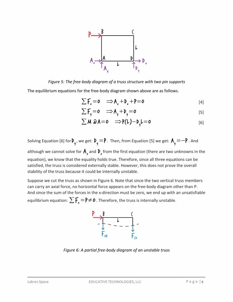
To answer the question, let’s examine the equilibrium equations associated with the structure when it is subjected to a horizontal load. Suppose we apply a non-zero force P at joint B, as shown in Figure 5.
EDUCATIVE TECHNOLOGIES, LLC Lab101.Space P a g e | 4
Figure 5: The free-body diagram of a truss structure with two pin supports
The equilibrium equations for the free-body diagram shown above are as follows.
= ⇒ + + =∑ x x xF 0 A D P 0 [4]
= ⇒ + =∑ y y yF 0 A D 0 [5]
= ⇒ − =∑ yM @A 0 P(L) D L 0 [6]
Solving Equation [6] for yD , we get: =yD P . Then, from Equation [5] we get: =−yA P . And
although we cannot solve for xA and xD from the first equation (there are two unknowns in the
equation), we know that the equality holds true. Therefore, since all three equations can be satisfied, the truss is considered externally stable. However, this does not prove the overall stability of the truss because it could be internally unstable.
Suppose we cut the truss as shown in Figure 6. Note that since the two vertical truss members can carry an axial force, no horizontal force appears on the free-body diagram other than P. And since the sum of the forces in the x-direction must be zero, we end up with an unsatisfiable
equilibrium equation: = ≠∑ xF P 0 . Therefore, the truss is internally unstable.
Figure 6: A partial free-body diagram of an unstable truss

EDUCATIVE TECHNOLOGIES, LLC Lab101.Space P a g e | 5
Now, let’s determine the stability condition of the truss shown in Figure 7.
Figure 7: A rectangular truss with nine members
Similar to the previous example, this truss is externally stable as there are enough support reactions to prevent the rigid-body motion of the entire structure. But is it also stable internally?
The presence of three parallel members (AD, CF, and BE), which results in three parallel forces in the free-body diagram of the truss, may be an indication of the internal instability of the structure. Suppose we place a horizontal force at joint D, as shown below. Now if we cut the truss along the three vertical members, the following free-body diagram results.
Figure 8: A partial free-body diagram of a rectangular truss
Since the free-body diagram yields an unsatisfiable equilibrium equation, = ≠∑ xF P 0 , the
truss is considered unstable. We can classify this as internal instability since it is related to the member forces as opposed to the support reactions.
We may also be able to decide if a truss is unstable by comparing the number of its equilibrium equations with the number of its unknowns. According to the Method of Joints, the number of equilibrium equations in a truss equals two times its number of joints, and the number of unknowns equals the number of support reactions plus the number of member forces. A truss is considered unstable if the number of equations is greater than the number of unknowns.
EDUCATIVE TECHNOLOGIES, LLC Lab101.Space P a g e | 6
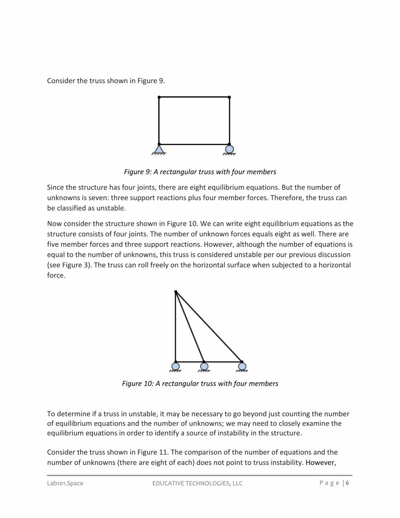
Consider the truss shown in Figure 9.
Figure 9: A rectangular truss with four members
Since the structure has four joints, there are eight equilibrium equations. But the number of unknowns is seven: three support reactions plus four member forces. Therefore, the truss can be classified as unstable.
Now consider the structure shown in Figure 10. We can write eight equilibrium equations as the structure consists of four joints. The number of unknown forces equals eight as well. There are five member forces and three support reactions. However, although the number of equations is equal to the number of unknowns, this truss is considered unstable per our previous discussion (see Figure 3). The truss can roll freely on the horizontal surface when subjected to a horizontal force.
Figure 10: A rectangular truss with four members
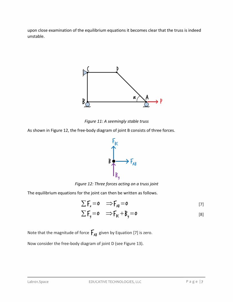
To determine if a truss in unstable, it may be necessary to go beyond just counting the number of equilibrium equations and the number of unknowns; we may need to closely examine the equilibrium equations in order to identify a source of instability in the structure. Consider the truss shown in Figure 11. The comparison of the number of equations and the number of unknowns (there are eight of each) does not point to truss instability. However,
EDUCATIVE TECHNOLOGIES, LLC Lab101.Space P a g e | 7
upon close examination of the equilibrium equations it becomes clear that the truss is indeed unstable.
Figure 11: A seemingly stable truss
As shown in Figure 12, the free-body diagram of joint B consists of three forces.
Figure 12: Three forces acting on a truss joint
The equilibrium equations for the joint can then be written as follows.
= ⇒ =∑ x ABF 0 F 0 [7]
= ⇒ + =∑ y BC yF 0 F B 0 [8]
Note that the magnitude of force ABF given by Equation [7] is zero.
Now consider the free-body diagram of joint D (see Figure 13).

EDUCATIVE TECHNOLOGIES, LLC Lab101.Space P a g e | 8
Figure 13: Two forces acting on a truss joint
The equilibrium equations for the joint are given bellow.
= ⇒ − =∑ x AD CDF 0 F cos(α) F 0 [9]
= ⇒− = ⇒ =∑ y AD ADF 0 F sin(α) 0 F 0 [10]
From Equation [10] we can deduce that =ADF 0 .
Finally, let’s examine the free-body diagram for joint A (see Figure 14).
Figure 14: Four forces acting on a truss joint
The equilibrium equations for the joint are written below.
= ⇒ − = ⇒ =∑ x AB ABF 0 P F 0 F P [11]
= ⇒ =∑ y yF 0 A 0 [12]
Note the contradictory values for ABF given by Equations [7] and [11]. Since the magnitude of
the force cannot be zero and P at the same time, the equilibrium equations are considered unsatisfiable. Hence, the truss is unstable.
Figure 15 shows another unstable truss.

EDUCATIVE TECHNOLOGIES, LLC Lab101.Space P a g e | 9
Figure 15: An internally unstable truss
The structure consists of seven joints, four support reactions, and ten member forces. Therefore, the number of equations (fourteen) is equal to the number of unknowns. Since this equality does not suggest instability, we need to analyze the equilibrium equations in order to prove the instability of the truss.
Suppose the structure is subjected to a vertical load of P as shown in Figure 16.
Figure 16: An internally unstable truss subjected to a concentrated load
The free-body diagram for the entire truss can be drawn as shown below. Note that neither yA
nor yB can be zero, since they must add up to P .
Figure 17: Free-body diagram for an internally unstable truss subjected to a concentrated load
Now, suppose we cut the truss into two parts at joint C, as shown in Figure 18. If the structure is stable, the equilibrium equations must hold true for each part.

EDUCATIVE TECHNOLOGIES, LLC Lab101.Space P a g e | 10
Figure 18: Free-body diagrams for two parts of an unstable truss
The moment equilibrium equation for the left part of the truss can be written as:
= ⇒ − = ⇒ =∑ y yM @A 0 2LC PL 0 C P [13]
Similarly, for the right part of the truss we can write:
= ⇒ = ⇒ =∑ y yM @C 0 2LC 0 C 0 [14]
However, Equations [13] and [14] result in contradictory values for yC . The first equation
indicates that yC has a magnitude equal to P , but the second equation gives zero for the
magnitude of the force. The two equations are not satisfiable. Therefore, the truss is classified as unstable.
In some cases, we may be able to determine the stability of a truss systematically using a deductive approach. Consider the truss shown in Figure 19.
Figure 19: A stable truss configuration
We can prove the stability of the truss using deductive reasoning. We start with an initial stable shape that is a part of the truss. Here, we use the assembly shown in Figure 20. This simple configuration consists of two pin supports and two inclined truss members forming a stable mechanism. Any loads applied to the three joints of the mechanism can be safely transferred to

EDUCATIVE TECHNOLOGIES, LLC Lab101.Space P a g e | 11
the pin supports without causing any rigid-body movement. To put it differently, none of the equilibrium equations for the joints or for the entire mechanism are going to be violated under any loading scenario.
Figure 20: A stable truss configuration
Given the stable configuration above, we can construct another stable configuration by adding two truss members (connected at an angle) as shown in the figure below.
Figure 21: A simple addition rule for defining stable truss configurations
The repeated application of the above rule allows for the construction of stable trusses from a primitive stable configuration. The following figure illustrates the repeated use of the rule for constructing the truss shown in Figure 19. Therefore, the resulting truss is considered stable.
Figure 22: The repeated application of the addition rule for constructing a stable truss
The process depicted in Figure 22 can be used in reverse to determine if a truss can be reduced to a stable mechanism. Such a reduction is possible only if the source structure is stable. Let us illustrate the reverse process using the truss shown below.

EDUCATIVE TECHNOLOGIES, LLC Lab101.Space P a g e | 12
Figure 23: The subtraction rule for reducing a stable truss to a stable mechanism
In Figure 23, we can reduce truss A to truss B by subtracting the two non-collinear members from A. It can then be said that if truss A is stable, truss B must also be stable. The repeated application of this subtraction step enables us to reduce truss A to a stable mechanism, but only if A is stable. See the figure below for the reduction steps for proving the stability of the source truss (A).
Figure 24: The application of the subtraction rule for deconstructing a truss to a stable
mechanism
A stable truss is either statically determinate or indeterminate. If the number of joint equilibrium equations is equal to the number of unknown forces, the truss is said to be statically determinate. If, however, the number of unknowns is greater than the number of equations, the truss is statically indeterminate. Consider the three stable trusses shown in Figure 25.
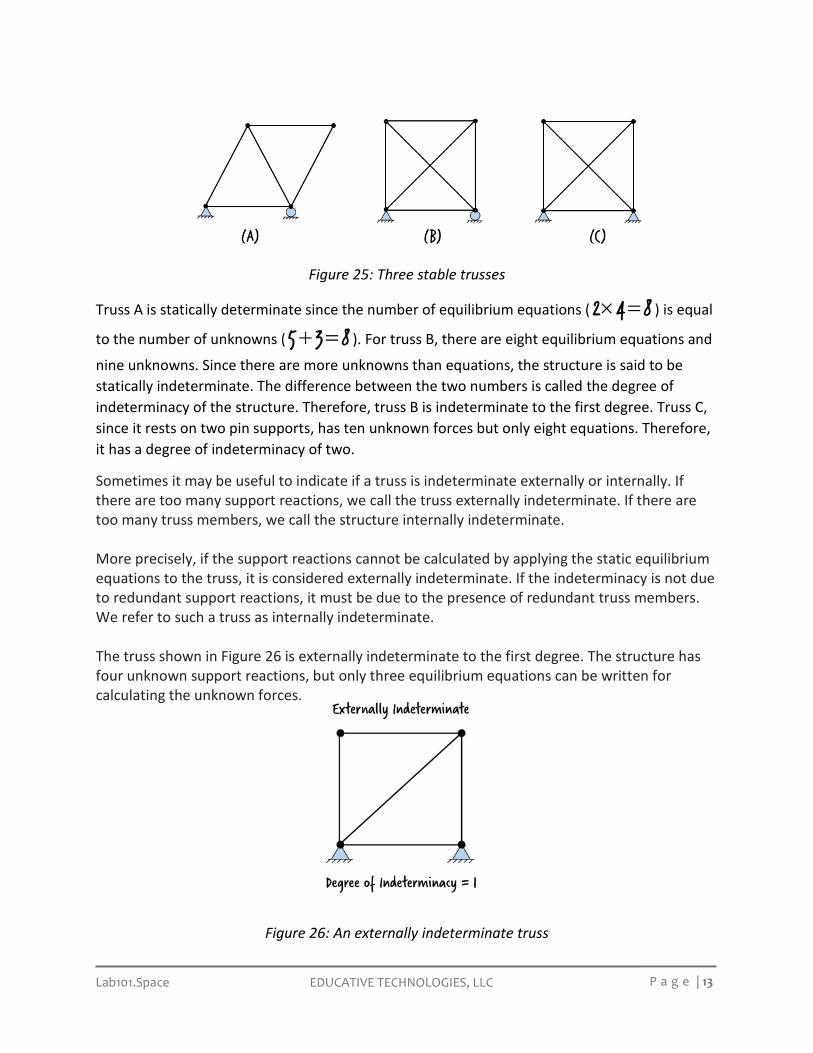
EDUCATIVE TECHNOLOGIES, LLC Lab101.Space P a g e | 13
Figure 25: Three stable trusses
Truss A is statically determinate since the number of equilibrium equations ( × =2 4 8 ) is equal
to the number of unknowns ( + =5 3 8 ). For truss B, there are eight equilibrium equations and
nine unknowns. Since there are more unknowns than equations, the structure is said to be statically indeterminate. The difference between the two numbers is called the degree of indeterminacy of the structure. Therefore, truss B is indeterminate to the first degree. Truss C, since it rests on two pin supports, has ten unknown forces but only eight equations. Therefore, it has a degree of indeterminacy of two.
Sometimes it may be useful to indicate if a truss is indeterminate externally or internally. If there are too many support reactions, we call the truss externally indeterminate. If there are too many truss members, we call the structure internally indeterminate. More precisely, if the support reactions cannot be calculated by applying the static equilibrium equations to the truss, it is considered externally indeterminate. If the indeterminacy is not due to redundant support reactions, it must be due to the presence of redundant truss members. We refer to such a truss as internally indeterminate. The truss shown in Figure 26 is externally indeterminate to the first degree. The structure has four unknown support reactions, but only three equilibrium equations can be written for calculating the unknown forces.
Figure 26: An externally indeterminate truss

EDUCATIVE TECHNOLOGIES, LLC Lab101.Space P a g e | 14
The truss shown in Figure 27(a) is externally determinate, but internally indeterminate to the second degree. Therefore, the overall degree of indeterminacy of the system is two.
Figure 27: Two indeterminate trusses
The truss shown in Figure 27(b) is externally and internally indeterminate. The overall degree of indeterminacy of the structure is three.
Now consider the truss shown in Figure 28. There are fifteen unknown forces and sixteen equilibrium equations associated with the structure. Therefore, the structure is indeterminate to the first degree. However, even though there are four support reactions, the indeterminacy is not external; it is internal.
Figure 28: An internally indeterminate truss

EDUCATIVE TECHNOLOGIES, LLC Lab101.Space P a g e | 15
In this case, we can calculate the support reactions using the static equilibrium equations. Note the two substructures obtained by splitting the truss at joint C (see Figure 29). We can write three static equilibrium equations for each substructure. Since the free-body diagram shows six unknown forces, we can calculate them using the six equilibrium equations. Therefore, the indeterminacy associated with the truss is not external; the truss must be internally indeterminate. Here, the indeterminacy stems from the presence of a redundant truss member in the right segment of the structure.
Figure 29: Two substructures of an internally indeterminate truss
The techniques described in this lecture provide a useful means of determining the stability and determinacy of typical truss structures. The following exercise problems are designed to reinforce the basic concepts discussed above.

EDUCATIVE TECHNOLOGIES, LLC Lab101.Space P a g e | 16
Exercise Problems: Determine the stability and determinacy of the following trusses.