structural optimisation with fracture strength constraints
TRANSCRIPT
Structural optimisation with fracture strength constraints
R. Jones a,*, P. Chaperon a, M. Heller b
a Department of Mechanical Engineering, Monash University, Wellington Road, Clayton, Vic. 3168, Australiab Airframes and Engines Division, Aeronautical Research Laboratory, Defence Science and Technology Organisation,
506 Lorimer St, Pt Melbourne, Vic. 3207, Australia
Received 22 September 2000; received in revised form 8 January 2002; accepted 16 January 2002
Abstract
When considering the problem of shape optimisation with residual strength constraints it was recently found [1] that
there were cases when the optimal shape for a body without an initial flaw was not the same as the optimal solution for
a body with an initial flaw. It was also found that for the optimal case the stress intensity factors, for same length cracks
emanating at right angles to any arbitrary point around the hole, were approximately constant along most of its cir-
cumference. As a result of this finding the present paper presents a new biological algorithm for the optimal design of
structural components with fracture, i.e. residual strength, constraints. This approach is illustrated by considering the
problem of an optimum cut-out geometry for a rectangular plate subjected to a bi-axial stress field and the problem of
the shape optimisation of a fillet with residual strength constraints. � 2002 Published by Elsevier Science Ltd.
Keywords: Optimisation; Finite element analysis; Fracture strength
1. Introduction
Fatigue life extension strategies, such as shape reworking, are being increasingly used to restore theairworthiness and availability of ageing structural components. Structural hot spots are commonly re-worked to remove service induced cracking. Furthermore, to ensure that the damage tolerance of thestructure is not compromised the rework is frequently designed so as to minimise local peak stresses. Recentdevelopments in the methodology and computer implementation of structural optimisation offer the po-tential for significant improvements in the design or specification of such rework profiles. For some reworkcases cracks cannot be fully removed and in the structural optimisation work undertaken to date the effectof such a flaw, after reworking, has not been accounted for. Hence the interplay of an initial optimal reworkshape (determined for the case when no crack was present) and an existing (initial) crack is an importantissue that needs to be addressed and which to date has received little attention [1–6].
Engineering Fracture Mechanics 69 (2002) 1403–1423
www.elsevier.com/locate/engfracmech
*Corresponding author. Tel.: +61-03-990-53809; fax: +61-03-9905-1825.
E-mail address: [email protected] (R. Jones).
0013-7944/02/$ - see front matter � 2002 Published by Elsevier Science Ltd.
PII: S0013-7944 (02 )00006-1

Unfortunately, current optimum design tools do not readily lend themselves to treating fracture strengthas a design constraint. This is because the majority of the life of a component is frequently used up as cracksgrow from an initial non-detectable (semi-elliptical) flaw to a complex flaw size, which is detectable. Thus ateach stage of the life of the component it is necessary to analyse a complex two-dimensional (2-D) or three-dimensional (3-D) flaw under arbitrary loading. Due to the singularity along the crack (flaw) front thisrequires a fine numerical mesh. This in turn means a large number of degrees of freedom and the resultantstructural optimisation problem becomes extremely time consuming, requires large computer resources andis computationally inefficient.
As a result of these shortcomings the boundary element method (BEM) has recently been used in shapeoptimisation [4,7]. The alternating finite element technique [1,13–16], which makes extensive use of theanalytical solutions for 2-D and 3-D flaws subject to arbitrary crack face loading, is another possibleapproach. To date this technique has been successfully applied to solve a large range of 2-D and 3-Dproblems, see [13–16] and formed the basis of the methodology used in [1].
In a damage tolerant design/analysis initial flaws are considered to be present at each of the ‘‘hot spots’’in the structure and these initial flaws are allowed to grow. At each stage in the life of the structure thecurrent crack length(s) are evaluated and the associated stress intensity factors K are computed. Thesevalues of K are then used to evaluate both the residual strength and the crack growth rate associated witheach crack. At no stage in operational life of the structure should the residual strength fall beneath limitload. In the aerospace industry the initial flaws tend to be quite small. In contrast, in the mining and railindustries these (initial) flaws can be quite large. Indeed, it is common for the initial flaws associated withrail bogeys to be between 5–15 mm deep and 10–40 mm long. In the rail industry one immediate challenge isto significantly increase the tonnage carried and to lighten the bogies. The findings of the present reportindicates that to achieve this goal it may be best to use a fracture rather than a stress based optimisationprocess.
Although this paper focuses on the problem of designing to ensure a specific residual strength it shouldbe noted that, as commented on by Visick [11], mechanical repairs cannot usually be expected to restore theoriginal fatigue life of the parent structure. As a result it is generally accepted that, to ensure continuedairworthiness, a scheduled inspection process is essential. Consequently, for an optimal repair design, or astructural modification, the problem of choosing geometry to optimise the inspection intervals also needs tobe considered.
This paper extends the genetic, also termed biological, algorithms [6,8–10] to the optimal design ofstructures with residual strength constraints. One significant finding is that there are cases when structuresoptimised for static (fracture) strength can in fact be lighter than those optimised for stress. We also showthat the optimisation process can lead to a local minimum. From this it follows that shapes, and reworkgeometries, that have been obtained using stress based optimisation techniques should be evaluated toassess their effect on the fatigue life and the residual strength of the structure.
This methodology may have to be modified when considering the problem of wide spread fatiguedamage, or multi-site damage. A detailed review of occurrence and the effects wide spread fatigue damage isgiven in [12].
2. Optimisation with residual strength constraints
Consider the problem of optimising the structural shape of a hole (cut out) with the goal of maximisingthe residual strength. When designing an optimum shape, to achieve a required static strength, a knowledgeof the initial crack size is important. In general the initial crack size would be determined by the nature ofthe non-destructive inspection equipment used to detect flaws during the life of the component and as suchwould be industry dependent.
1404 R. Jones et al. / Engineering Fracture Mechanics 69 (2002) 1403–1423

In this study we do not assume a knowledge of the location of the cracking and the optimisation processconsiders cracking at all points along edge of the hole. However, for simplicity it will be assumed that theinitial flaw is planar.
In this paper the stress intensity factors are computed using the finite element alternating technique, for asingle crack, see Refs. [13–16] for more details. The advantage of this formulation is that, for any givengeometry, once the uncracked problem has been solved then the computation of the stress intensity factorsfor any given crack only involves a small amount of additional work.
When considering the problem of shape optimisation with fracture constraints it was recently found [1]that, for the optimal solution, for a given crack length the stress intensity factors were essentially constantalong of its circumference. This behaviour is intuitively expected for an optimised geometry where it wouldbe hoped that all locations around the hole would be equally critical. A similar behaviour was found whenconsidering shape optimisation with durability, i.e. crack growth, constraints. In this case it was hypoth-esised that the optimum shape would be such that all locations around the cut-out would be equally fatiguecritical.
This finding suggests that the basic biological optimisation algorithm for the optimal design of structuralcomponents with stress constraints (see [6,8–10]) can be extended to include fracture constraints. Theimplementation of this algorithm attempts to obtain a constant stress state at all points (nodes) along theboundary. To this end boundary nodes are moved a distance di where
di ¼ ðri � rthÞrs=rth
Here ri is the hoop stress at the ith node, as calculated by the finite element program, r is a characteristiclength, s is a step size, usually in the range 0.1–0.3, and rth is a threshold value of the stress. The thresholdvalue rth is often set as the average, maximum, value of the stress around the circumference. (As such thevalue of a rth changes at each iteration.) In this approach convergence is monitored via the objectivefunction Y
Y 2 ¼X
ðri � rthÞ2=ðP � 1Þ
which is summed over the total number of nodes (P) along the boundary.This concept can be extended to allow for static fracture considerations. In this new algorithm the ith
point along the boundary would be moved a distance di where
di ¼ ðKi � KthÞrs=Kth
Here r and s would be as before, Ki is the value of the (effective) stress intensity factor at the ith point, andKth is the maximum value of the stress intensity factor around the circumference. In this approach con-vergence is best judged by monitoring the maximum value of the stress intensity factor Kmax
eff , whereKeff ¼
pðK2I þ K2
IIÞ, for the problem of interest. In this approach convergence is a user defined quantitywhich in this study we set to �1%, i.e. when j1� DKmax
eff =Kmaxeff j6 0:99.
If the crack size is very small in comparison to the length scale associated with the cut-out, or localrework, then the stress intensity factors will be directly related to the tangential stress around the cut-out. Inthis case moving nodes based on the local stress field or based on the local stress intensity factor wouldproduce an identical geometry. However, the two approaches diverge as the (relative) crack size increases.
For non-aerospace components the initial defect size can be quite large. For example, hot tears found inrail bogeys are often observed to be between 20 and 60 mm long and between 5 and 15 mm deep. In generalthe critical crack size can be quite large so that optimising for static (fracture) strength can produce a shapethat differs from the optimal shape obtained on the basis of static strength considerations.
In the present optimisation study a large number of individual cracks, normal to the local surface, of agiven (initial) size are included along the boundary to be optimised. One advantage of the finite element
R. Jones et al. / Engineering Fracture Mechanics 69 (2002) 1403–1423 1405

alternating technique is that these cracks can be modelled separately with the same (uncracked) simple finiteelement mesh.
2.1. Static strength optimisation example: hole in a 2 1 bi-axial stress field
The first problem to be considered consists of a aluminium alloy square plate, which 1 mm thick plateand has a (side) length of 600 mm, with a centrally located hole subjected to a remote bi-axial stress field of100 MPa 50 MPa (see Fig. 1). The initial hole geometry is a 20 mm wide by 40 mm long elliptical hole in a(see Fig. 1) which represents the geometry obtained using a stress based optimisation process. The holeshape is constrained to be no wider than 20 mm (see Fig. 1). Note that the hole is symmetrical aboutits vertical and horizontal mid-planes, so only the first quadrant of the hole geometry needs to be defined.Fig. 2 also presents a schematic defining the parametric co-ordinate system used to define points along theboundary of the hole. The upper most point on the hole is the zero position, while the point on the hor-izontal mid-plane is the last node.
Several crack sizes were considered for static strength optimisation; namely 1.0, 2.5, 5.0 and 10.0 mm.For brevity, the details for the optimisation will not be described here. Fig. 3 shows the resulting optimisedgeometries. The original shape is defined as the zero crack length solution, as this is the stress optimisedsolution. Figs. 4–7 show the convergence rates as well as the difference in effective stress intensity factor,defined as Keff ¼
pðK2I þ K2
IIÞ, between the initial (stress optimal) shape, i.e. the 2:1 ellipse, and the optimal(static strength) shape for the crack sizes 1.0, 2.5, 5.0 and 10.0 mm respectively. Note that with this defi-nition Keff is always positive.
This problem had previously been solved for the case of a 2.5 mm flaw using a simple optimisationtechnique, for details see [1]. It should be noted that the present (near) optimal shape and that obtained in[1] are in excellent agreement.
These results show that the geometry can be optimised to reduce the maximum effective stress intensityfactor. The reduction of maximum value Keff ranged from �5% to 8% for the 1.0 mm crack case to �13%for the 10.0 mm crack case. However, it can be seen from the Keff plots that the curve is not smooth near theupper end of the hole (i.e. parametric position near zero). This is most likely due to the fact that the designspace is relatively flat. The local perturbations in shape increase as the final shape deviates further from the
Fig. 1. Schematic of problem under consideration.
1406 R. Jones et al. / Engineering Fracture Mechanics 69 (2002) 1403–1423

initial shape and the numerical errors accumulate. To overcome this the optimised shapes could have beensmoothed and the process than restarted. This was not done so as to illustrate the ‘‘warts and all’’ nature ofthe problem.
One interesting feature of this example is that the current optimised shape contains less material than thestress optimised body. This means that structures optimised for static (fracture) strength can be lighter thanthose optimised for stress.
Fig. 3. Optimised hole shapes for static strength with crack sizes 0, 1.0, 2.5, 5.0, and 10.0 mm.
Fig. 2. Schematic of the boundary and the parametric position definition.
R. Jones et al. / Engineering Fracture Mechanics 69 (2002) 1403–1423 1407

Despite the flat design space, by this we mean that relatively large changes in geometry can result in smallchanges in Keff , the (near) optimal shapes form a continuous family of curves (see Fig. 3).
2.2. Example 2: fillet profile optimisation of a stepped uni-axially loaded plate
In most practical problems that arise in the aerospace industry it is generally not possible to continu-ously enlarge a cut-out or remove material. In most cases a limit on the size of the cut-out or reworkgeometry is imposed. Consequently examples 2–5 were to chosen to have constraints on the maximumpermissible profile.
Fig. 4. (a) Comparison of Keff for initial and optimised hole for crack size 1.0 mm. (b) Convergence for 1.0 mm crack.
1408 R. Jones et al. / Engineering Fracture Mechanics 69 (2002) 1403–1423

The second example considers a long 1 mm thick aluminium alloy plate subjected to a remote uni-axialstress of 100 MPa (see Fig. 8). Initially the width of the plate increases from 200 to 250 mm via a 25 mmradius fillet. The profile to be optimised includes the fillet boundary as well as an additional 25 mm of thethinner section. The profile is constrained such that the fillet shape cannot move to the left of a line 200 mmfrom the fixed end of the structure (see Fig. 8). Although the panel is symmetric, cracks are only consideredon one side. The optimum fillet shapes were calculated for cracks normal to the surface of lengths 1.0, 2.5,5.0 and 10.0 mm. The effective stress intensity factors were compared with the initial geometry for each case(see Figs. 9–14). In general, the reductions achieved were between 15% and 35%, the improvement reducedas the crack size increased, i.e. the design space was relatively flat for large crack lengths. Indeed, despite theflat design space the (near) optimal shapes formed a continuous family of curves (see Fig. 10). For any onecrack size the relatively flat design space is again reflected by local perturbations in the shape of the (near)optimal geometry (see Fig. 10) and that the (local) perturbations increase as the geometry diverges from theinitial shape, i.e. the numerical errors accumulate.
2.3. Example 3: a 20 mm constrained hole in a uni-axially loaded plate
Let us next consider the problem of a 1 mm thick, 600 mm square aluminium plate, containing acentrally located 20 mm wide hole, subjected to a remote uni-axial stress of 100 MPa (see Fig. 15). The
Fig. 5. (a) Comparison of Keff for initial and optimised hole for crack size 2.5 mm. (b) Convergence for 2.5 mm crack.
R. Jones et al. / Engineering Fracture Mechanics 69 (2002) 1403–1423 1409

optimisation problem is specified to find the optimum shape of the hole, where the height of the hole isconstrained to be less than 20 mm. The starting (initial) shape is again the stress optimised shape, i.e. with acrack length a of 0.0 (see Fig. 16).
This example was chosen because of the inherent difficulty in optimising hole shapes under uni-axialloading. It also possesses the following features:
(1) As the crack size increases the maximum value of the stress intensity factor Keff , defined as Kmaxeff ,
should become relatively insensitive to the shape of the hole. Thus for large cracks the final shapeand the initial shape should have very similar values of Kmax
eff .(2) As the crack sizes increase the individual (near) optimal geometries should form a continuous family
of curves. Thus although the design space should be flat the (near) optimal geometries should form acontinuous family.
The (near) optimum shapes found by this optimisation process, for the 1.0, 2.5, 5.0 and 10 mm crackcases, are shown in Fig. 16. For comparison the values of Keff for a circular hole are also presented, recallthat with the definition of Keff means that it will always be positive. In each case the starting solution wasthe stress optimised shape, i.e. a crack length a ¼ 0:0 mm. For the 1.0, 2.5, and 5.0 mm length cracks thesegeometries yielded Kmax
eff values significantly less than those obtained for the initial stress optimised cases(see Figs. 17–19). However, as required, for the 10 mm long crack the value of Kmax
eff was essentially the
Fig. 6. (a) Comparison of Keff for initial and optimised hole for crack size 5.0 mm. (b) Convergence for 5.0 mm crack.
1410 R. Jones et al. / Engineering Fracture Mechanics 69 (2002) 1403–1423

Fig. 8. Geometry and loading of the filleted plate (only half model shown).
Fig. 9. Schematic representation of the fillet geometry and parametric position used in the optimisation process.
Fig. 7. (a) Comparison of Keff for initial and optimised hole for crack size 10.0 mm. (b) Convergence for 10.0 mm crack.
R. Jones et al. / Engineering Fracture Mechanics 69 (2002) 1403–1423 1411

same, i.e. to within the accuracy of the numerical method, for a circular hole, Kmaxeff ¼ 21:2 MPa
pm the
stress based optimal shape, Kmaxeff ¼ 21:9 MPa
pm, and for the shape obtained by the present biological
algorithm, Kmaxeff ¼ 22:3 MPa
pm (Figs. 20 and 21).
This example again confirms that, despite the design space being flat, the (near) optimal geometries forma continuous family of curves.
Fig. 10. Optimised fillet shapes for with crack sizes 0, 1.0, 2.5, 5.0, and 10.0 mm.
Fig. 11. Comparison of Keff for initial and optimised fillet for crack size 1.0 mm.
Fig. 12. Comparison of Keff for initial and optimised fillet for crack size 2.5 mm.
1412 R. Jones et al. / Engineering Fracture Mechanics 69 (2002) 1403–1423

Fig. 13. Comparison of Keff for initial and optimised fillet for crack size 5.0 mm.
Fig. 14. Comparison of Keff for initial and optimised fillet for crack size 10.0 mm.
Fig. 15. Schematic of the 20 mm constrained hole problem.
R. Jones et al. / Engineering Fracture Mechanics 69 (2002) 1403–1423 1413

2.4. Example 4: a 40 mm constrained hole in a uni-axially loaded plate
To further illustrate these findings, i.e. the flat design space, that the (near) optimal geometries form acontinuous family of curves and that the stress and that K optimised shapes can differ, were not confined tothis specific cases presented above the problem was reanalysed with the maximum permissible height in-creased to 40 mm. The results are shown in Figs. 22–26.
Fig. 16. Comparison of 20 mm constrained hole shapes for initial, stress optimised and K optimised for crack sizes of 1.0, 2.5, and 10.0
mm.
Fig. 17. Comparison of Keff for initial and optimised 20 mm constrained hole for a crack size of 1.0 mm.
Fig. 18. Comparison of Keff for initial and optimised 20 mm constrained hole for crack size 2.5 mm.
1414 R. Jones et al. / Engineering Fracture Mechanics 69 (2002) 1403–1423

Both studies again revealed that the biological growth algorithm converged and, for the smaller cracksizes considered, gave geometries that were significantly less critical than the initial circular hole. The levelof improvement, for the 1.0, and 2.5 mm crack lengths, with respect to the stress optimised geometry was afunction of the length scales involved. By this we mean that the improvements were greater for the casewhen the height was confined to be less than 20 mm. Furthermore, as required, both cases revealed that forlarge cracks the values of Kmax
eff was relatively insensitive to the shape of the hole.We again see that, as required, despite the design space being flat the (near) optimal geometries form a
continuous family of curves.These examples again reveal that the optimised shape contains less material than the stress optimised
body. This means that structures optimised for static (fracture) strength can in fact be lighter than thoseoptimised for stress.
2.5. Example 5: a constrained hole near an edge in a uni-axially loaded plate
It is commonly thought that stress optimised shapes should lead to stress intensity factors that are lowerthan those associated with the initial geometry. The present example will show that this is not always true
Fig. 19. Comparison of Keff for initial and optimised 20 mm constrained hole for crack size 5.0 mm.
Fig. 20. Comparison of Keff for initial and optimised 20 mm constrained hole for crack size 10.0 mm.
R. Jones et al. / Engineering Fracture Mechanics 69 (2002) 1403–1423 1415

and that we can obtain a local minimum rather than a global minimum. To illustrate this we will considerthe problem of a hole near a free edge (see Fig. 27) in a rectangular panel under a remote uniform stress of
Fig. 21. Schematic of the 40 mm constrained hole problem.
Fig. 22. Comparison of 40 mm constrained hole shapes for initial, stress optimised and K optimised for crack sizes of 1.0, 2.5, 5.0, and
10.0 mm.
1416 R. Jones et al. / Engineering Fracture Mechanics 69 (2002) 1403–1423
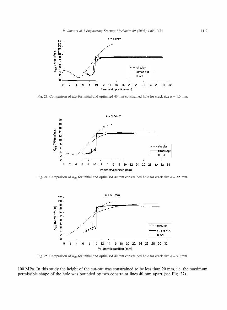
100 MPa. In this study the height of the cut-out was constrained to be less than 20 mm, i.e. the maximumpermissible shape of the hole was bounded by two constraint lines 40 mm apart (see Fig. 27).
Fig. 23. Comparison of Keff for initial and optimised 40 mm constrained hole for crack size a ¼ 1:0 mm.
Fig. 24. Comparison of Keff for initial and optimised 40 mm constrained hole for crack size a ¼ 2:5 mm.
Fig. 25. Comparison of Keff for initial and optimised 40 mm constrained hole for crack size a ¼ 5:0 mm.
R. Jones et al. / Engineering Fracture Mechanics 69 (2002) 1403–1423 1417

Fig. 26. Comparison of Keff for initial and optimised 40 mm constrained hole for crack size a ¼ 10:0 mm.
Fig. 27. Schematic diagram showing the geometry of the edge hole problem, distances in mm.
The resultant stress optimised shape is shown in Fig. 28. The associated stress fields around the hole areshown in Fig. 29. Let us now consider optimisation with respect to fracture strength when the crack lengthspresent at the hole can be 1.0, 2.5 or 5.0 mm (see Figs. 30–35). In each case the stress optimised shape wasused as a starting geometry to obtain the K optimised solution. In this work a non-dimensional lengthparameter L was used to represent the (non-dimensional) distance along the perimeter of the hole. HereL ¼ 0 and L ¼ 1 are the two symmetry points on the perimeter of the hole.
This worked fine for the 1.0 and the 2.5 mm crack lengths and the fracture strength optimised shapeswere similar to the stress optimised shapes (see Fig. 30). The primary difference in the geometries was that,
1418 R. Jones et al. / Engineering Fracture Mechanics 69 (2002) 1403–1423

Fig. 28. Circular hole, the stress optimised shape, and a simple rectangular cut-out.
Fig. 29. Stress distribution around the circular hole, the stress optimised hole and a simple rectangular cut-out.
Fig. 30. Comparison of the stress optimised, and the fracture strength optimised shapes for a ¼ 0:0, 1.0, 2.5, and 5.0 mm.
R. Jones et al. / Engineering Fracture Mechanics 69 (2002) 1403–1423 1419

Fig. 33. Stress intensity factor distribution around the circular hole and the K optimised hole, starting from the stress optimised shape.
Fig. 31. Stress intensity factor distribution around the circular hole and the optimised shape, starting from the stress optimised shape,
for an initial crack length of 1.0 mm.
Fig. 32. Stress intensity factor distribution around the circular hole and the optimised shape, starting from the stress optimised shape,
for an initial crack length of 2.5 mm.
1420 R. Jones et al. / Engineering Fracture Mechanics 69 (2002) 1403–1423

for the fracture strength optimised shapes, the corners protruded a little so as to shield the side nearest theedge (see Fig. 30). However, for the 5 mm crack the process yielded a local minimum that was not theglobal minima (see Fig. 33). In this case the solution for the circular hole was lower than that obtained fromeither the present solution or that associated with the stress based solution (see Fig. 33).
This behaviour, for the 5.0 mm crack, can be explained by considering the variation in the ryy stress inthe uncracked structure between the hole and the plate edge along the horizontal centreline (see Fig. 34).Over this (10 mm) ligament, between the circular hole and the plate edge, the stress rapidly reduces from apeak value over 400 MPa (see Fig. 29). However, for the stress optimised geometry we obtained a muchlower peak stress and a more uniform stress distribution along the ligament (see Fig. 34). The resultantvariation of the K with crack length, at this position, is shown in Fig. 35 together with the values obtainedusing the FRANC2D software. The present results and those obtained using FRANC2D results differed byless than 3% for all crack lengths considered. This plot clearly shows that the stress optimised profile re-sulted in lower K’s than the circular hole when the crack length was less than 3 mm. However, when thecrack length was greater than �3.5 mm the circular hole produced lower values of K. Indeed, for holes neara free edge it follows that this phenomenon can often occur. The precise crack length at which K, for thestress optimised shape, exceeds that of the original geometry will depend on both the local geometry and theloading conditions. From this it follows that a stress optimised shape can lead to a reduction in the fatigue
Fig. 34. Variation of stress along centreline from hole to the edge of the specimen.
Fig. 35. Variation of K with crack length, centreline of the hole to the edge of the specimen.
R. Jones et al. / Engineering Fracture Mechanics 69 (2002) 1403–1423 1421

life. In this case the phenomena will also depend on the initial flaw size, the NDI process used and theprobability of detection.
This result illustrates that the optimisation process can yield local minima that are not the globalminima. Consequently shapes, and rework geometries, that have been obtained using stress based opti-misation techniques should be evaluated to assess their effect on the fatigue life and the residual strength ofthe structure.
Despite this finding there are many instances where, although the stress and the fracture (or life) opti-mised shapes differ, the stress optimised shape produces results very similar to those obtained using fracture(or life) optimisation. Indeed, as we have seen, it appears that the design space is generally very flat.
3. Summary
This paper has presented a simple algorithm for shape optimisation with residual strength (fracture)constraints. This formulation has been illustrated by considering a range of optimisation problems in-cluding a central hole under bi-axial loading and a simple fillet.
It is tempting to assume that structures that are optimised with respect to stress will also be optimisedwith respect to fracture strength. This will often be true, particularly if the flaw size being considered issmall. (The circumstances under which this is not true are extremely interesting and will be discussed inmore detail in a subsequent paper.) The present paper has shown that this will not be true if the flaw underconsideration is not small. One example of this (i.e. non-small initial flaws) is the rail industry where initialflaws up to 5 mm deep and 10 mm long are quite common. In the rail industry one immediate challenge is tosignificantly increase the tonnage carried and to lighten the bogies. The findings of the present report in-dicate that to achieve this goal it may be best to use a fracture rather than a stress based optimisationprocess. We have also seen that the optimisation process can lead to a local minimum. Consequentlyshapes, and rework geometries, that have been obtained using stress based optimisation techniques shouldbe evaluated to assess their effect on the fatigue life and the residual strength of the structure.
The examples given in the present study indicate that when optimising the shape of a component so as tomaximise its (fracture) strength the stress optimised shape often represents a good starting point. However,we have also seen that this finding is not universally true. At this stage the existence of multiple minima andthe uniqueness of the solution requires significant additional research.
One interesting feature of this work is that structures optimised for static (fracture) strength can in factbe lighter than those optimised for stress. We have also found that, despite the design space being flat, the(near) optimal geometries formed a continuous family of curves. The extension of this technique to opti-mum design with durability constraints, with crack growth allowed to be non-self-similar, will be presentedin a forthcoming paper.
References
[1] Chaperon P, Jones R, Heller M, Pitt S, Rose F. A methodology for structural optimisation with damage tolerance constraints.
J Eng Fail Anal 2000;7:281–300.
[2] El Abdi R, Touratier M, Convert P. Optimal design for minimum weight in a cracked pressure vessel of a turboshaft. Commun
Numer Methods Eng 1996;12:271–80.
[3] Bethge K, Mattheck C. Fatigue testing of a shape-optimized circular hole in a plate under tensile and bending loads. Int J Fatigue
1990;12(6):489–92.
[4] Cheng GD, Fu B. Optimization of continuum with crack. IUTAM Symposium on Structural Optimization, Melbourne, Australia,
1988.
[5] Dulerri AJ, Rajaiah K. Optimum hole shapes in finite plates under uniaxial load. ASME J Appl Mech 1979;46:691–5.
1422 R. Jones et al. / Engineering Fracture Mechanics 69 (2002) 1403–1423

[6] Kaye R, Heller M. Structural shape optimisation by iterative finite element solution. DSTO Research Report RR-0105, 1997.
[7] Jih J, Hajela P. Computational efficiency aspects in boundary element based structural shape optimization. Eng Optimisat
1991;17:161–73.
[8] Mattheck C, Moldenhauer H. An intelligent CAD-method based on biological growth. Fatigue Fract Eng Mater Struct
1990;13(l):41–51.
[9] Mattheck C. Design and growth rules for biological structures and their application to engineering. Fatigue Fract Eng Mater
Struct 1990;13(5):535–50.
[10] Mattheck C, Burkhardt S. A new method of structural shape optimization based on biological growth. Int J Fatigue
1990;12(3):185–90.
[11] Visick J. Damage tolerance/maintenance of airworthiness––an operators viewpoint. International Conference on aircraft Damage
Assessment and Repair, Melbourne, Australia, August 1991. p. 15–22.
[12] Pitt S, Jones R. Multiple site and wide spread fatigue damage in aging aircraft. Eng Failure Anal 1997;4(4):237–57.
[13] Atluri SN, Tong P. Computational schemes for integrity analyses of fuselage panels in aging airplanes. In: Structural Integrity of
Aging Airplanes. Springer-Verlag; 1991.
[14] Nishioka T, Atluri SN. Analytical solution for embedded elliptical cracks and finite element alternating method for elliptical
surface cracks subject to arbitrary loadings. Eng Fract Mech 1983;17(3):247–68.
[15] Jones R, Atluri SN, Pitt S, Williams JF. Developments in the analysis of interacting cracks. J Eng Failure Assess 1995;2(4):307–20.
[16] Jones R, Hammond S, Williams JF, Heller M. A numerical study of MSD in aluminium alloys. J Comput Struct 1995;55(1):177–
83.
R. Jones et al. / Engineering Fracture Mechanics 69 (2002) 1403–1423 1423