structural no. 2 - civil samuraiz · pdf filedesign of crane runway support girders ........
TRANSCRIPT


I
STRUCTURAL ENGINEERS’ HANDBOOK
No. 2

As in the Original Standard, this Page is Intentionally Left Blank

SP:6(2)-1962
HANDBOOK FOR
STRUCTURAL ENGINEERS
2. STEEL BEAMS AND PLATE GIRDERS
BUREAU OF -INDIAN STANDARDS MANAK BHAVAN, 9 BAHADUR SHAH ZAFAR MARG
NEW DELHI 110002
Price Rs 250. $!Q July 1962

BUREAU OF INDIAN STANDARDS
Edition : First 1962
First Reprint : September 1968
Second Reprint : December 1973
Third Reprint : July1975
Fourth Reprint : July 1979
Fifth Reprint : July 1982
Sixth Reprint : April 1999
UDC 624.2/.9:624.072:669.14
0 Copyright 1973
BUREAU OF INDIAN STANDARDS This publication is protected under the Indian Copyright Act (XIV of 1957) and reproduction in whole or in part by any means except with written permission of the publisher shall be deemed to be an infringement of copyright under the said Act.
Printed in India by Simco Printing Press, Delhi; and Published by the Bureau of Indian Standards, New Delhi ( India ).

CONTENTS
FOREWORD ............
SYMBOLS ............
ABBREVIATIONS .........
1.
2.
3.
4.
5.
6.
7.
8.
9.
10.
11.
12.
13.
14.
15.
16.
17.
18.
SECTION I GENERAL
INTRODUCTION . . . . . . . . .
DESIGN PROCEDURE AND CODE OF PRACTICE . . .
SECTION II DESIGN OF ROLLED REAMS
GENERAL ._ . . . . . . . . . .
SELECTION FOR BENDING MOMENT AND SHEAR .,.
LATERAL SUPPORT REQUIREMENTS . . . . . .
DESIGN OF BEAMS WITHOUT LATERAL SUPPORT
DEFLECTION REQUIREMENTS . . . . . .
SHEAR STRESS IN BEAMS . . . . . .
WEB CRIPPLING AND BUCKLING . . . . . .
END CONNECTIONS AND BEARING PLATE DESIGN
DESIGN EXAMPLE OF FLOOR BEAM FRAMING . . .
SECTION Ill DESIGN OF PLATE GIRDERS
GENERAL . . . . . . . . . . . .
. . .
. . .
. . .
. . .
. . .
. . .
. . .
. . .
. . .
. . .
. . .
. . .
. . .
. . .
. . .
PRELIMINARY SELECTION OF WEB PLATE FOR ECONOMICAL DEPTH . . . . . . . . . . . . . . .
TRIAL FLANGE SELECTION FOR MAXIMUM MOMENT . . .
CHECKING, OF WEIGHT ESTIMATES . . . . . . . . .
DESIGN BY MOMENT OF INERTIA METHOD . . . . . .
DETERMINATION OF FLANGE THICKNESS REDUCTION POINTS
TRANSFER OF SHEAR STRESS FROM WEB TO FLANGE . . .
5
PAGE
9
13
17
19
25
27
27
28
29
30
30
30
31
31
L
49
49
50
51
51
51
52

ISI HANDBOOK FOR STRUCTURAL ENGINEERS: STEEL BEAMS AND PLATE GIRDRRS
19.
20.
21.
22.
23.
24.
25.
26.
27.
28. 29.
30.
31.
32.
33.
34.
35.
36.
37.
38.
39.
40.
4-l .
42‘
DESIGN OF BEARING STIFFENERS . . . . . . DESIGN OF INTERMEDIATE STIFFENERS . . . DESIGN OF SPLICES . . . . . . . . . DESIGN OF END CONNECTIONS . . . . . . DESIGN EXAMPLE OF WELDED PLATE GIRDER . . . RIVETED PLATE GIRDER . . . . . . . . . DESIGN EXAMPLE OF RIVETED PLATE GIRDER . . .
. . . :.. . . . . . . . . . . . . . . .
SECTION IV NUMERICAL ANALYSIS OF BENDING MOMENTS AND DEFLECTIONS JN BEAMS
GENERAI. . . . . . . . . . . . . . . . NEWMARK’S NUMERICAL PROCEDURE . . . . . .
SECTION V SPECIAL PROBLEMS IN BEAM AND GIRDER
GENERAL ...............
BIAXIAL BENDING ............
BIAXIAL BENDING OF A SECTION WITH AN AXIS OF SYMMETRY DESIGN EXAMPLE OF BIAXIAL LOADED BEAM ......
LATERALLY CONSTRAINED BENDING OF SECTIONS WITH No Axrs OF SYMMETRY ............
DESIGN EXAMPLE OF ANGLE SECTION BEAM LOADED IN THF. PLANE OF WEB ............
UNCONSTRAINED BENDING OF,SECTIONS WITH No AXIS OF SYMMETRY ............
DESIGN EXAI&LE OF ANGLE BEAM LOADED PARALLEL TO ONE SIDE ............
DESIGN EXAMPLE OF ANGLE BEAN DESIGN BY DRAWING CIRCLE 0~ INERTIA .............
BENDING OF CHANNELS WITHOUT TWIST ......
DESIGN EXAMPLE OF SINGLE CHANNEL AS BEAM ...
COMBINED BENDING AND TORSION .........
DESIGN EXAMRLE OF BOX GIRDER FOR COMBINED BENDING AM) TORSION ............
DESIGN OF CRANE RUNWAY SUPPORT GIRDERS ......
DESIGN EXAMPLE OF CRANE RUNWAY SUPPORT GIRDER
PAGE
52
53
53
54
54
70
70
85
85
99
99
99
101
104
104
107
107
109 L 112 1~12 115
118 121 121
6
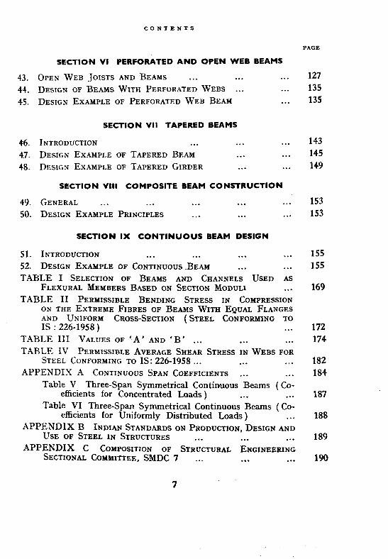
43. OPEN WEB JOISTS AND BEAMS . . . . . . . . . 127
44. DESIGN OF BEAMS WITH PERFORATED WEBS . . . . . . 135
45. DESIGN EXAMPLE OF PERFORATED WEB BEAM . . . 135
SECTION VCI TAPERED BEAMS
46. INTRODIJ~TION . . . . . . . . . 143
47. DE~ICN EXAMPLE OF TAPERED BEAM . . . . . . 145
48. DESIGN EXAMPLE OF TAPERED GIRDER . . . . . , 14.9
SECTION VIII COMPOSITE BEAM CONSTRUCTION
49. 50.
GENERAL . . . . . . . . . . . . . . .
DESIGN EXAMPLE PRINCIPLES . . . . . . . . .
153
153
SECTION IX CONTINUOUS BEAM DESIGN
51.
52. INTRODUCTION . . . . . . . . . . . .
DESIGN EXAMPLE OF CONTINUOUS ABEAM . . . . . .
155
155
169
CONTENTS
SECTION VI PERFORATED AND OPEN WEB BEAMS
TABLE I SELECTION OF BEAMS AND CHANNELS USED AS FLEXVRAL MEMBERS BASED ON SECTION MODULI . . .
TABLE II PERMISSIBLE BENDING STRESS IN COMPRESSION ON THE EXTREME FIBRES OF BEAMS WITH EQUAL FLANGES AND UNIFORM CROSS-SECTION (STEEL CONFORMING TO IS : 226-1958) . . .
TABLE III VALUES OF ‘A’ AND ‘B’ . . . . . . . . .
TABLE IV PERMISSIBLE AVERAGE SHEAR STRESS IN WEBS FOR STEEL CONFORMING TO IS: 226-1958 . . . . . . . . .
APPENDIX A CONTINUOUS SPAN COEFFICIENTS . . . . . .
Table V Three-Span Symmetrical Continuous Beams ( Co- efficients for Concentrated Loads ) . . . . . .
Table VI Three-Span Symmetrical Continuous Beams ( Co- efficients for Uniformly Distributed Loads ) . . .
APPENDIX B INDIAN STANDARDS ON PRODUCTION, DESIGN AND USE OF STEEL IN STRUCTURES . . . . . . . . .
APPENDIX C COMPOSITION OF STRUCTURAL ENGINEERING SECTIONAL COMMI~EE, SMDC 7 _.. . . . . . .
PAGE
172
174
182
184
187
188
189
190
7

As in the Original Standard, this Page is Intentionally Left Blank

FOREWORD
This handbook, which has been processed by the Structural Engineer- ing Sectional Committee, SMDC 7, the composition of which is given in Appendix C, has been approved for publication by the Structural and Metals Division Council of ISI.
Steel, which is a very important basic raw material for industrializa- tion, had been receiving considerable attention from the Planning Commis- sion even from the very early stages of the country’s First Five Year Plan period. The Planning Commission not only envisaged an increase in pro- duction capacity in the country, but also considered the question of even greater importance, namely, the taking of urgent measures for the conser- vation of available resources. Its expert committees came to the con- clusion that a good proportion of the steel consumed by the structural steel industry in India could be saved if ‘higher efficiency procedures were adopted in the production and use of steel. The Planning Commission, therefore, recommended to the Government of India that the Indian Standards Institution should take up a Steel Economy Project and pre- pare a series of Indian Standard Specifications and Codes of Practice in the field of steel production and utilization.
Over six years of continuous study in India and abroad, and the deli- berations eat numerous sittings of committees, panels and study groups, have resulted in the formulation of a number of Indian Standards in the field of steel production, design and use, a list of which is included in Appendix B.
The basic Indian Standards on hot rolled structural steel sections are:
IS: 808-1957 SPECIFICATION FOR ROLLED STEEL BEAM, CHANNEL AND ANGLE SECTIONS
IS: 811-1961 SPECIFICATION FOR COLD FORMED LIGK~ GAUGE STRUC- TURAL STEEL SECTIONS
IS: 1161-1958 SPECIFICATION FOR STEEL TUBES ~08 STRUCTURAL PURPOSES
IS: 1173-1957 SPECIFICATION FOR ROLLED STEEL SECTIONS, TEE BARS
IS: 1252-1958 SPECIFICATION FOR ROLLED STEEL SECPIONS, BULB ANGLES
IS: 1730-1961 DIMENSIONS FOR STEEL PLATE, SHEE’I’ AND STRIP FOR STRUCTURAL AND GENERAL ENGINEERING -PURPOSES ( Under print )
9
ISI HANDBOOR FOR STRUCTURAL ENGINEERS: STEEL BEAMS AND PLATE GIKDERS
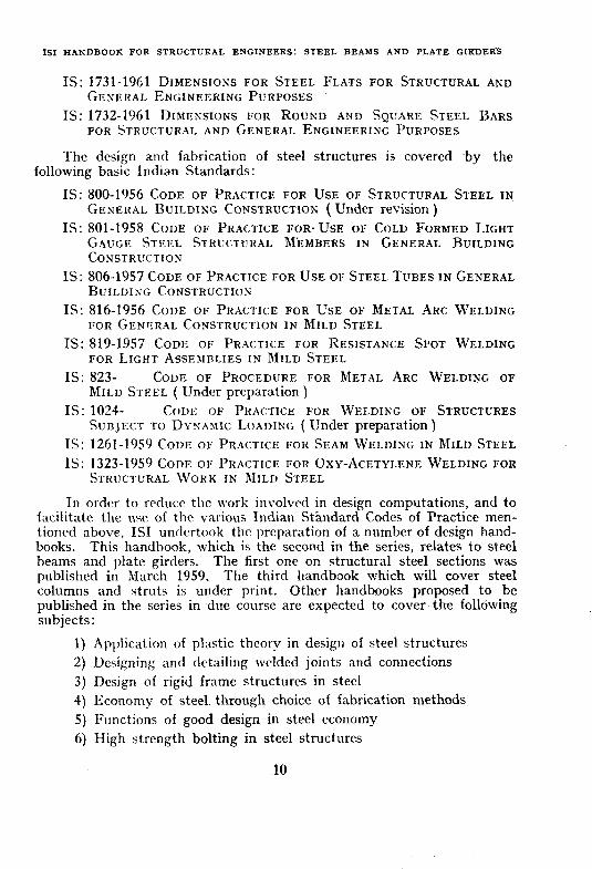
IS: 1731-1961 DIMENSIONS FOR STEEL FLATS FOR STRUCTURAL AND GENERAL ENGINEERING PURPOSES
IS: 1732-1961 DIMENSIONS FOR ROUND AND SQUARE STEEL BARS FOR STRUCTURAL AND GENERAL ENGINEERING PURPOSES
The design and fabrication of steel structures is covered ~by the following basic Indian Standards:
IS: 800-1956 CODE OF PRACTICE FOR USE 01; STRUCTURAL STEEL IN GENERAL BUILDING CONSTRUCTION ( Under revision )
IS: 801-1958 CODE 01; PRACTICE I;OR. USE GAUGE STEEL STRUCTURAL MEMBERS CONSTRUCTION
IS: 806-1957 CODE OF PRACTICE FOR USE OF BUILDIN{; C~NSTRXTION
IS: 816-1956 CODE OF PRACTICE FOR USE
0I; COLD FORMED LIGHT IN GENERAL BUILDING
STEEL TUBES IN GENERAL
OF METAL ARC WELDING
IS:
IS:
IS:
IS: IS:
FOR GENERAL CONSTRUCTION IN MILD STEEL
819-1957 CODE OF PR.KTICE FOR RESISTANCE SPOT WEI.DING FOR LIGHT ASSE~IRLIES IN MILD STEEL
823- CODE OF PROCEDURE FOR METAL ARC WELDIE~G OF MILD STEEL ( IJnder preparation )
1024- CODE OF PRACTICE FOR WELDING OF STRUCTURES SUBJECT TO DYNA~IXC LOADING ( Under preparation)
1261-1959 CODE OF PR.?CTICE FOR SEAM WELDING IN MILD STEEL
1323-1959 CODE 01: PRACTICE I;OR OXY-ACETYLENE WELDING FOR STRUCTURAL WORK IN MILD STEEL
In order to reduce the work involved in design computations, and to fzilitate the use of the various Indian Stjndard Codes of Practice men- tioned above, IS1 undertook the preparation of a number of design hand- books. This handbook, which is the second in the series, relates to steel beams and plate girders. The first one on structural steel sections was published in March 1959. The third handbook which will cover steel columns and struts is under print. Other handbooks proposed to be published in the series in due course are expected to cover the following subjects:
1) Application of plastic theory in design of steel structures 2) Designing and detailing welded joints and connections 3) Design of rigid frame structures in steel 4) Economy of steel. through choice of fabrication methods 5) Functions of good design in steel economy 6) High strength bolting in steel structures
10

7)
8) 9)
10) 11)
12) 13)
14) 15)
FORE\VORD
Large span shed type buildings in steel Light-wciglit open web steel joist construction Multi-storey steel framed structures for offices and residences Roof trusses in steel Single-storey industrial and mill type buildings in steel Steel transmission towers Steclwork in cranes and hoists Structural use of light gauge sections Structural use of tubular sections
Metric system has been adopted in India and all quantities, dimensions and design examples have been given in this system.
This handbook is not intended to replace text books on the subject. With this object in view, theoretical treatment has been kept to the mini- mum needed. Special effort has been made to introduce only modern and practical methods of analysis and design that will result in economy in utilization of steel.
The information contained in this handbook may be broadly summa- rized as follows:
a) Explanation of the peftinent formuke, b) Design examples in a format similar to that used in a design
oflice, c) Commentary on the design examples, and d) Tables of important design data.
In accordance with the main objectives, those types of beams and girder designs that lead to the greatest weight saving in steel have been emphasized as far as possible.
The calculations shown in the design examples have all been worked out using the ordinary slide rules. The metric sizes of rivets and plates incorporated in the design examples are likely to be the standard metric sizes which would be produced in this country. Indian Standards for these products are under preparation.
This handbook is based on, and requires reference to, the following publications issued by IS1 :
IS: 2261958 SPECIFICATION FOR STRUCTURAL STEEL ( Seco~zd Revision )
IS: 800-1956 COIX OF PRACTICE FOR USE OF STRUCTURAL STEEL IN GENERAL BUILDING CONSTRUCTION ( Under revision )
11

IS1 HANDBOOK FOR SlRUCTURAL ENGINEERS: STEEL BEAMS AND PLATE GIRDERS
IS:808-1957 SPECIFICATION FOR ROLLED STEEL BEAM, CHANNEL AND ANGLE SECTIONS
IS: 816-1956 CODE OF PRACTiCE FOR USE OF METAL ARC WELDING FOR GENERAL CONSTRUCTION IN MILD STEEL
IS1 HANDBOOK FOR STRUCTURAL ENGINEERS: 1. STRUCTURALSTEEL SECTIONS
In the preparation of this handbook, the technical committee has derived valuable assistance from Dr. Bruce G. Johnston, Professor of Struc- tural Engineering, University of Michigan, Ann Arbor. ston prepared the preliminary draft of this handbook.
Dr. Bruce G. John- This assistance was
made available to IS1 through Messrs. Ramseyer & Miller, Inc., Iron & Steel Industry Consultants, New York, by the Technical Co-operation Mission to India of the Government of USA under their Technical Assis- tance Programme.
The tabular material in Appendix A, a few photographs and quota- lions in sections VI and VII have been provided through the courtesy of the American Institute of Steel Construction, New York. An extract from the article by Mr. Henry J. Stetina as published~in the Proceedings of the 1955 Conference of the Building -Research Institute of Washington, D.C., has been quoted through the courtesy of the’Building Research Insti- tute of Washington, D.C.
No handbook of this type can be made complete for all times to. come at the very first attempt. As designers and engineers begin to use it, they will be able to suggest modifications and additions for improving its utility. They are requested to send such valuable suggestions to IS1 which will be received with appreciation and gratitude.
12

SYMBOLS
Symbols used in this handbook shall have the meaning assigned to them as indicated below:
A = Values obtained from Table XXI of IS: 800-1956 or Table III of this handbook
AC = Area of the cover plate
A f = Area of flange
A, = Area of web
AF = Clear area of flange of an I-Section after deducting an area
for the portion of web assumed as extending up to the top of the flange
B = Values obtained from Table XXI of IS: 800-1956 or TableIII of this handbook; Length of stiff portion of the bearing plus half the depth of the beam plus the thick- ness of flange plates ( if any ) at the bearing
B1. B,, . . B,, = Various beams ( see sketch on p. 32 ) ZJ = Width of flange c = Permissible stress in the compression flange of the section
with curtailed flanges or unequal flanges C = Spacing ( see p. 64 )
c YY = Distance of centre of gravity from the extreme fibre of the vertical leg of an angle or channel section
D = Overall depth ( see sketch on p. 38 )
a = Deflection, depth of beam or.diameter of rivets
dz = Depth at any section distant x from a reference point
aY z
= Slope [ first differential of y (depth) with respect to x (the distance along the beam from a reference point )]
@Y dx”
= Moment ( second differential of y with respect to x )
a3Y -_ a9
= Shear ( third differential of Y with respect to x )
@Y 2
= Load ( fourth differential of y with respect to x)
E = Young’s modulus in tension or compression
13

ISI HANDBOOK FOR STRUCTURAL ENGINEERS: STEEL BEAMS AND PLATB GIRDERS
= Distance to either the extreme top or bottom of the beam from the neutral axis
= Normal stress due to bending = Direct stress considered in perforated web beams = Shear stress = Bending stress due to shear = Shear per linear cm ( in welds )
= Allowable bending stress in bearing plate = Allowable stress in direct compression = Allowable shear stress = Bending stress due to shear in a perforated web section = Shear modulus = Rivet gauge = Distance from the root of vertical leg of fillet to top of
flange = Splice plate height = Web height = Distance between centres of gravity of flanges; Economical
web depth of a plate girder = Moment of inertia of the cross-section = Product of inertia of the cross-section = A parameter used in the formula of economical web depth
of a plate girder ( see Eq 8 ) ; Torsional .constant = Coefficient of effective thickness of flange (see E-2.1.1 of
IS: 800-1956 )
=~Constant obtained from Table XX of IS: 800-1956 = Span of beam ; Angle section = Effective length of beam = Effective length with respect to X-X axis = Bending Moment = Bending moment at centre of the beam due to reactions of
other beams resting on it = Total maximum bending moment = Bending moment at centre of the beam due to beam weight
only
= Moment capacity of beam == Torsional moment
14

m, rr
N
PI p, P
Q
Q ba
Qbc
QB 9 R
r
rm rv S
SYUBOLS
Assumed cantilever tengths in a perforated web section; Span ratios in continuous beams
The ratio of area of both Aange.s at the point of minimum bending moment to the area of both flanges at the point of maximum bending moment ( see E-2.1.1 of IS: SOO- 1956 )
Intensity of load distributed through the web and flange Bearing pressure Pitch of rivets; Number of perforated panels Static moment about the centroidal axis of the portion of
cross-sectional area beyond the location at which the stress is being determined
= End reaction in a abeam of simply supported span AB, at B
= End reaction in a beam of simply supported span BC, at B
= &a + Qbc = Intensity of loading = Radius of curvature; Rivet strength; Reaction = Radius of gyration ; Stress in rivet = Stress in the most stressed rivet caused by moment = Stress in the most stressed rivet, caused by shear force = Spacing of beams; Shear carrying capacity of beam; Spacing
between intermittent welds = Thickness = Effective thickness of flange ( see E-2.1.1 of IS: 800-1956) = Flange thickness = Web thickness = The principal axes in the case of unsymmetrical sections = Total shear resultant on cross-section = Total load on a beam = Load intensity ( see p. 43 ); Weld strength value; Width of
a box section = Co-ordination of rivet centres from centre of gravity of the
rivet group = Distance of centre of gravity from centre of web on X-X
axis = Distance of shear centre from centre of web on X-X axis = Distance from neutral axis; Deflection
15
ISI HANDBOOK FOR STRUCTURAL RNGINEERS: STEEL BEAMS AND PLATE GIRDERS
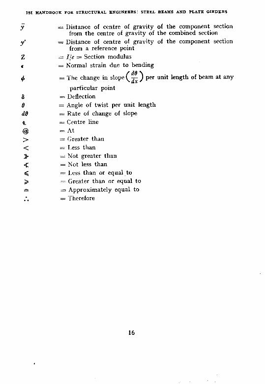
r Y’
z c
4
= Distance of centre of gravity of the component section from the centre of gravity of the combined section
= Distance of centre of gravity of the component section from a reference point
= l/e = Section modulus = Normal strain due to bending
de = The change in slope J-~ ( 1 per unit length of beam at any
particular point = Deflection = Angle of twist per unit length = Rate of change of slope = Centre line = At = Greater than = Less than = Not greater than = Not less than = Less than or equal to = Greater than or equal to = Approximately equal to = Therefore
16

ABBREVIATIONS
Some important abbreviations used in this handbook are listed below:
units
Area in square centimetres Capacity of weld in kilogram per centi-
metre Length in centimetres Length in metres Length in millimetres Linear density in kilograms per metre per square
centimetre Load in kilograms Load in kilograms per metre Load in kilograms per square centimetre -Load in tonnes Load in tonnes per metre Moment in centimetre-kilograms Moment in centimetre tonnes Moment in metre tonnes Moment of inertia expressed in centimetre to the
power of four Section modulus expressed in cubic centimetres
Other Abbreviations
Alright Angle section Bending moment Cerltre of gravity Centre to centre Channel section Dead load
kg/ cm cm m mm
kg/m/cm*
kg kg/m kg/cm’ t
t/m cm-kg cm4 mt
cm4 cm0
OK L BM CG
c/c C DL
17

ISI HANDBOOK FOR STRUCTURAL ENGINEERS: STEEL BEAMS AND PLATE GIRDERS
Equation
Indian Standard Angle Section conforming to and as designated in IS: 8081957
Indian Standard Beam Sections conforming to and as designated in IS: 808-1957
Indian Standard Channel Sections conforming to and as designated in IS: 808-1957
Live load
Neutral axis
Number
Shear force
Single shear
Wide flange beam
Eq
ISA
ISLB, ISMB, etc
ISLC,ISMC,etc
LL
NA
No.
SF
ss
WB
18

SECTION I
GENERAL
‘1. INTRODUCTION
I.1 A beam or girder may be defined as a structural member, usually straight, that has the primary function of carrying transverse loads from specified points in space to specified points of support. An arch also carries transverse loads from points in space to points of support, but the normal stress in the cross-section through the interior of the arch is pri-
lmarily compression. A suspension bridge also carries loads from points in space to points of support but the normal stress in the cross-section through the suspension rope is primarily tension. In the case of the SUS- pended span and the arch span ( considering only vertical loads ) the supporting reactions are inclined with respect to the vertical, hence, depend on a lateral component of force that shall be provided by the foundation. In the case of the beam under transverse loads, the reactive forces at the supports are in the same direction as the applied loads and the normal ‘ bending ‘ stress on the beam cross-section varies linearly from a maxi- mum compression to a maximum tension.
1.2 By far the greatest number of beams are designed to act in ‘ simple .’ bending ’ and the design of rolled sections for simple bending is covered
m Sectior . II. Plate girder design for simple bending is treated in Sec- tion III. Whenever feasible, for greatest economy in design, beam sectiorrs
m’shoufd be chosen, braced ( if necessary ), and oriented with respect to the specified loads so that the assumptions of simple bending 4% justified. 1
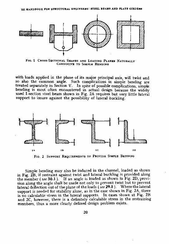
1.3 Simple bending is that type of bending in which the loads and the support reactions are in one and the same plane and the longitudinal axis of the beam remains in that same plane as the beam- deflects. It is assumed that the cross-section of the beam does not twist during deflec- tion. If simple bending is to be insured when an I-beam is loaded in the plane of its web, the compression flange either shall be supported laterally or the permissible stress ( in some cases) shall be reduced to prevent the possibility of lateral buckling. But simple bending occurs naturally, with- out lateral support, in such cases as are shown in cross-sections given in Fig. 1.
In Fig. 1, it will be noted that in each case the plane of the loads coincides with an asis of symmetry of the cross-section. It is important to recognize the conditions under which simple bending will occur and the precautions that shall be observed in design of details and supports for other cases where simple bending is not natural although it may be forced or insured by special means. For example, the channel, used as a beam
19
I~IKANDBOOK FORSTRUCTURAL ENGINEERS:STHELBSAMSANDPLATBGIRL'ERS
FSG. 1 CROSS-SECTIONAL SHAPES AND LOADING PLANES NATURALLY CONDUCIVB TO SIMPLE BENDLNG
with loads applied in the plane of its major principal axis, will twist and so also the common angle. Such complications in simple bending are treated separately in Section V. In spite of possible complications, simple bending is most often encountered in actual design because the widely used I-section steel beam shown in Fig. 2A requires but very little lateral , support to insure against the possibility of lateral buckling.
2n 2s 2c 2D
FIG. 2 SUPPORT R~QUIREYENTS TO PROVIDE SIMPLEBENDING
Simple bending may also be induced in the channel, loaded as shown in Fig. 2B, if restraint against twist and lateral buckling is provided along the member (see 30.1 ). If an angle is loaded as shown in Fig. 2D, provi- sion along the angle shall be made not only to prevent twist but to prevent lateral deflection out of the plane of the loads ( see 29.1 ). Where the lateral support is needed for stability alone, as in the case shown in Fig. 2A, there is no calculable stress in the lateral supports. In cases shown at Fig. 2B and 2C, however, there is a definitely calculable stress in the restraining members, thus a more clearly defined design problem exists.
20

SECTION I: GENERAL
1;4 The primary function of the beam is to carry transverse loads and the ability of the beam to perform its function is judged primarily by the ade- quacy of the beam cross-section at every point, .along the axis to resist the maximum shear and moment that may occur at that section.
In the design of a beam under complex loading conditions the shear fiagram and bending moment diagram are usually plotted (see Fig. 3). It is assumed that the reader is familiar with the determination of such diagrams. Reference may also be made herein to Illustrative Design Examples 1 and 2 and to Section IV.
t 1 MOMENT @.I)
SHEAR (v)
FIG. 3 POSITIVE LOAD, SHEAR AND MOMENT IN BEAMS
1.5 The design of a beam is considered adequate for bending moment and shear if the maximum normal stress due to bending and maximum shear stress due to shear are kept within specified limits that insure a factor of safety with respect to yielding. In simple beam theory, the normal strain parallel to the longitudinal axis of the beam is assumed proportional to the distance from the neutral axis of bending -- an exact hypothesis ( circular bending ) in the absence of shear stress and a close approximation for most practical cases even when shear exists. As shown in texts on strength of materials; the normal stress is given by:
_fb = Er = E+y . . . . . .
21
. . . . . . . (1)

IS1 HANDBOOX FOR STRUCTURAL ENGINEERS: STEEL BEAMS AND PLATE GIRDERS
where fb = normal stress due to bending,
E = elastic modulus in tension or compression, d = normal strain‘ due to bending, + = the change in slope ( de/h ) per unit length of beam at any
particular point, and
Y - distance from neutral axis ( axis of zero normal stress ). In most texts, in place of +, l/R is written, where R is the radius of
curvature. No one is able to see a radius of curvature in nature but, in observing a very flexible beam under load, such as the swaying branch of a tree, one may actually observe deflection, changes in slope and even curvature. Thus, it is intrinsically better to write the equation in terms of 4 rather than l/R.
It is occasionally necessary to calculate the deflections of a beam and a knowledge of 4 all along the beam leads first to a calculation of beam slope at any point - thence ( as will be demonstrated in Section IV ) to a calsu- lation of deflections.
As shown in Fig. 4, 4 is the angle between tangents to the axis of the beam at poinis one unit in length apart, hence, it represents the change in slope per tinit length.
FIG. 4 UNIT LENGTH OF BENT BEAM
To oktain the familiar equation for normal stress due to bending, + in Eq 1 shall be related to the bending moment, M. Below the yield point
22

SECTION I: GENERAL
of steel ( in the elastic range ) there is a linear relationship between bending moment and beam curvature ( a special case of Hooke’s Law ) which may be expressed as follows: .
The amount that a beam bent is proportional to the bending moment. The constant of proportionality, as derived in text books on strength of materials, is EI, the bending stiffness of the beam, and
M=EIcj . . . ..a . . . . . . . . (2)
where
M = bending moment, and I = moment of inertia of the cross-section.
In the limit, if variable, the angle change rate per unit length may be expressed more precisely in the language of differential calculus by introducing :
a’ dy d2y M +=zdg =dxi’= EI
0
fb --=-- Ey . . . . . . .
The interrelationship between deflection, slope, moment, shear, and load may be summarized conveniently by functions of ‘ x ‘, taken as the distance ( to the right ) along the beam:
y = deflection (-assumed positive downward ),
dr -- = slope ( positive when y increases with increasing x ), ax
d2Y M - = + - ( moment assumed positive when normal stress dX2 EI is compression at top of beam) (see Fig. 3 ). . . . (4)
day dxa = -FI ( h p ‘t’ s ear osi ive as shown in Fig. 3 ),/and
d4Y - = + & ( load positive when down ). ax4
For various typical end conditions and load distributions, the solution of Xq 4 to provide equations for deflections, location and magnitude of maximum deflections, etc. reference may be made to any Structural Hand- book.
In conventional, or elastic design, the adequacy of a beam to carry bending moment and shear is determined by limiting the maximum normal stress due to bending, and the average shear stress ( assuming the web to take all of the shear ) to the prescribed ‘ allowable stresses ’ that provide a margin of safety with respect to the elastic limit or yield point strengths of the material.
23

181 HANDBOOK IOR STRCCTURAL ENGINEERS: SIEEL BEAUS AND PLATE GIRDERS
The familiar equation for normal stress due to bending is obtained by combining Eq 1 and 2:
. . . . . . . . . . . . . . . . (5)
If ‘e’ is designated as the distance y to either the extreme top or bottom of the beam, the maximum normal stress due to bending is:
&=T=; . . . . . . . . . . . . . . (6)
Z = f and is termed the ‘section modulus ‘.
The shear stress at any point of the cross-section is given ~by:
f*=~Z . !. . . . . . . . . . . . . - (7)
where
fJ = shear stress, V = total shear resultant on cross-section,
Q = static moment about the centroidal axis of the portion of cross-sectional area beyond the location at which the stress is being determined,
I = moment of inertia of the section about the centroidal axis, and
t = thickness of web.
IS: 800-1956 limits the maximum normal stress on a steel beam cross- section to 1 575 kg/cm2 ( see 9.2 ) and the average shear stress ( when web buckling is not a factor ) is limited to 945 kg/cm2 ( see 9.3.2 ). The average shear stress is calculated by dividing the resultant shear force ( V ) on the cross-section by the gross cross-section of the web, defined for rolled I-beams and channels ( see 20.6.2.1 and 20.6.2.2 of IS: 800-1956 ) as ‘ the depth of the beam multiplied by the web thickness ’ and in the case of plate girders ‘the depth of the web multiplied by its thickness’.
Table I (see p. 169) gives a convenient order for economical selection of the section moduli and shear capacity for the IS Rolled I-beams and channels.
Although not of direct use in design it is desirable to recognize that the normal stress as given by Eq 5 and the shear stress as given by Eq 7 are simply components of the resultant stress that, in general, acts at aw anxle to the plane of the cross-sectim. At the top and bottom of the beam the resultant stress and the normal stress become equivalent, since the shear stress is zero, and at the neutral axis of the beam, where the normal stress is zero, the resultant stress is the shear stress.
24

SECTION 1: GENERAL
2. DESIGN PROCEDURE AND CODE OF PRACTZCE
2.0 The foregoing discussion of simple beam theory presents merely a sketch of some of the more important facts. For a complete development of the theory of simple bending, reference should be made to reference books on strength of materials by such authors as Morley, Timoshenko, or others. Attention so far has been given primarily to bending moment and shear. Beams of normal proportions are usually selected on the basis of bending moment and a routine check made as to their shear capacity. Only in the case of very short beams, or beams in which high concentrations of load near on-e or both ends, will the shear control the design. In addition to shear and bending moment, however, there are a number of secondary factors that need to be checked in any beam design. These will be dis- cussed very briefly in this ‘ Section ’ with complete reference in IS: 800-1956 and actual design details in succeeding sections.
2.1 In some cases, deflection limitations may affect the beam design. A beam that experiences large deflections is a flexible beam and is undesir- able in locations where the loads are primarily due to human occupancy, especially in the case of public meeting places. Large deflections may result in noticeable vibratory movement producing uncomfortable sensa- tions on the part of the occupants and in some cases loading toward crack- ing of plastered ceilings if these exist. The question as to what actual deflection will cause plaster cracking or whether the deflection itself is a primary cause is a debatable one but the usual specification limitations, no doubt, have their place even though they are not usually mandatory.
In addition to a check on deflections, safety against the local crush- ing or buckling of the web of a rolled beam should be checked at the ends and at points of concentrated load. In some cases stiffeners may have to be introduced.
2.2 When the available rolled beam sections become inadequate to carry the load, there are a number of alternatives leading to sections of greater bending moment capacity. One may go directly to a welded or riveted plate girder or, alternatively, flange plates may be welded or riveted to the flanges of available rolled sections. Another possibility is the use of a split- section formed of two T-sections with a web plate welded in between. This will provide a deeper beam section and will require somewhat less welding than a completely built-up plate girder. Other possibilities that should be considered are the use of continuous beams instead of simple beams, or use of plastic design, where applicable. The use of open web beams, tapered beams, or composite beams, offer other modifications of design to provide greater bending strength with the utilization of existing Indian rolled shapes. These alternatives to conventional design are discussed in Sections VI, VII and VIII.
25

IS1 HANDBOOK FOR STRUCTURAL ENGINEERS: STEEL BEAMS AND PLATE GIRDERS
The use of continuous ~beams should be considered in roof construc- tion, for crane runway girders, or for other types of construction in which it is convenient to run the beam continuously over columns or other points of support.
2.3 The possibility of using plastic design becomes especially important when one goes to continuous beam or frame construction. IS: 800-1956 takes some account of the increased plastic reserve strength in bending beyond the-yield point in the fact that 1 575 kg/cm2 4s permitted for rolled sections whereas the stress in plate girders with little plastic reserve is limited to 1 500 kg/cm2. However, in continuous construction, reserve strength is available from another and greater source - redistribution of
-bending moment as ‘ plastic hinges ’ devtlop. The plastic design method may be used advantageously limiting conditions. Reference should be made to the IS1 Handbook for Structural Engineers on Application of Plastic Theory in the Design of Steel Structures (under preparation) for a more complete discussion of this design procedure. Plastic design should probably not be used when repeated loads are an important factor leading to the possibility of fatigue failure. Special attention also may be given in plastic design to modifications in the usual specification requirements for outstanding plate elements under compressive stress since local buck- ling should not only be avoided in the elastic range but prevented in the plastic range up to the inception of strain hardening. However, serious consideration should be given to plastic design of continuous beams and rigid frames of one- or two-storey height when fatigue is not a problem and only a few masimu’m loads are expected.
In the design of beams subject to severe repeated load stressing, the beam near maximum permissible limits with many expected repetitions, such as in the design of a crane runway support girder, stresses should be reduced to prevent possibility of fatigue failure.
Crane runway support beams and beams in similar situations are also subject to impact which sets up elastic vibrations and thereby in- creases the stresses. These additional stresses are taken care of by the use of impact factors and the crane runway support girder serves as a design illustration in Design Example 10.
26

SECTION II
DESIGN OF ROLLED BEAMS
3. GENERAL
3.1 Generally the following are the essential steps required in the selec- tion of symmetrical I-shaped rolled steel beams:
a) Selection for bending moment and shear,
W Lateral support requirements,
4 Design of beams without lateral support,
4 Deflection requirements,
4 Shear stress in beams,
f) Web crippling and buckling, and
g) End connections and bearing plate design. A general discussion of these steps is given in 4 to 10 and is folIowe\
by Design Example 1 ( see 11 ) in which the designs of beams for a specified floor framing plan are presented.
4. SELECTION FOR BENDING MOMENT AND SHEAR
4.1 As pointed out in Section I, the primary function of a beam is to carry load. The moment and shear capacity at every point along a beam shall, therefore, be greater than the actual moments and shears caused by the load. It is assumed the reader is familiar with the calculation of moment and shear diagrams as covered later in Section IV, and with general theory of simple bending as previously discussed in Section I. To facilitate the actual selection of a beam after the maximum moments and shears have been determined, Table I has been prepared listing all of the IS Rolled I-beams and channels in the order of their moment capacity. The index of moment capacity is the section modulus ‘ Z ’ which is given in co1 1 of Table I ( see p. 169). Thus, as will be demonstrated in Design Example 1 after the required section modulus is determined, one may immediately select from the table the beam that will have the smallest weight per metre for the moment capacity needed by following the steps indicated in the note under the table. Except in the case of very short beams or beams carry- ing heavy loads near their ends, moment rather than shear will govern the
27

ISIHANDBOOKFORSlRuCTURALENGINEERS: STBELBEAMSAND PLAIR GIRDERS
design. However, it is convenient to list in the same beam selection table the maximum shear value of each beam in tonnes ( see co1 4 of Table I ). Thus, after selecting the beam for moment one may immediately check its shear capacity. The standard designation of the rolled beam is given in co1 2 of the table and its weight in kilograms per metre in co1 3.
5. LATERAL SUPPORT REQUIREMENTS
5.1 The great majority of beams are designed as ‘laterally supported’ in which case no reduction in allowable stress due to bending is required to safeguard against lateral-torsional buckling. Any beam encased with concrete which is in turn contiguous with at least one adjacent slab may be considered as fully supported laterally. Other conditions of lateral support may be more questionable and some of these are indicated in Fig. 5. Full lateral support should be credited if a concrete slab encases the top flange so that the bottom surface of the concrete slab is flush with the bottom of the top flange of the beam. If other beams frame at frequent intervals into the beam in question, as indicated in Fig. SB, lateral support is provided at each point but the main beam should still be checked between the two supports.
s A CONTlNUaW
AOEOUAlL
INADEOUATE L#TEilAL SUPPORT
FIG. 5 LATERAL SUPPORT REQUIREMENTS
28

SECTION II: DESIGN OF ROLLED BEAMS
5.2 No lateral support should be credited if the concrete slab holds the top flange of the beam from only one side as in Fig. SC, or simply rests on the top as in Fig. SD without any shear connectors or bond other than the surface between the two materials. Temperature change and deflection due to bending will destroy the bond leaving the beam with only friction to depend upon for top lateral support. Similarly, if plank or bar grat- ing is attached to the top flange by means of bolts as in Fig. SE, the support might be temporarily adequate if bolts were firmly fastened and the oppo- site ends of plank or grating securely attached to some other support. However, owing to the temporary nature of the connections, full depend- ence should not be given as there is always a possibility that the bolts might be omitted or -removed. In this case, the design should be made as if lacking lateral support. The matter of designing beams without lateral support is covered in 6.
6. DESIGN OF BEAMS WITHOUT LATERAL SUPPORT
6.1 When special conditions require that a beam be loaded in the plane of the web, without continuous or intermittent lateral support at sufficient- ly frequent intervals, the beam will ultimately fail by buckling with lateral and torsional deflections. In order to provide adequate safety against such buckling, the allowable stress is reduced in certain cases. The reduc- tion in allowable stress increases with increasing Z/b ratio and d/ff ratio where :
1 = unsupported length of beam, b = width of flange, d = depth of beam, and 6 = flange thickness..
6.2 Permissible stresses are tabulated for* various ratios in Table II of IS: 800-1956. The formula on which these values are based is given in Appendix E of IS: 800-1956 and tabulated values apply only to rolled beams of constant cross-section and of symmetrical I-shape. The formula? mav be applied to channels with over-safe results. For beams with vari- ablk flange-shape, unequal flanges, etc, reference should be made to Appen- dix E of IS: 800-1956.
6.3 In certain parts of the tables in IS: 800-1956, it is difficult to inter- polate properly. To overcome this deficiency elaborate tables showing permissible stresses for closer intervals of Z/b ( or Z/r, ) and d/if ( or .d/t, ) (see Tables II and III on p. 172 and 174) are given in this handbook. Examples of the application of Table II are given in Design Example 1. Example of the application of Table III is given in Design -Example 10.
29

ISI HANDBOOK FOR STRUGTURAL ENGINEERS: STEEL BEAMS .4ND PLATE GIRDERS
7. DEFLECTION REQUIREMENTS
7.1 Recommended deflection limitations for beams and plate girders are given in 20.4 of IS: 800-1956. When rigid elements are attached to beams or girders, the specification calls for a maximum deflection of not more than l/325 of the span. However, this may be exceeded in cases where no damage due to deflection is possible.
7.2 If a structure is subject to vibration or shock impulses, it may be desir- able to maintain reasonable deflection limits such as will produce a stiff structure less apt to vibrate and shake appreciably. For example, exces- sive deflection in crane runway support girders will lead to uneven up and down motion of the crane as it proceeds down the building. Impact stresses in such case would be increased.
7.3 Possibility of excessive deflection will arise when a rather long span carries a very light load for which a relatively small beam size is required. Such a situation might esist, for example, in a foot bridge. The matter of deflections is very largely left up to the judgement of the engineer.
7.4 Very long beams subject to large deflections, such as the open joist type, are usually cambered so that unsightly sag will not be noticeable when the beams are fully loaded.
8. SHEAR STRESS IN BEAMS
8.1 The subject of shear stress.has been discussed in Section I. It is to be noted that in the case of rolled beams and channels the design shear is to be figured as the average shear obtained by dividing the total shear by the total area of the web computed as (d) (t,J. In more complex beam problems such as those with cross-section unsymmetrical about the X-X axis, the more exact expression for the calculation of shear stress or shear per running metre shou.ld be used. The more exact expression should also be used in calculating horizontal transfer of shear by means of rivets or welds. The design example will illustrate these calculations.
9. WEB CRIPPLING AND BUCKLING
9.1 When a beam is supported by bearing pads or when it carries concen- trated loads, such as columns, it shall be checked for safety against web crippling and web buckling. stiffeners need not be added.
If the beam web alone is adequate, bearing Web crippling is a local failure which con-
sists of crushing and local plastic buckling of the web immediately adjacent to a concentration of load. The load is assumed to spread or ‘disperse’ at an angle of 30” ( see 20.5.4 of IS: 890-1956 ) as it goes through the flange and on out to the flat of the web at the line of tangency to the flange fillets.
30

SECTION II: DESIGN OF ROLLED BEAMS
The bearing stress of 1 890 kg/cm2 that is allowed may result in minor localized plastic flow but provides a safe and reasonable basis for checking the design of this detail. In addition to the possibility of local crushing or crippling there is also the problem of general buckling of the web plate above a support or below a localized load. The web is assumed to act as a column with reduced length. A beam that is safe with respect to web crippling will usually be safe as well with respect to this type of web buckling.
These and other details of the design will be demonstrated in Design Example 1.
10. END CONNECTIONS AND BEARING PLATE DESIGN
10.1 If the end of the beam is supported directly on masonry without bearing plates, the local bending strength of the beam flanges should be checked to make sure that they may transfer the load from the local region under the web to the outer parts of the flange. The flanges of the beam act as small cantilevers to carry the permissible allowable load transmitted by the masonry without excessive stress. With stress thus limited they will be rigid enough to distribute the load to the masonry. If the flange were bverstressed in bending, the load would be concentrated immediately below the web and local crushing of the masonry with possible subsequent cracks would result. The connection of the end of a beam to a column or girder may be either by means of web angles or top and bottom angles or by a combination of both. When a web angle connection frames to a beam or column web with beams entering from both sides and utilizing _common rivets or bolts, it is desirable to add erection seats since it is difficult to hold both beams in place while rivets or bolts are being fitted. In general the engineer should carefully visualize just how the beam will be put in place during erection and make sure that a proper choice as to field or shop rivets is made so that erection will be facilitated. In the case of welded connections, there shall be provided a simple bolted erection plate or angle to hold the beam in place while field connections are being welded.
11. DESIGN EXAMPLE OF ELOOK BEAM FRAMING
11.1 The illustrative design example of floor beam framing showing the design of rolled beams is worked out in the following 17 sheets ( see Design Example 1 ).
31
ISI HANDBOOK FOR STRUCTURAL ENQINERRS: STEEL BEAMS AND PLATE GIRDERS
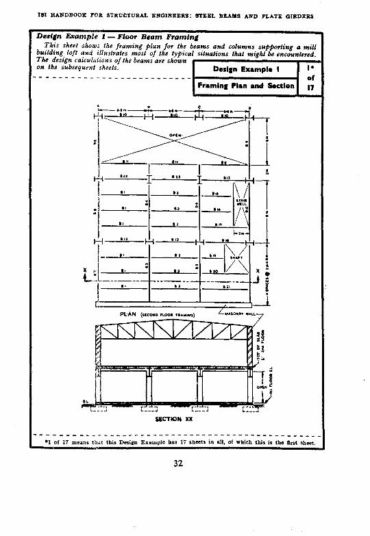
Design JLvampk 1 -Floor Beam Framing This sheet shows the framing plan for the beams and columns supporling a mill
building loft and illustrates most of the typical situations that might be encountered. The design calculations of the beams are shown on the subsequent sheets. --------A . . .._ _ ___-__-_--__-
Framing Plan and Section
______________L------------------------______
l l of 17 means that this Design Example has 15 sheets in all, of which this is the first sheet.
32

SECTION II: DESIGN OF ROLLED BEAMS
Initially, this sheet presents loading requive- Design Example I 2 men@ for both dead and live loads. In addition to the. distributed live loud of 735 kg/m”, Ihe
of
design is lo include consideration of a S-tonne Design of Beams B, L B, 17
‘roving’ load !hat may be placed ovel a~ - 1.5 x 1.5 m area. ( Thas will permit the installation of a heav)r piece of nrachiurry ON the poor but will rule out putting two such pieces of equipment uz close proximit~v.) The $vst beams that shall be designed aye those that do not receive reactive loads from other ~beams framing into them. Since Poor dead lo& and tire distrtbuted live load bolh contribute uniform load per lineal metre to beams B, or H,. the bending moment due to this load is calculated separately. The ~roviwg distributed load of 5 tonnes is first placed at tke centre of the beam for maximum mometrt. The concrete slab encloses both sides of the top flange thereby providing. adequate lateral sltpport and the full permissible stress of 1 575 kg/&* is permitted. The required section modulus is then determined and by reference to Table I (see p. 169) it is immediately seea that 1SI.B 450 beam would be satisfactory. The maximum sheav is checked by mot&g the roving load to the end of the beam.
_______-_-_------_-_-.S---_________________-----
Sketch on Sheet 1 shows a plan and cros&ctional elevation of an industrial building. The end floor will carry a 12-cm HCC slab with 2.5 cm wearing surface added and will be designed for a live load of 735 kg/m* plus a 5-t load that may be ~placed over a 1.5 xl.5 m area in any location. Exterior wall beams will support 670 kg per lineal metre in addition to any tloor load they receive. The stairways are to be designed for 735 kg/ma.
Use IS: 800-1956 BEAM B, or B,
DL of slab ( including wearing surface ) = 370 kgjm’
Live load = 735 kg/m* 1 105 kg/m*
Load per metre length of beam being spat- 1 105 x 2 ed at 2 m apart = -___
Assume beam weight = 75 kg/m = 0.075 t/m
BM a Q. _ w; ._ 2.285 Xi.5 x6.5 _
07 1 206 cm-t 5x6.5 2.5x0.75 Due to roving load, BM @ Q = -Tx2 - ._2._._
= 7.188 m.t OY 718.8 cm% Provide iateral support
Toti1 Max bending moment, 1 206+719 =: 1 925 cm+
Required 7: z % .= L:LYF! = 1 222 cm* fb
able I: Choose ISLB 450, 65.3 kg _ 1 223.8 _ z
Check shear value
V 2.285 x 6.5 ’ 5 x 5.75 mar .z= -__-- - _6-5
2 = 11.85<36-6t.....dK.

ISX HANDBOOK FOR STRUCTURAL ENGINEERS: STEEL BEAMS AND PLATE GIRDERS
Beam B, may now be designed since the zactions it receives as lands B, and B, 01 simi- ar beams have now been determined. These ,eactions aye introduced, however, without the oving load since thtzs will be moved directly on he beam B, in its des,ign. The required-sec- ion modulus of 4 432 cm3 turns out to be higher than cozy IS r&led sections. One nay either use an zmported beam of greater deptk o strengthen ISWB 600, 145.1 kg section.
QY add t$ artd bottom covev platea This latter course is adopted and the
stimate of dead weight of the beam Itself is revised. It ,is noted that when the sec- ion is deepened by virtue of the welded plates. the coutribution of the ISWB 600 to he total 2 value is reduced and the reduction is estimated b.v multiplying by the ratzc If depths before and after weldirtg the cover plates. noment of inertia procedure.
Firral desbgn check wzll be by
------------------_------~~---~-~- _- ____ ------
1ombined B, and B, reactions ( without roving load ) = 2.285 x y x 2
-14.9 t Assume beam weight = 140 kg/m MaxBMis@ 4 0.14 x (8)* M, ( due to beam weight )= -._ =
8 1.1 mt
MR =“4& - 14.9(2) = 59.6 mt
BM (roving load) = 2.5 ~4-2.5~~2 = 9.1 m.t
M, ( total )
2 required
No rolled section is available with this section modulus, so an ISWB 600, 145.1 kg section with welded cover plates ( top and bottom ) will be adopted.
L
= 69.8mm.t 6 980000 = -__ = 4432cm’
1 575
Assume new weight of beam with cover plate
M, - 0.28(g)*
= 200 kg/m
= 1.6 met
M: = 1.6+59*6+9-l = 70.3 mt
z _ 7030~ 1 575
= 4 460 cm3
Assuming that 1 of 2.cm thick cover plates will be required, the approximate i contributed by ISWB 600, 145.1 kg will be;
3 854 ‘< 60. = 3 700 cm3 ’ 62.4
’ . . 2 in required plates = 4 460-3 700 = 760 cm8
Approximate area required in one-flange plate 760 zz- 2x31
= 12r3

SECTION II: DESIGN OF ROLLED BEAMS
In order to determine the length covey plate that is required, itt view of the roving load. at is now necessary to draw to scale the envelope of various moment diagrams that aye possible with the rovrjzg load zn diffrvent positions along the span. The r~~velope of betiding moment dia- gyams. plotted at the bottom of this sheet, indicates that the theoretical length of the cover plates will be about 2.26 m but in order to develop the plate at its ends it is cu’stomary to add a ltttlr more at each end making the total length ap$voximately 2.8 m.
Lexgth of Cover Plate
A quick method which is accurate enough for practical purposes is to draw the diagram of ‘maximum moments’ and scale’the points which the ISWB 600 may take in moment.
Trial loadings for maximum moments with roving loads at 4, 4 and Centve Points of beam
The maximum moment at a section is %ahen the roving load is at the Section.
Assume dead load = 200 kg/m
&2,=0.2(4)(2)-0.2(2)(l) = I.2 n&t
R, = 22.35-15 xi = 25.47 t
BM (at 8 point) = 25.47(3)--2.5 y -14.9~1 ( >
= 60.57m.t
M,,(at # point) = MD+60.57 = 1.2+60.57 = 61.8 m.t
Total Max B&I at Centre Point, M,3 (see Sheet 3) = 70.3 mt
3 854x1 575 ISWB 600 moment capacity= looxlbm = 60.6 m.t
Theoretical length required = 2(1.13) = 2.26 mt
For making allowance for the customary extra ENVELOPE OF THE BENDING hfo&lENr DIAGRAM SINJWING
length required on either side, adopt 2.8 m. THEORE+KAL LENGTH OF COVKR PLATE REQUIRED
35

IS, HANDBOOK FOR STRUCTURAL ENGINEERS: STEEL BEAMS AND PLATE GIRDERS
Flange plates 19.0 x0.6 cm ave tried and the moment of inertia calculated. The welds attaching the cove? plate Io the beam shall now be determined and since the weld requirement is a function of maximum shear. the roving load is put in a posilion Bat will produce Ihe maxi- mum shear near the end of the cover plate. The horizontal shear to be transferred is determined by Eq 7 (see p. 24) [nwlriplying both siaks by t to obtain Ihe total shear Ivansfev (fs) per linear centimetre]. ______________---___--~~-_--~~______-~~_~--~~~~
Approximate area required in each cover plate (see Sheet 3) = 12.3, cm*
Try 2 plates, 19-O x 06 cm
Area of one plate = 11-4 cm*
I of cover plate = 2(11.4) (30.3)’ = 21 000 cm’
I of ISWB 600 = 115 627 cm’ Total = 136 627 cm4
zr = 136 627 - = 4 470 cm*>4 460 required . . . . . OK.
30-6
Determine Vmax @ location 1. (This is approximate calculation and is con- n.O(
sidered OK for practical purposes.)
Vmar = 22.35+5x5$ / I
= 25.63 t -*nr----rl”----s.asa -?
Appioximate total weight of section 145+18= 163 kg/m Total Vmax = 25.6+4(0.163) = 2625 t
Actual horizontal shear per linear centint@e:
VAcY 26.25x11.4x30.3 -_= I 136 627
=i 0.066 5 t/cm
Use 6.0-mm fillet weld intermittent (see 6.2.2.1 & Table I of IS: 810~1956). Working load/cm length = 6(0.7) (1 025)
= 430 kg/cm (referring to 6.2.3, Table II, 7.1 and Table III of IS: 816-1956)
Minimum length of weld = 4 x 6-O = 24 mm (see 6.2.4.1 of IS: 816-1956) Use 2.5 cm length
Working strength of 6.0-mm weld 25 mm long, 2 sides = 2 x 2.5 x430
= 2 150 kg w 2.1-S t rcovrn CLlTl
c/c spacing = x
O-066 5 X = 2.15 \ I I rJ
iL-4i X = g55324 cm
l---x--l S = 32.4-25129.9 cm
36

SECTION 1,: DESIGN OF ROLLED BEAMS
Since it is uneconomical of the welder’s time 1s well as being less eficient to start and srOp rew welds, the length of weld in each intermittent ,ection should be as long as possibie ilt keeping vith the requirement of the space thickness patio. Thus. in the light of all of these factors. / ?.5 cm long 6-mm fillet welds spaced 18-S cm centve to centve are chosen. At the en, If the plate, a continuous weld fov a 16cm length o.f plate is used so as to fully develop he cooev plate at the poi?zt where it begins to be needed.
Required S by6.2.6.2 of E:816-1956 So that S/t < 16 S = 16 (0.6) = 9.6 cm < 29.9 cm
‘Ience adopt 9.5 cm clear spacing. weld strength at ends of cover Ilate to develop strength of plate Isee 20.51 of IS: 800-1956):
Plate strength = 0.6 x 19 x 1.575 = 17.96 t
SECTION XX
L - ‘7% 0.43
= 41.75 cm
41.75 -19’ -~- = 11.37 cm,
‘5 ov say 12 cm PARTIAL PLAN It may be observed that with 6.0-mm intermittent fillet weld at 2.5~cm lengtl
though the required spacing is 29.9 cm clear, the minimum Code (IS: 816-195f requirement of 9-6 cm corresponding to O-6 cm thickness of cover plate has to t adopted. Thus, there is still some waste in weld. Also some special precaution are to be taken while welding (see 6.2.5 of IS: 816-1956). These may be overcon by redesigning the cover plate thickness.
Choose 2 plates of 12.5 x 1.0 cm. Area of 1 plate = 12.5 cm’ Z of cover plate = 2 (12.5) (30.5)’ 5 23 256 cm’ Z of ISWB 600 = 115 627 cm’
138 883 cm4
z = 138 883 = 4 30.8
480 ems > 4 460 cm* required.
Using 6.0-mm weld at 25 mm length, the required spacing as worked out i ready is 29.9 cm clear. Code requirement = 16 t = 16 (1-O) t = 16.0 t
Use a clear spacing of 16 cm.
= 14.62 ov 15 cm length to be welded
____-_---___-____--- ______-_-_--___-_-_--m-o-- *Width of cover plate.
37

ISI HANDBOOK FOR STRUCTURAL ENGINEERS: STEEL BEAMS AND PLATE GIRDERS
The beam is assumed to rest on a bearing plate set in the masonry wall with an assumed length of bearing equal to 15 cm. Similarly, at the opposite end, the beam rests on the 15 cm outstanding leg of a seat angle. At either end the check as to web cvushing ov crippling is similar and the sketch shows how the load is assumed to be dispersed upwards from the bearing plate through a distance equal to the jange thickness plus the @let radius for a distance h,= 4.6 cm. Thus, the total effective length of web resisting local trip- pling is found to be 22.9 cm. The bearing stress is less than that permitted by the specification so we now turn to a check on the web buckling. The speci+cation stipulates that no bearing stiffener is needed at points of local support provided the buckling re- quirements are met. The beam is found to be amfily strong with respect to buckling to resist the maximum end reaction of 27.53 tonnes without any bearing stiffeners. -__------__-------_______________________------
Check web crushing (crippling)
Angle of load dispersion = 30” (see 20.5.4 of IS: 800-1956) Referring to Table I of IS1 Handbook for Structural Engineers: 1. Structnral Steel
Sections h, = depth of intersections of web to flange fillets = SO.79 cm
h, = 4.6 cm b (see sketch above) = 15;4.6 cot 30” = 22.95 cm Vmax= 27.53 [see Sheet 6); Web thickness, tw = 11.8 mm
Bearing stress = 27.53 x 1 000
(22’95) (1’18) = 1 015 kg/cm’ < 1 890 kg/cma
(see 9.4 of IS: 800-1956)
Check fov buckling Allowable reactions with no stiffener = FctB (see 20.7.2.1 of ISP800-1956)
SO.79 _ l/r = m1/3 = 64.5; F, = 1 068 kg/cm’
Assuming 13 cm as stiff length of bearing for 15.0 cm seat angle:
B = 13+ y = 43 cm; Allowable R = 1068 (1.18) (43) =54>27.53.....0K.
Buckling strength at masonry support is safe, the stiff length of bearing beini: 15 cm > 13 cm.. . OK.
38

SECTION II: DESIGN OF ROLLED BEAMS
On the assumption thal the designer wishes to comply with the optional specificalion ve- quivement that the allowable deflection be less than l/325 of the span length, this deflection is now calculated and is found to be well within the requirement. The& the bearing plate at the
.
masonry suppovled end is designed. For the 15-cm length of bearing used, a 34-cm width is required. It would be more economical to use a more nearly square plate, requiring a smallev thickness, but it has been assumed that fhe available bearing length is limited lo 15 cm. There is tao question of failure but it is desired to provide a bearing plate stiff enough lo spread fhe load to the masonry and prevent local cvachs.
Loading sketch for maximum deflec- tion is shown here.
Assuming 5 t load as a concentrated load, the loading may be considered as 14.9 t, 19.9 t and 14.9 t.
Pl’ Due to central load & = __
48 EI Due to the two quar-
ter point loads & = $& (3P -4a*)
13 000 tons/in.‘) E = 20.5 x 10” kg/cm% (corresponding to By Method of Superposition:
19.9 x (800)3 x 1 000
F = 48 (2 050 OOCJ) 137 953 - 2:$$2~;l13;~3.(3 x800” - 4 x 200’)
= 1.52 cm Limiting deflection = l/325 span (see 20.4.1 of IS: 800-1956)
800 - = 2.46 > 1.52. . , . . OK. 32.5
Beam bearing plate
Assume allowable masonry bearing stress = 55 kg/cm*
Area required = ig = 500 cm*
B = $) = 33.3 cm, OY say 34 cm
b = 1.18+2 (4.6 cot 30”) (based on 30” dispersal of web load through flange plus fillet)
= 17.15 cm
= 54 kg/cm”
p1 = 27.53~1 --- __ 000 = 107.1 kg/cm* 17.1 x 15
M@Q = 17 (54) (8.5)- ‘q (107) = 3 929 cm.kg (taking a l-cm strip)
M/I = f/y and f permissible 1 890 kg/cm* (see 9.2.3 of IS: 800-1956)
1 890 = ___, 929 t/2 01 t = 3.53 cm 3 P/12
Use 15 x 34 x 3.6 cm bearing plate.
39

ISI HANDBOOK FOR STRUCTURAL ENGINEERS: STREL BEAMS AND PLATR GIRDERS
o_f beam II,, the liae load zs erzttrely omitted as the maximrcm positive bending moment muld be for fhis rondttiotz. .4 t the zlzterior column, reaction point, designated as R,, the framed ends of beam B,, provide a partial stiffener and it will be assumed that local web buckllq will be preve,rted. The bearing plate between the column and the beam will not be designed as reference may be made to ISI Handbook for Structural Engineers 3: Steel Columns and Struts for the design of similar bearing plates at a colunrlt base. _-----_---_______________-~-------~-------~--~~~
tb.St slltCJt MC1 ( It may ‘be noted that the beam loads at the supports are not shown as these will not affect the BM and SF diagrams.)
bm
.4ssume B,, weight= 20 kg/m BEAHWT N.9t l&¶l
Dead load of slab = 370 kg/ma (set Sheet 2)
B,, reaction ( from two sides) = 2(2) (6.5)
------370+20x6~5kg 4
= 2.54 t Assume B, weight as 200 kg/m
R, = 200x3~10
8 = 750 kg
R, = 1 250 kg B&f at midway = 0.750~400 - 0.2~4~200 between supports = 140 cm-t
R, due to other loads = 3(14.9)(4)$-j(4) -2.54(2) = 25.49 t 8
M# due to other loads= 25.49(4) -14.9(2) -2.5(0.375) = 7 122 cm:t kit due to B, weight = 140
Use IS\VB 600, 133.7 kg with cover plate. shown here.
Design of cover plate will not be It may be noted that in the design of beain B,, the area required
in the cover plates was small, as ISWB 600, 145.1 kg was adopted, and resulted in uoeconomical welding details. cover plate is recommended,
Hence for beam B,. ISWB 600, 133.7 kg with This will also result in a lesser overall weight of
&am B, than when. ISWB 600, 145.1 kg with cover plates is used. Beam B, also could be designed with IS\VB 600, 133-7 kg with cover plates. Check shear value.
The loading sketch for maximum shear at B,, is as shown above.
Y,,,al = R,-2-54 = l-2%(3 x 19.9 x 4+5 x 7.25) -2.42(2) -2.54
= 28.8 < 63.5 t ( Shear8capacity of ISWB 600, 133.3 kg) Check web crushing
It may be noted that for maximum shear in B,. the reaction of beam B,, should include live load which was omitted while determining the maximum possible moment on B,. The maximum shear with this correction is 38.4 tonnes ( see Sheet 10) which is still less than the shear capacity of the beam ISWB 600 de- signed _ _ _ . OK.
40

SECTlON II: DESIGN OF ROLLED BEAMS
In checking the local web crippling at R, kc full live load is inlroduced inlo Ihe reaction
Design Example I IO
tf B,, as this will produce Ihe mnninrum R, Beam B, - Bearing of
peaclion. The bearing stress in the web is xmsiderably less than tke permissible value.
Stress in Web I7 __--__-__------ _--_-_---_-
hssuming ISHB 300 as shown in the sketch at the bottom, for the column:
Load dispersion = 30” (see 20.5.4 of IS: 800-1956 ) h, = 2.51 cm ( see T;hle 1 of ISI Handbook for Structural Engi-
neers: 1. Structural Steel Sections ) b = 30+2(2-S cot 30” ) = 38.7 cm
Reactions on this column will include BIS reactions, as they frame into B, at this SUppOrt.
The two B,, reactions approximately = 14.9 t ( same as B, )
For Max R,: The %e&tion from B,, should include live load also. Due to dead load = 2.5 t ( see Sheet 9 )
Due to live load = ‘v 0.735’= 4.8 t
R,
Total R
Total = -x
= [3(14~9)(4)+5(9~25)+0~2(10)5+7~2(10)]+8 = 38.4 t = 384+14.9 = 53.3 t
53.3 x 1 000 Bearings- = 38.7x1.12
= 1 542 kg/cm* < 1 890 kg/cm* permissible . . . . . OK.
Buckling load not to be checked due to stiffening effect of B,, connections. Check section for moment at cantilever.
Assuming no cover plate at cantilever support:
w = @l-34 t/m ( weight of ISWB 600, 133.7 kg ) M = 7*3(2)+@134(2) 1+5(~1.25) = 2 152 cm.t z ~2152x1000
1575 ~1370cm~<3540cmS.....0K.
.----_____________---- --__-_-_-___________------ *Live lord.
41

ISI HANDBOOK FOR STRUCTURAL ENGINEERS: STEEL BEAMS AND PLATE GIRDERS
The design of beam B, introduces the problem of the lack of lateral support. Fov 6 m. this beam sufiports the exterior wall but has no effeec- tive lateral bvacing because it is adjacent to the open area at the end of the building. Beam B,, provides effectivr lateral bracing-at a point. Thus. while the bending moments are calculated on the basis of the full 8 m length an effective length of 6 m is used to determine the permissible stress. ---__-_ - ----- - ---_-- --- --__ -__ ---- -----------_ - -
The 5-t roving load is first distributed to B,, and B,,,
B,, share is y
The effect of this x;z on B, is 5x1.25xE
2 6 B,, reaction on B,
z ?+5( g?)(g) = 6.5 t
Exterior partition load = 670 kg/m
Assume beam weight = 75 kg/m
Uniform load = 745 kg/m R, = V, = 65 (:) + 0.745 x4
= 4.87+2.980 = 7.85 t M max=7.85(2) -0.745(2) (l)= 14.2 m.t EffectiGe 1 = 6 m ( unsupported span
against lateral bendmg ) Try ISWB 400, Z = 1 171.3 cma; S = 32.5 t
l/b = $$+= 30; tf = 13.0
b = 200 wt = 66-7 kg/m 400
d/tf= w. = 31
Fb = 1 142 kg/cm2 ( see Table II on p. 172)
Required Z = 1 420 000 = 1 240 m cma > 1 171.3 provided by ISWB 400.
Hence another trial.
Try ISMB 450, 724 kg ( The next higher section from Table I on p. 169 )
l/b = &; =40 d/tf =g4 = 26 F, = 889 kg/m2
Required Z = 1 ------=1600> 420 000 889
1350*7-NoGood.
Try ISLB 500,750 kg; Zx = 1 543.8 V = 43.47 wt = 75.0 kg/m
if = 14.1 mm b = 180 l/b = !;8v z 33.3 dltf = ;- = 35.7
~ Fb = 927 kg/cma ( see Table II ou p. 172 )
Required Z = __~~~- 1 420 000 = 927
1532 cmS~< 1543 . . . OK.
Beam weight assumed previously is OK.

SECTION II: DESIGN OF ROLLED BEAMS
Border beams B, and B, are now designed. These cavry end reactions from beams B, amounting to half of the similar loads on beams B, and B,. These beams also carry the exieriov wall and they aye not assumed as completely supported laterally, since the Joor slab encases orrly one side of the flange. However. on the basis of the unsupported length of 2 m, no stress reduction is found necessary.
Beams B,,, B,, and B,, will now be de‘signed in sequence. Although these do not introduce selection problems, they are included to illustvate the calculation of loads and reactions on interrelated beams. The design of beam B,, is routine.
---________----_-__-___________________~__-~___.
Assume beam weight = 130 kg/m Exterior partition load as in
Sheet 11 = 670 kg/m Total uniform load w = 800 kg/m
M W
= 800x8’x100 8
= 640 000 cm.kg
BM (due to B, reactions) = 11.1 (4) -7.4 (2) = 2 960 000 cm.kg BM (due to 5 ft
roving load) = 2.5 (4)-2.5 (0.375) = 906 300 cm.kg BM (total) = 4 506 300 cm,kg
Effective length = 2 m It is likely Fb E 1 575 kg/cm* as the beam is supported laterally at fairly close
intervals. 4 506 300
Required Z = -~1575 = 2 860 cm*
From Table I on p. 169, choose ISMB 600, 122.6 kg Z = 3 060.4 b = 210 tf = 20.8 mm
l/b = g = 9.5 600
d/tf = W8 = 29
From Table II (see p. 172) F, = 1 575 kg/cm2 as assumed. Hence OK.
Check shear value
v = 11.1 + C.800~4 + 5 (7$)
= 19t <68.0t.....Q
& POSITION OF LOAD FOR MAX MOMENT
POSITION OF LOAD FOR MAX WEAR
ic.
Beam B,, Assume beam weight =
w = (Dead load + Live load, see Sheet 2) =
Total =
(Routine design) Use ISLB 325,
60 kg/m
2 210 kg/m
2.27 t/m
43.1 kg.
43

ISI HANDBOOK FOR STRUCTURAL ENGINEERS: STeEL BEAMS AND PLATE GIRDERS
Since beam B,, is adjacent to the stair well and carries a floor stab on one side only, it is
I Design Example I I3
assumed that the unsubfiorted lenpth is 2 tn. of Beam B,, is of intevesi6ecause of ‘ihe loading. I& is assumed that a stairway starts at this level
Berms B,, L B1,
and PUWS to the ground poor below. Thus, at an assumed dead load plus Iive load of 1 200 kg/m’ one;half of fke total supported stair load is assumed to rest 2 m from the end of beam B,,. Although the skeav and moment diagram for this beam might well have been drawn, it is quicker to calculate the bending moment at the centre line and at the point of load concenfration. One of these two will be very close to the maximum and wilI be a satisfactory basis for design.
Beam B,, B,, reaction (due to
dead load and live lo&d ) = 2.25 (2.27)
R2 = 5.11 t
Use ISLB 450, 653 kg.
Feam B,,
Assume beam weight = 90 kg/m Stairs: DL+LL = 1 200 kg/m*
1 200 x 6/2 ( see plan
on Sheet 1 ) = 3 600 kg/m t panel load ( see
Sheet 1 ) 1 (1 105) = 1 105 kg/m Total = 4 70.5 kg/m
Case 1 GJ B: 014.7 t/m
R, = 2.2 (4.5) ‘$
= 12.4 ; ( )
4-2.5+=6(~)+4.7(2.0)(;)+0+39(~)
BM = 12,4 (3.25) - (2.2 + 0.09) (y) (y) - 2.5 (0.37)
= 27.0 n1.t
Case 2 @ B,, reaction point:
R, = 2.2 (4.5) ( )
‘g I- (5+5.36)&i- 0.09 (y) + 4.8 x 2x1
6.5
= 11.4 t BY = 11.4 (4.5) - 2.2 + 0.09 (4.5) (2.25) - 2.5 (0.375)
= 27.2 m.t

SBCTlON 11: DESIGN OF ROLLED BEAMS
The beam unsu##wted stairway.
selected for B,, is checked for an
I
Design Example I
I
I4 length of 2 m adjacent to the of
Beam B,, 17
Assume Fb = 1 575 kg/cm* as the unsupported length is 2 m in the stair well,
2720000 Required Z =1575
= 1 733 cm*
Try ISLB 550,
Zr = 1 933.2 cm*
w = 86.3 kg/m
b =‘190 mm
tr = 15.0 mm
a& =$. = 33
Fb = 1 575 kg/cm’ as assumed . . . . . OK.
Check skcar as before
45

ISI HANDBOOK FOR STRUCTURAL ENGINRBRS: STEEL BEAMS AND PLATE GIRDERS
Typical riveted conneclions will now be designed for the poor framing plan of this example. Generally speaking, welded connec- tions offer somewhat greater weight saving in steel than do rzveted but sirrce this wills be covered in ISI Handbook for Structural Engi- neers on Deszgning and Detazling Welded Joints and Connections {under preparation), the connections in lhis example will be riveted. This design sheet shows the proposed arrangement for a stijfcned seal wzlh an inverted top cleai making Ihe top of the column flush with the top of the beams neay the bottom of the concrete floor slab. Permissible rivet stresses are compuled on thzs sheet.
DESIGN OF CONNECTIONS
CONCRETE FLOOR
LA SECTION AA SECTION BB
Rivets: 22.0 mm (or 4 in. dia)
Gross area of rivet cc!? = 4.2 c*nl = 4x100
Rivet values (see 10.1 and Table IV in IS: 800-1956) Shop (power driven) single shear = 4.2 (1 025)
= 4 300 kg Double shear = ‘2 (4 300) = 8600kg Permissible rivet bearing stress = 2 360 kg/c& Field (power driven) single shear = 4.2 x (945)
= 3 969 kg Double shear = 2 (3 969) Permissible rivet bearing stress
= 7 938 kg = -2 125 kg/cm*
46

SECTION II: DESIGN OF ROLLED BEAMS
Beams B, and B, carvy their load into the wlumn web by rivets common to both stiffened seat connections. Thus. these vivets have to transmit approximately twice the end reaction of either beam B, or B, and they are so calcu- lated. The stiffened seat connection as shown in Sheet 15 consists of a horizontal cleat with two vertical cleats acting as stiflener. It is xecessary to introduce packing or filler plates equal in thickness to that of the horizontal seat angles.
____-____i__-____--- -__-__-------- ________ - ____-
Maximum reaction of either B, or B, = 27.5 t (see Sheet 6)
Combined reaction transmitted to column = 2 (22.3) + 5 = say 50 t
Investigate first the column web in bearing, as this appears to be the most critical condition due to thin column web.
Nom-The reaction due to B,$ beams are not included here as these will be connected to column flanges dmctly and not to web of column section through B, or 8,.
Column is not designed in this example, so assume a column web, tr = 1.0 cm
No. of rivets to column web = = 9.5 = say 10
Minimum thickness, t, required for any member of connection ( angles, packing, etc ) is found as follows:
t (2.3) (2.125) = 3.97 (field rivet bearing against single shear)
NOTE - This is in accordance with good practice.
t = (2.3;;125) = 0.8 cm
For shop rivet, t = (2.3~~~60j = 0.79 cm, use O-8 cm for all cases.
Additional rivets for packing as required by 24.6.1 of IS: 800-1956.
c6 (2) = 10 percent, extra rivets required w = 1 rivet
Ilut, for the sake of symmetry, use 6 rivets in the extension of the packing as required in 24.6.1 of IS : 800-1956. We have already assumed 15.0 x 15.0 cm seat angle in Sheet 7. For adequate stiffening of the seat angle, you require at least 125 X 75 mm angle stiffener. The minimum thickness being 8 mm as cal- culated above, use 2 of 125 x 75 x 8.0 mm angle sections on each side of the column web. Effective length of outstanding leg = 125-10 = say 115 cm. Bearmg capacity of 2 legs (outstanding) = 2(11.5) (0.8) (1.890) = 34.78 > .27.5 t.
Check rivet capacity of stiffener leg = lO(4.3) = 43 > 27.5 t . . . . . OK.
As cleat angles on top are only for lateral restraint, use a reasonable size, say 2 of ISA 10075, 8.0 mm. Dimensions of packing are determined by minimum pitch 01 rivets and edge distance requirement_ (see 25.2.1 and 25.4 of IS: 800-1956).
47
191 HANDBOOK FOR STRUCTURAL RNGINBRRS: STEEL BEAMS AND PLATE GIRDERS
An alternative tvpe of framed connedion for k same location is designed. This is the rireb
Design Example I I7
kal angle connecfion as shown. Since bolh Alternative Connections of
earns have common rivek framing to the olumn web it is not possible to erect them indi-
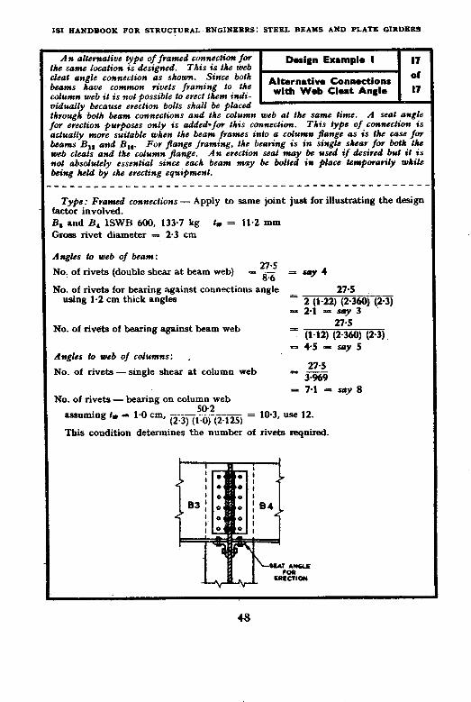
with Web Clut Anglo 17 idually because erection bolts shall be placed ’ hrough both beam connections and the column web at the same time. A seat angle w erection purposes only is added-for this connection. This type of connection is c&ally rnme suitable when the beam frames info a column jange as is the case for cams B,, and B,,. For flange framing, the bearing is in single shear for both Ihe veb ckals and the column frange. An erection seal may be used if &sired but it is rot absolukly essential since each beam may be bolkd in place kmQorarily while eing held by the erecting equipment. -___-_______________~~~~~-~------ _--___________
Type: Framed conneclions - Apply to same joint just for illustrating the design actor involved. 3, and B, ISWB 600, 133.7 kg tr = 11.2 mm ;ross rivet diameter = 2.3 cm
lngks lo web of beam:
SoJo, of rivets (double shear at heam web) 27.5
= G - say 4
No. of rivets for bearing against connections angle 27.5 using 1-2 cm thick angles 1 ; ~1-5)C$3~) (2-3)
No. of rive’ts of bearing against beam web 27.5
= (1-12) (2.360) (2.3) = 4.5 = say 5
Angles lo web of columns: .
No. of rivets - single shear at column web 27.5
= 3:%9 = 7.1 = say 8
No. of rivets - bearing on column web SO.2 -__ =
assuming tr = la0 cma (2.3) (1.0) (2.125) 10.3, use 12.
This condition determines the number Of rivets required.

SECTION III
DESIGN OF PLATE GIRDERS
12. GENERAL
12.1 When the required section modulus ~for a beam exceeds that avail- able in any standard rolled section, one of the choices available to the designer is to build up a beam section by riveting or welding plate and/or angle segments to form a ’ plate’ girder. Plate girders are especially adapted to short spans and heavy loads. Two design examples, one for welded plate girder land another for riveted plate girder, are given in Design Examples 2 and 3. In order to facilitate comparison of the two types of plate girders, these are designed for carrying the same loads.
12.2 In the plate girder, the engineer is able to choose flange material and web material in the proper proportion to resist bending moment and shear respectively and he may vary the thickness of flange and web along the girder as the bending moments and shear vary. The design of plate gir- ders may be tackled under the following steps:
a) Preliminary selection of web plate for economical depth;
b) Trial flange selection for maximum moment;
c) Check weight estimate;
d) Check design by moment of inertia method;
e) Determine ftange thickness reduction points;
f) Transfer of shear stress from web to flange;
g) Design of bearing stiffeners;
h) Design of intermediate stiffeners;
j ) Design of splices; and
k) Design of connections to columns, framing beams, and/or supports.
13. PRELIMINARY SELECTION OF WEB PLATE FOR ECONOMICAL DEPTH
13.1 According to IS : 800-1956 the web depth-thickness ratio may be as high as 200 in a girder without longitudinal stiffeners. However, if the depth .thickness ratio is kept to 180 or less, the intermediate stiffeners may be placed considerably farther apart in the plate girder.
49
X3.2 The economical web depth may be approximately determined by use of a formula of the type given in the following equation:
h=~Yjj$j$~ . . . . . . . . . . . . . . (8)
13.3 Under the radical, it4 is the maximum bending moment and fb is the maximum stress permitted whi.ch according to IS: 800-1956 would be 1 500 kg/cm4 for a laterally supported girder. K is a parameter that may vary from 5 to more than 6 depending on the particular conditions. Actually, a considerable variation in h will not change the overall weight of the girder a great deal since the greater flange material required in a girder of lesser depth is offset by the lesser moment of material in the web. *Vawter and Clark propose K values of 5 for welded girders and 4-S for riveted girders with stiffeners.
13.4 To obtain the minimum weight of steel in plate girder design, several different depths should be used in a variety of preliminary designs to deter- mine the trend of weight with respect to variations in plate girder depth. Of course, the depth of a plate girder may infringe on head room or other clearance requirements and thus be limited by considerations other than minimum weight.
13.5 If longitudinal stiffeners are used, the web depth-thickness ratio may be increased above 200, but in short span plate girders used in building construction use of longitudinal stiffeners introduces considerable com- plexity in the framing and should be avoidedunless a very clear-cut weight saving is established. If a very long span girder of 30 metres or more is required, then the possibility of economy through use of longitudinal stif- feners should be investigated. Such stiffeners are commonly used in conti- nuous span highway bridge girders.
14. TRIAL FLANGE SELECTION FOR MAXIMUM MOMENT
14.1 After selecting the web depth, the preliminary selection of flange area is made on the basis of the common assumption that one-sixth of the area of the web in a welded girder or one-eighth of the web area in a riveted girder represents an equivalent flange ‘area added by the web. The approximate moment capacity of the girder may then be given as follows :
hf =fbh (A, + ‘f) (welded) . . . . . . . . * (9)
M=fsh(AI++)(riveted) I.. . . . - * IlO)
*VAWTER, J. AND CLARK, J. 6. Elementary Theory and Design of Flexural Members. New York. John Wiley & Sons, Inc., 1950.
50

SSCIIOX XII: DSSIGLO OP PLATS QISDLRS
14.2 In Eq 10, ir is the estimated depth centre to centre-of lIanges. The web area may be determined by using the estimate of economical web depth together with the maximum permissible web depth-thickness ratio. In Eq 10, fb should be the estimated average allowable flange stress obtain- ed by multiplying the maximum allowable by h/d. The required area of flange material then may be determined directly as will be i&n&rated in Design Examples 2 and 3.
15. CHECKING OF WEIGHT ESTIMATES
15.1 After the web and flange areas have been approximately determined, the more accurate design weight estimate of the girder should be made. This may be arrived at within close enough design limits by estimating the weight of flange plates ( angles, if used ), and web plates and adding the following percentages for weights of stiffeners and other details:
a) Welded girders . . . 30 percent of web -weight b) F;;zd girders with crimped stif-
. . . 50 percent of web weight c) Riveted girders with filler plates
under all stiffeners . . . 70 percent of web weight
16. DESIGN BY MOMENT OF INERTIA METHOD
16.1 After the weight estimate check, more accurate moment and shear diagrams may be drawn and the web plate thicknesses revised if necessary. Then the gross moment of inertia of the plate girders should be calculated at all critical sections for bending moment. Calculated bending stresses then should be multiplied by the ratio of gross to net area of flange as specified in 20.1 of IS : 800-1956.
17. DETERMINATION OF FLANGE THICKNESS REDUCTION POINTS
17-l As illustrated in the design examples, the cut off points for extra cover plates in riveted plate girders or locations where plate thickness, width, or both should be reduced in welded plate girders are determined by draw- ing horizontal lines indicative of the various capacities of the plate girder at reduced sections. The cut off points are determined as at the intersections between these horizontal lines of moment capacity and the actual moment diagram or envelope of possible moment diagrams for variations in applied loading. As provided by IS : 800-1956, in riveted girders, cover plates should extend beyond their theoretical cut off points by sufficient length to develop one-half of the strength of the cover plate so extended and enough rivets
51

ISI HANDBOOK FOR STRUCTURAL ENGINEERS: STEEL BEAMS AND PLATE GIRDERS
should be added at the end to develop the entire strength of the cover plate. In the case of welded girders where a single flange plate is used, the point where the reduction in flange area is made should be at least 30 cm beyond the theoretical point in the case of girders under primarily static loading. If girders are under large fluctuations of repeated stress leading to possible fatigue failure, the changes in flange area should be made at locations where the unit stress is at less than three-quarters of the maximum allowable and preferably lower.
18. TRANSFER OF SHEAR STRESS FROM WEB TO FLANGE
18.1 From Eq 7 on p. 24, the shear transfer per linear centimetre is deter- mined as fst and the rivets or welds are supplied so as to provide the average shear value that is required. Thus, if s or $J is the spacing between intermittent welds or rivets and W or R is the weld value of a single inter- mittent weld or rivet value respectively, the spacing is found by Eq 11 and Eq 12.
.WI s = VQ welded girder . . . . . . . . . . . . (11)
RI p = -vQ riveted girder . . . . . . . . . . . (12)
In welded girders the smallest weld size is the most economical one and continuous welds are preferable to intermittent welds. Here, refer- ence should be made to the discussion on intermittent welds in Sheet 6 of Design Example 1 where cover plates were applied to rolled wide flange sections.
19. DESIGN OF BEARING STIFFENERS
19.1 The function of the bearing stiffener is to transmit concentrations of load so as to avoid local bending failure of the flange and local crippl- ing or buckling of the web. When a column applies load to a girder, either from above or as a reaction support at the underside, bearing stiffeners should be supplied in pairs so that they line up approximately with the flanges of the column. Thus, local.bending of the plate girder flanges and resulting requirement for a thick bearing pad is automatically avoided. When the end of a plate girder is supported by a bearing pad and masonry wall, a single pair of bearing stiffeners may be sufficient but the bearing- plate shall be thick enough to distribute the local bending loads without causing excessive bending stress in the flanges.
Initially the selection of stiffeners is usually made on the basis of local permissible contact bearing pressure of 1890 kg/cm2 at the points of
52

SECTION III: DESIGN OF PLATE GIRDERS
bearing contact between the outstanding parts of the bearing stiffeners and the flanges. The bearing stiffeners may either be cut locally to clear the angle fillets in the riveted girder or welds in the welded girder.
Gelds or rivets shall be supplied to transfer the total load from the bearing stiffeners into the web. The bearing stiffeners together with the web plate shall be designed as a column with an equivalent reduced slender- ness ratio. In the case of riveted bearing stiffeners, filler plates shall be used.
20. DESIGN OF INTERMEDIATE STIFFENERS
20.1 The primary purpose of the intermediate stiffener is to prevent the web plate from buckling under a complex and variable stress situation resulting from combined shear and bending moment. Obviously compres- sion stress predominates in the upper part of the girder. By breaking the web plate up into small panels supported along the lines of the stiffeners, the resistance of the plate to buckling under the complex stress pattern is measurably increased and the code design rules provide a conservative design basis. Intermediate stiffeners have a secondary function not gene- rally recognized in that, if fitted against the flanges eat top and bottom, they maintain the original 90” angle between flange and web. Some designers do not require the intermediate stiffeners to be against the flanges and this is probably unnecessary if the girder :is adequately braced lateral- ly along the compression flange. The stiffeners may perform their function with regard to web buckling without being fitted. However, if the girder is laterally unsupported or is subject to torsion due to any cause, there will be a tendency of the flanges to deflect laterally and independently of the web. This will cause local bending stress at the juncture between web and flange and will also reduce effectively the torsional resistance of the plate girder, which is important both with respect to lateral buckling and combined bending and torsion. Therefore, it would be good practice in the case of laterally unsupported girders to make all intermediate stiffeners fitted by adequately tack welding against both ‘compression and tension flanges.
21. DESIGN OF SP-LICES
21.1 Long simple span plate girders or cuntinuous plate girders with seg- ments too long to ship or handle conveniently during erection shall be spliced. Preferably, splices should be located away from points of maxi- mum bending moment. The problem is much more complex in the riveted girder than in the welded girder where simple butt welds are fully effective in essentially providing a continuous plate for either web or flange. In the riveted plate girders spliced plate material shall be added on both
53

JSI HANDBOOK FOR STRUCTURAL ENGINEERS: STEEL BEAMS AND PLATE GIRDERS
sides of web and flange at splice points. Splice design procedure will illustrated in Design Example 2.
22. DESIGN OF END CONNECTIONS
be
22.1 The design of end connections is essentially the same as for rolled beams. Web plates or angles may be used in welded and riveted girders respectively and stiffened seats may also be used. If the connection is to a column web by means of web angles or plates, an erection seat should always be provided to support the girder while the main connection is being made.
Deep plate girders framing to stiff columns are preferably supported by stiffened seats and flexible top angles ( for lateral support ). This avoids a tendency for the top of the girder to tear away from the column connection. End bearing stiffeners will be required in this case.
23. DESIGN EXAMPLE OF WELDED PLATE GIRDER
23.1 Design of a welded plate girder’is illustrated in the following 15 sheets ( see Design Example 2 ).

SECTION III: DESIGN OF PLATE GIRDBRS
Doti@ Example 2 i Welded Plate Girder The sketch skews tkc general layout of loads and supports as vequirsd by tics arch&c-
&rat fccJures of Ihe building. Tke columns are indikated as bearing diva&y on the top jlange of tke girder and Ue top surface shaaN be lift smooU to provide uniform bearing supp&. Floor beams frame info the girder a! 2 a8 cerlrs to cent*a.
I ?
: I I 1. I, I I i: !
A welded plate girder of 13.8 m span is supported by a concrete wall at A -and by a ISHB 350 column section at B. The girder supports columns,at two points and fioor beams that frame at 2 m c/c, except at the extreme right where the offset column and floor beam are at the same location at l-8 m from the right end.
The loads introduced by the tloor beams and columns are as shown below:

ISI HANDBOOK FOR STRUCTURAL ENGINEERS: STEEL BEAMS AND PLATE GIRDERS
The uniform load on the girder together with a very preliminary estimate of its dead weight, based on experience, is transformed to equi- valent concelttrated loads at the points of 9001 beam framing. Reactions and moments are computed aumevically. By Eq 8 ( set fi. 50 ), tJae economical depth of the plate girder is estimated at 185 cm. Of course, questions of over-all buildilag height agtd clearance may have an imQortant effect and the greater eco- nomy of a deeper plate girder may be offset by additional column and other material that might be req+red in other parts of the building owing to the increased over-all height.
The girder carries a uniform load of 1.4 t/m and its dead weight is estimated to be 0.9 t/m. Therefore, total additional load.=‘203 t/m.
Transforming the uniform load into equivalent concentrated loads at the loca- trons of the floor beams:
2 x 2.3 = 4.6 t These are suitably added to the given concentrated loads shown in the bottom sketch of Sheet 1, and shear and moment
1.8 x 2.3 = 4.1 t values are determined as shown in the following sketch.
Over-all depth = 5
= 5x 3 753-6x1 000x100 (J 15ow >
= 185 cm
Assuming flange thickness = 5 cm
Web d$pth = 175 cm
*As length between effective lateral supports is only 2 m, it is assumed throughout the calculations in this Design Example that Fb = 1500 kg/cm.*

SECTION III: DRSIGN OF PLATE GIRDERS
Having selected the web plate, the trial selec- tion for maximum jange area required is made as previously discussed in 14.1.
_____-- _______--_-_-------
Minimum thickness of web plate to avoid use of horizontal stiffeners (see 20.6.1 and Table XI in IS: 800-1956)
175 = 200
= 0.875 cm
TRIAL FLANGE SECTION
Try the section shown in the sketch. One-sixth of the web area may be counted as
part of the flange area.
Assumed flange stress 180x1 500
= 185
= 1 460 kg/cm
Moment capacity = 146O(A,+$) xl80
* 1460 Af+~)180=753~6x100x1000 . . (
Af = 260.5 ems Try 54 cm x 5 cm flange plate. Check by moment of inertia procedure
Iweb 0.9 x 175’
=---i2-- = 402 000 cm’
Iflange = 2x270~90’ = 4374OOOcm’ 4 776 000 cm4
The moment of inertia, of the flanges about their own centroid is neglected.
Rending stress, I* = ::;6Hgx92.5 = 1 460 < 1 500 kg/cm . . . . . OK.
57

Is1 HANDBOOK FOR STRUCTURAL ENGINEERS: STEEL BEAMS AND PLATE GIRDERS
The web plate as chosen on the basis of maximum de$th thickness ratio of 200 is satisfactovy throughout most of the girder but at Ihe right end between the column and the support a thichev web plate is vequived as shown in thk calculations ovt this sheet. It would be uneconomical of malevial to carry a beavy web Ihrougbout the whole length and a web splice. therefore. is inlroduced at 1he leff of the 35-cm column load. Since the oavialion in &ad weight has little effect on the maximum bending moment. no change is made in these calculations. Dead weigbl becomes increasingly important with increasing span of any given type stvucluve. Thus. as Ihe span increases. greatev and greater cave shall be taken in 1be proper estimate of dead weight. In ovdev to save weight 0% flange matevial, the momenls of inertia of tbvee different tentative sections are sow calculated embodying lesser thicknesses of flange plate than required of tbe location of maximum momenl. As one assumed thinner and thinner jIange thicknesses, cave shall be taken to Slav within the limit of the width-thickness ratio which shall be less than 26. __________---- ___-__----_-------_____ --w__;__
Selection of Web Plates at Ends
Left end Max shear
:. The area 175 x 0.9
Right end Max shear
270 . . * Use web plate of 175
139.2 t ; Min area nquired= 139.2 x 1 000 = 148 cm* 94.5
157.5 cm’, that is provided is OK.
255.2 t; Min area required = 255’2 x ’ Ooo = ‘270 cm* 945
I.54 = say I.8 cm4hickness
Use 175 x 1.8 cm plate. The’ trial web selection permits the design of the bearing stiffeners that are required
at reactions and -concentrated load points [see 20.7.2.1 (b) of IS: 800-19561 ChcR dead weight estimate
Web area -9 157-S cm* Flange area = 540.0 cm’ Stiffeners and o$her
details (40 percent of web) = 63.0 cm*
760-S cmc Weight per metre = 760.5 x0.785 = 5% kg < 900 kg . . . . . OK. (Overly on safe side but variation has little effect on maximum BM)
54 Flange end section: Try 2x l6 - = 1.7. use minimum Z-cm thick,plate.
Iweb = 402000 cm4 Zivlge with plate 54 x 5, 2x270~90’ = 4374WO I,- 4776OOOcm’
9, withplate54~3.6; 2~182.4~89~3~ = 2908000 f = 3310OOOcm’ with plate 54 x 2. 2 x 108 x 88.5’
Mgment capacity in metre-tonnes for: =i 1695000 I = 2097OOOcm~
Plates 54x5, M = 4776000x1 500 _ 774 m.t
92.5 x IO‘ Plates 54x3.6, M 3 310 OOOX~l 500 =
91.1 x IO” = 545 m.t
Plates 54 x 2, = 352 m-t


ISI HANDBOOK FOR STRUCTURAL ENGINEERS: STEEL BEAMS AND PLATE GIRDERS
Bearing stiffeners are tlow designed. Under Le columns. these are placed in duplicate paivs irectly below the column flanges and 2 cm is educted in the calculations from the length of Le outstanding leg for cropping to provide weld learance. The design of all-welded details in Lis example is governed by IS: 816-1956 as well as by IS: 800-1956. Thus, the :se of intermittent welds is necessary because a smaller continuous weld, though d’equate, wouM violate requirement of being too small a weld for the plate thickness * question.
If four stiffeners are used (giving metal to metal transfer through the flange), t might be desirable to use 20-cm stiffeners.
Minimum thickness = g = 1.25 cm (see 18.5.1.1 of IS: 800-1956)
Allow 2.0 cm for web clearance and avoidance of triaxial stress. Try thickness 1.3 cm. Bearing capacity = 4 (20-2) 1.3 Xl 890* = 177 t This represents minimum capacity desirablg for the 134 t and 179 t column
oads but is inadequate for the right reaction :
Thickness required for right reaction = t = 261.8 x 1 000
4 (18) x 1 890 = 1.95, sav 2.0 cm
Use 20 x 2 cm plates. %ccR: bearing stiffeners for strut action
Actual shear value V for left column load = 134 t Area of stiffeners for web = 4 x 1.3 x 20 = 104 cm*
0.9 X 6494t = 58.4 ems 162.4 ems
This column section being sup ported has been assumed ISHE 300 ( see Sheet 1 ). The distance between the bearing stiffenem
0*9cm should be such that they are against the flanges of the column section. Hence, 28.94 cm c/c.
Moment of inertia
40.9 ’ = 2x13 12
( >
= 14 820 cm’
* =&=JZ
= 9.56 cm 0.7x175
I/* = ___ = 9.56
12.8 (see 20.7.2.2 of IS: 800-1956)
From 9.1.2 and Table I in IS: 800-1956, permissible stress = 1 230 kg/cm’ * load capacity = 1 230 (162.4) = “Thus as a strut the stiffener is OK.
200 t > 134.0 t
____________--____-____________________-~~~-~~~~~--~-~ l ssc 9.4 c.i IS: mo-1956. tc/c d&tame of flange~of ISHB SO0 column YGction beii supported.
60

SECTION III: DESIGN OF PLATE GIRDERS
No need to check strut action at right load boint since web plate there is greater than at !eft and allowuble stress is not much diflerent.
t-
3bcm~~Il-bAcm+ j--z.5m
At right su#port Area of web = 1.8x72.3 = 130 cm* Stiffener area = 4 (20) (2) = 160 cm*
290 cm’ Section Proper&
Moment of inertia, Ixx = 2x2x(41.8)*
12 = 24 300 cm’
24 300 I = J- = 9.15 cm
r/r 0.7 ,‘E
= - = 9.15
13.4
= 1 228 kg/cm’ Capacity of strut = 1 228 x 22= 356 t > 261.8 t (see RB on Sheet 2) . . . . . OK.
Welds fou stijfeenevs (see IS: 816-1956) 261.8
Strength of weld required = 8 x 175 = 187 kg/cm
For 2.0-cm .plate &fin size of fillet weld = 6.0 ‘mm (see 6.2.2 of
IS: 816-1956) Capacity of weld = 0.7 (0.6) (1 025)
=; 430 kg/cm (see 6.2.3 and 7.1 of IS: 816-1956 )
Use intermittent welds, 10 cm long. 10x430
Spacing c/c welds required -- - = 23 cm 187
Permissible J4a.z clear spacing = 16 x 1.8 = 28.8 cm (see 6.2.6.2
Use 10 x 0.6 cm 23 cm c/c of IS: 816-1956)
(staggered).
61

ISI HANDBOOK FOR STRUCTURAL BNGINEBRS: STBEL BRAN9 AND PLATE GXRDERS
A bearing suppovt is assumed on a &cm concrete wall at the left end to illustrate the
the load ovev the wall. supply the necessavy bending stiffness to dis- tribute the load from 3he %beaving siif$+nev to the masonvy suppovt. The permissible stvess fov local beating on masonry determines the ovevall area requirement for the beating plate. -_-_______ ___--____ -_---________________________
Bcaving Hale Design
At left support, concrete wall 45 cm thick, a single pair of stiffeners is desired to localize load near centre of wall and minimize welding.
Local bearing stress on concrete assumed is 40 kg/cm*.
Length of bearing plate = 146x1000 & fjI.2cm 40 x 4g
Use 45 x82 cm bearing plate. 146000
Actual masonry bearing pressure = 82x4)5 = 39.6 kg/cm* . . . . . OK.
Bending stress in bearing plate, allowable F, = 1 890 kg/cm’ (see 9.2.3 of IS: 800-1956)
Moment = ‘F x45 x 39.6
= 320000 cmkg
g = ?z!s 6
= 7-W
t= J
320 000 1890x7*5
= 4.75 cm
II cm .TNbCK Use 82 x45 x 5 cm bearing, plate. CoWacTs WALL
Bearing Stiffener Try 24cm plate with crop-
ped corner to clear weld leav- -ing 22 cm contact length:
146 Thick+% = 2xT2x1.g9 = l-75 cm
&e 24 x l-8 cm stiffener plate.
‘0.8 x 27 b 24
= 21.6 (assumed) T = F8 = 13.3 < 16 . . . . . OK (see 18.4.2 and
Table VII of IS: 800-1956). ;___-___-__-__-____-_ ________-_____________-__-,
*It is ysumad that (column load wlwm 1 mad b M the dimensions of 11,
mrtbn is unifamly disrnbuted cm the rectaa&. 0.95 dx 0.80 6 mctaagulu bcbariw plate.
62
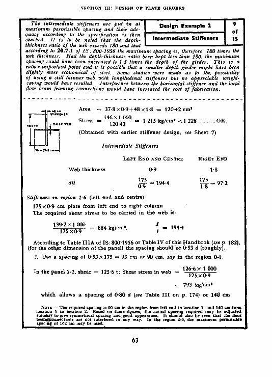
SECTION XII: DESIGN OF PLATE GIRDERS
The intermediate sliffeners are put in at naximum permissible spacing and theiv ade- luacy according lo the specijicaliolr is then heched. It is to be noted lhat the deblh- hickness ratio of the web exceeds 180 and >hat 1 I
wcovding to 20.7.1 of IS: 800-1956 lhe maximum spacing is, therefore. 180 limes the ueb thickness. Had the depth-thickness ratio been. kept less lhan 180, Ihe maximum @acing could have been incveased to 1.5 times the depth of the girder. This is a ,alher imporlani point and it is possible lhal a smaller depth girder might have been Zightly more ecwomical of steel. Some studies were made as to the. possibilily )f using a still thinner web wilh longitudinal diffeners but no appreciable weight- raving would have resulted. Inferference between the korizonlal stiffener and ihe local Poor beam framing connections would have increased the cost of fabrication.
Area = 37.8 x0.9+48 xl.8 = 120.42 cm’
Stress = 146x1 000 = 120.42
1 215 kg/cm’ cl 228 . . . . . OK,
(Obtained with earlier stiffener design, see Sheet 7)
Infermediate SIiffencrs
Web thickness
LEFT END AND CENTRE RIGHT END
0.9 1.8
175 oT = 194.4
175 m = 97.2
Stiffeners rn region 1-6 (left end and centre)
175 x0.9 cm plate from left end to right column The required shear stress to be carried in the web is:
139.2~1 000 175 x 0.9
- = 884 kg/cm*, d - = 194.4 t
According to Table IIIA of IS: 800-1956 or Table IV of this Handbook (we P. 182), (for the other dimension of the panel) the spacing should be 0.53 d (roughly).
:*. Use a spacing of 0.53 x 175 = 93 cm OY 90 cm, say in the region O-l.
4n the panel l-2, shear = 125.6 t; Shear stress in web = 126.6 x 1 000
175 x0.9
- 793 kg/cm’
which allows a spacing of 0.80 d (see Table III on p. 174) or 140 cm
Norr - The required spacing is W cm in the region from left end to location 1, and 140 cm fr@ location 1 to location 2. Based on thue ti@ucs, the actual s acing required may be adjust& su~tahly to give symmetrical spacing and good appearance. 1 It s ould also be seen that he door be~nncctions are not interfered in any nay. rpaciw of 162 em may be used.
In the w&on 2-6, the maximum pumisriblc
63

III IIANDBQOK FOR STRUCTURAL PNGINESRS: STEEL BSAMS AND PLATE GIRDXRS
The required momCnt of inertia of the inbsv- mediate stiffeners is determined. In the present design, almost any reasonable selection of sti’ener will satisfy the moment of-inertia requirement. Although some designers will prefer to use intermediate stiffeners in pairs, this is not absolutely necessary provided adequate support is supplied and the stiffeners are not depended npon to maintain the shaQe of #he cross-section. Some sating in steel weight could be effected here by using stifleners on one side only but My are called for on both sides in this design as representing best &sign practice.
Moment of inertia of stiffeners about centre of feb should %e
1.5 ‘$ (see 20.7.1.1 of IS: 800-1956)
_ la5 x (175)’ x (0.9)’ (90)’
= 725 cm‘
cm
It is a good practice to use the outstanding leg of the stiffener not less than 5 cm plus l/30 the depth of beam and its thickness l/16 the width of the out- standing leg.
1‘. Stiffener width = 5+ ‘2
= llcm
Thickness 11
“ix+
= 0.7 cm
For 11 x O-8 cm, III = 0.8 (22.918
12
= 8OCJcm’>725 . . . . . OK.
Stifferers in tke region 6-7
W - 175 1T
= 97.2
Spacing c = 180--33.84 f 14616 cm
c/d = ‘?!!% 175
= 0.935
Fs = 945 kg/cm* . . . . . OK. Bearing stiffeners eliminate need of intermediate stiffeners in this region.
64

SECTION ISI: DESIGN OF PLATE GIRDERS
The longitudinal transfer of shear stress between web plate and flange plate in &he various
Design Example 2 II
panels along the girder is tabulated and requi- site fillet welds are chosen. If the minimum
Welding of Web & of
size fillet weld permits a continuous weld Flange Plates I5
without excessive loss in economy. such COW-
tinuous welds are desirable. and should be used in any case at the ends of the girder as specified in IS: 800-1956. Reference should be made to 18 (see p. 52 ), -________--__-_-__-_-- _-___--__ ---________ ____-
Welds
From Eq 7:
f = 32 E II ’
f*’ = y
Thus shear per linear cm = tfs = lr, = y; xl 000 kg/cm
PANEL V MAXIMU~I
SHEAR
tonnes
o-1 139.2
1-2 125.6
2-5 112.0
5-6 62.8
6-7 255.2
l Q cm8
9 550
17 385
24 000
17 385
17 385
I cm’
2 097 000
3 310 000
4 776 000
3 310000
3 310000
f” kg/cm’
2 FILLET WELDS
634 16 mm contmuous (2 x430.5 = 861 kg/cm)
656 t9.5 mm x 23 mm @ 32 cm c/c
(922,s x 23 = 663 kg/cm) F2
569 t9.5 mmx22 cm @ 35 cm C/C
(922.5 x 22 = 580 kg/cm] 33
328 t9.5 mmxl0 cm @ 29 cm C/C
1922.5 x 10 = 350 kg/cm: 29
1 334 t9.5 mm continuous (2 x681.5 = 1 363 kg/cm)
Wars -- In joining 34 cm and 5 cm thick plates, 9.5.mm fillet weld is the minimum permissibl acwrding to IS: 818-1056. In 1-2. 2-5 and 6-0. the web plate thickness 1s 0.0 cm. The strengt of web plate m bhear = 0.9 x 915 kg/cm. Since tbls is localized, a maximum of 1025 (see 9.3. of IS. 800-1050) mzy be assumed to give 0.9~ 1 025 = 022.5 kg/cm length of plate. Compare’ to this, the strength of 9.5.mm weld lines on both sides of web plate = 2~0.7~0.95~ 1025 = 1363 h<jcm. Hence, the value 022.5 kg/cm controls.
m-m-ot of dange area about neutral axis. $L?.1 Of is: BM-1956.
65


SECTION III: DESIGN OF PLATE GIRDERS
An alternative tapered flange design is shown in the sketch. Each of the two flange segments may be flame cut on the skew with metal as shown in the sketch. jlange will saue an appreciable amount of steel beca,use of the closer fit of fhe moment capacity along the girder to the actual bendtng moment. The moment capacity is plotted as the line in dashes on Sheet 5. The introduction of the taper involves both advantages and disadvantages which are tabulated as follows:
Advantages
1) Saving in steel.
2) Elimination of two transverse butt welds in each pange.
3) Reduction of stress concentration in the flange.
IXsadvantages
1) Flanges shall be made in pairs by a longitudznal jalne LZC~ (in 67.5 cm wzdfh and 85 cm width plates for the above flange section ).
2) In addition to the cost of Jame culting ( which, however, should be more tha?z offset by the saving in reduced welding) the Pange plates may wavp when they aye split longitudinally owing lo the existence of residual stresses. Thzs would &her require straightening afterward 01 annealing prior to pame cutting.
3) The fitting ufi of the girder would be more di@cult because of the taper.
4) In supporting the girder at point of bearing OY at concentrated load points. the local details may be a bit more complicated because of the tapev.
67

ISI HANDBOOK FOR STRUCTURAL ENGINEERS: STEEL BEAMS AND PLATE GIRDERS
The moment capacity of this 13.5 cm width flange (at left end) is:
M = fI= 15~ClOx*1495 500 __~.__ = 242 m.t Y 92.5 x 100 x 1 000
- ------ --_..
n,
At location 3 : 1500x4776000
M = 92~5~~lt,~~~~~o~ = 775 mt >753.6 (see Sheet 2) . . . . . OK.
At location 4, a capacity of 682.4 ~rnt is required.
The strength at 0.3 m beyond location 4 will be kept at 682.4 mt.
. Required I of section = . . 682~4x92~5xlOOOx1OO = ~2200000cm, -- --~~- 1500
42oOOOf-402000 Required b = __
2 x 5 (88.75)s = 48.2 cm
In 2 m length the reduction in width = 54.0-48.2 = 5.8 cm
In 7.8 m length the reduction in width = i x 7.8 = 27.3 cm = say 27 cm
The available width at the end ii this rate of reduction in width of plate is adopted as 54-27 = 27 cm > 0.25 (54) . OK (requir- ed in IS: 800-1956, see Note under Table XIX of Appendix E). The moment capacity for this flange width (at right end) : ~27~2~5X(90)*+(402000)] 1500
92~5x1OOxlOOO = 420 mt With these values of the moment capacity, the capacity diagram is drawn in Sheet 5. It may be seen that it is adequate. Width at right end to be adopted which is at a distance of 7.99 m from section 3 = 13.5 cm.
CUTTING PLAN
Quantity of two tapered flanges (rect plate required) : 5.0 (67.5 x 6.29 x 100+85 x 8 x 100) = 550000 cm9
The variable thickness flange required
= (2x259~0x2+2x150x3~6+710x2x5+3~09x3~6x2)54
= 617 490 cm%
Thus the tapered beam is lighter by 530 159 kg (66 990 cm*) of flange plate per girder.
_____-__----------- ---- --- --_- ---. _.
*I web = 402ooO
I flange
= 13~5x5x5x2xOO*= 1093500
Total = 14% 500 cm’
68

SECTION III: DESIGN OF PLATE GIRDERS
Weight take off of actual design with break- Lawn of various components: Sliffeenevs and Ither defails were found lo be 35 percent of &he weight of the web plate, comparing with the figure bf 40 percent ( based OM the 17.5 x 0.9 cm web >late only ) that was assumed.
Design Example 2
of Welded 4 Plate G.. ___
Veights Take Off
1) Welded plate givdev (with jZanges of variable thickness)
Flanges 2-54 x 2 @ 0.79 kg/m/cm” for 2.59 m
2-54 x 3.6 @ 0.79 kg/m/cm’ for I.5 m
2-54 x 5 @, 0.79 kg/mjcm* for 7.10 m
2-54 x3.6’@ 0.79 kg/m/cm* for 3.09 m
Web plates I-175 x 0.9 @ a79 kg/m/cm’ for II.79 m
I-175 A 1.0 @ 0.79 kflm/cm’ for 2.49 m
Stiffeners 2-24 x I.8 @ 0.79 for I.75 m
2x2-20x2@&79forl~75m
2 x4-20x I.3 @ 0.79 for 1.75 m
2x7-11 x0.8 @ 0.79 for I.75 m
z.z 430
= 460
= 3 030
= 950 4870 kg
= 1460
= 620 2080 kg
= 119.5
= 221.0
= 288.0
= 170.5
‘1990 kg
Stiffeners 799 - = __ = 0.384 OY 38,4* percent
Web 2 080
2) Welded plate girder (with -tapered jlanges)
Flanges : From Sheet 14. 550 000 (cm”) x0+07 9 (kg/cmJ) = 4 350 kg
3) Total welded girder
Variable thickness flanges: 7 749 kg
Tapered flanges : 7 229 kg
*Estimate of 40 percent was based on 175 x 0.9 cm web plate; on the same basis the proportion 0
stifhner actually required is go=- 0.45 w 45 percent.
69

ISI HANDBOOK FOR STRUCTURAL ENGINEERS: STEEL BEAMS AND PLATE GIRDERS
24. RIVETED PLATE GIRDER
24.1 The riveted plate girder provides a beam that has behind it many decades of successful design experience. Recause of the following factors, the riveted girder will use more steel than its welded counterpart. It shall be designed with reduced stress allowed on the tension side on account of net section. Stiffeners shall be angles instead of plates, and filler plates shall be used under bearing stiffeners.
24.2 The following are weights of the welded girder as designed in Design Example 2 both with conventional variable thickness cover plates and with tapered width flange plates along with riveted plate girder design:
Welded girder, conventional flanges: 7 749 kg Welded girder, tapered width flanges: 7 229 kg Riveted girder ( Design Example 3 ): *9 602 kg
25. DESIGN EXAMPLE OF RIVETED PLATE GIRDER
25.1 The riveted plate girder is designed with exactly the same load condi- tions and general dimensions as the welded plate girder in Design Example 2, in the following 14 sheets ( see Design Example 3 ).
*Could be reduced to 8 525 kg by crimping intermediate stiffeners.
70.

C
,
1
I
SECTION III: DESIGN OF PLATE GIRDERS
Design Example 3 - Riveted Plate Girder
Loading, shear, and moment estimates are repeated from welded girder Design Ex- ample 2. Although the riveted girder uses more steel than its welded counterpart, tke estimated allowance for girder dead weight was somewhat too high zn the welded girder design and the same weight estimate should be satis- factory for the riveted girder design. The over- all depth by Eq 8 (see p. 50) involves a k factor of 5.5 instead of 5,Oas used for the weldedgirder.
m
This is as recommended by Vawter and Clark+. The riveted girder should be some- what deeper than a welded girder for maximum economy because the jlange angles bring the distance betweex the centroids of the jlanges somewhat nearer together than in the welded girder. In addition, the web plate is supported at the edges of the flange angles ond the over-all depth of the girder may, therqfore, be relatively greater without ex- reeding the allowable web deptk-thickness r’atio. It will be noted at the bottom of Sheet I that l/S of the area of the web has been imlirded in the flange area. ----------_--------------~~-----_______________,
Riveted Plate Girder
Loading: ( Same as Design Example 2)
I %.u* 7, The moments and shears from Sheet 2 ( Design Example 2 )
Over-all depth d = 5-S sz J
-r = x100x1000
= 36.8x’S.S = 202 cm
Clear distance between flanges ( assuming 200-cm web depth and 0.5 cm clearance gap and 150 x 200 mm flange angle ) = 200+(2x0.5)-2x115 = 171 cm (see sketch)
Minimum web thickness = 171 = 0.85 cm 200
Use web plate 0.9 x200 cm. If over-all depth is assumed to be 210 and effective
depth 200 cm
Average flange stress 1500x200
= --- = 1 429 210
kg/cm’
Area required 753.6 x 100 x 1000
= 2ooXi.-429P= 264 cm’
Trial section : (l/8) web 200 x 0.9 cm = 225 cm’ 2 angles 150 x 200 x 18 = 59.76 x 2 = 119.5 cm’ Cover plates 55 x 1.25 cm = 68.8 cm’ Cover plates 55 x 1.4 cm = 77.0 cme
Total asea = 287.8 cmp --__-______________--_---~---~~~_~~~-~~---- - - --_
•VA~VTER, J. AND CLARK, J. G. Elementary Theory and Design of Flexural Members, New York. John Wiley and Sons Inc., 1950.
+4.r fnn,nn,e nn n ul
71

ISI HANDBOOK FOR STRUCTURAL ENGINEERS : STEEL BEAMS AND PLATE GIRDERS
The table at the top of the sheet provides a computation of gross moments of inertia for Ihe
Design Example 3 2
plate girder without cover plates, with one of
cover plate, and wilh two cover plates. The Design of Girder I4 moments of inertia without cover plates and with one cove” plate will be needed both for determining cut-off points of the Pange covey plates, and, in addition. to de#ermine rivef pitch. CYOSZ moment of inevlia should also be used in dejection calculation. The static moments of the various jange areas both with and without angles aye labu- lated as these ave needed later to determine rivet pitch. _-_----_-__-_-_-~--------------------~~_________
Calculate gross and net flange areas and gross moment of inertia 0, 1 and 2 cover plates :
Web 200x09 80 - ‘V
600000
Web between angles 14.5 x 0.9 x 2 26.1 1~2.3~09 24.03 AI&S 2O~x1s*ox~8 119.62 l *(4 x 2.3 x 1.8) lo%94 t1a?oo 2 22oboo Angles -
11X52 - ii&0 4X118&9
Flange with zero 4 645
eovsr plate - :(+26) 92x2.3x1.8 (+24) - 2 824 454
1 cOver qlats 65 x 140 y&f
2 x 2.3 x 1.4 70.6 20 500 1 678 600 npcty wth 1 cover 173.64
- (+24) , - 4 40s 045
Scoond plate 56 x 1.25 8876 2x23x1*25 * 21000 1 444 000 “pEfz n1th 2 covet 2:*:4
- y$%: (+24) - 5 847 045
Moment capacity, MO ( see 20.1 in IS: 800-1956 )
MC = $!(A+$)
Flange with 2 cover
plates = Me = 1500x584704.5x2x260+i4 291.27 x 206.3 x 100 x 1 000
= 760 met
One cover
plate = M6 = 1 500 x 4 403 045 x 2 x 197.54 222.52 x 203.8 x 100 x 1 000
=I 575 IIlk
No cover
‘late = Mc = 1500~2824545~2~135~2
145.52~201 x100x1 000 = 395 met
----------__-______________~-~~-----~~~~~~_____ l 2C’-W84) V&, of ISA 200 150, 18 mm ) - 193.32.
‘*The net area calculation is based on 4 rivets, taking tbat they are staggered. td.! _ (193.32):
: z213 is tqkrds the weq$ate between the Bange an les 14.5 x 0.9. OOnly 2 rivet holes ccns~ ered as where there is no f
horizontal Iegs. of angles. ange plats there will not be any rivet in the
72

SECTION III: DESIGN OF PLATE GJRDERS
The bending moment diagram 1s dvawn (data on Sheet 2) and fhe theoretical cut-off poiGts of couev plates are determined at the intersections of the horizontal bending moment capacity lines with the actual bending moment cuvue.
Design Example 3 3 of
Design of Girder 14
____-----------------~~_~~_~~~~--~~~~-~--~~~~~~
Statical Moments of Flalzges ‘Q’
GR&S AREA ARM .STATIC.U MOMENT Q
Angles 119.52 193.3212 11 560 cm*
14-cm plate 77 202412 7 XWJ cm’
Beam with one cover plate - - 19 360 cmf
1.25cm plate 68.75 20505/2 7 050 cma
Beam with two cover plates - - 26 410 cmi
2 plates no angles - - 14 850 cm1
Bending Moment Capacity provided by conventional curtailed flanges (see Sheet 2 ).
73

1SIHANDBOOKFORSTRUCTURALENGINEIRS:STEELBEAMSANDPLATEGIRDERS
The dead weight estimate is checked and it may be pointed that 80 percent of the web weight has been added for stiffeners and other details. This is 10 percent rnovc than the suggested weight allowance ire 15.1 (c) but the additkonal 10 percent is justi$ed because of the two bearing stiffeenevs for columns ZII the znteviov part of the girder. A! the bottom of this Sheet ave tabulated the rivet pitch calculatiorrs based on previously determined values of shear (I’), gyoss momcut of inevtia (I), rivet value (R), and static moment (Q) of the aveas to which the stress is being transferred. The rivet values for the web to angle transfer are all based on web bearing for a .&n&e rivet, axd the rivet values for a*?gle to cover plate are based on two rivets in single shear as these rivets will be zrscd in pairs.
Web plates at vight end:
Maximum shear = 255.2 t
Area required 255.2 x 1 000
945 - = 270 cm*
Use web-plate 200 x 1.4 cm = 280 cm’
Check dead weight estimate:
Web area (0.9~cm thick). = 180 Flange area = 530 (based on 2 cover plates) Stiffeners and other details (80 percent of
web) = 144 854 cmr
Weight per metre = 854 x0.79 = 675 kg/m < 900 kg/m assumed . . . . . OK. Flange to web rivets (power driven shop rivets) Rivet values (R”), allowable loads for 22 mm rivets
Bearing on 0.9-cm web = 2 360x0.9x2.3 = 4885 Bearing on 1.4.cm web = 2360x1.4x2.3 = 7600 Bearing on 2 Ls = 2360x1%x2x2.3 =19 550 Double shear for web rivets
or shear of t\vo rivets -for _ 1 025x2xTCT = 8500 flange rivets >
4
. Bearing on web will control. . . Rivet pitch P = g (Eq 12 on p. 52)
PANEL V Igross (tonnes)
WEB TO ANGLES ANGLESTO FLANGE PLATES
O-1 139.2 2 824 545 l-2 125.6 4 403 045 2-3 112.0 5 847 045 3-4 35.6 5 847 045 4-5 49.2 5 847 045
5-6 62.8 4 403 045
6-7 25‘5.2 4 403 045
’ R Q P’.’ R Q P’
4-885 11 560 8.5 4.885 19 360 8.7 4.885 26 410 9.5 4.885 26 410 JO.3 4.885 26 410 21.9
- 19 360 { 17.7 27.1
7.600 19 360 6.7
8: 7GO 38 8.5 14 850 30 8.5 14850 94 8.5 14 850 68
8.5 7800 76.5
8.5 7800 18.8
74

SECTION III: DESIGN OF PLATE GIRDERS
Sketches indicate vtvet avvangemevts tteav the wads of a COWY plate and in an unfolded deuel-
Design Example 3 5
opmenl of the angle. Mtnimum pttch is . of detevmzned to maintain the net section that was Flange to Web Rivets 14 used as a basis for thr ~%ltge awa requzvement. Speci$cation clausrs for other rivet pitch requivements ave referred to with the yecom- mended pitch tabulated at the bottom of Sheet 5. It zs pwmcssible lo use a greater pitch in the top plate than in the vevtrcal 1rg.s of the angles.
According to 19.2.2 of
* --+------- hole for each staggered line of rivets. Therefore, mini- mum pitch allowable for this connection is that which ts.n-4 adds one rivet hole diameter
-c?- wrn
P’ p=/4g = K73 = 2.3
P = 8.3 cm For a, say 6.25~cm line spac-
ing _-__ P =42.3x4x6.25
= 7.57 cm
Straight line pitch for staggered rivets on same line in angles-Maximum 24 1 or 300 mm ( we 25.2.2.3 of IS: 800-1956 ).
TRIAL PITCH ANGLES TOP PLATE REMARK
PANEL STAGGERED PITCH, cm. STAGGERED PITCH*, cm (1) (2) (3) (4) o-1 8.5 No plate l-2 8.5 15 At ends of cover 2-3 plates reduce to 3-4 6.0 cm pitch. 4-5 15.0 15 S-6 15.0 15 6-7 6.7t 15:
---___-__~___L----_---~--~-~~~--- *For convenience of riveting, shop may prefer same pitch as in 150-mm leg ( as in co1 2 above). tWith VI-cm staggered pitch, net area in panel 6-7 is given by deducting from the figure to be
obtained in Table in Sheet 2 for net area of Banae with 1 cover plate L 173.32+24 ).
A value corresponding to P’/4g = $&= 1.79 cm
:. Revised net area assuming that same pitch of 6.7 cm for flange and web - 197.32 - 1.79 (1%)2 - 1.79 (1,4)2 = 185.85 cm*
1500~4403045~2x185+35 MR = 7ty3.52 x 2m.8 xiy$jjl-m = 549 m.t
Actual Moment in 6-7 is 458.4. Hence, && x 100 = 176 percent more . . . . . . OK.
For pahe 6-7 according to Sheet 4, a line pitch of &?.6 cm is required. pitch of 9.4 cm it is ahight.
If we have a staggered
Ierr ir recommended. But for shop convenience same pitch as in O-l, l-2, etc. for the 150 mm
75

IS1 HANDBOOK FOR STRUCTURAL ENGINEERS : STEEL BEAMS AND PLATE GIRDERS
On this sheet, the’ arrangement of *iv& at the covev plate cut-off points is itidkated and various code stipulations are vejerved to and explained.
Allowable pitch per line of rivet,s (see 25.2.2.3 of IS: 800-1956) = 24 x 1.25 =30 cm * Use a staggered pitch of 15 cm. . .
Adopt same pitch for both compression and tension flanges for economy in fabri- cation.
Actual cut-off points For I.4-cm plate: (see 20.5.1 of IS: 800-lb56)
The net area of the plate with the above pitch = 70.5 cm’ (see Sheet 2) Strength of the plate = 70.5 x 1 500 = 106*00 t Shear value of rivet controls and is equal to 8*5/2 = 4.25 t (see Sheet 4)
No. of rivets required to develop the strength of plate = g = say 26 rivets
Half the number of these rivets (13) are required in the extension of cover plate beyond the theoretical point of cut off.
The minimum staggered pitch being that which adds one rivet hole diameter = 8.3 cm (see Sheet 5).
Adopting &S-cm pitch as required in the angles to web connections (sse Sheet 5) and with two staggered lines of rivets, one on each side of web, the extension length required to carry 6 rivets is .about 6 spaces plus the minimum edge distance = 29 mm (see Table XII in 25.4 of IS: 800-1956).
The edge distance of cover plate in the transverse ! direction = 55-_(11’9+15)
= 14.05 cEl
As this is a single plate at this point of cut-off and the plate girder is not in an exposed condi- tion, the maximum edge distance permissible is 16 t = 16x 1.4 = 22.4 > 14.05 OK (see 18.4.1 and 25.4.i.i’ of IS: 800- 1956).
For 1.25-cm plate, the net area as before = 63 cma (see Sheet 2) Its strength = 63 x 1 500 = 94.5 t A 22-mm diameter rivet has a shear value of 425 t (see Sheet 4).
94.5 No. of rivets required = 4.25 - = 22 rivets = say 26 rivets
Same extension and spacing of rivets as for the 1.4cm thick cover plate may be adopted at both ends of cut-off of this cover plate.
Check the edge distance. The plate girder not being in an exposed situation, the minimum permissible edge
distance is 12 t or 15 cm whichever is small, 12 t = 12 x 1.25 = 15 cm > 14.0 cm adopted . . . . OK (see 25.4.1 of IS: 800-1956).
26

SECTION III: DESIGN ‘OF PLATE GIRDERS
These sheets all concern the design of bearing sti$sners at supports and under column load locations. As in the case of the welded girder, the bearing stiffeeners at the columns are pu# in double pairs so as to pick up the column flange load and eliminate bending stress in the cover plates and top angles. At the left end, where bearing is on a masonry wall, four angles are also used but these are turned together instead of apart so as to localize the load eve? the centre of the masonry wall. explained on the design sheets.
The design of bearing stiffeners is fully
--------____---_-...-_--._____-------____-~-~-----
Bearing Stiffeners Under Right Column (Load 179 t ) Allowable bearing stress = 1 890 kg/cm*
Required contact area = 179x1000
1 890 = 95 cm1
Allowing 1.5 cm for the root fillet of flange angle, if 200x 100 angles are to be used, total thickness required
95 95
=2oo--15 =185 = 5.15 cm [see 20.7.2.2(b) of
IS: 800-19561 Adopt 4 ISA 200 100, 15 mm which gives an area of contact:
4(20.0-1.5) 1.5 = 111 cm2 > 95 cm9 required .‘. . OK. With 22-mm rivets, R for bearing on web = 4.885 t and controls (see Sheet 4)
NO. of rivets for filler plates
179 =4x85= 36.64, OY say 36
For angles double shear controls and No. of rivets on Angles
179 8.5
= 21.06, or say 22
Being under compression, maxi- mum pitch = 16 x 1.5 = 240 (see 25.2.2.1 of IS: 800-1956)
Use 2 rows of 12 rivets in angles and one row of the same number in the filler as shown in the sketch on the left.
Check for strut action:
Effective length of web = 0.9 x 20 = 18.0 cm [spe 20.7.2.2(a) of IS: 800-19561 1 = 2 x 1.5 x @4.5)*x l/12 = 22 000 cm’ (see sketch below)
1 due to other parts is very small.
Area = 4x42.78 = 171.12 cm*
Web = 0.9~71 = 63-9 cma 23502 cm0
_---__--_--__-__-___~_-___--~-------- :_____--_ *The column section supported by the girder at this section is ISHB 350. Hence, the bear&
stifiners are also kept at 35 cm apart to be against the flange of the column section.
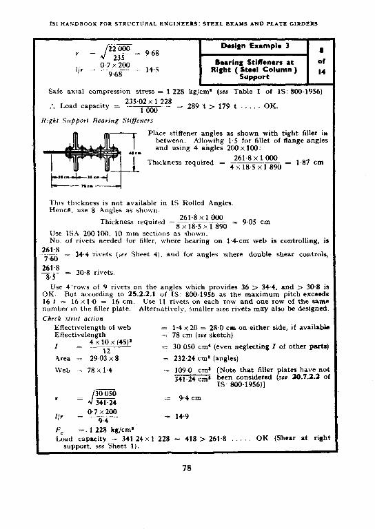
ISI HANDBOOK FOR STRUCTURAL ENGINEERS: STEEL BEAMS AND PLATE GIRDERS
Safe axial compression stress = 1 228 kg/cm’ (sea Table I of IS: 800-1956)
235.02 x 1 228 * Load capacity = . . loo0 = 289 t > 179 t . . . . . OK.
Place stiffener angles as shown with tight filler in between. A-llowihg 1.5 for fillet of flange angles and using 4 angles 200 x 100:
261.8 x 1 000 Thickness required = K,mi8W = 1.87 cm
This thickness is not available in IS Rolled Angles. Hence, use 8 .4nEles as shown.
261.8 x 1 000 Thickness required =8x185xi890 = 9.05 cm
Use ISA 200 100, 10 mm sections as shown. No. of rivets needed for filler, where bearing on 1.4~cm web is controlling, is
261.8 --- = 34.4 rivets (see Sheet 4), and for angles where double shear controls, 7.60 261.8 ___ = 30.8 rivets
8.5
Use 4’rows of 9 rivets on the angles which provides 36 > 34.4. and > 30.8 is OK. But according to 25.2.2.1 of IS: 800-1956 as the maximum pitch exceeds 16 t = 16 x 1.0 = 16 cm. Use 11 rivets on each row and one row of the same number in the filler plate. Alternatively, smaller size rivets may also be designed.
Check strut action
EffectIvelength of web EffectIvelength
I 4 x 10 x (45)’ = __-__
12
= 1.4 x 20 = 28.0 cm on neither side, if availabk =: 78 cm (see sketch)
= 30 050 cm* (even neglecting 2 of other parts)
Area = 29.03 x8 = 232.24 cm* (angles)
Web = 78 x 1.4 = 109.0 cm’ [Note that filler plates have not 341.24 cms been considered (se@ 20.7.2.2 of
IS: 800-1956)]
I - 9.4 cm
0.7 % 200 r/v = ___ 94
= 14.9
Fc =. 1 228 kg/cm’
Load capacity = 341.24 x 1 228 = 418 > 261.8 OK (Shear at right support. see Sheet 1).
78

SECTION III: DESIGN OF PLATE GIRDERS
iTsing 4 Angles, 200 x 100 mm:
Phickness required = 146x1 000
4(20- 1.35) x 1 890 = 10.4
Use 4 ISA 200 100, 12 mm sections.
Design 3 Example 9
Bearing Stiffeners at of Left -( C;;;;wz Wall ) ~14
-I- 204 cm
c PILLLR PLATE EXTENSION
0.Vcm
-3.
-I-
F, = 1 228 kg/cm*
Load capacity = 170.76 x 1 228 = 209 > 146. . .
Bearing slifleners under left column (load = 134 t ) Use 4 ISA 200 100, 12-mm sections.
Design is -similar to that at right column load. -----__--_------_--_--__________
*Left SUmoTt shear. II.3 Sheet’1.
Number of rivets:
For filler = 4.885 146 = 29.6
For angles =lG = 17.2
Use 4 rows of 10 rivets as shown with a pitch of 18 cm c/c. This would provide 40 rivets for filler plates and 20 rivets for the stiffener.
Check strut action :
Effective length of web
= 2(20x0.9)
= 36 cm
I = 2x1.2x(44.5)* 12
= 176OOcm’
-4 =4x34.59+36x09 = 170.76 cm*
17 600 I = J- 170.76
= 10.15 cm
0.7 x 200 I/r = ____
10.15
= 13.8
. . OK.
__--__----_____
79

IS1 BANDBOOK FOR STRUCTURAL ENGINEERS: STRRL BEAMS AND PLATE GIRDERS
At the intersection of the 1*4-cm and 0.9-cm uebs a splice shalt be introduced to transfer he total bending moment and shear allotted to he web at this section. 1.5 m to the left of panel point 6 where the ieavy column load causes a great.increase in shear to the right end and creates the reed for the 1.4~cm web plate. The @ice plaies are effective i,n moment in proportion o the square of their depth and, therefore. the total required cross-sectional area is determined by multiplying the web area by the square of the ratio of web height to splice plate height. Since the rivets are assumed to be stressed in proportion to the iistance from the net&al axis, the maximum allowable horizontal component of rivet rtress is reduced accordingly.
For an exact fit of the splice plate, 0.25cm fillers would be needed on each side of !he @9-cm web to mahe it match with the 1*4-cm web to which it is spliced. The value in bearing on the 1.4-cm plate is considerably greater than for the 0.9-cm plate and, Fherefore, only two rows of rivets are ,required on the right side of the splice. The rivet pattern as shown for the left side rs arrived at after several rouglr trials. __-__-___-___-__-__________________________________~-.
Web Splice
Splice to the left of the bearing stiffeners under the right column (0.5 m from panel point 6)
Shear at spliced section = 62.8 t; Moment at spliced section -= 489.8 m.t R 22 mm diameter rivet on O-9-cm plate web = 4.885 (see Sheet 4)
l , ,I I, ,B on 1.4-cm web = 7.600
Total area of splice plates required = A. 0
f 0
= 249 cm’ s
~~70~eight of splice plate being 200-2 x 15
Total thickness required = To = 1.46 cm
Use 2 plates (preferred dimensions for plates: 170 x 0.8 cm)
Maximum allowable value for horizontal stress in the splice plate rivets
= 4.885 x (distance between extreme outside lines of rivets on splice plates) (distance between extreme lines of rivets flange angles to web)
= 4.885 x 171~-‘(4.0)2 201-(55)2 = 4*28 *
Assume the adjacent pattern of rivets.
Width of splice plates
Edge distance = 3.8 cm for 22-mm rivets, adopt 4 cm on either side; pitch = 3d = 3 x 2.3 = 6.9 or say 7 cm.
80

SRCtION .11X: DRSIGPJ O? ?LATR GIRDRRS
The rivet jutttcru for the iefi side of the s#ce is s&mn. This patterm was awiued at after sevcrai rough trials.
Pitch at splice point should be slightly more as the minimum edge distance required for the web plates being spliced should also be satisfied. Taking these edges as sheared, Table XII of IS: 800-1956 requires 3.8 or say 4.0 cm minimum edge distance for 22 rivets. in the sketch.
Hence, adopt 8-cm pitch in the middle portion shown
( See Elevation in sketch on Sheet 10 )
Thus, the total width of splice plate = 37 cm
2 x (10.2)’
3X(20.4)’
2 x (30.6)’
3 x (40-8)’
2 x (51)’
3 x (61.2)’
2 x (71.4)’
3 x (81-S)’
208
= 1248
= 1872
= 4994
= 5200
= 11250
b 10200
3 19950 __ -_- 54 922 ems
~‘-2~34922 = 109 844
.&=*26x (7)’ = 1 274
111118
_____________--_____-_--_- ___-________-_____-_ *The mtre Of gravity of the rivet @vu~ on the O%can thiak web side ma, be appmimately taken
tobsattbe~eofthetbreernetrontbemntlslhre(tua~tch).
h~~~$m*tk
ToWnumber ofrlvetsoniefl . Tot.dnmnberofriwtsonri&textnwliwcf tbsgoup i. 17 Tot& rivets - 86
middle tine have no moment, the &tame bet- c~tre of &ity and the rivei

IS1 HANDBOOK FOR STRUCTURAL ENGINEERS: STEEL BEAMS AND PLATE GIRDERS
One-eighth of the web area may be assumed as equivalent flange area in a n’veted girder. Both the maximum horizontal component of rivet stress and the total resultant stress of the most stressed rivet are found to be within satisfactory limits. The intermediate stiffeners required 1,8-cm filler plates which add corsiderably to the weight of the givder. This use of
filler plate is optional for intermediate stiffeners and depends on whether or not the fabricating shop has crimping equi$ment that will permit theiv elimination. .-----__-_-____________________ __,____________---
Au/8 Moment of web to be resisted by splice = --
Au/8+AF x Moment at splice point
(AF is net area of flange )
= 8 x (2002$~~~;l,3.54) x 489.8 = 56.2 me’
* 56.2 x 80 x 100 ?!I=
111118 = 4.05 t < 4.22 t (see Sheet 10) . . . . OK.
*” -= 62.8t 62.8
(17+17+9) rivets =- = 146t
43
* = ~/rm’+rv’ = v’(4~2)‘+(146)’ = 4.35 t < 4885 t (rivet value). . . . . OK.
Use 3 rows of rivets, left side of splice spaced at 10 cm c/c vertically as shown in Sheet 10. On right side, the rivet value, R = 7.60
4885 Number of rivets required = -7~ x 43 = 27.8
* use of 34 rivets as shown at Sheet 10 is OK. Pack&g is less than 6 mm and no excess rivets required . . . . . OK (see 24.6.10 of IS : 800-1956)
Intermediate Stiffeners 177.53
In region O-6: Thickness of web = 0.9 - = 2.09 E.??
= 0.888 ti (see 20.6.1 %S: 800-1956) * . . vertical intermediate stiffeners are required. Use pairs of angles100 x 75 X 6 mm.
I es = 0.6x (24.5)*/12 = 735 cm* Required Ikin, = 1.5 data/C* (see 20.7.1.2 of IS: 800-1956)
Il.5 (171)’ (0.9)s Assuming c = 150 cm, Imin +--
(150)’ . = 243 ems < 735 available.. . OK.
Max spacing allowable = 180 x0.9 = 162 (see 20.7.1.1 of IS: 800-1956) d/t = 171/0.9 = 190, c/d = 150/171 = 0.88
From Table III of IS: 800-1956, fe = 775 kg/cm* V = 775 x200x0.9 = 140 t > 139.2 . . . . . OK (shear in panel O-l)
Assumed spacing is OK. NOTE - If shop has crimping equipment, fillers may be omitted and the stiffeners may be CrimPed.
_____________________---_---------------------- *It may be noted that 0.9.c.m thick web plate has been considered for the calculations here, and not
the 1.4-cm web. This is because l/8 of the area of the O+cm web was the basis in ativinE at the girdel sections ( se Sheet 1).
tShear in panel 6-7. *The heigt of web between closest rows of rivets = 201-2(56+&25) = 177.5 Cm
82

SECTION III: DESIGN OF PLATE GIRDERS
After further calculations in continuation of !he last sheet, the weights take off of the riveted plate girder is given on this sheet and the esti- mated percentages used for details are approxi- mately confirmed.
Design Example 3
Weights Take Off
13 of I4
--------__--_-______--__-----_------__-_ -_--_-_
In region 6-7: c = 180-35 = 145 cm < 180x1.4
T I’Ol.
I d/t = IF4 = 122, c/d = ;$ = 0.85
From Table III on page 174, -f. = 938 kg/cm’ ti = 938 x 200 x 1.4 = 262.6 t > 255.2 t
. . . . . OK ( Shear in panel 6-7 ) * . . Rearing stiffeners eliminate need for inter-
mediate stiffeners in this region. Max spacing of rivets in
intermediate stiffener allowed 1 ;ltc; 16x0.6
:. Use 9 cm.
Weights (in kg) take ofi (based on Sheet 14).
Flanges
2 Plates - 55 x 140 8 0.785 kg/m/cm* for Il.725 m = 1420 2 Plates - 55 x 1.25 @ 0.785 kg/m/cmP for 6.7 m 4 Angles - 200 x 150 x 18 @ 46.9 kg/m for 14.35 m z 2:;;
4840 Web
1 Plate - 200x0.9 @ 0785 kg/m/cm’ for II.725 m = 1670 1 Plate - 200 x I.4 @ 0.785 kg/m/cm* for 2.62 m = 570
2240 Stifjenevs
Intermediate stiffeners - 6 x 2 - 100 x 7.5 x 6 mm Ls @ 8 kg/m 2.01 m = 193
Left support 4 of 200 x 100 x 12 Ls at 27.2 kg/m for 2.01 m = 220 Right support 8 of 200 x 100 xl0 m at 22.8 kg/m for 2.01 m = 366 Right column 4 Ls of 200 x 100 x 15 @ 39.4 kg/m for 2.01 m = 316 Left column 4 Ls of 200 x 100 x 12 @ 27.2 kg/m for 2.01 m = 220
1315 Fillevs for Stiffeners
Intermediate Pls - 6 x 2 of 100 x I.8 for I.71 m at 0.785 kg/m/cm2 = 292 Left support Pls - 2 of 36 x 1.g for 1.71 m at 0,785 kg/m/cm* = 175 Right support Pls- 2 of 55 x I.8 for I.71 m at 0.785 kg/m/cm* = 268 Right column Left column > - 2 x 2 of 35 x 1.8 for I.71 m at 0.785 kg/m/cm2 = 342
i-577 Splrce Plate
( 2 of 37 x I.6 for 1.71 m at 0,785 kg/m/cm9 = 160
Stiffeners and fillers 1 315+ 1 077 = 2 392 kg for 2 240 of web or 107 kg percent of the web assumed on Sheet 4 as 80 percent of 200x0.9 cm web. Actual is about 110 percent.)
I No revision of loadine is necessarv on this account I see Sheet 4 I.1
83

The side view of the plate girder is shown with more than an adequate amount of detail arrangement so as to provide the draftsman su@cient information to make the final detail drhwing.
L- t..! -i*,.,*mj”.‘)..,.o, *Staggered pitch of angles to web rivets.
No?& - For angles to plates, rivets space at 15.cm staggered (except at ends where use M-cm pitch ). Use 22-mm rivets ( power-driven ) countersunk at bearing areas.

NUMERICAL
26. GENERAL
SECTION IV
ANALYSIS OF BENDING MOMENTS AND DEFLECTIONS IN BEAMS
26.1 Although shears, bending moments and deflections may be found for all of the usual cases by means of the tabulated equations in Appendix B, attention will here be given to more generally applicable methods for finding shears, moments, and deflections as required ( for deflection ) when the moment of inertia is variable and/or the loading conditions are complex.
A number of examples of calculations of shear and moment diagrams has already been given in the illustrated Design Examples 2 and 3. However, the subject will be included in this item as a preliminary to a numerical method previously developed by Newmark*. The Newmark proce- dure has special advantages for complex cases and will be extended later to the study of deflections in beams and to columns in Handbook for Design of Columns in Steel.
To the reader not already familiar with the Newmark procedure, it will at first seem unnecessarily complex when used in the computation of ordinary simple beam shear and bending moment diagrams. Such a conclusion would be correct if this were the only application. The great value of the procedure lies in its adoptability to many other problems, most of which it is not possible to cover in this manual, but which include column buckling, beam vibration, etc.
27. NEWMARK’S NUMERICAL PROCEDURE
27.1 In Newmark’s numerical procedure, the beam is divided up into a number of equal length segments and the shear and moment are calculated at the segment juncture points. The use of equal length segments is essen- tial to the full utility of the procedure. A distributed load is replaced by a series of equivalent concentrated loads acting at the juncture points between successive segments.
For example, if the length of each segment is ,I, Fig. 6 and the following will illustrate simple cases relating distributed load to equivalent concentrated load.
*Newmark, N. M. Numerical Procedure for Computing Deflections, Moments, and Buckling Loads. Trans AXE, Vol 108, p. 1161-1234 (1943).

~HANDBOOK FORSTRUCIURALENGINEER~:STEEL BEAMS ANDPLATEGIRDERS
UNIFORM LOa& q PER MLTRE’ RUN
EQUIVALENT CONCENTRATED LOADS
CASE 6) UNIFORM LCMD,q PER METRE
+&I,+,;, 3(++4q2+%) %(q2+%+q$ $(9p14+Q $(q4+2qs)
I I I CASE (6) LINEAR VARIATION IN EACH SEGMENT
CASE(c) PARABOLIC VARIATION IN EACt4 SEGMENT
FIG. 6 EQUIVALENT CONCENTRATED LOADS REPLACING A DISTRIBUTED LOAD
86

SRCTIUN I”: NUMERICAL ANALYSIS OF BENDIIkG MOMENTS AND DEFLECTIONS IN BEAMS
The equivalent concentrated loads are the same as the panel point loads that would be caused by the reactions to a series of simple beams, each having a length X. In Case _(c) of Fig. 6, the load distribution is assumed to be a second degree parabola for two successive segments. At location (l), the segments run from 1 to 3, the same as at location (2).
In a more general way, the equivalent concentrated loads may be written in terms of any 3 successive locations. Let Qba be the end reaction of simple span A-B at B, Qac the end reaction of simple span B-C at B, then the equivalent concentrated ( panel point ) load at B, denoted as Qb, is the sum of Qb,, f Qbc. 3 successive locations :
Thus, summarizing, for any
Case 1 ( see Fig. 7 ): q,,, qb, and qc ‘represent q with linear variation assumed over each length subdivision r\ .
FIG. 7 DIAGRAM FOR CALCULATION OF FORMULB FOR EQUIVALBNT CONCENTRATED LOADS
Case 2 ( see Fig. 7 ) : qb and q. represent q with parabolic variation assumed over length 2\ between A and C.
Qd = $ (35q, + 3q,-05q,) . . . . . . ’ (16)
Qb,, = $ (l.!$a + 5q,---os5q,) . . . . a . . (17)

ISI HANDBOOK FOR STRUCTURAL ENGINEERS : STEEL BEAMS AND PLATE GIRDERS
Qbc =$ (1% + %, - 0.5q.)
Qb = Qa. + Qbc = G- (q. + ‘w,, + qC) . - . - . (19)
In Case 1 applications, if there is a sudden discontinuity in q at any point B, Qi, may be calculated by using average values of qb. Sudden discontinuities in Case 2 applications should be handled by calculating Qbs and Qsc separately, then adding to get Qb. The same procedure should be used in cases where there is a transition between Case 1 and Case 2 at point B.
27.2 The equivalent load system is statically equivalent to the distributed load system and the following example will illustrate the calculation of shear and moment diagrams by the usual procedure as well as by the use of equi- valent concentrated loads. It is again emphasized that the usual procedures are quite adequate in the calculation of shear and moment diagrams and the numerical method is introduced at this point as a matter of expediency in preparation for more useful applications later on.
27.3 A simple problem will be treated initially and it will be seen that the numerical procedure appears cumbersome and of no advantage in such a simple case. The value of the procedure lies in the fact that it handles very complex and special problems of beam deflections with a facility and ac- curacy that cannot be matched by other methods. treated initially by conventional procedures.
The examples will be
Example 1:
Determine the shear and bending moment in a simply support- ed span of 8 metres under a uniform load of 6 tonnes per metre and a concentrated load of 10 tonnes at 2.5 metres from the left support.
Solution A - Shear Area Method (see Fig. 8)
101
1 / b tlm
1 I + 4
ja- l .om .-q
*.r30...t n,r17.11t
FIG. 8 LOAD DIAGRAM
R =6++1O&o= A 30.88 t . . . . . . . . .
R = 58 - 30.88 = 27.12 t . . . . . . . . . (21)
88

SECTION IV: NUMERICAL ANALYSIS OF BENDING MOMENTS AND DEFLECTIONSINBEAYS
The shear diagram (see Fig. 9) is now determined. Immediately to the right of the left reaction, the shear is equal in magnitude to the reaction. For each segment of beam traversed to the right, the shear changes by the area under the load intensity diagram.
x
. . . . . . . . . (22)
-n.t?a
FIG. 9 SHEAR DUGRAN
By starting at the left end (A) and plotting the shear diagram from A to B, a check is obtained on the calculation since the shear at the right end is equal in magnitude to the right end reaction Rs which was previously calculated by independent computation.
For each segment of beam traversed to the right, the moment changes by the area of the shear diagram:
(Mx - MA)= ;Vdx . . . . . . . . . . . . (23)
‘A The moment is zero at A ( hmged end support ) ( see Fig. 10 )
and by calculating the moments at various points, progressively, from A to B, an automatic check is obtained at B where the moment is again 0.
FIG. 10 BENDING MOMENT DIAGRAM
The location of maximum moment is easily determined as the point of zero shear, 348 m from the left end of the beam.
89

151 HANDBOOK FOR STRUCTURAL ENGINEERS : STEEL BEAMS AND PLATE GIRDERS
Solution B - Newmark’s numerical Procedure ( see Fig. 11 )
Newmark’s numerical procedure will be illustrated (see Fig. 11) by dividing the beam into 4 segments, each 2 m in length, with segment or panel points labelled 1, 2, and 3. The reaction RA = 30.88 t is calculated as before, and the equivalent concentrated loads are cal- culated separately for the uniform load of 6 t/m and the localized load of 10 tonnes. For the uniform load ( see Fig. 6 ), each concen- trated load is 2 x 6 = 12 tonnes. The additional load at panel point (1) is the end reaction caused by 10 tonnes acting 10-S m from the end of the first 2 m simple span, which is equal to 7.5 tonnes. Thus, at panel point (l), the total concentrated load is 12 + 7.5 = 19.5 tonnes. Similarly, at panel point (2). the concentrated load is l2 + 2.5 = 14.5 tonnes.
Since all of the loads have been replaced by a series of uniformly spaced concentrated loads, the shear is constant within each segment having length h = 2 m. The concentrated loads are listed in line (a) in Fig. 11, and are given a minus sign. ( In the application of the numerical procedure, upward loads are positive’ since they would cause an increase in positive shear in proceeding from left to right.)
Shear is calculated in line (c) in Fig. 11. Starting with the end reaction RA = 30.88 tonnes, the shear in the first panel is 30.88 - 6 = 24.88 t. The shear in successive panels is formed by successive additions of the negative concentrated loads.
Since the shear is constant in each segment, the change in moment between successive panel points equals VA. Thus, at panel point (1)) the moment ( initially zero ) is 24.88 x 2 = 49.76 tonnes. However, a repetition of the simple additive process so convenient in getting the shear is desirable for moments, so 2 m in this case is introduced as a multiplier in the column so captioned at the right. The use of a common ‘multiplier is made possible by reason of the uniform panel length A used throughout the span. Now the moments are successive simple additions of the shears within successive panel segments. Finally, in line (e), the actual moments at the quarter and midpoints are obtained by multiplying each number in line (d) by 2.
Example 2:
The following example presents a more complex loading case and includes a cantilever extension of the simple beam to the right of the support at B. Reactions, shear, and moment diagrams are presented without detailed computations, followed by the numerical
90

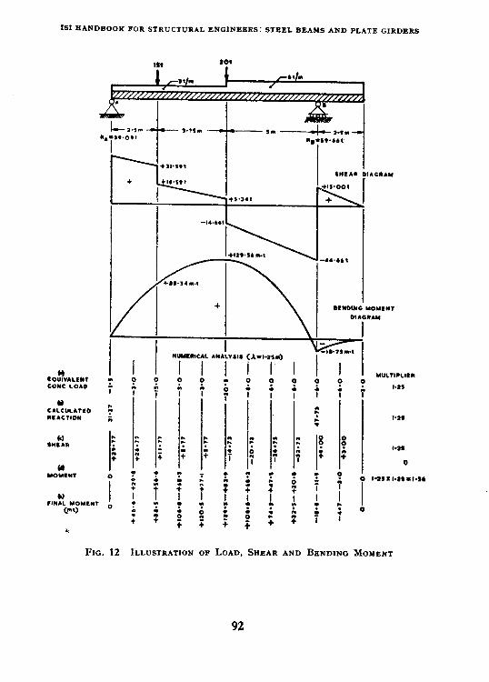
ISIHANDBOOKFORS~RUCTURALENC~NEBRS:STEELBEAMSAND PLATEGIRDERS
COt?“ALEW COYC LOAO
bl CALCULA?CO llACTlOll
0 sntra
(d YOMWT
@I I l1ll.L YOYLWT o
Cm0
FIG. 12
0 5
:: . i
0 :
T : + ILLUSTRATION OF LOAD, SHEAR AND BENDING MOMENT
92
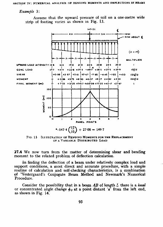
sgcTI_o~-I": NIJMERICAL ANALYSIS OF BENDIN'G MOMENTS AND DEFLECTIONSINBBAYS
Example 3:
Assume that the upward pressure of soil on a one-metre wide strip of footing varies as shown in Fig. 13.
MULTIPLIER
UPWARD LOAD ,NTENSlTV I>C 16.6 19’0 a-0 22-6 23-S 15.0 I
CONC LOAD
SMEAR
MOMENT
FINAL MOMENT (nu)
0 I 2 3 4 5 5 7 PANEL POINTS
‘-147.4 0
$ + 27.08 = 149.7
FIG. 13 ILLUSTRATION OFBBNDINGMOMPNTSPORTHERIZPLACBYENT OFAVAPIABLB DISTRIBUTED LOAD
27.4 We now turn from the matter of determining shear and bending moment to the related problem of deflection calculation.
In finding the deflection of a beam under relatively complex load and support conditions, a most direct and accurate procedure, with a simple routine of calculation and self-checking characteristics, is a combination of ‘Vestergaard’s Conjugate Beam Method and Newmark’s Numerical Procedure.
Consider the possibility that in a beam AB of length L there is a local or concentrated angle.change #o dt a point distant ‘a’ from the left end, as shown in Fig. 14.
93

I~IHANDBOOKFORSPRUCTURALBNCIN~ER~: SIPELI~EAMS AND PLATE GIRDERS
FIG. 14 CALCULATION OF DEFLECTION BY COMBINATION OF WESTBRGAARD'S CONJUGATE BEAM METHOD AND NEWMARK's PROCEDURE
The deflection Y, = 8A.a = BE-~ ................ (25)
Thus eg = 0x; ................ (26)
and, 3ince 40 = BA + 63
’ eA==#ok and eS=+og . . . . . . . . . . . . . . . . . . (27)
Finally, the deflection
. . . . . . . . . . . . . . . . (28)
Now, in place of the geometrical configuration of Fig. 14 consider the result of thinking of the concentrated angle change &I as a load acting 9” a fictitious or ’ conjugate ’ beam having the same length L as the beam in Fig. 14, with resulting shear and moment diagrams as shown in Fig. 15.
FIG. 15 LOAD, SHEAR AND BENDING MOMENT DIAGRAM FOR CONJUGATE BRIM
94
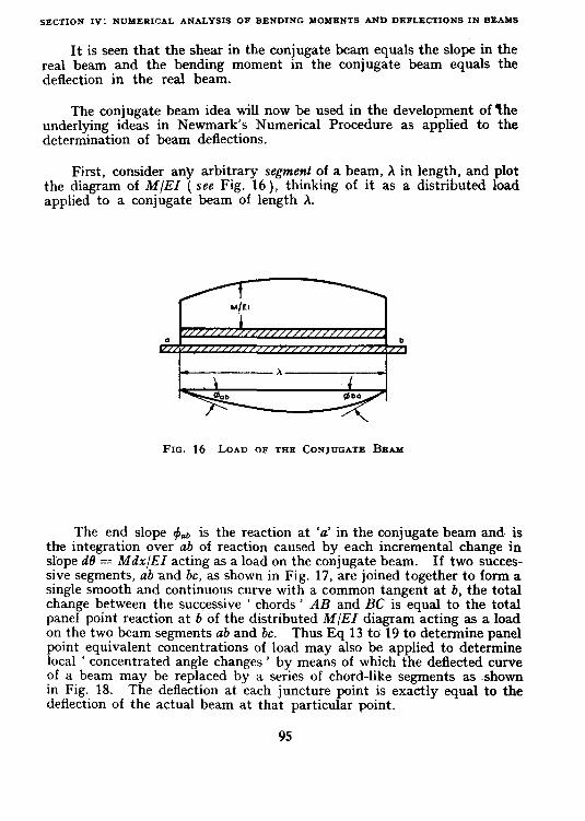
SECTION IV: NUMERICAL ANALYSIS OF BENDING MOMENTS AND DRFLBCTIONSIN BEAMS
It is seen that the shear in the conjugate beam equals the slope in the real beam and the bending moment in the conjugate beam equals the deflection in the real beam.
The conjugate beam idea will now be used in the development of the underlying ideas in Newmark’s Numerical Procedure as applied to the determination of beam ~deflections.
First, consider any arbitrary segment of a beam, X in length, and plot the diagram of MIEI ( see Fig. 16 ), thinking of it as a distributed load applied to a conjugate beam of length A.
FIG. 16 LOAD OF THE CONJUGATE BEAM
The end slope +clb is the reaction at ‘a’ in the conjugate beam and is the integration over ab of reaction caused by each incremental change in slope d0 == Mdx/EI acting as a load on the conjugate beam. If two succes- sive segments, ab and bc, as shown in Fig. 17, are joined together to form a single smooth and continuous curve with a common tangent at b, the total change between the successive ’ chords ’ AB and BC is equal to the total panel point reaction at 6 of the distributed M/EI diagram acting as a load on the two beam segments ab and be. Thus Eq 13 to 19 to determine panel point equivalent concentrations of load may also be applied to determine local ‘ concentrated angle changes ’ by means of which the deflected curve of a beam may be replaced by a series of chord-like segments as ~shown in Fig. 18. The deflection at each juncture point is exactly equal to the deflection of the actual beam at that particular point.
95

181 XANDBOOK FOR STRUCTURAL ENGINEERS: STEEL BBAMS AND PLATB GIRDERS
FIG. 17 CONJUGATE BEAM SEGNBNTS
The conjugate beam relationships establish that the procedure pre- viously demonstrated for determining shears and moments may be used to determine slopes and deflections. A geometrical demonstration of the procedure may be helpful. The average end slope 0,, may be determined -as the average shear in panel O-1 caused by the concentrated angle changes A, +* and & acting as loads on the conjugate beam. The shear in panel l-2 is less than that in panel O-l by +I - it is seen in Fig. 18 that 8,, is less than 0,, by dr. The deflection yr is equal to 0,,,h, yI = yI + &I and so on across the beam-the same quantities are moments in the conjugate beam. As an introductory example, consider the case of the simple beam under uniform load.
FIG. 18 SLOPES AND DEFLECTIONS OF CONJUGATE BEAM
%

SECflON IV: NUMERICAl, ANALYSlS OF BENDING MOMENTS AND DEFLECTIONS IN BEAMS
Exampk 4:
Determine deflections in a uniformly loaded beam ( see Fig. 19 ).
FIG. 19 DEFLECTION IN A UNIFORMLY LOADED BEAM
In line (~2) of Fig. 19, the centre moment is qL2/8 but qL2]32 is introduced as a multiplier to provide convenient whole numbers for the arithmetic procedure that follows. The concentrated 4 loads by Eq 16 to 19 are ‘ exact ’ since the moment diagram is a parabola. The loads are negative since downward load causes a negative change in shear when proceeding from left to right. The multiplier h/12 out of Eq 16 to 19 is coupled with the multiplier in line (a) of Fig. 19. In line (c) of Fig. 19, it is not necessary to compute the slope in the first panel by determining the end shear. &cause of symmetry, one knows that the slopes on either side of the centrc line ( shears in the conjugate beam ) are equal in magnitude and op- posite in sign. Thus, one may start with the concentrated angle change of 46 units at the centre and work to the right and left so as to provide symmetry in the slopes. It is noted, finally, that the de- flections are exact at each panel point.
In cases where the loads are not uniform, the moment diagram no longer is a second degree curve in x and the numerical procedure does not always give an exact answer. Hut it still provides a close approximation. Consider the beam under a triangular load distribution and use the numeri- cal procedure to determine shear, moment, slope, and deflection. In this example, the answers are exact, because of the continuous linear load variation.
97
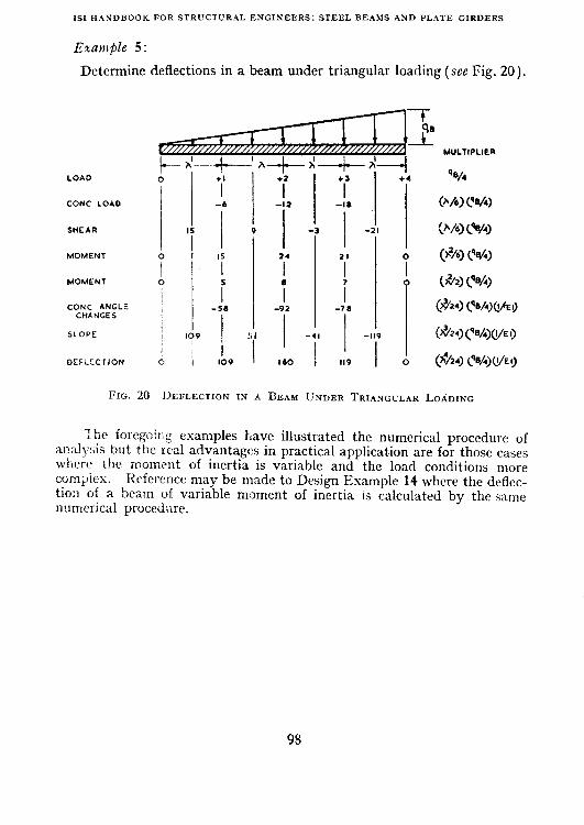
ISIHANDBOOKFORSTRUCTURAL ENGINEERS:STEELBEAMS AND PLATE GIRDERS
Example 5 :
Determine deflections in a beam under triangular loading (see Fig. 20).
LOAD
CONC LOAO
MOMENT
MOMENT
I CONC ANGLE -SO
CHANGES
SLOPE IO? / I
OEFLECTION 6 I lb9
s +2 l 3
’ -1. -I2
-3 I
I I-
24 II
I I
i i -92 -71)
I I
-
z -
i
0
FIG. 20 INFLECTION IN A BEAM UNDER TRIANGULAR LOADING
‘“ihc foregoing examples have illustrated the numerical procedure of analysis but the real advantages in practical application are for those cases where the moment of inertia is variable and the load conditions more compicx. Reference may be made to Design Example 14 where the deflec- tion of a beam of variable moment of inertia is calculated by the same numerical procedure.
98
SECTION V
SPECIAL PROBLEMS IN BEAM AND GIRDER
28. GENERAL
28.1 This item covers certain special problems in beam design that are important when they do occasionally require special attention. These problems include biaxial bending of symmetrical sections, bending of un- symmetrical sections, with and without, lateral constraint, bending of the channel section, and finally combined bending and torsion - when to avoid it and how to design for it if one is obliged to do so. Bending in these cases shall not be termed ‘ simple ’ since it may involve deflections in a different plane from that in which the beam is loaded. A general discussion of the more typical problems will be illustrated by Design Examples 4 to 10, together with commentary, concerning the more typical cases that may Abe encountered in practice.
29. BIAXIAL BENDING
29.1 Whenever loads are applied on a beam at an angle other than 90” with respect to one of the principal axes, the beam is under ‘ biaxial ’ bending. The load may be resolved into components in the direction of the two principal axes and the bending of the beam may be regarded as the super- position of the two bending components. This procedure for handling biaxial bending is particularly suited to the case in which there is at least one axis of symmetry since in this case the orientation of the principal axes is known by inspection and the distances from these axes to points in the beam cross-section that should be checked for stress are also immediately apparent. However, when the section itself has no axis of symmetry, such as in the case of an angle with unequal legs, the alternative procedure utilizing the general formulas for bending referenced to arbitrary X and Y axes in the plane of the cross-section is generally preferred. Nevertheless, if the orientation of the principal axes of the unsymmetrical section is determined, the first procedure may be used. Alternatively, unsymmetrical sections subjected to biaxial bending may be analysed graphically with con- venience, by drawing the circle of inertia. Design Example 5 illustrates this method.
30. BIAXIAL BENDING OF A SECTION WITH AN AXIS OF SYMMETRY
30.1 The biaxial bending of a WB or I-section will be used as ari example, The same procedure is applicable to the channel provided it is loaded through
99

IS,H.%!iDROOK FOR STRI!CTURALENGINEERS:STEELBEAAlSAND PLATE GIRDERS
the shear cent.re ( see 37 ). The shear centre is an imaginary line parallel with the longitudinal beam axis through which the applied loads shall pass if twist is to be avoided.
The possible planes of application of the load are shown in Fig. 21. If the load is brought in at-A in the direction shown by the arrow head, the member is loaded by twisting moment as well as in biaxial bending. Com- bined bending and twist will be discussed in 39. If, however, the load is applied at H ( coincident beam axis and shear centre ) it may be resolved into components parallel with the X and Y axes and, since these are principal axes, the normal stress is simulvthe super-position of the effects of bending about the X and Y axes. fn~a~simple span, the loading as shown in Fig. 2i would cause tension at C and compressiou at D. These locations would,
FIG. 21 BIAXIAL BENDING OFSECTION WITH Two AXES OF SYMMETRY
therefore, govern what permissible stress should be used in the design. There is no explicit problem of lateral buckling involved, but if the horizontal component of bending approaches zero, the permissible stress should be governed by the reduced stress Fb as given in Table HA, 9.2.2.2 of IS : t300_ 1956 (see Table II on p. 172 of this Handbook for an extension of the Table in IS : 800-1956 ). However, it is also obvious that if all of the load were applied horizontally in the X-X plane, the full allowable stress of 1 575 kg/cm? should govern as there is no tendency for lateral buckling. As a conservative basis for design, therefore, it is recommended that a simple interaction formula be used in such a case.
(#,+(j+>,> 1 . . . . . . ..I (29)
In Eq 29, fb represents the computed stress due to the two components-of bending moment and Fb is the corresponding permissrble stress if that component alone were acting. In the case of rolled wide flange or I-beams, the permissible stress Fb for bending about the Y-Y axis would always be 1 575 kg/em2. Members with relatively wide flanges,, such as might be used for struts, will be most economical for biaxial bending.
100
SECTION V: SPECIAL PROBLEMS IN BEAM AND GIRDER
The foregoing formula Eq 29 may be considered as an extension of the formula in 9.5 of IS: 800-1956 for combined bending and axial stress. In this case, the axial stress is zero. Sub-clause 9.5.1 in that standard states:
‘ When bending occurs about both axes of the member, fb shall be taken as the sum of the two calculated fibre stresses.’
This provides no gradual interaction for the case under consideration here but when the allowable fibre stress about each axis is the same, the proposed interaction formula for biaxial bending reduces to that stated in 9.5 of IS: 800-1956.
31. DESIGN EXAMPLE OF BIAXIAL LOADED BEAM
31.1 The illustrative design example of biaxial loaded beam is shown in the following two sheets ( see Design Example 4).
101

XEl llANDB0i3~ FOR STRUCTURAL ENGINEERS: STEEL BEAMS AND PLATE GlRDERS
Dcaigrt Exam@Se 4 - Biaxial Loaded Beam
The +xeduvc Jo1 designing a beam with one ov move axes of symmetry under bihxial bendi?? is illufrcilcd. only that phase of design peculiav to biaxial bendirtg is tvpated in this illztstvaLzue example and the deflections. iJn%sived, could also be found as the &f.xvposi- !ioat oJde,ffecttom in the x altd y directions as caused by the loads separately af@icd. Itis to be ltoted that the section loaded as shown in Fig. 19 will noi deject in the plane of the loads.
An I-shaped beam spans 7.5-m beam between sup- ports. At each end it is adequately supported verti- cally and aga.inst twist as shown in the figure. In addition to its own weight, the beam carries 4-tonne loads at the third points and a horizontal load of 15U kg/m.
Estimate weight. of beam @ 75 kg/m
Bes2diug oboui X-X axis
Dead load 1?1,, = ___ 75x7.52 =
8 527 m*kg
Live load .V,, = 4~2.5~1000 = lOOOOm.kg 10 527 m.kg
Bcndiug about Y-P axis:
150 x (7.92 Al,, = __--
8 = 1 055 m*kg
A.s a preliminary guide, determine required Z,, ZYY for M,,, MYY acting separately, estimating fb(xx) = 1 200 kg/cma.
1~_527x100 Zrx = _- = 877.25 cm=,
1200 Z YY =
1055x100 = 67cm” 1 575
Try ISI-113 350, 67.4 kg. Z = xI 1094.8 cm*; ZYY = 196.1 cm8
Ixr: 7.5 x BOO -_ b = --- S 254 30 ’ d/V 3.50
= -1r6 = 301 Fb(zs, = 1 160 kg/cm*
102

SECTION V: SPECIAL PROBLEMS IN BEAM AND GIRDER
Try ISHB 400, 77.4 kg
Z xx
Z YY
1: xx
FbYY
f bxx
f bYY
Section thcck by I?~teuatlion I~ovnutln
10 527 x 100 = = 1 094.8 963 kg/cm*
1 055 = Fj63 x 100 = 537 kg/cma
= 1.2 > 1 -No tiood.
= 1 404.2 cm3
= 218.3 cm3
7.5 = ?j;10 x loo
400 = T2Y7
= 1 123 kg/cm*
= 1 575 kg/cm*
= 10527x100 _ .~- 1 404.2
1 055 = jiG x 100
= 30
= 31.5
= 750 kg/cm2
= 483
= 0.975 < 1 . . . . . OK.
Then check web shear, bearing plate, web crushing, web buckling, etc. for vertical loads in the same manner as for usual beam design.

~S~WANDBOOKFORSTRWCTWRALENGINEERS:STEBLBEAMS AND PLATEGIRDERS
32. LATERALLY CONSTRAINED BENDING OF SECTIONS WITH NO AXIS OF SYMMETRY
32.1 If an asymmetrical section, such as a Z-bar or unequal legged angle (see Fig. 22 ) is loaded in a plane parallel to one of the surfaces, it will, if unconstrained, bend in some other plane. However, if laterally supported by the roof or by other means, the bar may be constrained to bend in the same plane as the load. When so constrained, the stress due to applied loads may be calculated as in simple bending. For example, if deflections are permitted only in the Y-Y plane and the loads are in the same direc- tion, the stress due to bending about the X-axis will be given by the usual beam equation :
. . . . . . . . . . . . . (30)
if the beam is constrained in the x direction at the same points at which it is loaded in they direction, the lateral constraining forces in the x direc- tion will be related to the applied forces in they direction by the ratio of I,,jI, where Izu is the product of inertia. Hence, with lateral constraint:
M Y
- Mx Ix, 1,
. . . . . . . . . . . . . (31)
The product of inertia is not to be confused with the polar moment of inertia and is given by the following equation:
I,, = I
xydA . . . . . . . . . . . . . (32) A
FIG. 22 ASYMMETRICAL SECTION UNDER BIAXIAL BENDING
33. DESIGN EXAMPLE OF ANGLE SECTION BEAM LOADED IN THE PLANE OF WEB
33.1 The illustrative design example of angle section beam loaded in the plane of web is shown in the following two tihects ( SEC Design Example 5 ).
104
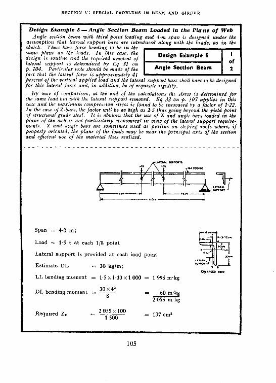
SECTION V: SPECIAL PROBLEMS IN BEAM AND GlRWER
__._ Design Example 5 -Angle Section Beam Loaded in the Plane of Web
.4q$e se&on beam with lhivd point loading and 4-m spau is designed under the assumptio?t that lateral suppovt bars ave intvoduced along with tke loads, as in the sketch. These bavs fovce bending lo be in the same plane as Ihe loads. In fhis case, the design is voutine and Lhe required amount of lateval support is determined by Eq 31 ox p. 104. Particular note should be made of the fact that thr lateral fovce is appvonimately 41
m
percent of 6hr zlevlical applied load and the lateral support bars shaEl Save to be designed for lhis lalrvai fovce and, in addition, be of requisite rigidity.
By way of rompavison. at the end of the calculations Ihe slves,s is determined for Ihe same load b&with the lateral support vemoved. Eq 33 on p. TO7 applies in this case In
arrd the maximum compression stress is found to be increased hy a factor of 1,22. the case of%-bars, the factor will be as high as 2.5 thus going beyond the yield point
of structural gvade steel. II is obvious that the use of 2 and an&c bars loaded in the plane of the web is not pavlicularly economical in view of the lateval stcppovt vequive- merits. 2 aud angle bars an sometimes used as p&ins on sl+i~g voofs where, if properly oriented, the plane of the loads may be neav the pvincipad axis of lhe section and eficielrt use of the malevial lhus realized.
Span .= 4.0 m;
Load = 1.5 t at each l/S point
Lateral support is provided at each load point
= 30 kg/m; Estimate DL
LL bending moment
DL bending moment
CNLARc(D VIEW
= 1.5 xl.33 x 1000 = 1 995 m.kg
= 30x4” 8 = 60 m-kg 2055 m’kg
Required Z, 2 055 x 100 = ~~--- 1 500 = 137 cm3

1st HANDBOOK FO% STRUCTURAL ENGINERRS: STEEL ERAMS AND PLATE GtRDERS
Use ISA 200 150, 15.0 mm angle.
Ix = 20056 cm4 I, = 962;9 cm* ZX = 145.4 cm”
Lateral support requirement to provide for lateral bending moment:
-8185 x 1.5 ~ Lateral force = .--2 oo5.6 = 0.612 t at each load point (neglecting the effect
of dead load) (about 41 percent of the applied load)
What would be normal stress due to biaxial bending if no lateral support be provided 7
(check point A ; y = 6.2 cm x = 3.72 cm)
At A, f = 2055x100
2~56y96~_(818.5)’ -- [(-6.2) (969*9)-(-8185) (-3*72)-j
= -1 46Q kg/cm’ compression
At B, y = j-13.8 cm x = -222 cm
AtB,f = __~os5x100 2 (w5.6 x969.9-(8185)’
(+13.8x969.9)-(-8185) ~(-2.22)
2055x100 = -*T5Ex11 550 = l 860 kg/cm* > 1 500 kg/cm*
(permissible tensile stress)
Thus, if no lateral support be provided, the allowable load gets reduced in the proportion of 1 860 to 1 500 kg/cm* (1.24: 1).
NOTE - As the load assumed here is vcrtkd, there is oo My component. If the load were
inclined, the components ML and My ,should be determined and the stress calculated by Eq 33
and Eq 34 ( see p. 107 ) and added to gwe the total Sbm stress at either of tbc points, A or B.
106

SECTION V: SPECIAL PROBLEMS IN BEAM AND GIRDER
34. UNCONSTRAINED BENDING OF SECTIONS WITH NO AXIS OF SYMMETRY
34.1 The most common example in ordinary use of the unsymmetrical section with no axis of symmetry is the rolled angle with unequal legs. Taking X and Y axes positive in the directions as shown in Fig. 22 and oriented parallel with the sides of the angle, the positive sense of bending moment components M, and M, are shown as chosen in the same figure. In sections of this type, it is convenient to resolve the bending moments due to any applied loads into corn onents about the X and Y axes and calculate the stress due to bending g y the following equations:
Bending about X-axis :
MZ jb = I,Z, - I=,, KY - Iv4
Bending about Y-axis :
. . . . . . . . . . . (34)
If deflections are desired, it is preferable to determine the principal axes of inertia and study the bending problem b-y the same procedure followed fin Design Example 4 for biaxial bending of a doubly symmetrical section.
The derivation of the foregoing Eq 33 and Eq 34 may be fbund in any ad .vanced Ibook on strength of materials, such as Timoshenko’s ‘ Strength of Materials ‘, 3rd ed, Part I, p. 230-231 published by D. Van Nostrand Company, Inc., New York. As exaniples of unsymmetrical bending, both constrained and unconstrained, Design Examples 5 and 6 concerning angle section are presented.
35. DESIGN EXAMPLE OF ANGLE BEAM LOADED PARALLEL TO ONE SIDE
35.1 The illustrative design example of angle beam loaded parallel to one side is shown in the following sheet ( see Design Example 6 ).
107

IS1 HANDBOOK FOR STRUCTURAL ENGINEGRS: STEEL BEASIS b: PLATE GIRDERS
Design Erample 6 -Angie Beam Loaded Parallel to One Side This is alzothcr example of a single angle, used as a beam and loaded i,z a Platte
barallel to ore of its sides. No lateral support is provided. To gel a preliminary !vzal design, the Yequired section modulus for an z&e zerlth lateral support but with the allow- able stress multiplied by a factor of 0.7 is Determined. The properttcs of the angle having !his modultts aye tabulated aud the product of inertia is determilted. There are jive possible
~m
locations for maximum stress as noted by letters A to E. However, if ooze visualizes the zpproximatr direction of the prirlcipal axes of inertia it is obvious that both components gf bending iJ resolved in the directi of the principal axes would produce compvessio+8 zt B azd tension at E. These stresses are calculated by Eq 33 ( see p. 107) and the ma.rimum stresses aye found to be within permissible limits. If there is any question zbout -the location of maxfmum stress in the mind of the designev, it should also be checked at .-l, C and D.
For the u~gle to bend without twzst, lhe resultant of the loads should go through the shear centre which is at the intersection of the middle planes of the two legs. --------------_-----~~~~_-____-~-~___~~~~~~~~--
Y Single Angle as Beam Design
A single angle beam has a simply< supported span of 3 metres with loads given below: Live load = 1.50 t/m
Dead load = 0.20 t/m (including beam weight)
W = 1.70 t/m
.\ngle free to deflect laterally will be stressed more than if held. A4s an approxi- mation, assume unsupported angle has capacity of 0.7~ supported angle
Nx z !:7AGTz z 1.91 m+, permissible streSs = 1 500 kg/cm%.
Required ZX 1.91 xl 000x100
1500x0.7 F 182 ems Try heaviest ISA 200 150,
18 mm section.
46.9 kgjm \vith, Z, = 172.5 cm3, Zy = 101.9 cm3, 1%~ = 958.1 cm*, Ix = 2 359 cm&, fr = 1 136.9 cm4
f = j-i!F;j- (lYy-fIxYx) Maximum compressive stress is at B XY KY (n = +2.34, y = -13.67)
(f&b! = &$$& (-1 136.9x13.67-t-958.1 x234)
= 1 440 kg/Cm’ . . . OK as permissible bending stress for l/r,, = 69 = 1 500 kg/cm*
Maximum teusilc stress at E (x = -3.84 cm, y = 6.33 cm)
f/J(E) = , :‘joo~ (1 136.9 x6.33-1-958.1 x 3.84)
= 1 180 kg/uu? < 1 500 kg/cm2 . . . OK [see 9.2.1(b) of IS: 8OO-19561
108

SECTION V: SPECIAL PROBLEMS 1N BEAM AND GIRDER
36. DESIGN EXAMPLE OF ANGLE BEAM DESIGN BY DRAWING CIRCLE OF INERTIA
36.1 The Design Example 6 of angle beam is now designed by drawing circle of inertia in the following t-wo sheets ( see Design Example 7 ).
109

tS1 H.\‘iDBOOK FOR STRC’CTURAL ENGINEERS: STEEL BEAMS AND PLATE GIRDERS
Design Example 7 - Angle Beam Design by Drawing Circle of Inertia 1~ th:- ~xanzple. the same pro&m as given in Design Example 5 will be soloed
gr~pJ?~~ali~ by drawrng the czrrlr of inertia. The method i? as follows and the con- 5tructiorr IS giver& in the sketch.
The X-X arLd Y-Y axe.? are drawn from the rentvoid G of the angle sech’o~l. Starting from G ox the Y-Y axis. a nvd b aw maukrd such that Ga = Lr and ab = Ivy to art), cowe~ie~lt scale. W’lth Gb as diam&r an-d
m
c as tke cerrtre. the circle of wertin 2s dvawrt. ~yom ‘a’ towards left (as the prodzrct of inertia is rtegatlze isa thzs casr ). ad is draug,i parallrl to X-X axis such that ad = Izy (proditrt of inrrtia ), tide at e akld f.
c arrd d are joirrcd and prodrtced both ways to meet the
arrgle section. .Vow GE a?zd Gf determine the pvhciple axes U-U and V-L’ of the
With reference to X-X and Y-Y axes, g is plofted such fhat its CO-
ordinat~~.~ teprrsent bending moments ~1~~ and Myy givers. III this case. as Myy = 0, g lies oti the X-X axis. If gh and gj aye drawrr perpendictrlnr to the principal axis, these represent resppect~vel~~ the components M,,,, and Msc. From inspection of the orientntlon of the n~glr srrtiorz ZIK~ ~J(c pvc,rcipal as,s. it ?s ,ohviow tfmt maximum fibre stw.t.7 should be checked at pwrrts H and I:. location ijf maximum stress
If tJwye is a,~># qttestzolt about the
A, C md Ii. i,~ the ~li~l of tJrc desig,lrr, if slrolrld also be cJm-.M al
mPa.vLll;: The co-ordinatrs of the:;e points with referewe to the pviw!pal axes aYe
The Jibvc stwss at fkty /wit.< rotlId be drtcrml,r?d as g’“‘n below. .---- -----.----_____.~..__-_--------._---------~----
Y

SECTION V: SPECIAL PROBLEMS IN ~BEAhf AND GlRDER
Co-ordinates of C with reference to
X-X and Y-Y axes (t3.84. +6.33)
Ga = IXX = 2 3594 -cm’
ab = JYY = I 136.9 cm4
ad = 1, = -958-l cm4
ed = ~uu = 2 880 cm4
df = Itan m= 616 cm4
Gg = Mxr = 1.91 m-t (see p. 108)
gi = MU, = 0.9 mt
gh = Muo = 1.68 mat
Co-ordinates of points B and E with reference to U-U and V-V axes are:
6(+48, +130)
E(-65, -37)
= $- 1 450 kg/cm* ( compression )
jE = -1~68~3~7xlOOxl __-.__-__ 000 _ 0~9x4*8x100x1000 _ 2 880 616
= -1 170 kg/cm* (tension)
The fibre stress Is in all cases less than 1 500 kg/cm* . . . . . OK.
It may be observed that the values f, and fE~are very close to those as deter- mined b-y -the method given in Design Example 6.
111

iS1 HA~+DROOK FOR STRUCTURAL ENGINEERS: STEEL BEAMSAND PLATE GIRDERS
37. BENDING OF CHANNELS WITHOUT TWIST
37.1 When a channel se&on is used as a beam with loads applied parallel with the web, i? will bend without twist only if loaded and supported through its shrar ccntre in which case the resultant shear stress in each flange acts hori:<ontally and in opposite directions. The resultant shear stress in the web is simply the total shear at the cross-section due to the exter- nally applied loatls. The web shear and the couple produced by the flange shears may be ru$aced by a single resultant shear force, the location of which determines the shear centre. The location of the shear centre in a channel section may be calculated, in reference to the dimensions shown in Fig. 23 by the following Eq 35 for sloping and parallel flange sides, respectively:
X, = x$ ( see Fig. 23 for symbols ) X2
. . . . . . . . . . . (35)
It~is usually impracticable to load a channel through its shear centre although it has been done in some special cases where the peculiar properties of the channel section h;rve actually been utilized to advantage. A channel may be constrained agaiilst twisting~at the load points and supported at its ends ap- proximately at the shear centre location, as shown in the Design Example 8. The channel may then be treated as if it were being supported and loaded along its shear centre with restraining moments supplied at framing beam connections so as to apply the load resultants effectively at the shear centre.
FIG. 23 SHEAR CENTRE OF CHANNEL SECTION
38. DESIGN EXAMPLE OF SINGLE CHANNEL AS BEAM
38.1 The illustrative design example of single channel as beam is shown in the following two sheets ( see Design Example 8 ).
112

SECTION V: SPECIAL PROBLEMS IN BEAM AND GIRDER
Design Example 8 - Single Channel as Beam The plan and elevation views show that the channel is loaded at its third points
with au effectirre span of 6 m. A stiffenev at each support point centralizes the beav- ing pad vfaction under the shear centve. tiou A-A shows the manuvv in. which the beams
sec: are to be welded to the web of the channel The beam weight is estimated and the moments due to dead and applied loads along with rrquived section modulus ave calculated in the
m
~tsrral manner. In the case of a single channel, the specification pevmits only 1 500 kg/cm’ as the pevmissibte stress. A channel with the required section modulus is selected and the allowable stress is checked for the 2-m unsupported length at the centve. Tke skear centve is located by Eq 35 and found to be 3.09 cm from the centve plane of Ike web ov 272 cm from the back of the web. The ends of the framing beams, assumed lo be ISLB 300 s&ions, ave checked for connection and coped section strength at a-a znd b-b. Tke weld along a-a is checked to’make sure of its capacitv to trausit the moment tkat will be developed by the tendency of the channel to twist. ?he stress along !inc b-h, at evul of coping. is also checked fov eccentricity of 15.96 en.
For a discussion of shear centve in more unusual shapes, reference may be made !o Timoshenko’s ’ Strength of Materials ‘, 3rd ed. Part I, p. 240, published b D. Van Nostrand Company, Inc., New York. _-_-_---___--_------- -_-----------__--__________
ELEVATION
Single Ckannel as Beam
A channel beam is designed for loading as shown. Clear span = 6 m
Estimate beam weight = 45 kg/m.
Moment due to cone load = 3.2x2x1000 = 6400 m*kg.
“;;;it,i;; tz 45 x 6= 8
= 202.5 mvkg = 6 602.5 m*kg
Required Z = ’ ““,“‘:$,‘” ENLARGED SECTION AA
=4402cma
113

ISI HANDBOOK FOR STRUCTURAL ENGINEERS: STEEL BEAMS AND PLATE GIRDERS
use ISLC 350, 38.8 kg
z ZI = 532.1 cm*
CYY = 24l cm
I *z = 13.72 cm
b = 1OOmm
‘I = 12.5 ~rnrn
h = d-9 = 33.75 cm
iw = 7.4 cm
XC = CYr--to/2 = 2.04 cm
Check allowable stress for 2 m ,unsupported length.
200 l/b = 1. = 20
By re&rence to IS: SO&1956 conservatively applicable to single channels, allow- able strum is 1 500 kg/cm*. Beam selection is. therefore, OK. Locate shear centre.
3.09~@37 = 272 cm from back of web, thus locating the effective location of supports and loads for cases where rotation is not permitted.
Design connecting weld between ISLB 300 webAid channel web for an eccen- tricity of 2-72+074 = 3-46 cm [see ISI Handbook for Structural Engineers on Welded Gmnections for Design (under preparation)].
Check stress at end of coped ~edion (b-b in sketch) for eccentricity of 125-i-2-72 = 15.22 cm.
M = 15.22 x3.2 = 4.87 cmet
Section modulus of coped web 25 x67 cm
g = 067 - x25’ 6
= 70 cm’
f =v = 696 kg/cm* < 1 500 kg/cm*
Ckeck end deaf:
“;“~~60 x $ = 286 kg/cm* < 1025 kg/cm* (see 9.3.1 of IS: 800-1956) . . . OK
If web of chaunel is welded to its supports at each end, weld should be design&
for an eccentricity of 3.09 + @$’ = 346 cm.
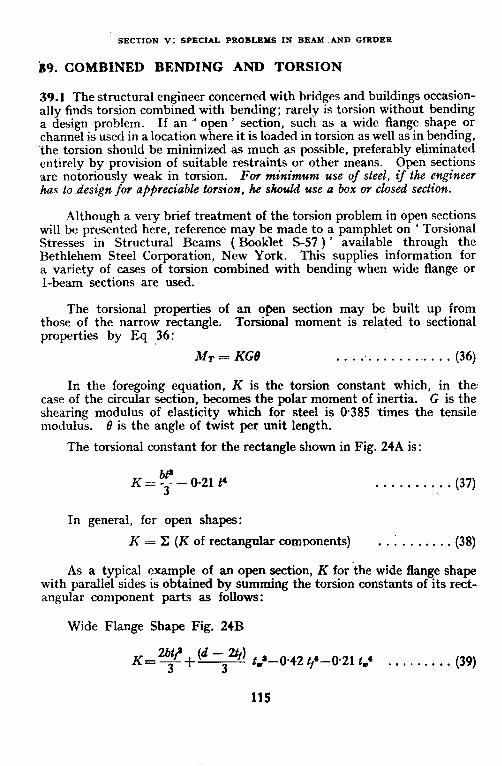
SECTION V: SPECXAL PROBLEMS IN BEAI AND GIRDER
b9. COMBINED BENDING AND TORSION
39.1 The structural engineer concerned with bridges and buildings occasion- ally finds torsion combined with bending; rarely is torsion without bending a design problem. If an ~‘ open ’ section, such as a wide flange shape or channel is used in a location where it is loaded in torsion as well as in bending, the torsion should be minimized as much as possible, preferably eliminated entirely by provision of suitable restraints or other means. Open sections are notoriously weak in torsion. For minimum use of steel, if the engineer his to~desig+z for appreciable torsion, he should use a box or closed section.
Although a very brief treatment of the torsion problem in open sections will be presented here, reference may be made to a pamphlet on ‘ Torsional Stresses in Structural Beams ( Booklet S-57 ) ’ available through the Bethlehem Steel Corporation, New York. This supplies information for a variety of cases of torsion combined with bending when wide flange or I-beam sections are used.
The torsional properties of an open section may be built up from those of the narrow rectangle. Torsional moment is related to sectional properties by Eq 36:
MT = KG8 . . . :. . . . . . .-a.. . (36)
In the foregoing equation, K is the torsion constant which, in the case of the circular section, becomes the polar moment of inertia. G is the shearing modulus of elasticity which for steel is O-385 times the tensile modulus. 0 is the angle of twist per unit length.
The torsional constant for the rectangle shown in Fig. 24A is:
K=!f--021t4 3 .
. . . . . . . . . . (37)
In general, for open shapes:
K = Z (K of rectangular components) . . i . . . . . . . (38)
As a typical example of an open section, K for the wide flange shape with parallel sides is obtained by summing the torsion constants of its rect- angular component parts as follows:
Wide Flange Shape Fig. 24B
K_-bt? I (d - %) 3 3
t,‘-0.42 tf’-0.21 tm4 . . . . . . . . . (39)
115

IS-I HANDBOOK IORSTRI'CTURALENGINERRS:STBRLBE_4MS dNDPLATE GIRDER9
FIG. 24 TORSION OF OPEN TRIN SECTIONS
The stress due to torsion is given for either the wide flange or rect- angular shape by Eq 41:
fim,, = M!!I . . . . . . . . . . . (40)
When loads cause a combination of torsion and bending, in a wide flange beam, the torsion is non-uniform. Longitudinal normal stresses due to localized torsional flange bending stresses are developed which add to the normal stress due to bending calculated in the usual manner. .
When the objective of saving steel is paramount, one should avoid ex- posing open sections to torsion. Attention will, therefore, be turned to the torsional properties of the box section with a subsequent comparison to the open section.
The torsional moment resisted by a simple rectangular bos section as shown in Fig. 25 is as follows:
hfT = 2zehf& . . . . . . . . . . . (41)
where fT = Allowable torsional shear stress. The associated torsional constant for the same section is:
. . . . . . . . . . .
s is any distance along the periphery along which t is constant.
116
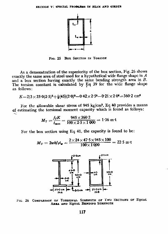
SECTKON V: SPECIAL. PROB&BUS IN BEAM A!iD GIRDER
FIG. 25 Box SIXTION IN TORSION
As a demonstration of the superiority of the box section, Fig. 26 shows exactly the same area of steel used for a hypothetical wide flange shape in A and a box section having exactly the same bending strength area in B. The torsion constant is calculated by gq 39 for the wide flange shape as follows :
K=2/3 x250(25)~+~(45)(2~0)*-0.42~ 2*5’-@21 x 20’=360.2 cm*
For the allowable shear stress of 945 kg/ems, Eq 40 provides a means of estimating the torsional moment capacity which is found as follo\?rs: <
M* ,fE = 945x360.2 dax 100x25x1000= 1-36mSt
For the box section using Eq 41, the capacity is found to be:
MT = 2whf& = 2x24x47*5x945x100 = 22.5 m.t
100x10.00
FIG. 26 COMPARISON OF TORSIONAL STRBNGTH OF TWO SECTIONS OF EQUAL ARSA AND EQUAL BENDING STR~NGTK
117

ISIHANDBOOK FOR STRWSURALENCINEERS:STEELREAYSANDPLAIE GIRDERS
Thus, exactly the same amount of steel provides ‘$8 = 16.3 times as much
torsional strength in the box as in the open section. The torsion constant K for the box section is obtained from Eq 42 as:
47 700 Thus, for equal area, the box is found to be 3602 = 132 times more rigid
than the wide flange shape.
If the wide flange shape were loaded to approximately l/16 the torsional moment of the box so as to make each have approximately the same tor- sional shear of 945 kg/cm*, the wide flange shape would twist 8 times as much as the box of the same length.
The foregoing comparison applies only to *uniform torsion and not to combined bending and torsion. In combination with bending, similar relations would apply but the differences between the two behaviours would be reduced slightly.
The longitudinal stresses developed in the Aanges in the case of uniform torsion of wide flange shapes introduce a complex and serious design limita- tion that is relatively absent in ~box section of proportions required in heavy steel structures. The following design example will demonstrate the actual design procedure that might be followed if and when the torsion problem could not be avoided in a steel structure.
Finally, an important attribute of the box beam, because of its great torsional rigidity, is the fact that it may be used within reasonable limits with no stress redu&ion when laterally unsupported.
40. DESIGN EXAMPLE OF BOX GIRDER FOR COMBINED BENDiNG AND TORSION
40.1 The illustrative design example of design of box girder for corn- bined bending and torsion is shown in the following two sheets ( see Design Example 9 ) .
It is noteworthy that even greater torsional loads might be carried than those assumed in the design example with no apparent penalty to the bending strength of the box girder. This illustration amply demonstrates the importance of using a box section when torsion has to beincluded with bending in a design problem.
118

SECTION V: SPECIAL PROBLBMS IN BEAM AND GlRDER
Design Example 9 -Box Girder for Combined Bending und Torsion As shown in the sketch, tke box girder is~of 5-m span and carries a wall load of
l-8 tonnes per m&e. .4 t tke centre, there is suspended a monorail I-beam hoist that cantilevers out 1.2 ml to either side of the box beam. The monorail koist beam is first design- Design Example 9 I ed as a simple car&lever beam so as to obtain tke dead load that it adds at the centre of the Box Section for Combined of
box beam. The bending moment in the box Bending L Torsion 2 beam is now calculated and the required section modulus for bending alone determined on the basis of an allowabk stress of 1575 kg/cm’. If the box were ~built up entirely of plates wetded along 4 iongitudinal lines, the allowable stress should probably be 1 500 kg/cm* but it is planned to use two channel sections to form the bon and in this case a liberal interpretation of tke code would indicate an allowable bending stress of 1 575 kg/cm’. _ 1
Hoist load = 5 t
Weight of hoist = O-6 t
Rending moment in I-beam for monorail hoist (assume effective length = 1 m in consideration of
’ bracing provided )
5x1 xl00 = 500 cm-t
Impact 100 percent = 500 cm+ 1 Ooo cm-t
DLO~6xlx1OO = 60 cm-t 1060 cm-t
Required Z = 1060x1000
1 575
= 674 ems
Use ISLB 350.
Z = 751.9 cm* for tbe hoist.
For the main girder, choose box beam for best torsional capacity. Make initial selection for bending alone with subsequent check on torsional stresses.
Bending moment
Masonry wall 1.8 t/m = 1.8s” 5’, 100 = 5625 cm-t
Box beam, estimated weight
0.12 t/m = O*l2x5’,1OO = 37-50 cm-t
8 Hoist weight+load+impact
=llt,say = 11X5X100
4 = 1 375 cm+
Total = 1975 cm-t
Required Z = ’ 9~~7~000 = i255cm*
119

XSt HANDBOOK FOR STRUCTURAL ENGINEERS: STEEL BEAMS AND PLATE GIRDERS
TWO ISLC 400 channels supply a total sec- tion modulus of 1399 cm3 and should be satis-
Design Example 9 2
factory when welded np continuously to form a of box as shown ia section on this sheet. Plate
Box Sectton for Combined diaphragms should be welded at each end to
Bending & Torsion 2
maintain the shaue of the box and distribute both vertical and torsional loads to the reactions. to prevent corrosion.
The box should be made air-tight h’ote that prior to welding the edges of the channels, they should
veceive a flame bevel cut and small steel bark up strips should be tacked on the inside so that a full penetvation butt weld can be made from the outside only. Since it will be impossible-to weld internal diaphragms in this box, such as would be necessary on a large box section made np of 4 plate segments, theve should be external stiffenev plates provided as shown in the sketch on Sheet 1 adjacent to the location where the I-beam is suspended. Diaphragms did little ov nothing directly to the torsional strength or rigidity aside from this incidental contribution. due to bending alone is now determined.
The shear stress in the box girder This will be additive in one web to the
shear stress due to torsion and will be subtractive in the other web. Thus, from the allowable shear stvess of 945 kg/cm2 there is subtvacted the shear stress caused by berrdirrg. The remainder ds the permissible shear stress avaihble for torsional capa- city which is calculated by .Lq Il. The applied torsional moment which is distributed one-half to each end is found to be amply loss than the torsional capacity. The shear stress irt the web due to torsion is detcrminrd and added to that caused by bending with a resulting total of 718 kglcmz. If the total slrcar stress were closed to 945 kg/cm’. it would be dcsirablc to &heck for combined normal stress due to bending and shear near tltc top of the section according to 12.2.3 of IS: 800-1956.
Theve is no need to check the shear stress in the Pange since this is Gonsiderably thicker than the web. It is tG be noted thai in a closed box section the maximum shear stress due to torsion is at the thinnest portion whereas in an open section the maximum shear is in the thickest portion.
-- -----____________---- -_---------_-_-___‘__-___
Try t\vo 1Sf.C 400 welded toe to toe. Z = 699.5~2 = 1 399cm8 I’ovsion capacity :
TACK
WELOEO- p4 mm
BACKING STRIP FOW WELOING
Average shear stress due to simple bend- ing 1,’ = 55+1*92x25 = 10.3 t (including imnactl
f, = ‘10.3 x 1 000 2X4OXO+I
= 161 kg/cm’
Available shear for torsion = 945 -161 = 784 kg/cm’
Torsion caoacitv : 1 s
784 M, = 2x19~2x38~6x1~xo’g
= 930 cm-t (see Eq 42) Torsional moments applied :
llXl~2Xl~ = 660 cm.t
2 < 930 cm-t . . . . . OK.
Maximum shear stress in web due to bending = 161
Due to torsion = EG x 784 = 557 718 kg/cm’
120

SECTlON V: SPECIAL PROBLEMS IN BEAM AND GIRDER
41. DESIGN OF CRANE RUNWAY SUPPORT GIRDERS
41.1 The repeated loading and unloading of crane runway girders products a very impoitant maintenance problem. There is considerable literature on the subject based on mill building experience. If it isl)ossible to minimize the differential building settlements, crane runway girders may well be continuous since the .flesing of the rail over the support is reduced and the crane itself will have a smoother motion. It is outside the scope of this handbook to go into all of the maintenance problems and special devices that have been suggested for their reduction but reference may be made to ISI Handbook for Structural Engineers on Steel Work in Cranes and Hoists ( under preparation) and to pages 194 to 208 of ’ Planning Industrial Structures ’ by Dunham, a previously cited reference.
The design example presented herein is essentially one of biaxial bend- ing under a moving load and is, therefore, similar to Design ?Qiample 4. However, since lateral load is introduced at the top of the/beam because of inertial forces resulting from acceleration of the trolley and lifted load transvcrsc to the direction of the crane runway, torsion is developed in the crane girder. To compensate and minimize the problem of combined bend- ing and torsion, a channel is very often ri+eted to the top flange of an I-beam. The bottom flange of the beam is omitted as far as transverse load cal- culations are concerned. We then have a situation where a channel iq loaded reasonably near its shear centre. The transverse loads are relatively small and the error involved in this simplification is not serious. The design example to be presented herein represents this type of solution to the crane runway girder problem atid the design will be for a simple beam. The WB plus channel section would not be suitable if a continuous beam were used because of the change in sign of bending moment over the support. It is recommended that if continuous crane runway girders are employed, the possible use of the box girder construction be investigated. For the design of a box girder under combined bending and twist, reference may be made to the previous Design Example 9.
42. DESIGN EXAMPLE OF CRANE RUNWAY SUPPORT GIRDER
42.1 The illustrative design example of cranerunway support girder is s‘hown in the following five sheets ( see Design Example 10).
121

IS1 HANDBOOltFORSTRUCTURALENGINEERS:STEERS:STEEL Br;AMSAkD PLATE GIRDERS
Design Example 10 - Crone Runway Support Girder Ii is assumed that in a long mill building wilh 24 m spar cranes of 10 tonnes
capacily. the runway girders will be suppovisd as shown in Se&on A-A al fhe bottom of lhe sheet and a 30-kg/m rail will be bolted 1 lo Me top jhngc by mca~s qf rail clips. It is Design Example IO I assumed that there arc Iwo cranes and ‘the design shall be based on fherr joint *evalion ? of
with close wheel spacing as shown in Ihe Problem Cited 6 sketch. A play view is also provided wilh I bends shown at 9 m centre Lo cenlrc. ___-----------__----_~~~~~~~--~ ___-____ _____-- -I
Crane Hunway Support Girder Design
The problem is to design the crane runway girder to be used in an industrial building. The sketch shows a partial plan of the crane runway together with other pertinent information. The following are design cqnditions and requirements:
1) The crane girder is a simple beam to be seated on each end, and 2) The girder section is to be built up from a wide flange shape. and a channel
using 20-mm rivets.
111.:,iic,.,..--‘-.-‘- r
i PARTIAL PLAN OF CRANE BAY

SECTfON V: SPEClAL PROBLEMS IN BEAM AND GIRDER
Design computations moment and shear are to be noted that the loads for maximum moment are positioned as shown in the sketch here. The trolley is assumed to be as close as possible to one support of the 24-m spa% maximum load ox the crane re~~w~y girder. ,_______-----------_-~-- ---_- --_-_ ---___________.
Crane capacity = 10 t Weight of crane including trolley = 20 t Weight of trolley alone = 4 t Determine maximum bending moment. Total crane girder weight = 16 t
,.zm u,n
POSTION OF CRANE TROLLEY FOR MAXIMUM CRANE RUNWAY GIRDER LOAD
L!I about B and solving for HA: R, = 22
This load
= 21.3 t
For maximum moment in 9-m span, 3 wheels (31.95 t) will be on span. Place centre of gravity and one wheel equidistant from centre line.
To locate centre of gravity--EM about (1) of (l), (2) and (3) should be divided by the total of the three wheel loads to give:
10~65~3~5+10~65~(3~5+1~2) = 2.,3 m from (1) 3 x 1065
3.5-2.73 :. Distance of centre of gravity from (2) is 2 = 0.39 m*
R A
= 3 x 10.65 x4.89 9
= 17.4 t
Xt (2), Mmar = 17.4 x489-10.65 x 3.5 = 47.7 m-t Plus 25 percent impact = 11.9 met
Live load moment = 59.6 m’t -----___-____________---__________--------------
*sea Sketch.
123

IS1 HANDBOOK FOR STRlJCTtiRAL ENGINEERS: STBEL BEAMS AND PLATE GIRbRRS
In this sheet, after cakulaling the bending Dosign Example IO 3 soment due to horizontal load, an approxima- ion of the required section modulus is obtained of
y dividing the bending moment due to uerticat Praliminuy Dwign 5 sad by the allowable stvess in the tension flange. ‘he section modulus for tensile stress will be changed bul Iiftle by ihe addition of Ihe hannel ta the top jlange since Ike distance from the neutral axis will be increased while the moment of inertia is lihewise increased. No deduction is made for rivets in he top flange bul full deducliort for the drilled kales fov the ZO-mm rail clamp b&s hall be made in determining the stress in tbe compression flange. The compressive tress in Ihe top fEange due to vertical loads is deletmined and the compressive stress br Lateval loads is calculated with the assumplion that all lateral loads are taken by the hannel and top flange of the wide flange shape. __--_-___-___--c____________i___________~ ___-__.
DL Rail 30 kg/m = 0.03 t/m Assume beam weight @ 200 kg/m = 0.20 t/m
>I_ bloment _ 0-- =
O-23 t/m
233 met. Total vertical moment = 61.93 mat
horizontal load = 10 percent of 14 t (see 6.2 of IS: 875-1957) = l-4 t
?er wheel = ‘3
= of35 t
Horizontal moment = 1o_65 = x47.7 x loo
= 157 cm-t (by proportion) ipproximate required 2 (due to vertical bending moment only)
61~93xlOOOx1OO = 1 57s
= j930~cm* Try ISWB 600, 1451 kg and ISLC 300, 33.1 kg
ISWB 184-80 0 - 8.2. 4SwJ 115626.6
I,y bP4 = 2709O+i15 972.6 = 143 062.6
I,+ (net) 143 062.6 = 2 x 2.1 x 3.03 x (23.95)’ (for 20-mm rivets)
= 135800cm4
Z Iuet 135 812.6
ez = y = --25.47 i 5 320 cma
fbzz = .61~93x1OOxlOOO
5320 = 1 162 kg/cm*
For top &Iange and channel only:
Gross Iyy = F+, 047.9 = 8 697.1 cm4
Net 1~ = 8 697-l-2 x 21 x 3.0 x 7’ = 808Ocm*
124

SECTfON V: SPECIAL PROBLEBIS IN BE.4Bl ASD GIRDER
Since section is ~rnsymmetrical about the X-X axis, the permissible stress under vertical loads
Design Eramplo IO -4
shall be determined b.v use of E-3.1 of AQQM- ,
of dix E in IS: 800-1956 w Table LII in this Chock of Preliminary handbooR. It is fortnd. however, that the Design 5 allowable stress by the tables in Appendix E * of IS: 800-1956 zs above the maximum permissible stress of 1 500 kg/cm’, a,td #he latter. #Jrerr,jore. govrr~. The Problem #her% is simplz~ one of combilzi)tg. the two stresses. Had #J&e allowabte strcsscs beeu differerzt. ILe iuteructiott formula proccdrtre suggested previoltsly iit I.Lig~:rr IT.rampJ~ -I would Aavc brat rcyonr&ndcd. ## is uow rrecraear_y to c kerk ilre fctr.G#e .q#ress due.#o vertical bending alone and tlris is fotrtld to be I 520 kg/cm’. l‘kc acllowuble S#~CSS JW a rolled sec#io,r of I 575 &/cm’ is assamed to govern on the tension side, so the selection is satisfactory. _-__-_----------------------.---_-______________
ZYY 8 080
= - f: ,5
540 cm*.
f 157x1 ooo
byy = -x--- .- = 290;8 or say 300 kg/cm’
To determine final F,, use Appendix E of IS: MO-1956 or Table III of this handbook, \vhich should not exceed 1 500 kg/cm* nor C = A +R,B
M for the purpose of Table XX of IS: 800-1956 s .!?.%‘_ = 0.7~ 11 346.2
R, = O-266 (see Table XX of IS: 800-1956)
r,,,, for the whole section = J
11 346.2 -___- = 7.05 cm 42.11+184.86
128, Flange area = 42.11+25x236 = 101.11 cma
ic 101.11
= _jO = 3.37 cm (for N = 1, k, = l), d/#e = @G = 18
Using Table XXI of IS: 800-1956 or more conveniently Table IV, for I/r = 128, d}te = 18, C = .4+&B >l 575 kg/cm* * . . 1 500 kg/cm’ controls design (see 9.2 of IS: 800-1956)
.\t point C. 9.5.1 of IS: 800-1956 provides
1 162-I-300 1462
c j$ *; 1
. - _ =
. . 1500 1500 0*97<1 . . . . . OK.
Ckrck tertsik stress (b”dl;;“oz I, vertical load only)
7 aIx (tension) = ___ 35.2
= 4070cm*
fb (tension) = 61.93X&
4 070 = 1 520 < 1 575 kg/cm* (Allowable stress
for rolled wtion . . . . . OK) I
Check weight assrrmed. ISWB
- %: lrglrn Channel = . Rail = 300 Fittings = 7-5
215.7 knlm = O-22 t/m aDDroximateIv eaual to 0.23 t/m
, _.
’ a&i&d in the-design . . . . . dK.
125

ISI HANDBOOK FOR STRUCTVRAL ENGINEERS: STEEL BEAMS ASD PLATE GIRDERS
In order lo determine Ihe river Pitch, Ihe maximum shear al various points along the girder shall be calculated. II ts rouvcnient to determine the maximum skeat at mefre infer- uais by use of the influence lrnes as shown on
1 DdgnI$ple IO 1 4
this Sheet. The summaliou of injuence [WV co-eficients for maximum shear at the successive points between Ihe centrc line and one end are !ahulaled and since maximum spacing condtllons are apt lo govern ratkcr Ihau stre\s reqrtiremcnls, Ihe l&mm rivets are irled out irr tAe design. 20.mm rivets could be used i/ preferred. It Irtm.i oul, because of tJ~r lrghl loada. whtch were purposclv selected. tkal Ihe rrvel stress requrre- menls do not govern al any point along Ihe girder. T/W co&rolling faclors are Ihe code requirements for a maximum spartn~ at Ihe ends of six limes Ihe rivet diameter and a maximum in line pitch not lo exceed a pdch thickness vatio greater lhan 16. Since further aspects of ihrs design duplrrate procedures Ihal were previonsly presented, they are omitted Jrrre, bul .finaI nole is emphasized that fhe holes should all be drilled after assembly lo mtnimiz the possibility 0J Jaligue cracks developing under repealed load.
------------__-_----____________________--~-~---
Betermine rivet pirch
Maximum shear required calculate at one-metre intervals and at Q
Influence coefficients for maximum shear at: A : (9+55+4.3+0.R)/9 = 19.6/Q B: (R+4.5 +3.3)/Q = 15+3/n c: (7+3.5+23)/n = 12+3/Q
(Power driven shop) rivets:
D: (6+2Gi+la)/Q = 9+3/e E: (5+1.5+0.3)/u = 0.8/R F: (r~o+l~)/e = 5.519
Shear 2-16 mm rivets SS = 2 x 17’ x f xl 025 = 464 t (sre Table IV of IS: 800-1956)
Bearing = 2x17~067~2360 = 5.38 t
Try 6 x2.0 = 12-mm pitch (for 20 mm diameter rivet see 25.2.2.4 of IS: 800-1956). Maximum in line pitch governed by P/f”& = 16 (for intermediate length) P = 16 xO.67t = 10.7 cm < 12 cm. Hence use lo-cm pitch throughout the length 21-mm holes for rivets to be drilled after assembly by clamps. \
For bearing, local crippling:. etc, see Design Example 1.
*Live load = 10&5 t+25 percent impact = 13.31 t:.l%SlXl*6/9 = 29 t. tWeb thickness of ISLC 300 = 67 mm.’
126

SECTION VI
PERFORATED AND OPEN WEB BEAMS
43. OPEN WEB JOISTS AND -BEAMS
43.1 Open Web Joists -There has been phenomenal growth of the use of open web bar joists in overseas countries. These joists, as discussed in IS1 Handbook for Structural Engineers on Functions of Good Design in Steel Economy (under ~preparation ) are not so much designed as they are deve- loped and tested by various individual companies with the aim, however, of complying with certain standardized overall dimensions and load capa- cities for standard span lengths.
With changes in the figure numbets, the following is quoted verbatim from an article by Henry J. Stetina* regarding the detailed application of open web joists in building constructions:
‘ Why are open web joists popular ? The primary consideration ii usually that of costs. This floor system supported on a steel frame and fireproofed according to modern practices is regarded by many engineers and architects to be the most economical construction of all structural sS;stems.
Many factors contribute to this economy. Joists have been developed to a high degree of standardization and are produced by many manu- facturers. The cross-sections of the popular types are shown in Fig. 27. All possess the common characteristic of being interchangeable for any given depth and span. That is so because all joists conform to a standard loading table. They vary in depth from eight to sixteen inches ( 20 to 40 cm ) and are identified by a standard nomenclature.
Joists are quickly installed, braced and welded, as shown in Fig. 28. A cover, such as a metal lath, illustrated in Fig. 29, is then connected to the top flanges, and the lath serves as a form. Besides lath, two other products are in common use for this purpose: a paper backed wire mesh and a light gauge corrugated steel sheet. In the case of lath, it is custo- mary to supply some additional reinforcement in the form of wire mesh as shown in Fig. 30. All of these concrete forms are sufficiently sturdy to support workmen and light construction loads (see Fig. 3 1).
*&S-NRC No. 441. BUILDING RESEARCH INSTITUTE CONFERENCE PROCEEDIXGS ON ’ FLOORS AND CEUJNGS ‘. Washington 25, DC.
National Academy of Sciences, 2101 Constitution Ave.,
127
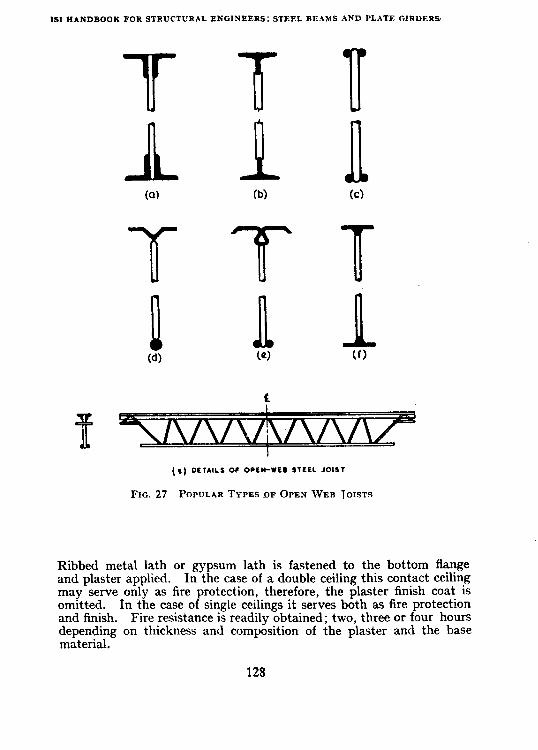
IS1 HANDBOOK FOR STRUCTURAL ENGINEERS: STEEL BEAMS AND PLATE GIRDERS
b)
T T T n n n (4 (0) (f3
(1) DETAIL1 OC OPEN-WEB STEEL JOIE1
FIG. 27 PCGYJLAR TYPES OF OPEN WEB TOISTS
Ribbed metal lath or gypsum lath is fastened to the bottom flange and plaster applied. In the case of a double ceiling this contact ceiling may serve only as fire protection, therefore, the plaster finish coat is omitted. In the case of single ceilings it serves both as fire protection and finish. Fire resistance is readily obtained; two, three or four hours depending on thickness and composition of the plaster and the base material.
128

SECTlON VI: PERFORATED AND OPEN WEB BEAMS
FIG. 28 OPEN WEB FLOOR JOIST INSTALLED AND BRACED
( Photograph by courtesy of American Institute of Steel Construction )
Still another advantage that some builders stress is that the open webs speed up the work of the following trades. .Electrical work and pipes may be more readily installed.’
Figure 32 shows a pleasing use in school building construction of open web joists of the type indicated in cross-section in Fig. 27(a). It will be noted that these are made of four angles with a zig-zag bend reinforcing bar welded between.
129

ISI HANDBOOK FOR STRUCTURlL ENGfXEFRS: STEEL BEAMS AND PLATF GIRD1
130


tS1 HANDBOOK FOR~STRUCTURALENGINEERS:STEELBEAMS AND PLATEGIRDERS
FIG. 31 PLACING CONCRETE FLOOR SLAB ABOVE OPEN WEB JOISTS
(Photograph by courtesy of American Institute of Steel Constructiorb’!
132


FIG. 33 PERFORATED WEB BEAM CONSTRUCTION (Photograph by courtesy of American Institute of Stez1 COIBtNCtiOIi)
134

SECTION VI: PEJLFORA'~ED AND OPEN WEB BEAMS
44. DESIGN OF BEAMS WITH PERFORATED WEBS
44.1 The beam with perforated web is another development which is similar to that of the open web joist. It-is, in fact, an open web joist in itself but is made up out of a single rolled wide flange or I-beam shape by flame cutting the web ‘along a zig-zag line and rewelding the two cut portions to give a beam that normally is 50 percent deeper than the original section from which it was obtained. An esample of this type of construction in practice is shown in Fig. 33. A perforated web beam is suited %o the same type of light uniform load and long span applicatipn as the standardized types of open web joists. The perforated web beam hasnot become nearly as popu- lar in the United States as the open web joist. However, recent tests by Toprac, et al* of a number of perforated web beams substantiate the proce- dures that will herein be presented as Design Example 11. In comparison with the open web joist, the perforated web beam requires somelvhat more welding and would appear to be more wasteful of steel. However, weight comparisons.for similar capacities in a number of spans seem to indicate little to choose from between the two as far as total steel requirement is concerned.
45. DESIGN EXAMPLE OF PERFORATED WEB BEAM
45.1 The illustrative design example of perforated web beam is shown in the folloiving seven sheets ( see Design Example 11 ).
*L\~~~~r~~~s~~, M., COOKE, B.R. AND TOPRAC, A.A. Web Expanded Beams.
iln Investigation of Open U’ctdirlg Jourwl Researclr Sz~pplcment. Vol 22. No. 2,
p. 77-88 ( February 1957 ).
135

IS1 HANDBOOK FOR STRUCTUXAL ENGINEERS: STEEL BEAMS AND PLATE GIRDERS
besign Example 11 - Perforated Web Beam An open web roof beam with peyforaled web 1s designed for a cleav span of lb: metr&s.
he estimated weight of roo$ng. ceiling and fiurlins is 7.5 kg/m2 and the live load is i0 kg/m. The sfiacirtg of the roof brams with ,rfovaled webs wilt be determined bY capacity. y way of compavrson. Descgn Example in the ‘x1 section will be illustrat&ve of the upplira- )n of a tnpcred depth beam to the same loud nditions. The cutting plan is shown on
m
ieet 1. Good practice maintains the depth of the stem of the tee section at the inimum beam cross-section to mu less than one-quarter of the original beam depth
shown in this layout. Where this is done. the over-all perforated web beam depth ill be 50 percent greater than tke original rolled.cection from which it was formed. veal bending stress will be checked rn the tee-section; hence tke need to calculate ctional properties. --_-------------------~----~~_~~_~~~-~~-~~~~~~~
trforaied Web Beam Des&r
lesign an open web roof beam \vith perforated web for clear span of 18 m. oad assumptions:
Dead load including weight of roofing sheets. ceiling, and purlins
Live load = 75 kg/ml = 170 kg/ma
245 kg/m4 pacing of perfvrated \\-eb roof beams \vill be determined by capacity.
Use lSM13 600, 122.6 kg
Calilrlafe j!wopwtj* of tee at op~‘i/ throat:
Area of flange 21.0 x 2.08 = 43.7 cm2 Web 12.92 )\ I.2 = 15.5 cm*
59.2 cma Position oi X.1, by taking moments above top line
.Y = 43.7 ‘( 1.01415.5 x8.54
59.2
= 3.0 cm
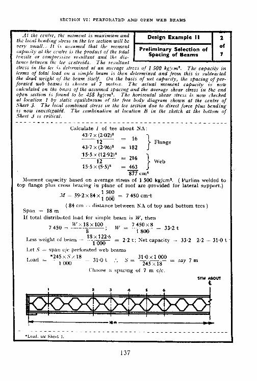
I
SECTION VI: PERFORATED AND OPEN WEB BEAMS
At the renlve, the moment is nzowimum and the local bexding .stvcss in the tee section will be “cry small.. It is assumed that the momerll capa< ity at Ihc untrr i.< the product of the total tensile or compressive resultant and the dis- tance between the tee centrozds. The resultant stvess in the tee is defrvmined at an average slvess qf 1 500 hg/c&. The capacity in terms of total load on a simple beam is then determined and from this is subtracted the dead weight of 1he beam itself. On the basis of net capacity, the spacing of per- forated web beam is chosen at 7 m&es. The actual moment capacity is now calculated on the basis of the assumed spacing und the average shear stress in the end open section is found lo be &8 kg/cma. The horizontal shear stress is now checked al location 1 by static equilzbrzum <!f the free body diagram shown at the centre of Sheet 3. The lot@ combined stress zn the tee section due to direct force plus bending is now investigafdd. The combinalion at location 13 in Ihe sketch at the bottom of Sheet 3 is critical. ----- ____ -_- ---_______ -- -----.--___ -- -___ -__--_--
Calculate I of tee about NA:
43.7x (2.02)* = 16 1
43.7 x’(L) Flange
= 182
lS.S~(lE92)~ _ 216 7 --__
15.5 x:25.5)2 I’ Web
= 463 877 cm’
Moment capacity based on average stress of 1 500 kg/cm*. ( Purlins welded to top flange plus cross bracing in plane of roof are grovided for lateral support.)
.M = 59.2 x 84 x ;-;; = 7 450 cm*t
Span = 18 m ( 84 cm = distance between KA of top and bottom tees )
If total distributed load for simple beam is W, then
w _ Kl!LC! = 33.2 t 1 800
Less weight of beam = 18 x 122.6
= 1000 2.2 t; Net capacity = 33.2-2.2 = 31.0 t
I-et S = span c/c perforated web beams Ioad _ *245xSx18
1000 1.0t . . .
Choose a spacing of 7 m c/c.
SYM ABOUT
t

IS1 HANDBOOK FOR STRUCTURAL ENGINEERS: STEEL REARS AND PLATE GIRDERS
Design Example II 3 Load metre = 245 per x 7 = 1 715
Beam weight = 1226 Check of Combined of
Stresses 7 1 837.6 kg
Maximum end shear = 1 837.6 x 18 = 16.5 --2~xi-ti t
Maximum BM at centre = 29” x 100 = 7 425 cm-t (less than 7 450 cm+ capacity, Sheet 2) . . . OK.
Average sheer at ends:
r, = 16.5 x 1 000
1-2 x 30 = 458 kg/cm% <945 kg/cm* . . . . . OK.
Check horizontal shear at 1 (Refer to sketch on Sheet 2)
Total shear at rl = 16.5 x0.9 = 14.85 t (see sketch here)
Assume compression normal force resultants pass through A and take moments about A (centroid)
42 17, = fi2? x 90
* v, = 15.95 t . .
15.95 xl 000 Shear stressf, = __--
1;2 x 20.0
= 666 kg/cm’ < 945 kg/cm*. . . . OK.
Maximum combined local bending and direct stress in tee segment near l/4 point (Try locations 2, 3, 4 and 5 shown in sketch on Sheet 2) Location 2 :
Shear = 16.5 x0.65 = 10.72 t Moment = 7 425 (l-0.65*) (Moment diagram being a parabola, moment
gets reduced as the square of the distance from = 4 300 cm*t centre.)
lO*Ocm t P --rc
e
VI
Direct stress f, = ~&4~f~4 (area of flange = 59.2 cm*)
= 867 kg/cm* (distance between top and bottom centre of gravity = 83.84)
(Halved because of two flanges at top and bottom.)
138

SECtION Vt: PERFORATBD ANb OPON WEB BEAMS
The sample computation of local bending r !ress due to shear is given at the lop of this
Design Example II 4
leet and the combined stress at each location ; tabulated. The surprising uniformity re-
Check af of
ults f>om the fact that as the average direct combined Stresses 7
!ress in the tee increases towards the ccntve of ‘le span, lht: local bending stress due to s4ear decreases. The combined stress has a zanimum valw of 1 711 kg/cm’. .4lthough not covered by the code, it seems reason2 bte to permit the mawim~rm combined stress to be 1 57.5 kg/cm’ because of its localized .ature. The spacing zs revised to 6.3 metres to bring the stress down to 1 575 kg/cm’.
,4lthough d/tm is less than 85 in the solid portion, the open nature of the web indicates he desirability of adding an end stiffener. A tee section split by ,flame cutting a wide range shape 2s welded in position as shown at the bottom ojSheat 5. __--__-__-____-__-__-~~~~~~~~-__~~ ______ _______
Bending stress at U due to shear,
f so = 10~72x10~0x12 x 1 ooo
2x877. = 730 kg/cm*
Combined stress at B = jc+jsb = 867+730 = 1 597 kg/cm” it 3, Shear = 16.5~0~55 ’ = 9.08 t
XIoment = 7 425 (1-0.W) = 5 180 cm.t
Direct stress at 3, j, 5 180x1000
= T9m4- . . = 1 044 kg/c&
Bending stress due to shear at 61,
f 9.08 x 10.0 x 12
sb = -----_-_~l~
2x877 = 617 kg/cm’
Combined shear at B = jC+jSs-1 O&+617 = 1661 kg/cm* ,it 4, Shear = 16.5 x 0.45 = 7.43 t
Moment -= 7 425 (l--0.45*) = 5 921 cm*t
Direct stress at 4, f, 5 921 xl 000
= -- 59.2 x 83.84
= 1 198 kg/cm%
Bending stress at H due to shear
f sb = 7.43 x 10.0 x 12 x 1 ww)
2x877 = 505 kg/cm*
Cofibined stress at 4 = fc+fsb= 1198 + 505 = 1 703 kg/cm* At 5, Shear = 16.5 x 0.35 = 5.77
Moment = 7 425 (l-0.35’) = 6 51.5 cm?z
Direct stress at 5, j, 6515x1000
= 59.2x 83.84 = 1 318 kg/cm2
Bending stress at B,
j SfJ 5*77x1o~ox12 x 1 ooo
= -1x877 = 393 kg/cmO
Combined stress al 5 = jC+jSa=l 318 + 393 = 1711 kg/cm’ _- - _ __________-_________~~__-~~~-~~~-~ ________-.
*Moment of Ioertia I, SIC Sheet 2.
139
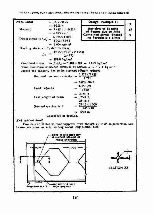
fSt HANDBOOK FOR StRUCTURAL ENCINBRRS: STEEL BEAMS ANLb PLAtE GIdIXd
Momel nt = 4.125 t = 7425 (l-0.25’) _ 6 C-- - 913 cm-t
6 975 x 1000 _
59.2 x 83-84 Erect stress at 6,f0 = -
At 6, Shear = 16.5 x 0.25 1 Design Example I I 1 _
z 1 &4 kg/cm* Rending stress at B, due to ,shear
f 4125x10x12x1 000
.sb = 2x877 = 281.0 kg/ems
Combined stress = fc+fJa = 1404+281 = 1685 kg/cm* Thus maximum combined stress is at section 5 = 1 711 kg/cm* Hence the capacity has to be correspondingly reduced.
Reduced moment capacity = 1 575x7 425
1 711
Load capacity
= 6 850 cm-t
6850x8 =-i-SK
Less weight of beam = 30.40 t = 2.24 t
XiG
Revised spacing is S 28*16x 1 000
= 245 x 18
= 637 m Choose 6.3-m spacing.
End support detail Provide end stiffeners over supports even though d/t < 85 as perforated web
beams are weak in web bending about longitudinal axis.
SECTION XX

SECTION VI: PEXFORATED AND OPEN WEB BEAMS
Previously cited tests ( see 44.1 ) have shown !ha?, for this type of perforated web beams of !he proportions used in this design, the bending dflection of the beam may be approximated ori !he basis of the average moment of inertia of the solid and perforated sections. The deflection as a simple beam i’s found t.7 be 52 cm.
Since tests and more accurate studies of the local deflection show that the local effect is a relatively small one, it is possible to estimate roughly the magnitude by calculating the local bending deflection due to shear as follows:
The de&lion of a tapered cantileeer. length
rn+i may be approximated by a constant ( minimum
section ) cantilever ( skown by dashes in the sketch ) m+n
of length 2
Deflection of cantilever =
In each perforation panel, deflection will be doubled, hence, per panel
6
” = y(mi-4’
24 EIT . . . . . . . . . . . . . . . .
l.et ~5 = xumber of perforation panels in a half span.
Va~g p (m+u)* Total 6v = -mm-24EI . . . . . . . . . . . . . . . .
T
(43)
Using Eq 45, the deflection due to localized tee section bending is found to be 0.16 cm. The total rf centre deflection is now Estimated at 5.36 cm and it would prcbably be desirable to ~give a perforated web beam of this type a camber of at least 3 cm to avr‘id unsightly sag.
. __-_----_-__-_____-_-~--~~--~~--~~--------- - ____
Check deflection :
Base beam bending deflection on average I of solid and open sections above the centre line, plus estimate of local bending deflection.
Perforated section:
I = 2~59.2~42~ = 208 000
+ 2 x 877 (see Sheet 2) = 1 754 209 754 cm’

ISI HANDBOOK FOR STRUCTURAL ENGlNBERS: STEEL BEAMS AND PLATE GIRDERS
Solid section:
Z of perforated &am = 209 754
+ 1.2xw 12
= 21600 231 3.54 cm’
Average 1 = 220 554
*30.4x1 SW:<1 000 Deflection due ti general bending = g4 x -2 050 oooxw
= 52 cm
30.4 V at ends = -. t
V at centre = 0
- v . . avg = [y+o] f = 7.6 t
p = 10 (w+n) = 450 mm
E = 2050000 kg/cm*
I: = 877 cm’
IMiection due to localized tee section bending from Eq 43
_.* & = ;g!ggL?Lg
= 0.16 cm
Total dePicction at centre = 5.36 cm
Camber 3.0 cm ( Dead loadfpart of Live load ).
142

SECTION VII
TAPERED BEAMS
46. INTRODUCTION
46.1 A recent pamphlet entitled ‘ Welded Tapered Girder ’ distributed in 1956 by the American Institute of Steel Construction has focussed atten- tion on the growing use of roof girders of tapered depth. The introduction to this pamphlet, reproduced below with change in figure number, describes this type of construction and its advantages in a way that cannot be improved upon :
‘ In recent years tapered girders fabricated by welding plates together have become increasingly popular in the framing of roofs over com- paratively large areas where it is desirable to either minimize the number of interior columns or to eliminate them altogether, dependent upon the vSidth of the building. The two halves of the web-are produced from wide plates, with little or no waste of material, by making one longitudi- nal diagonal cut. These halves are then rotated and spliced to give the maximum depth at mid-span. When camber is required, it may be obtained very simply by skewing the two halves slightly between their abutting edges before making the splice.
Roof loads being relatively light, tapered girders may generally be fabricated from plates the thickness of which is limited only by avail- ability and the maximum web depth-thickness provision of the AISC Specification.
When the girders are used with the sloping flange up, their taper in both directions from the ridge provides the slope that may be required for drainage. Furthermore, by varying the end depth of successive girders the deck may be canted to drain toward roof boxes in the valleys between adjacent gabled spans and at flanking parapet,walls, thereby eliminating the necessity for crickets.
For flat roofs the girders are inverted, the tapered flange being down. Some other roof designs frequently call for a gable ridge in the centre span of three spans across the width of the building. In such a case inverted girders are used in the outside spans thereby continuing the same slope of decking to the walls.
There are also additional advantages. Economy is realized in dimini- shed overall height of exterior walls as a result of the reduced depth of web at the ends of the girders. Also when used as the principal carrying members for ordinary joisted roof construction above, and a fire retardant ceiling below, tapered girders provide the tight draft stops re- quired by many building codes as a means of subdividing the attic space. One system of tapered beam construction is illustrated in Fig. 34.’
143
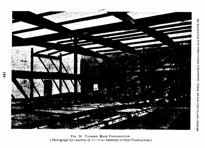

SECTION VII: TAPERED BEAMS
4+. DESIGN EXAMPLE OF TAPERED BEAM
47.1 Tapered beams may also be built up by flame cutting on the skew the web of arolled beam, then reversing thetwo segments and rewelding together with a single straight weld. Design Example 12 to be presented herein takes the same beam that was~made into a perforated web section as Design Example 11 and develops a beam of identical span and load application as was used for the perforated web beam. The result indicates that the per- forated web beam is slightly more economical than the tapered beam for this particular design. In addition, the perforated web beam deflects some- what less thanthe tapered beam but both may be given a camber to eliminate any unsightliness due to deflection. When used as a roof member, the tapered beam has some advantage over the perforated beam in that a natural pitch is provided with a resulting pleasing appearance as well as simple drainage characteristics. Of course, if a flat roof is desired, the tapered beam may simply be inverted.
47.2 An illustrative design example of a tapered beam is shown in the following three sheets ( see Design Example 12 ).
145
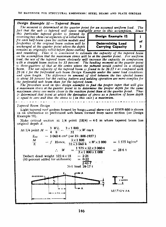
ISI HANDROOK FOR STRUCTURAL ENGINEERS: STEEL BEAMS AND PLATE GlRDERS
Design Exumple 12 - Tapered Beam The moment is determined at the quarter poinl for an assumed uniform load. The
‘act that the web is tapered will cause negligible error in this assum tion. his particular tapered girder is formed by ,eversing two skew-cut segments of a rolledbeam b% each half-beam span the section moduli and )roperties of ihe original beam section will be rnchanged at Ihe quarter point where the depth emains as originally rolled before flame-cutting
m
rnd rewelding. Tkus il is convenienf lo estimate the capacity of Ihe tapered beam In the assumption that Ike maximum slress will be al the quarter point. For uniform oaci, Ihe use of the tapered beam obviously will increase the capacily in comparison r’ith a straight beam section by 33 percent. The bending moment at &he quarter point s three-quarters of that at the centre where the m&nent would control in a straight Beam. The net capacity of the tapered beam is found to be 26.17 t as compared with ?&.I6 t for the perforated web beam Design Example under the same load conditions tnd span length. The difference in amount of sleel between the two special beams s about 10 percent but the culling pattern and welding operalion ale more complex for kt perforated web beam than for Ihe tapered beam.
The procedure used in ljzis design example to find ihs proper taper that will give I maximum stress at the quarter point is fo determine Ihc proper depth for the same naximum stress one melre closer to the reaction point lhan at the quarter point. Thus ‘s determined tkat point al which the derivcrtive of stress as a function of beam depth 1: equal to zero and thus the stress is (in this case) a maximum. -__ _____-_-__-__ -__- _______ -___ ____________-____
I‘apeved Beam Design Light tapered roof girders formed by longLu~ma1 skew-cut of ISMR 600 is shown
1s an alternative to perforated web beam formed fmm same section (see Design Example 11).
Make critical section at l/4 point (l-8/4) = 4.5 m where tapered beam has Jriginal depth d.
3 WL At l/4 point M = & -$- =
3x1800 ----x W cm*t 32
= 3 060.4 ems (see IS: 808-1957 ) M -7 L
= f Hence, 3iz31z.4 XWXlOOO
:. w = 1575X32X30604 3x1800x1 000
Deduct dead weight 122.6~ 18 = 2.21 (10 percent added for stiffeners) = 0.22
2T Nrt load 26.17 t
= 1 575 kg/c.m*
= 28.6 t
SECTION AA

,Ilc (62 C) 28.6 x 18 ? 100 -= = 6 435 cn1.t
.\I iri\ 5.5 in = 6 435 ‘iO.626 5 4 035 cm.t
41.9 (dr -2.08)?
_ 0.2 ,I,” +41.9 riv-+lf,$ ‘;$ ( I >
Required Z at 5.5 from C
to have a stress of 1 575 kg/cm? = 4035x1000 1 57.5
-. = 2 565 cm3
4.32 Rcdllcc to a quadratic equation hy approxim;rting -d, = 0.07
CI’ 0.2 dx?+41.9 dx-171.4 = 2 565 01’ 0.2rExz+41.9d,-2 736 = 0, dx = 52.5 cm
Taper slope _ 60-52.5 = 7.5 in 1.0 m rlC (i;! Q. = 60 +7.5 x 4.5 = 93.75 cm
dc @j ends = 60-7.5 x 4.5 = 26.25 cm
c

fS: HANDBOOK FOR STRUCTURAL ENGINEERS: STEEL BEAAIS AND PLATE GIRDERS
+s a final .check on the stress due to bending, three paints tire chosen near the quarter point
Dcslpn Example I2 3
and direct calqulation made of the stress at these Final Check of of points. Stresses 3
A catcutalion of Ike def?e, lion is made using , Newmark’s numerical brocedure. This is very accurate for a problem of this type and especially useful because of the variable moments of ineuticc. Fov the details of this procedure, reference shonld be made to Section IV. The fovmulce fov eqtcivalent concentvated angle ckange are given on p. 86 and it should be pzoted that at tke cerltve livre of the tapered beam there is a skacrp discontinuity in the iIt/L’t diagram. Tke statement made in the last two serltemes of the Cast pavagraph of 27.1 ( see p. 88) applies to the calculation of the concentvated angle change al the centve line. previously on p. 97 and 98.
Simpler example& of the procedure have been given
_--__-_--_-_-___--_________-------------------~-
End shear capacity:
V = 26.25 (1.2j 945 = 29 800 kg 28.6
or 29.8 t > -- maximum end shear (see 2 p. 146) . . . . . OK.
Check stress dnc to bending at 3 points -near l/4 span. ,
d = 93.75 -‘T- x = 93.75--7*5x (x is in metres); it4 = Mc
2 = 0.2 da = 41.9 d-171.6 (see Sheet 2)
--- x d d’ 0.2 d’ 41.9 d z z’
x’ M 1 i& b MC
x--- 837B 4oKo w13 -270 3 310 18 -- Wl98 -imz e_ 2423 x lo-4 4.5 80.0 36oo 720 2 bl4 3062 20.25 0.249 0.751 2.452 x lo-’
5 66~25 3 li0 634 2 380 2 822 25.0 0.30R 0.692 2.451 x lo-’
6 48.75 2 3RO 476 2 045 2 349 36 0.444 0.556 2.367 x lo-’
This checks maximum stress due to bending at l/4 point. Determine deflection by Newmark Method.
WJLTIPLIER
Location in span 0 116 l/3 4 -
Moment 0 5,‘9 8/9 1 6 435
I - 0.2’22 0527 1 258 500 cm’
M/EZ 0 2.50.5 1.685 1 6 43512 5% E
Cone I$ -. - 26.71 - 20.36 - 13.37 6 435112 x 258 5OO E
SlClpe 3R.i9 2i.o.i 6.69 ( parabolic vgriations )
Deflection 0 5.38 8.09 8.76 264 35O/l2 x 258.5OO E
Centre deflection =. __-~__ 8~76x3*x6435OxlOOx1OOxl 000 = 7.95 cm
12x2050ooox258500

SECTION VIt : TAPERED EE.4Sts
48. DESIGN EXAMPCE OF TAPERED GIRDER
48.1 The tapered beam is particularly suited to uniform loads applied to long spans but may be adapted to concentrated loads somewhat more effectively than the perforated web beam. Design Example 13 is for a tapered girder built up from two flange plates and two skew-cut web plates flame cut from each half span from a single rectangular plate. Design Example 14 compares the design of a three-span continuous beam for the same load conditions that are used in Design Example 13. The total weight of 3 simple spans using tapered beams is found to be about 10 percent less than that of the three-span continuous beam. However, no generalization should be drawn from one comparison.
It is recognized that the ordinary beam theory does not apply precisely to the tapered beam and the stress in the sloping flange will be slightly greater than calculated. However, the tapered slopes are very small, and the stress raising coefficient due to slope may be neglected with small error. For additional information land other design examples utilizing the tapered beam the reader should obtain the previously cited reference from the American Institute of Steel Construction, 101 Park Avenue, New York City.
48.2 The illustrative design esample of tapered girder is shown in the’ following three sheets (see Design Example 13 ).
149
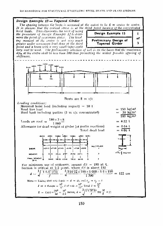
ISI HAEiDB”0K FOR STRL’CTUR.kL ESGISEICRS: STEEL BE.\MS AST) I’L.‘,TB GtRDERS
Loading cmditions:
Bents are 8 m c/c
AMonorail hoist load (including impact) = 10 t Roof live load Roof load including purlms (3 m c/c concentrated)
180x3~8
= 150 kg/m? = 30 kg/m?
180 kg/m”
Loads on roof = ~~- 1 ooT = 4.32 t
Allowance for dead weight of girder (at purlin reactions) = 0.54 t Total dead load =4E
-31 CM, IUL, :.*rt ,.a, Lo&t a.,,
,=I* I={ UuLT’p:‘tR
,,:z&, a 11% J:, ,:I!;, ;I,; :ja; i :
For minimum use of stiffeners, assume d/t = 180 at Q. Section is critical at l/3 point, where d/t is about 150
d = 3 TsEi1 (<r/t) Jo--
__.
.--~~-- --
__._ ~_____
..--- = f
3 i18~32x1OOxlOOOx1~5x15O _ 122 cm J
________~ 1 500

SEC'IION VIt: T.\PERED BE.\IIS
In this sheet, ihe required web depth at fhe end is found lo be 29.3 cm. Since this is rather
Design Example 13 2
small it is arbitrarily increased lo 40 cm, but Finalixing Taper of of fov a IZO-on depth as assumed at Ihe thivd point the d/tw at the centre line would now be
Girder 3
200. To br,i?tg this down to a d/lm of 180 aI ’ Ihe ceMtre it would 1)~ necessary lo have an e?zd deptk of 80 cm. This, however, is judged tip be rather wasteful of matevtal and a 65-cm end depth is finally chosen to make the third paint deptk sligktly less than &&ally assumed. la tkis design, with a sharp break in the moment curve at the third point. there is great flexibility in the choice of centve and end depths because the tlrivd point wtll be critical for maximum stress ovev a -wide range of vavialion in taper.
In a pvelimiuary tvial design, lhe web was made one centimelve thick wilh a 160-cm depth at the cenlre and a 25-cm depth at the end. It was found that this would requive moye steel than the design now being recorded. Furthermore, Ihe small depth near the end would lead to excessive deflectiouz. This will be better understood if one studies the deflection calculation for Design Example 12 where the greatev concentrations of curvature are fairly near the ends. At the bottom of tkis sheet, the stress is ckecked ut the sixth point and centre line. and it is believed that the &al choice of taper and depth has provided a well-balanced design as stiff and as economical of steel as one might desire.
.__--_--_---_____ _________--_______*______________-_.
Web thickness t = zO = 0.8 cm; For V = 22.15 t @ end
Fs __-
= 945 kg/cm2 [see stiffened web as in Table III.1 in 9.3.2(b) of IS: SOO-19561
Try 8-mm web. d (at end) = 22.15
~ = 29.3 cm 8x945
Try 40x 8 at end to 160x 8 at 4. d 160 5 at C = G = 200
Reduce d/r value by changing d to 140 at %, d/t = 175 .\t end, d = 140-3 (140-120) = 80 cm Reduce (I at end to 65 cm to provide more taper (keeping web depth at 4 same
140 cm). Select flange at l/3 point as probable critical location; approximate formula is:
Z = _I,d+% Required Z = 118.32 x 1 000x 100 = 7 888 cmS
1500 \Veb segments will be cut from 65+140 = 205 cm, 205 x0.8 cm plate _1t l/3 point, d = 65+2/3 (140-65) = 115 cm
* z = 7 888 = .-jr: 115+??;!?%; ;. . . &: = 6% = 55.3 cm2 (area of one flange)
Use 40x 1.4 cm Range: rig = 56 cm*
Check d/t of outstanding leg: F4 = 14.3 < 16 . , . . . OK.
Check stresses at 4 locations:
EXD l/6 1 l/3 1 CEXTRE
d 65 Z ( appros )
T 6 1:
115 8200 1oE
fb 1087 1443 1 205
Since l/b = % = 7.5, allowable f, = 1~500 kg/cmz (see 9.2.2.2 of IS: 800-1956)

IS.1 HANDBOOK POk Sfkt,CTtJR-At ENGINEERS: ST&EL BEAMS AN9 PLATE GIRDERS
Vertical intermediate stiffeners aye put in :tarting from the centre line at the maximum )ermitted spacing of I.5 times the depth. depth is consevvatively taken as the greatest in Each paweel.
Thel*i+
Near the bottom of the sheet, the bermissible web sheav stresses b-y Table IV of his handbook worked out err the basisof Table III in IS: 800-1956 ( based on average Eepth in each panel) are compared witk the maximum ,shear slwss in each flatzcl. ____________--_---_-_________-_-_------------------
t---pm- Vertical stiffeners @ 1.5 d (see 20.7.1.1 of IS: 800-1956 )
1~5x140 - 210 cm 1.5 x93.75 = 140 cm
1*5x 122.5 = 184 cm 1.5~82 = 123 cm
1*.5x107.2 = 161 cm 1.5 x71.75 = 107 (or the remaining distance of 82 cm)
Check shear on basis of conservative assumption that d = average depth of web segment between stiffeners and shear stress is maximum in the particular segment.
Check actual fS with allowable F, of TabIe IV (ste p. 182)
Segment ‘4 = f, (averagcj 22~15x1000
= __I_- = 430 kg/cm* 65 x 0.8
d/t (average) = 71.75+65
2x0.8 = 86
Repeat procedure in other segments, and tabulate as follows:
SEGMENT fS d/t FS (AVERAGD) (AVERAGE) (ALLOWABLE)*
A, B 430 86 945 G D 26.5 99 920
(No need to check further panels as shear is reducing and allowable FS Min fron Table IV is 715 kg/cm*)
NOTE -Stiffener size computations, should be made to Design Example 2.
weld design and other details are omtted. Ref.&xc
-___-_-----_-_-_-------~-----_--~~-~~~_~___~_-~
*See Table IIIA of IS: SW-1956 or Table IV-of this handbook.
152
L
SECTION VIII
COMPOSITE BEAM CONSTRUCTION
49. GENERAL
49.1 In composite construction, a reinforced concrete slab is integrally supported by, and attached to steel I-beams. Channel or other type shear connectors are welded to the top flange of the steel beams to bring the concrete slab and the beams into integral action. If a concrete slab is placed on the top of a steel beam without such shear connectors, there will be a certain amount of bond initially but this is apt to be destroyed during the course of time. The shear connectors that unite the slab and the beam in composite construction serve a two-fold purpose (1) tying the slab and beams together and (2) transferring between the slab and the beams the horizontal shear that is developed by composite action. The strength of the composite slab is considerably more than the sum of the strengths of the two components acting separately.
50. DESIGN -EXAMPLE PRINCIPLES
50.1 In .IS : 800-1956 the \ subject of composite beams is discussed in 20.8.2.2. Reference is made in this to IS : 456-1957 Code of Practice for Plain and Reinforced Concrete for General Building Construction (Revised). Thus, the details of design are more a matter of reinforced conttete construction than steel construction’but the steel designer should be aware of the economic possibilities that may be obtained.
50.2 .The use of any particular type of shear connector in composite con- struction should be based on comprehensive tests in structural laboratories. The local distribution of stress around a connector is highly complex and the approach to be made is more one of ultimate strength than elastic ana- lysis. Tests have been made at the University of’Illinois on the channel type shear connector. Another type of shear connector in common use is a single reinforcing bar bent in the form of a spiral spring which is welded at contact points along the entire length of the top flange.
50.3 A section through a~composite beam and concrete is shown in Fig. 35A and the assumed distribution of bearing of stress in the coficrete that is the basis for the Illinois* recommendations of design in Fig. 35B. The use of
WIEST, I. N. AND SIESS, C. T. Design of-Channel Shear Connectors for Composite I-Beam Bridges. Pub&c Roads, Vol 2a, No. 1 ( April 1954).
153

ISf HASUUOOI< FOR STRUCTL’RAL ESGtSEERS: STEEL BE.411S .4SD PL.4TE GIRDERS
35A
ENLARGED SECTION Xx
356 I’rs. 35 ~osrrosrr~ BLOC WIL’II ~11.4h.x~~ SMEAR CoNsECTIONS
composite concrete slab and steel beam construction has been especially common for the short span highway bridge where the concrete slab serves as the road slab but also acts integrally to form the compression flange of the steel beam into a single composite! tee beam unit. 50.4 The top fiangc of the channel shear connector serves to hold the beam and slab together and most of the shear is transferred by pressure near the base of the channel as shown in Fig. 3513. l‘hc spacing of the channel shear connectors follows exactly the same principles used herein for spacing of rivets and intermittent welds in built-up steel girders. The special design problems that pertain to composite beams, as mentioned previously, are those in the reahn of reinforced concrete design.
154
SECTION IX
CONTINUOUS BEAM
51. INTRODUCTION
DESIGN
51.1 The use of continuity in beam construction involves similar problems to those encountered in the design of continuous or ‘ rigid ’ frames as covered in IS1 Handbook for Structural Engineers on Rigid Frame Structures ( under preparation ). When loads are primarily static, consideration should be given to the possible application of plastic design as treated in the ISI Handbook for Structural Engineers on Plastic Theory and ,Its Application in the Design of Steel Structures (under preparation). The economy in continuous construction is open to some question but has found considerable favour in multi-span highway bridges. Use of all-welded construction lends itself especially to the use of continuity much in the same way as does reinforced concrete. Continuous beam construction will usually be somewhat more rigid than simple beam construction and has the advan- tage of supplying more inherent reserve of strength should a local failure result. The analysis is much more complex and design skill and time much greater than needed for simple beam design. If the structure has to adjust to a considerable differential settlement of support, simple beam construc- tion has the advantage of being able to adjust to such settlement -without causing stresses in the members.
For a,more complete discussion of continuity in beam and frame design, reference should be made to ISI Handbook for Structural Engineers on Plastic Theory and Its Application in the Design of Steel Structures ( under preparation) and attention herk will primarily be given to Design Example 14 which will be for the same load and span conditions previously considered in Design Example 13. Thus, a comparison is afforded between the amount of steel required in a continuous beam design and a simple tapered beam design. It is found that the continuous beam requires 10 percent more than the three simple spans. No general conclusion should be drawn but it is obvious that the use of continuity in design does not automatically assure greater economy than simple beam construction.
52. DESIGN EXAMPLE OF CONTINUOUS BEAM
52.1 The illustrative design of continuous beam is shown in the following twelve sheets (see Design Example 14 ).
155

1st IIANDGOOK *OR SI%~UCTURAL ~!Stilh’EBkS: SI’IXL BEAMS AND PLATE C~RBERS
@sign Example 14 - Continuow Beam In the design of a conlinuous beam, some pvelimiuavy c&male shall be made as lo
the distribution of bending moment. The Preliminary anal sis serves as a baAis or the selection of trial member sizes and locations for change in section by addition of cover plates or change in jange thickness. Fov the preli- minary basis, a conslanl moment ofigwlia may be assumed and the tables of influence coefi- cienls for reaclions and moments in Tables V
m
atzd VI (see p. 187 and 188) are especially convenient for pveliminury bending moments. Three span beams have been covered and procedure explained in .4ppendix ;2. In view of the ‘on’ or ‘off’ nature of the monorail hoist loads which form an appreciable part of Ihe lotal load, method of plastic design is nol recommended because of the possibility of fatigue failure. The varialion in loading also requires lhat various moment diagrams be drawn and the design prepared for Ihe over-u11 range of maxi- mum positive or negative moments as determined at any point in the span.
_----------_---------_--------------_____________
Continuous Beam Design
Aitemative to Design Example 13 (Tapered Beam Frame)
Try constant I as basis for preliminary estimate of bending moment. Monorail hoist load 10 t (or none) at l/3 points. (Because of alteration of moment
due to hoist loads, plastic design is not recommended.) Roof pitch provided by variable purlin position
Roof live load = 150 kg/m’ Roof dead load (purlins plus corrugated sheet) = 30 kg/m*
180 kg/m* As bents are at 8 m c/c (taking roof load as uniformly distributed)
180x8 = 1 440 kg/m width Allowance for dead weight of girder at 180 kg/m = 180 kg/m
1620 Use Table VI uf Appendi?r A
Plot moment due to uniform load (dead load + live load) (NOTE - L in tables equals overall span here = 54 III)
Referring to Appendix A, WLz = 1.62~ .54l = 4 723.92, m = n = l/3 MOMENT AT DIST-ANCE MOMENT Y. DOE TO UNIPOKH Loao
FROM LEI’T, 11, (All Spans Loaded), 1n.t (11
l 3.0 + 0’006 7 x (&%l = + 3P7 7 .i + o’W8 9 x 4 733.9 = + 421
IO’8 + 0’006 7 x 4 723.9 = 14.4 + oouo tl x 4 723.9 = + 3:” 18.0 - o’wo 7 x 4 7Y3‘0 i - 5z”j 2.J.; - WtjwJ 7 x 4 723’0 = - 3.*2 "7'0 + U'UW 8 x 1 723.9 = + 1325
-------___________-----_----_-_-------~~--------
*These distances are chosen becayse the coefficients given in Appendix A (sa’p. 184) correspond to thebe onlv.
156

SECTION IX: CoNTINtiOUS Bt?AM DESIGN
1M ‘omemts are calculated for the following hoist load locations :
Dotiln Exrmplo 14 2
I) Centre and end span : Maximum nega- Max Positive C Negative of live moment at support. Bending Moments I2
2) Centre span only: Maximum positive moment in centve span.
3) Both ed spans : AVfaxinttcvz positive moment in end span.
___-_-_--------_____L_-----------------~~---_--~~~
Alaximum Negative dlorrwrt ut Support U Ilue lo Hoist Loads
Load spans AB and BC : Obtain influence coefficients from Appendix A. Interpolate to get coefficients
for M, (MB in this design) with loads at l/3 point. LOAD LOCATION INTERPOLATED ( Distance from INFLUENCE
Left End ) COEFFICIENTS
1;: -0.026 mat -0.031 In+
24 m -0.024 m.t 30 m -0.018 m.t
FzFEXlOX54 = -54m.t P L
Maximum iW, caused by hoist load plus live load plus dead load = -52.5-54 = -106.5 m.t
Maximum Positive Moment in Centre Span:
Load ccntre span BC only _?fm,X (approx) for hoist load = 2 x 10 x 2/3 x l 0.058 x 54 = 41.2 m.t . . . Maximum positive M (Centre span) = t13.25+41.2 = 54.45 met
End Span Moments To calculate hoist load moment in end span with both end spans loaded, use
influence coefficients for R0 and RL (RA) in this design in Table V in Appendix A.
DISTANCE FROM- INTERPOLATED INFLUENCE LEFT END (R,) COEFFICIEN?S
AND RtGHT END ~~----_h__~
(R:) For R, For RA
1; 0.59 0,019 0.24 0.023
Maximum reaction = :0.872x 10 = 8.72
HOIST LOAD LL+DL COMBINED MOMENT MOMENT MOMENT
3.6x 8.72 31.4 31.7 63.1 7.2x8.72-1.2x10 50.8 42.1 92.9
10.8 x 8.72 -4.8 x 10 46.2 31.7 77.9 14.4x8.72--8.4x 10-2.4x 10 17.6 0 17.6
-----_.
l src Sheet 1. tRefer to Table V of Appendix A. :Total R,+R’, which gives 13” in this design for hoist loads in both the end span%
pssihle to calculate RA like thk hecmce of symmetry in load positions. -~
157

ISI HANDRGOK FOR STRUCTURAL :E”ICI>:r,ERS: STEEL REAMS AND PLATE GIRDERS
The moments computed for the beam of niform cross-section are plotted for various lad conditions on this sheet and the maximum zquired section moduli are determined on the qsumprion thal it may be pos,sibI~~ to use a riled beam. Ihis is not necessarily fhr most -oxomical or lowest weight choice as a ix&t-u ham ratio and less web material w&d require fzbivcd to present a desig?l exampk in which a rolled beam with welded cover plates *u.> Il.& in cowtinuuus construcliul:. o?, the basis (I/ the ~tzrsximnrm positive mome?zt 8) the Lentrc .\fiatr ( where a arctiorl modulus of 3 460 cm 3 is irrdicated) a rolled beam pith a section modulus of 3 540 cm3 is chosen. When the continuous beam is stiffened p at the supports and in the end spans there will be a redistribution of moment and ie +oTitive moments in the renlres of all spans will in general decrease slightly while l,e ?lrgative moments over the supports will tend.to increase. Thus, the analysis on be basis of colrslant momrnt of irleut.;a will over-estimate the sectiola modulus require- ‘lenls for positiw ntomrnt zlt the rrvtre .spalp. This should be wlficipakd in the Nreliminary design. ~-___________________-__---_------~-------------
‘reliminary Eslimale Range
Maximum Requived Z (Lateral support of purlin connections is assumed.)
End (positive) : 93 x100x 100 spar,
1 575 = 5 905 cm3
Interior support (negative) 106.5 x 100 x 1 000 : -__- ___. _ 1 575
6 760 ems
Centre span (positive) : 54~45x1OOxlOOO = 3460cmS 1 57s _ _.-
If a rolled beam with flange plate reinforcement is used as a basic section, actua moment at centre span kill be less than the estimated value.
An ISWB 600, 133.7 kg (2 = 3 540 cm3) is chosen as a basic section.
Approximate Z of 2 plates: h =
I = 2Ap 2 =-2 0
Aph=
z= 2’ h
= Aph +I _- .
158

SECTION IX: CONTfhUOUS REAM DESIGN
The additional section modulus requirement for the end span and at the interior support is determined and flange plates are shown at the bottom of this sheet where a check is also~made by the moment of inertia method. The flange plates provide an excess section modulus at tJLe interior support for negative moment and somewkat less than the preliminary estimate fov positive moment in the end span. The cover plates aye extended O-5 m beyond their theoretical cut off points at which they will be asstoned as fully active in tke mope accurate analysis to follow. In view of the possibility of fatigue failuve uudev intermittent load. it is wise to be ‘very cousevvative as to allowabte stresses at cut off points of cover plates in welded plate girders. rlt these loculions, concentrated stvess is developed and it is here that fatigue cracks will occur if they develop anywhere. Also shown on this sheet are the field .&ice locations on the basis that a 14-m length ye- presents the maximum desirable iength for convenient in tvanspnrt. In erection the 9-m segments over the interior columns co& be placed first with temporary shoring underneath to provide stability. Then the interior and exterior 12-m segments may be introduced and-field welds made at locations shown.
_____-_---------------~-----_-_-~---_~_-__~~--_~. Flange Plates Trial Selection
At end span: Z to be added = *5 800-3 540 = 2 260, h=6OOmm 2 260
Ap = -6F = 37.7 cm8 Try 200 x 20 mm plate. .4 = 40 cm*
At support : 3 220 A* = 6’60-3 540 = __
60 60 = 53.7 cm* (excess probably required).
Try 300 x 20 mm plate. A = 60 cm* (excess probably required).
TRIAL LOCATION OF FLANGE PLATES
IWR = 106 198.5 cm” xQc* Plates 2 x 40 x (62)2 zz -.--__
Z = 182k.5
= 76 8OfH cm4 182 998.5 cmr
= 5 770 cm3
IWB = 106 198.5 cm* Plates = 2X60x (62)* m__ 4 = 115320 cm4
221 518.5 cm4
z = 2_21 518 32
= 6 922 cm3 ----------------_-_--______--_____~__~~___~----~-
l Sk?htlY less than the estimated fieure of 5905 cm* is taken.

1st RANDROOK FOR STRUCTURAL ENGINEERS: STEEL BEAMS AND PLATR GtRDERS
Most designers would probably prefer to we the generalized moment distribution procedure in making the final analysis of the structure
-with variable moment of inertia. However,
this would require the availability of tables of
distribution and carry-over factors. In this handbook, the general procedure of
determining reduridant reactions will be used for illustration. The principle is
entremely simple and may be stated simply as follows:
Reactions at B and C (see sketch WL Skeet 6 ) in a three-spax beattr are re-
moved and the deflection at B is then thought of as the sum of the effects of the downward load and the two redundants. This is equated to zero. Under sym-
metrical load conditi0n.s. the reactions at B and C will be identical and a direct
solution for redundant reaction R,, follows. For unsymmetrical load conditions,
two simultaneous equations are obtained with the unknown R, and Re. The
Newmark numerical method is used in the deflection calculations. In Skeet 6, the redundant reactions are shown removed. The deflections as calculated at
B and C are for unit loads at those two points respectively.
lh
Thus, 6 CB represents
e e ec ton at C due to a unit load at B. dfl t’ By the law of reciprocal deflections,
this is equal to 6 BC. In these examples of the Newmark metkod, the original procedure suggested by him has been used in that the conjugate beam idea suggested
in Section IV is not used. Instead, trial slopes are worked out consistent with
the various concentrated angle changes along the beam. Then, in general, trial de$ection is determined that will not come out to zero at the end of the span. In Sheet 6, fov example, the trial deflection is -1.18 at point D. The trial deflected
beam position is rotated into correct position and a linear correction is introduced at points B, C and D. If the deflections were needed at intermediate points, they
could likewise be determined but we are interested here in the deJection only at
support points B and C.
____~~~-------~~~~--~~ ------ -_-_ -_ ____. _-- _____
All the calculations described in the commentary above are worked out with diaKrsms in Sheets 6, 7. 8 and 9.
160

SECTION 1.X: CONTIXUOUS BEAM DESIGN
TO CHECK MOMENTS, RE.iCTlONS AND SHEARS, USE METHODS OF
DEFLECTIONS, UTILIZING NEWMARK’S NUMERICAL PROCEDURE FOR
CALCULATIONS
*These values arc based on average gI in adjacent segments.
M +Thesc values are worked out on the assumption that of varies linearly in each segment [see case
(R) p. 861.
:Assuming maximum deflection at the centre, the figures for trial slope are worked out at different points along the beam. Corrections are made in the further steps and the correct deflections at tht support points are determined.
161

Ftg=43
SHEAR
MCHENT
U/El
CONC 4 t
SLOPE
‘74
Redundant Rc
2-43X3X10
2*43X3X10X3
6 x lOIl9B E
DEFLECTION 8 2*43X9X3X1000
6 x 106191 E


SECTION IX: CONTINUOUS BEAM DESIGN
For dead load and live load, both redundants are considered as simultaneously applied and the redundant yeactions at B and C are found directly by equating the dejection due to these reactions to that due to dead load and live load. Then the reactions at A and D ave found by over-all static equilibrium.
When the hoist load is on one end span, two simultaneous equations are ‘obtained w-hich sum the deflections due lo various effects (applied loads, RB and RC ) and equate the sum to zero. The term representing the downward dejection is put on 1he right side. After solution of the simultaneous equations, RA and RD are found by static equilibrium as before.
After the redundant reaclions ave determined, the shears and bending moments may be calculaled by statics.
Calculate reactions & factors out of all equations
Upward reactions are considered negative. Dead loart+Live load ( symmetrical about B ) By equating the deflection at B: 118’02 RB
= -2.43 x 1~5 x 10.44; RB = R; = -2*43x15x1044~10
10 ____ = -32.27 t
118.02 R,=R, = -2.43 x 18+32.27 = -11.47 t
Hoist load on end s%an onl; 1
62.35 ’ 142.61 x9 T RB+:‘$ Rc = -T (by equating deflections at B) _- __
119Gxl y:$ Re + ‘$2 RC = - --2- (by equating deflections at C)
6,235 R8+5.567 RC = -71.305; 5.567 ReS6.235 Rc = -59.545 Solving RB = -13.63 t, RC = f2.5 t
RA = - (
:x20-$x13.63+;2.5 >
= -8.42 t (by taking moments about D)
RD = -(22.5--8.42-13.63) = -0.45 t
10t lot
A 18 IC 01 5.421 I bbziJ( i.SC 0.451
,_+5.421
l__L55t SNEAR DIAGRAM
+5052n.t
- 25.44n.t @AOMENT MAGR&M
165
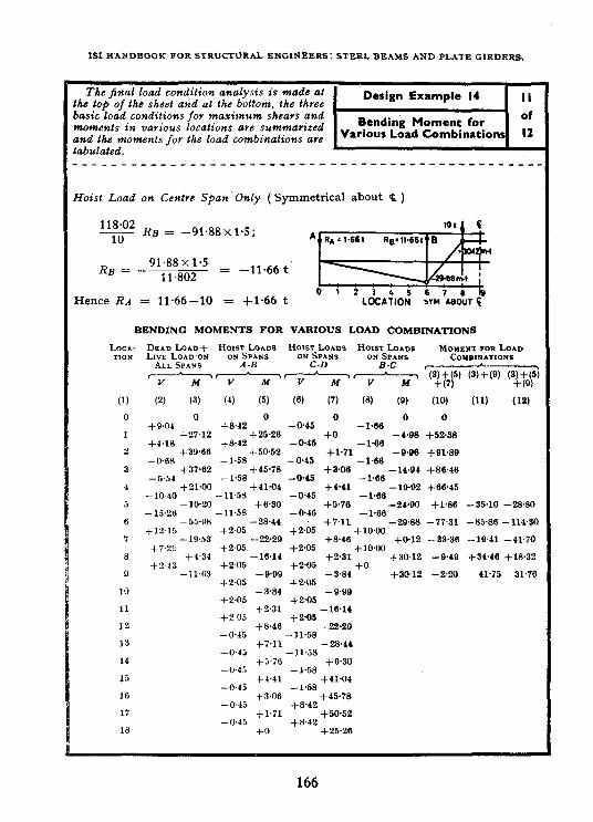
IS1 HANDBOOK FOR STRUCTURAL ENGINEERS: STEEL BEAMS AND PLATE GIRDERS,
The final load condition analysis is made at the top of the sheet and al the bottom, 1he three basic load conditions for maximum shears and moments in various locations are summarized and the moments for Ihe load combinations are raoulalea.
Hoist Load on Cenlre Span Only (Symmetrical about Q )
F RB = -91~88x15;
RB = -91.88x1.5 = Il.802
-11.66 t
Hence RA = 11.66-10 = +1*66 t
AQm!+.$
LOCLTION >V’H *BOUT F
BENDING MOMENTS FOR VARIOUS LOAD COMBINATIONS
Loca- DEAD LOAD+ H”b,“‘S~%;S~~ Ho~n~.oo~~~s H~~Sy~ Moment FOR Lo*n TlOT-4 LIVE LOAD OH COYBINATIONS
ALL SPANS A-B C-D B-C C-A----7
‘F-77 ‘V ,-7--z T-77 WW (3) + (9) (3;yQ 5)
\
(1) (2) (31 (4) (5) (6) (7) (8) (9) (10) w (12) 0 0
+9.04 I +27.12
+4.13 2 +39.66
-0m 3 +37.62
-5.54 4 +21+0
-10.40 5 -10.20
-15.26 6 -5598
t-12-15 7 -19.53
f7.25
6 +4'34 +2.43 9 +11.63
10
11
12
13
14
15
16
17
18
+8.42 ' +25.26
+8.42 +50*52
-1.58 +45.78
-1.58 +41.04
-11.58
-11.58 _;::;
+2.05 -22*29
+2.05 -16.14
+2.05 -Q.QQ
+2.05 -3.84
+2.05 +2.31
f2.05 +8.46
-045 f7.11
-0.45 f5.76
_0"45 f4.41
-0.43
__0.45 +3.06
-0.45 I:'"
-0.45 +o" -0.45 1::: +1.71
:p:
-0.45 -1.66 +3*06 -14.94
-0.45 -1.66 +4.41 -19.92
-0.45 -1.66 +5.76 -2490
-0.45 -I+36 +2.05 +7'11 -29.88
+1ow +8.46 +0.12
+2.05 t10m +n.s1 +30.12
+2.05 +o -3.84
J-2.05 +30.12
-9.99 +*05
-16.14 i-2.05
-22.29 -11.58
-28.44 -11.58
+630 -1.58
+41.04 -1.58
+45.78 +8.42
+50.52 +8.42
+25*26
0
+52*38
+91.89
+8646
+66.45
+1.86
-77.31
-33.36
--949
-2.20
-35.10 -28.80
-85.86 -11430
-19.41 -41.70
+34.46 +18.32
41.75 31.76
166

SECTION IX: CONTINUOUS BEAY DESIGN
.The moments tabulated on Sheet 11 are plotted on this Sheet along with the moment capasity fov the cover plates originally selected. I# is noted that the capacity over the interior support fails a little short but this should be acceptable since the actual moment due to the distribution of load at the support point will be considerably less than indicated.
The positive moment in the end span is more imfiortant and the jange plates aye increused 25 mm in width and 0.5 m in length which provides adequate moment capacity.
Negative overstress at B not serious because of rounding off moments over support.
Eow required 2 for positive moment at end spans = 91~9xlOOxlOOO
1575
= 5 835 cm’
Change-over plates to 210 x 20 mm and extend 0.5 m more towards the centre span.
A 3 42 cm*
I of iSWR 600 = 106 198.5 cm*
1 of plates = 2_“_42 x (62)” 186 922.5 ___ = 80724 cm’Z=-------==5841cma
4 , 32
Total I = 1g6 922.5 cm*
No new analysis needed; change of I in end spans has little effect on distribution of moment.
Shear. capacity of beam is more than ample. For other details of design, see Design Examnle 1.
167

As in the Original Standard, this Page is Intentionally Left Blank

TABLES
TABLE I SELECTION OF BEAMS AND CHANNELS USED AS
FLEXURAL MEMBERS BASED ON SECTION MODULI
( Clause 4.1 )
MODULUS OF SECTION
(Zx,)
(1)
cm3
3 854.2 3 540.0 3 060.4
2 723.9 2 428.9 2 359.8
2 091.6 1 933.2 1 808.7
1 558.1 1 543.2 1 350.7
1 223.8 1171.3 1 022.9
965.3 887.0 778.9
.x4.1 7sJ.9 6995
654.8 607.7 -573.6
-571.9 532.1 488.9
475.4 424.2 410.5
_I__
_-
I
DESIGNATION
(2)
.-
(3) (4)
kg kg x lOa
*ISWB 600 145.1 66.9 *ISWB 600 133.7 63.5 *ISMB 600 122.6 68.0
*ISWB 550 112.5 54.6 *ISLB 600 99.5 59.5
ISMB 550 103.7 58.2
*ISWB 500 95.2 46.8 *ISLB 550 86.3 51.5 ISMB 500 86.9 48.2
*ISWB 450 79.4 *ISLB 500 75.0 *ISMB 450 72.4
39.1 43.5 40.0
*ISLB 450 65,3 36.8 ISWB 400 66.7 32.5
*ISMB 400 61.6 33.6
*ISLB 400 56.9 30.2 ISWB 350 56.9 26.5
‘ISMB 350 52.4 26.8
KISMC 400 49.4 32.5 ISLB 350 49.5 24.5
*IsLc 400 45.7 30.2
ISWB 300 48.1 21.0 *ISLB 325 43.1 21.5 ISMB 300 44.2 21.3
*ISMC 350 42.1 26.8 *IsLc 350 38.8 24.5 *ISLB 300 37.7 19.0
ISWB 250 40.9 15.8 *ISMC 300 35.8 21.5 ISMB 250 37.3 16.3
WEIGHT PER SHEAR CARRYING METRE CAPACITY
(WI (9
169
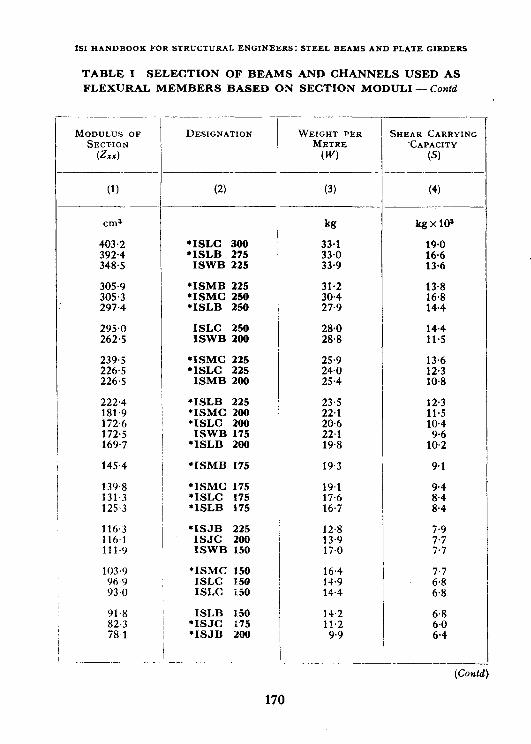
ISIWANDBOOKFORSTRUCTURALENGINEERS:STEELBEAMSANDPLAIEGIRDERS
TABLE I SELECTION OF BEAMS AAID CHANNELS USED AS
FLEXURAL MEMBERS BASED ON SECTION MODULI - Contd
MODULUS OF SECTION
(Zzx)
(1)
CIIlS kg kgxl0’
403.2 l IsLc 300 33.1 19.0 392.4 l ISLB 275 33.0 16.6 348.5 ISWB 225 33.9 13,6
305.9 *ISMB 225 31.2 305.3 *ISMC 250 30.4 297.4 *ISLB 250 27,9
295.0 ISLC 250 28.0 262.5 ISWB 200 28.8
13.8 16.8 14.4
14.4 11.5
239.5 *ISMC 225 25.9 13.6 226.5 *ISLC 225 24.0 12.3 226.5 ISMB 200 25.4 10.8
222.4 *ISLB 225 181.9 ‘ISMC 200 172.6 *ISLC 200 172.5 ISWB 175 169.7 ‘ISLB 200
23.5 22.1 20.6 22.1 19.8
12.3 11.5 10.4
lit4
145.4 *ISMB 175 19.3 9.1
139.8 *ISMC 175 19.1 131.3 *IsLc 175 17.6 125.3 *ISLB 175 16.7
9.4
;:::
116.3 *ISJB 225 12.8 116~1 ISJC 200 13.9 111.9 ISWB 150 17.0
;:;
7.7
103.9 *ISMC 150 16.4 96.Y ISLC 150 14.9 93.0 ISLC 1.50 14.4
7.7
2:;
91.8 ISLB X50 14.2 6.8 82.3 *ISJC 175 11.2 6.0 78.1 *ISJB 200 9.9 6.4
DESIGNATION
(2)
-
WEIGHT PER SHEAR CARRYING METRE CAPACITY
(W) (S)
(3)
-
(4)
(Contd)
170

TABLES
TABLE I SELECTION OF BEAMS AND CHANNELS USED AS
FLEXURAL MEMBERS BASED ON SECTION MODULI --‘ConM
MODULUS OF SECTION
G= )
\VRI(;HT PER hmut CARRYIW METRE CAPaCITY
(W 6)
-_I-
(1) (2) (3) (4)
cm8 kg
13.0 12.7 11.9
kg x 10’
71.8 ISMB 125 66.6 ISMC 125 65.1 ISLB 125
62.8 ISJC 150 57.1 ISLC 125 54.8 *ISJB 175
1;.‘, 8.1
::; 5.2
5.1 5.2 5.3
51.5 ISMB 100 43.2 *ISJC 125 42.9 *ISJB 150
11.5
::;
3.8 3.5 4.3
37.3 ISMC 100 9.2 4.4 33.6 ISLB 100 8.0 3.8 32.9 ISLC 100 7.9 3.8
24.8 *ISJC 100 20.3 ISMC 75 19.4 ISLB 75
5.8
66:: ::; 2.6
17.6 *IsLc 75 5.7 2.6
Norb - l;or using this table, proceed as follo\\s:
a) I,ocate the required modulus of section ( ZXX ) in co1 1. Where the ex- act .Zx* is nut available, select the immediate next higher value of ZZ,.
b) l’he section opposite this value in co1 2 and all sections above it satisfv the requirements with regard to Zxx.
2
If the section opposite this value bears an asterisk, it is the highest beam in the series to serve the requirement. Otherwise, higher up and choose the first section bearing the asterisk(*).
proceed
If conditions require that the section shall not exceed a certain depth, proceed up the column until the required depth is reached. Check up to-see that no lighter beam of the same depth appears higher up. (‘heck uli tlie selected section for web capacity in shear. In cases of eccentric loading ui- any other special conditions of loading, exercise ncccssary check. IL is aasumcd iu this table that compression flanges of the section have adequate lateral support.
171

1S1HAKDBOOKFOR sTRUCTURALENGINEERS:STEELB~AMSAND PLATEGIROEPS
TABLE II PERMISSIBLE BENDING STRESS IN COMPRESSION ON UNIFORM CROSS-SECTION
(Metric Units,
( Claup ---
W d/t, d/l, FOR d/l, FOR d/t, FOR dl'r FOR =I0 =15 EVERY =20 EVERY -25 EVERY =30 EVERY
\'ALUE VALUE VALUE VALUE
o;fFs OF d,ltf OF d/tf IN- IN-
o;Nd_lls
CREAS- CREAS- CREAS- CREAS-
ED BY EDBY EDBY ED BY 1, SUB- 1, SUB- 1, SUB- 1, SUB- TRACT TRACT TRACT TRACT
...~~ -__ - ~_
20 1 575 1 575 - 1 575 - 1575 - 1575 -
:: 1 1 575 575 1575 1575 -- - 1 1 575 575 - - 1 1 575 575 - - 1575 1575 - - 23 1 575 1 575 - 1 575 - 1 575 1 575
;z 1 1 575 575 1 1575 575 - - 1575 1 575 - - 1 1 575 575 13.4 )_4 1 1 573 508 20-7 21.7
i; 1 1 575 575 1 1 575 575 -- 1 1 57s 575 -7-6 1 1 575 537 25.2 31.9 1449 1 378 22.5 21.4 2x 1 575 1575 - 1 575 22.6 1 462 31.7 1 303 20.1 29 1 575 1 575 30 1 575 1 575 Y-6
1 57.5 38.6 1 382 29.7 1 233 20.4 1 527 46.2 1 296 31.9 11.51 19.0
31 1 s75 1 575 30.2 1 424 43.8 1 206 27.9 1066 17.5 32 1 575 1 575 31.6 1 417 44.2 1 196 27.4 1 059 19.7
;: 1 1 575 575 1 1 57s 575 48.0 39.4 1335 1 378 43.5 42.7 1 1 160 121 27.4 27.4 1022 984 18.9 18.0 35 1 575 1 1 575 57.4 1 288 41.6 1 080 26.0 950 18.2 36 1 57s 37 1 575
1 1 575 /
/ i 67.4 1 238 40.5 1 036 25.7 907 17.3
1 547 69.2 1 201 39.6 1003 25.6 875 16.5 38 1 575 1 495 66.6 1 161 38.7 968 24.4 846 16.8
2 1 1 575 575 1 14lfi 466 I 66.0 64.0 1136 1090 38.1 36.9 945 906 24.4 23.9 823 786 17.0 16.1 41 1575 1 370 62.0 1 060 36.2 879 22.9 764 16-3 42 1 575 1 3.55 61.8 1046 35.9 866 23.1 751 15.8 43 1 57s 1313 60.3 1011 35.0 836 22.7 723 15.1 44 1 575 1 289 59.0 994 34.6 821 22.0 711 15.4 :z 1 1 575 575 1 1 242, 217 57.3 56.5 9.55 934 33.4 32.9 788 770 21.6 21.4 680 663 14.7 14.5
47 1 575 1 187 54.9 912 32.2 751 20.6 648 14.8 48 1 575 1 158 53.9 888 31.6 730 20.4 628 14.2 49 1 575 1 154 54.1 884 31.5 726 20.6 623 13.9 50 1575 i 1118 1 52.2 857 30.7 704 19.7 605 13.9
I _.._.____ L_-__---_-___--_--__-_--.
172

TABLES
THE EXTREME FIBRES OF BEAMS WITH EQUAL FLANGES AND ( STEEL CONFORMING TO IS : 226-1958 )
Wcm* 1
6.3 I
d/f =35
L 57.5 I 57s I 575 I 575 1469 1 399 1 336 1 271 1 203 1131 1 056
978 961 928 a94 858 821 792 762 738 706 683 672 647 634 608 589 574 557 553 535
- - -
FOR dl’r FOR Wf FOR d/t, FOR di’r ;VERY =40 E SVERY =45 <VERY =50 hv~Ry =lOO JALUE \ IALUE Y’ALUE rALUE
)F d/t, C IN-
)P d/t, IN-
)F d/Q IN-
)F d/t, IN-
:RE.IS- c :REAS- ?Rl?hS- :REAS-
ED BY ?D “y
; ED BY ED BY
) SUB- , SUB- , SUB- D, SUB-
IRhCT rRhCT TRACT TRACT
W
- 1 575 - 1 57s 1 575 1 57s - 1 575 - 1 575 1 575 T4 1 558 - 1 575 - 1 575 l-2 1 569 28.4 1427
12 1 536 12.1 1 475 1391 11.2 1 335 ::::
1 435 27.9 1 295 1 298 27.0 1 163
15.0 1 324 9.2 1 278 8.6 1 235 27.4 1 098 14-4 1 264 10.3 1 212 8.2 1 171 27.6 1 033 13.8 1 202 11.3 1 145 7.9 1106 27.5 968 14.5 1 130 10.7 1 076 7.5 1039 27.3 902 14.9 1 0.56 10.1 1006 7.0 970 26.8 836 13.9 ,986 939 7.7 900 26.0 769 12.9 ~914 ;:; 864 7.2 828 25.0 702 12.6 897 9.7 848 813 25.6 684 13.3 862 9.3 815 ;:; 780 25.7 652 12.7 830 9.0 785 7.6 747 25.5 619
:22:: 797 9.6 749 7.2 713 25.3 586 758 9.1 712 678 24.9 553
13.0 727 8.7 684 t:; 650 24.8 527 12.4 700 9.2 6.54 6.3 623 24.5 500 11.1 682
;:; 638 6.9 603 24.4 481
11.3 649 606 6.6 574 23.9 4.54 11.6 625 8.1 584 6.3 553 23.7 434 11.3 615
593 ;:: 572 540 23.8 422
10.9 552 ;:; 518 23.4 402 11.2 578 8.1 538 6.3
‘% 23.5 389
11.3 551 513 6.1 22.9 368 10.3 538 3:; 49&i 5.9 468 22.7 355 9.9 524
;:: 482 5.7 454 22.5 342
10.1 507 z::
6.0 439 22.2 328 10.5 501 7.3 6.0 434 22.3 322 t”9 10.1 485 7.6 447 5.7 419 22.0 309 50
- -
NOTE 2 - It may be observed that there is a little difference between the values given in this table and those given in Table HA of IS: MO-1956. The values given in this table have been obtained directly from the formula given in E-l.1 of Appendix E in IS: SCKJ-1986 and may be taken as more accurate.
;7 22 23 24 25 26
zi 29
z
:: 34 35
:f 38
ZJ
t : 43 44
ii 47
173
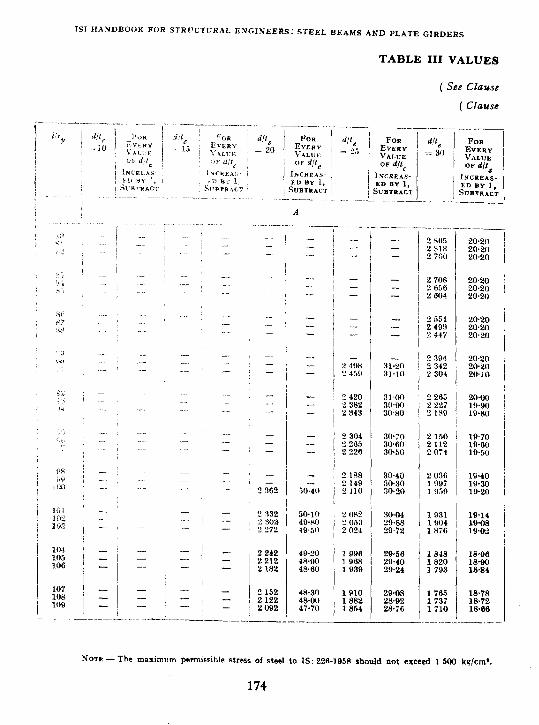

OF ‘A’ AND ‘B’
P-2.1.3 of IS: 800-1956 )
6.3 )
-_-.
dPI 3 35
41, w, = loo r*
‘I’)# dl’, = 45
B
-. -.. 2618 23.40 eda4 23.32 "512 23.24
2499 2462 2447 2410 2396 2358
zwo 23.16 2344 2 307 2 Jon 23.08 2 292 2265 2356 23.00 2240 2 204
2 403 22.92 2189 2 IV2 2251 z2+i4 2 137 2100 "109 22.76 2085 2048
2 147 22.68 2034 1987 2095 22 60 1982 1945 2058 22.54 1945 1908
2021 22.48 1908 i 004 22.42 1872 1947 22.3R I a85
1871
: ii:
1910 I a72 1835
22.90 1798 22.24 1761 22.18 1724
:;ii 16e.e
1799 1761 1724
: %I 1642
1614
: EI
1531 1m 147t
22.12 22.06 22Qo
22m 22.00 22m
22.00
;;:g
ES 22Qo
1888 1651 1614
1649 x 612 1675
1586
: %
1504 1.476 1449
::z 1see
1648
: :t:
1465
:tz
:iE i 328
--
s”‘: a2
a6
i;:
89
E
:: 94
zi 97
tit 100
101 102 103
104
::
g
i 3.74 i3.72 :3.70
’
/ j j
I
I
13.28 ?3-12 12.96
L OIIR 1 WI2 L 025
WI2 R.QH 9.04
I! 052 i : 2.80 2014 i 12.64 197ti X2.48
1WR 1851 I914
WlO
i::;
l+2R 9.34 0.40
1 H3A I “,oo ? 77a 0.38 I tina 12w 1748 0.36 I iHI I ‘24.M 1720 9.34
1 i's3 l‘?.OR 1693 Cl.32 Li2R 12.10 ltw3 9.30 1 O!?LI 12.12 163.3 Q.28
,871 1644 101R
--. I_ 12.14 1610 9.26 12.16 1583 9.24 12.18 1556 9.22
t&j:! s.fS
0.54 6.72 0 I7 W38 wo 0.81
942 6.00
ii% 6.56 6.52
831 ; 6.48 7Y3 0.44 746 i 6.40
729 / 6-42 701 ! 6.44 674 ; 6.46
: ? ;-:
/ !
: I ! ! / 1
1 1
I ’ I :
840 64 619 592 i
6.50 6.52
504 i 6-54
iiz 6.56 6.58
175
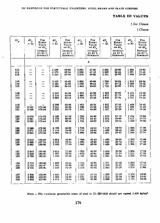
1SlHANDBOOK FOR STRUCTURAL ENGINEERS: STEELBEAMS~AND PLATEGIRDERS
TABLE III VALUE’5
( See Clause
( Chbse
___-
IbY dPe FUII d/f, FOR FOR FOR F0It
= 10 E;,3; =15 EVERY
We dfte 0,
VALUE = 20 t:z = 25 ",zz 3 80 K:::: OP d/t, OF d/t, OF dfte OF d/t, OF dfts
INC*E*S- INCREAS- INCREAS- INcnEAs- INCREAS- EDBYl, ED sul, ED n-1, ED SUl, EDBYl, SUillYtACT SIJBTRACT SUBTRACT 1 Sqsralcl SUBTRACT
-__
I A
______~___
::': - - - 1 2406 2170 86%0 86.34 2062 2030 47.40 47.16 1803 1825 28%0 28.48 1661 1682 lA%o 18.58 112 - - 2 445 85%8 2016 46.02 1781 28.36 1630 1856
118 - - z;z kZ:t: 1002 46%8 1750 28.24 1618 18.64
::: z - - i368 84.50 1060 1046 46.44 46.20 1737 1715 gz . ' 1506 1575 18.52 l&56
::: - - 1023 45.06 1554 118 z I
2 2318 343 54.04 83.58 1603 1671 i7%8 27.76 18.48 18G6 2292 83.12 1640 27.64 :z: ltw4
110 2286 82.66 1853 45.24 21.52 1480 lR.42
:z 2241 2220 82.20 81.76 1830 1811 45.06 44.80
:s
1587 Z'Z . 1451 1468 lA.40 18.30
:z zz 175.72 174.58 "2:z !Z 1703 1774 44.60 4440 1570 1652 27.12 26.08 1434 1417 18.20
124 3025 173.44 2157 so.44 1755 44.20 1534 26.84 1400 :z;
:z tzt 172.30 171.16 zt ’ KG 1736 1718 44.00 43%0 1516 1400 26.70 26.56 1383 1366 Ii90 17%0 127 2045 170.02 2005 70.12 1600 43%0 1481 26.42 1340 17.70
128 ;x:: 168%8 2074 7868 l&30 43.40 1463 26.28 123 167.74 2053 78.24 1662 43.90 1446 26.14 130 2865 166%0 2032 77.m 1643 43.00 1 428 26.00
131 2843 165%0 2OI5 7736
132 Kz 164WJ 1097 133 163.60 19RO ;z .
134 2775 162%0 1062 70-04 1582 42.m 1471 25.52 1243 li.16
-
Nom-The maximum permissible stress of steel to IS: 226-1058 should not excead 1 500 kgfcm*.
176

TABLES
OF ‘A’ AND ‘IS’- Contd
E-2.1.3 of IS : 800-1956 )
6.3 )
d/t, FOR
= 35 EVERY VALUE OP d/t,
INCREAS. ED BY 1, SueTRAcT
1539 1568 1516
1 525 1504 14R2
1401 1440 1419
13QI 137R 1360
1343 1326 1310
12!)4 1277 l&i0
1244 122R 1211
119R 11&L 1171
1157 1144 1131
1117 1104 1090
12.20 12.16 12.12
12.08 12+4 12w
11.96 lL.!)Z lL+J8
LLG+l ll+N 11.72
11.40 11.32 11.24
11.16 L L.OA 11.00
11.06 11.12 11.18
11.24 11.30 11.36
Il.42 11.48 11.34
1528 1507 14.s
1465 1444 1422
1401 1380 1359
1338 1317 1301
1285 1209 1253
1236 1220 1204
11&i 1172 1150
1142 1129 1115
1101 1088 1074
:Ei 1033
9.20 9.18 9.16
9.14 9.12 9.10
R.08 9m 9.04
9.02 9.00 9.04
9.08 9.12 9.16
9.20 9.24 9.28
9.32 9.36 w40
9-26 9-18 9.04
8.92 &80 &68
8.56 6.44 8.32
: % 1449
1419 1398 1377
1356 1335 1314
1293 1272 1256
1239 1223 1207
1190 1174 1158
1142 1125 1109
1096 1083 1070
1057 1044 1030
1017 1004 991
6.60 6.56 0.52
8.48 6.44 6.46
6.36 6.32 w?u
6.24 6-20 6.22
6.24 6.26 6.28
6.36 6.32 6.34
6.36 6..38 640
6.36 6.32 6.28
6.24 6.20 6.16
6.12 6.03 6.04
1449 1428 1407
1387 1366 1345
1324 1303 1283
1262 1241 1225
: E 1175
1159 1143 1126
1110 1093 1077
1064 1051 1033
1 025 lOL2 1000
9u7 974 961
22.00 El%l 21.96
21.94 2L.92 21.90
21+x3 21.86 21.34
21%
%~
21.60 21.50 21.40
21.30 21-20 21.10
21.00 20.90 20.80
2::; 20.86
20.88
E.E
20.94 20-96 2o+k3
1339 1318 1298
1277 1256 1236
1215 1194 1173
1153 1 132 1116
1100 1084 1068
1052 1037 1021
1005 989 973
960 947 934
921
iti
iii 856
d/t,
=.oD
B
1301 1280 1259
1239 1218 1197
1176 1155 1 135
1114 1093 1077
1061 1045 1 029
1012 996 980
964 946 932
n19 906 893
880 868 a55
$42 829 P16
110 111 112
::: 115
::: 116
:z 121
122 123 124
:z 127
ii-i 130
134 135 136
177

1SI HANDBOOK FOR STRUCTURAL ENGINEERS: STEEL BEAMS AND PLATE GIRDERS
TABLE III VALUES
( See Claws
( Clause
Noti -The maximum permissible stress of steel to IS: 9361958 rhould not exceed 1600 kg/cm*.
178
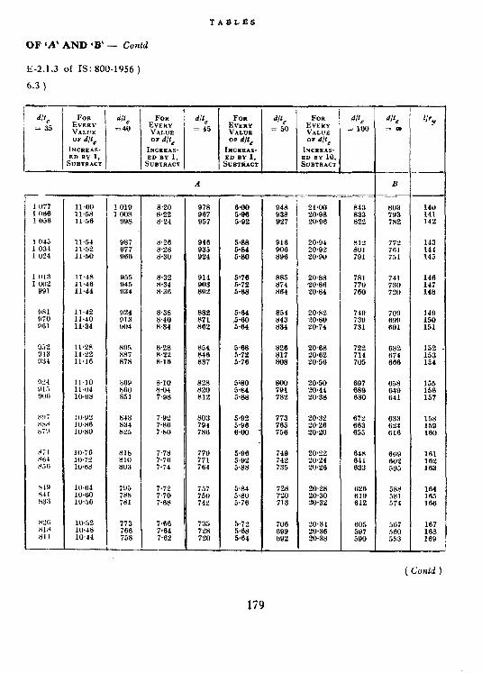
TABLES
OF ‘A.’ AND ‘B’ - Conld
E-2.1.3 of IS: 800-1856 )
6.3 )
11.60 11.58 ll"56
11.54 11.52 11.50
11.48 11.46 11.44
11.42 Il.40 11.34
11%8 11% 11.16
11.10 11.04 IO+8
IO.82 IO.86 lW80
lO.iG 10.72 1068
10.84 10.60 105G
10.82 lU.48 1044
987 977 068
955 945 934
924 013 904
869 860 851
843 834 825
818 810 803
7Y5 7% 781
773 766 758
8.20 8.22 8.24
8.26 8.28 8.30
8.32 8.34 8.36
8.38 8.40 8.34
828 w!! 8.16
a.10 8.04 7.98
7.92 7.86 7wJ
7.78 7.76 7.74
7.72 7.70 7.88
7.66 7.64 7.62
882 871 862
a54 846 a37
82X 820 812
ix: 736
77Y 771 764
i57
;;!: I
735 720 720
GQO 5.96 5.92
5T76 572 5.88
5.64 5.60 5.64
5.68 5.72 5.76
5%0 5.84 5m
5.92 5.06 6.00
5.96 5.92 5.88
5.84 5& 5.7G
5.72 5.68 5.64
948 Y38 027
916 WIG SYG
AR.5 .!I74 864
854 n43 834
826 817 808
800 791 782
773
E
749 742 735
iec, 7'10 713
706 699 G92
21m ‘uksR 20.96
20.94 20.92 2ow
2O+B %W86 20.84
20.X2 20.8O 20.74
20%8 20.82 PO.56
2050 2044 20.38
20.32 2O26 2WO
‘2"."% 20.24 2026
20~2.3 2@30 20.32
20.34 20.36 20.38
843 853 822
812 301 791
781 770 780
697 088 680
652 G85 655
648 641 893
628 Gl!J 612
605 597 590
-
B
803 793 782
77f 761 731
741 730 720
709 GYY 891
682 874 066
658
z:':
653 624 GtG
588 581 574
567 560 553
140 141 142
143 144 145
146 147 148
149 150 151
g
155 156 157
158 159 180
161 162 163
164 165 166
167 168 169
( Cod )
179

ISI HANDBOOK FOR STRUCTURAL ENGINEERS: STEEL BEAMS AND PLATE GIRDERS
dlfe = 10
170 171 172
173 174 175
176 177 178
li0 180 161
132 183 184
l<Ki lb8 187
1% 1XY 190
101 l’J1 1W
lY4 195 196
lY7 1 !I8
200
d/t = 1’5
! 142 ! 12’3 ! 117
! 104 ? oY2 ? 079
I066 e 054 z 041
2 020 2 016 2005
1 nor 1082 1971
1960 194Y 1 038
1 Y26 1915 1 ‘904
1804 1 an4 1 Ui4
1 864 1 &bP 1 842
1 s33 1 x2; 1815
1305
131.60 130.92 13024
12Y.56 lWt(8 lW2Y
127.3% 126.81 126.16
125.43 124.RO 124%l
123.60 123~00 lU.40
1 IH.3lj 117.w lli.48
lI7.04 Ilwno llti.lti
llzl.iZ 115.28 114.84
114.40
14.84 1475 1466
1456 1447 14315
1420 1420 1410
1 401 1 308 1 3x4
1 3i6 I 367 1 .,50
1 3.i I 1343 1 33.;
1 326 I 318 1 310
1 302 1 “Il.5 1 %i
1 2.x 1 248 1 241
1 233
FOR EV!LRY
0,
VALUE = 20
OP d/f,
INCREA-+
61.92 61.04 6076
59.60 5Y.30 5YW
&+70 58.40 58.10
.iiWl 57.X 57.20
56w >ti..>” 56.lU
.TG.x4 ;,.?..i,B 55.16
54.a 54.48 54.14
53.80
1168 1161 II53
1 I46 1 13n 1 130
11‘12 1114 1 107
1 (I!)0 1 OYl 1 084
I 078 1 Oil 1 064
1 OS7 1031 1 0’14
loo0 YY4 Y6U
Yn:! Y76 !)iO
964
TABLE III VALUES
( See Clause
( Clause
FOR EVERY VAI.UE OF d/te
dlte = 30
INCREAS. ED BY 1,
SuBTRacT I ,
991 984 977
YiO YH3 Y56
040 Y42 035
YW 011 915
880 883 876
670 863 857
837 032 I)26
821 UlK 811
806
22.40 -22.3’1 22.24
22.16 22.08 22.W
21.Y2 sl.a4 21.76
21.68 21.60 21.34
21.08 2O.N 20.56
20.30 20.04 19.78
IO.52 1926 lQ.Ml
llJ.14 19~28 lY.42
18.56 10.70 19.84
19% 20.12 20~26
2040
&47Y 87% 866
83’3 8YY 826
320 HI3 808
R03 798 793
ii2 567 76”
730 733 727
721 716 710
704
15.20 15.14 15-OU
15W 14w 14+llJ
14.34 14.78 14.72
14.66 14-30 14.66
14.76 L4.a4 14~92
15~00 1.X3 13.16
15.24 15.32 15.40
l&lH 14.Y6 14.74
14.52 14.30 14.08
138ti 13.64 1342
13.20
Nors - The maximum pemissible stress of steel % IS: 226-10~8 should not exceed 1 500 k&m’.
180

OF ‘A’ AND ‘B’- Cmtd
E-2.1.3 of IS: 800-1956 )
6.3 )
A B
808 10.40 751 7+mJ 713 5.00 as5 20~~0 583 540 707
170 1030 745 7.60 707 5.64 2lJ.34 577
700 540 171
lW32 73lJ 7.00 701 5.68 g;
W"8 571 BSI 172
784 10% 7Y3 7.60 005 1.72 6UO 20..22 .x5 %
.m 178 10.24 10.20 ;;i 7.60 7.00 682 080 5.76 5-80 6UO txJ4 2Wl6 WIU 559 553 522 174
.xti 17.5
765 10.10 714 7.60 676 5.84 647 20.04 547 511 ::I IO.12 lWJ8 % 7.60 7.60 070 654 5.68 5.92 641 635 lO%w 19~02 Xl 535
z ::!: 178
E _1000 1004 690 606 7.60 5.96
EZ
628 622 19.80 19.80
Ei
658 652 520 523 403 179 487
784 lOTJO 684 647 617 19.78 518 482 :z
729 10~00 679 7.48 642 b-92 012 513 477 724 lO+O 674 OS6
:"g:g 508
718 472 :D
1000 668 E * 631
EE z3 19.72 509 407 184
712 l@OO 662 77:;: 6sZ6 5.80 .i97 :i% 498 462 185 707 low isi 621 6.76 502 404 456 186 702 10~00 7.18 616 5.72 587 19WJ 480 451 187
606 lum 046 7.12 iA! 5.68 582 19.64 484
3
446
1000 1OW 040 035 7.08 7.00 609 5+4 wnl 577 572 19.82 10~00 470 441 474 436 % 190
i?s 9.94 0'88 9.82 631 626 622 ~~ 7.12 505 501 586 XX 5-52 10.56 19.52 :z 432 101 192 5.48
568 663 659 1046 481 2: 198
666 9.70 017 7.16 "5;;
G.44 554 10.44 662
457 410 194 %70 613 7.20
657 9.64 609 7.24 572 z':: . 550 19.40 453 415 105 546 19.36 449 411 196
652 0.58 804 7% 608 5.82 541 BP7
19.32 445 407 107 9%
643 0.40 E 7.32 563 5.28 537 lO?Ju 440
7.36 559 5.24 532 lo.24 486 %i :ii
638 940 591 7.40 554 5.20 528 19~20 432 394 200
181
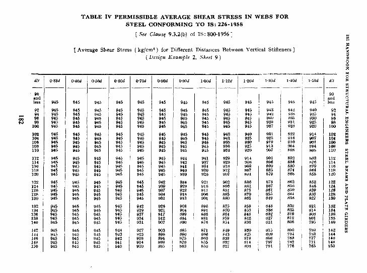
90 and less
102 104
:8: 110
112 114 116 118 120
122 124
:E 130
132 134 136 138 140
142 144 146 148 150
omd 040d
d45 945 945 045 945 945 945 945 945 945 045 945 945
945 845 945 945 945 945 945 945 945 945 943 942 940 845 945 845 945 945 945 945 945 945 945 91'2 938 935 945 945 945 645 945 945 945 945 945 945 940 935 9.W 845 045 945 945 945 045 945 945 945 945 930 931 825 845 945 945 945 945 945 945 945 945 945 937 928 920
:b"; 045 945 945
945 n45 945 945 948
945 945 945 945 945
945
t 45 45 945 945
945 $44.: 645 045 Q45
945 945 945 945 945
945 945
E 945
945 845 945 945 945
945 945 945 Q45 945
945 045 945 945 045
945 945
E 945
945 945 845 845 945
945 946 945 945 945
945 945 946 945 945
945 045 945 945 945
945 945 Q45 045 945
943 941
E 934
940 931 935 925 930 919 925 913 920 907
922 916 910
zz
914
z: 884 888
945 945 945
:z
945 945 945 944 945 945 945 943 945 945 945 841 945 945 945 940 945 945 945 939
941 937 934
g;
928 923 918 912 YO7
914 908 903 897 891
BOl 896
:8"5' 878
a92 886 880 874 868
882 876
% 858
945 945 945
zz
945 942 934 921 945 939 929 P16 945 937 923 911 945 934 918 906 945 n31 913 PO1
;:: 801 885 880
886 881 875 870 865
8i3 867
xz 849
2 ::6 a.50 844 838
852 122 846 124 839 126 833 128 827 130
945 Y45 945 943 945
942 939 937 934 931
926 921 917
E;
% 899 894 890
8n6 875 850 843 832 821 132 HBl 870 853 838 825 814 134 886 864 848 832 819 808 136 881 859 842 827 812 801 138 8i6 854 836 821 806 795 140
RJR Y45 045 945 945
925 !I23 Y18 914 910
E 894 889 885
885 880 875 870 869
848 843 838 832 825
:‘E 819 814 R08
815 809 SO3
ET
8O@ 794 788 782 776
789 ;;; 571 565
TABLE IV PERMISSIBLE AVERAGE SHEAR STRESS IN WEBS FOR
STEEL CONFORMING TO IS: 226-1958
[See Clause 9.3.2(b) of IS: 800-1956 ]
[ Averige Shear Stress (kg/cm2 j for Different Distances Between Vertical Stiffeners]
(&sign Example 2, Sheet 9 )
0.5Od 04Od omd O.&Od O.BOd l.OOd l.lOd 1.20d
-r.
1.30d
--
_
_.- 1.40d l.jOd d/f
90 and less
102 104 106 108 110
112 114 116 118 120
142
1:: 146 150

162 164 166
::
162
:z
%
172 174
:;t 180
182
g
199
192 194 196
%?I
& w
z
z!
212 214
2:: 229
iii
z 230
ZE
z
E E 945
845 945 945
iii
945 936 945 932 945 928 845 924 945 921
945 945 945 946 945
945 946
8% it: 945 943 945 943
945 945 940 945 945 938 945 945 933 945 946 929 916 945 926
KX t:: 916 871 812 867 we 863
8s
iti 876
872 869 865 862 858
945 946
ii: 945
865 852 849 846 843
ii::: 946
El
839 836 832 829 826
917 913 910
iti
898 894
iii 882
xs 833
E
821 817 814
"2
% 794
'%
ii! 872
842
fiJ
825
821
tit 807 803
13
787 783
779 774
% 76!
767 753
;:: 740
736
2;
718
-
-
-
- -,
-
-
- - -
- -
-
-
- - - -
- -
- - - -
822 816 811
%
iii
E 773
E
761 746
.- -
- - -
-
- -
- -
- -
-
-
-
fti 791
%
794
2
761
746
%!
;z
- - -- - -
- - - -
- - - -
-
-
-
-
-
- - -
- -
-
- - - -
- - -
-
A L - -
-
-
:z % 746
741 735
'7: 710
713
% 687
- - - - -
-
-
- - -
-
-
- - -
-
- - - -
-
- -
- -
-
- - -
-
-
I
162 164 lb6
:z
:E
:: 170
::t 176 178 130
182 184 186
:z
192 194 196
%
232 934 236
Ez
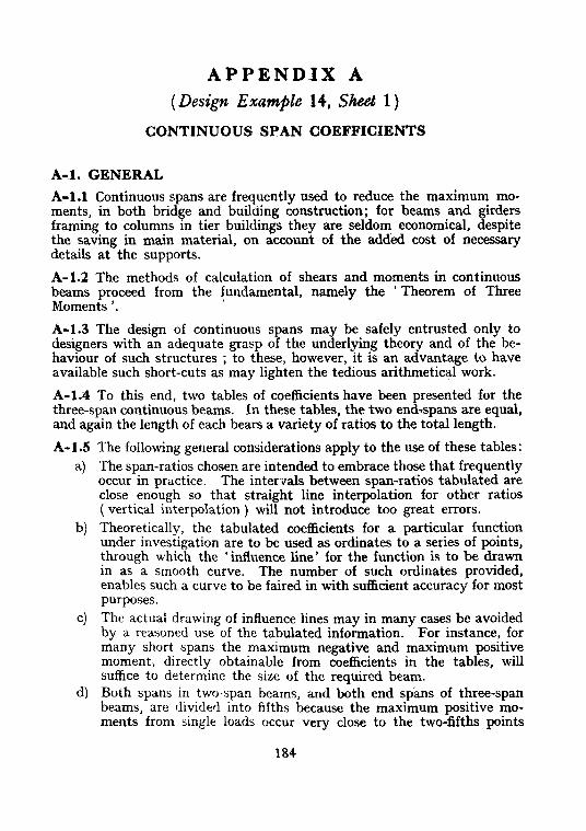
APPENDIX A (Design Example 14, Sheet 1)
CONTINUOUS SPAN COEFFICIENTS
A-ml. GENERAL
A-l.1 Continuous spans are frequently used to reduce the maximum mo- ments, in both bridge and building construction; for beams and girders framing to columns in tier buildings they are seldom economical, despite the saving in main material, on account of the added cost of necessary details at the supports.
A-1.2 The methods of calculation of shears and moments in continuous beams proceed from the fundamental, namely the ’ Theorem of Three Moments ‘.
A-l.3 The design of continuous spans may be safely entrusted only to designers with an adequate grasp ~of the underlying theory and of the be- haviour of such structures ; to these, however, it is an advantage to have available such short-cuts as may lighten the tedious arithmetical work.
A-1.4 To this end, two tables of coefficients have been presented for the three-span continuous beams. In these tables, the two end-spans are equal, and again the length of each bears a variety of ratios to the total length.
A-l.5 The following general considerations apply to the use of these tables:
a) The span-ratios chosen are intended to embrace those that frequently occur in practice. The intervals between span-ratios tabulated are close enough so that straight line interpolation for other ratios ( vertical interpolation ) will not introduce too great errors.
b) Theoretically, the tabulated coefficients for a particular function under investigation are to be used as ordinates to a series of points, through which the ‘influence line’ for the function is to be drawn in as a smooth curve. The number of such ordinates provided, enables such a curve to be faired in with sufficient accuracy for most purposes.
C) The actual drawing of influence lines may in many cases be avoided by a reasoned use of the tabulated information. For instance, for many short spans the maximum negative and maximum positive moment, djrectly obtainable from coefficients in the tables, will suffice to determine the size of the required beam.
d) Both spans in two-span beams, and both end spans of three-span beams, are divided into fifths because the maximum positive mo- ments from single loads occur very close to the two-fifths points
184

APPENDIX A
from the end supports. The central span of three-span beams is divided into fourths because this maximum occurs at mid-span.
e) The spacing of a specified group of concentrated loads is apt to be such that with one load placed at one of the fifth or quarter points tabulated, other loads fall between such points. Exact coefficients for such loads do not result from straight-line interpolation ( hori- zontal interpolation ) between the tabulated coefficients to right and to left, because the influence line between those points is a curve. Only in regions of sharp curvature, however, the error is important, and a mental correction to the straight-line interpolation, taking into account the direction of curvature of t?: influence line, is feasible.
f) All shear and moment coefficients have been expressed in terms of ‘ L ‘, the total length of .the two ( or three ) ‘spans. This is done in order that if, as is frequently the case, the total length is fixed and the intermediate span lengths are subject to the designer’s discretion, comparison of the various functions for various layouts may be made on a common and constant basis.
.A-2. THREE-SPAN TABLES
A-2.1 Table V gives the four reactions due to a unit load placedsuccessively at each of fifteen points. Since the end spans are equal, two of these re- actions are in reverse to the other two.
For moving groups of two or more loads, it will usually be desirable to plot the influence lines for all the shears and moments required in the design. The influence line ordinates for the maximum negative moment are tabulated (M,). Maximum positive moment will occur at an undeter- mined point, but this point will lie not far from the point where a single load produces maximum moment; the position of this point is tabulated [see + M(MAX)]. I n fl uence lines may be drawn, from the reaction tables, for this point and for other points close by, and these will envelop the influence line for absolute maximum positive moment in the ,span.
For longer spans, where changes of section will need to be made, the influence ordinates for moment (and sometimes for shear ) may be calculated (fromthe reaction tables) at each of the fifth points. From these the maximum moment at each fifth point may be found and plotted to scale, and a moment curve faired through the eleven points thus established. This will provide the information for a detailed design for bending stress.
A-2.2 Table VI has been given to simplify the calculation of the shears and moments usually required in the case of uniform load per lineal foot.
Load covering one end span (M,) produces positive moment through- out that span ( except quite close to the intermediate support ) and in the

lsl HANDBOOR FOR STRUCTURAL ENGINBRRS: STEEL BEAMS AND PLATE GIRDBRS
other end span to and including its intermediate support: and produces negative moment throughout the centre span ( except quite close to the far intermediate support ). Load covering the centre span ( M, ) produces positive moment throughout that span (except quite close to the inter- mediate supports) and produces negative moment throughout both end spans to and including the intermediate supports.
Therefore, load covering all *three spans (M,) does not produce the maximum moment at any point, but the coefficients as tabulated will often be required for the case of dead load.
For uniform live loading, the numerically greatest moment will occur at some points with one span, at some with two adjacent spans, and at some with two end spans, loaded. The coefficients for these moments are tabulated as Max M. Inspection will show what combinations of M,, M, and M, reversed, produce them. The same is true of Rev M, the greatest moment of opposite sign to Max M.
186


TABLE VP THRPE-SPAN SYMMETRICAL CONTINUOUS BEAMS ( Coefkients for Uniformly Distributed Loads )
( Clause ;\-2.2 j
Maximum shear (x WL ) is the maximum sheal on the indicated side of the support, due to uniform load of w per lin m in the most effective posi- tion for shear.
M, and M, ( XWL’) are the moments at the indicated points due to uniform load w covering respectively the left and the centre span. ( Jfoments from load covering the right hand span are the reverse from left to, right of MI .?nd are not ,tnbulated.)
M, = nmment at the indicated point due to load covering all spans; which 1s not a, conktlon fof maxlm~nl. Mu M = maximum pasihle moment of either sign at the indicated point, and IS due to umform load coveiing one,complete span or two
complete spans. The maximum possible positive momc~~t occurs close to, and IS negligibly greater than, that shown at Pomts 2 and 2’. Rev M = maximum moment of reverse sicn tp Mar M.
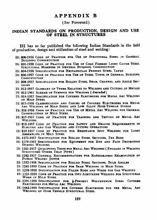
APPENDIX B
(See Foreword)
INDIAN STANDARDS ON PRODUCTION, DESIGN AND USE OF STEEL IN STRUCTURES
IS1 fias so far published the following Indian Standards in the field of production, design And utilization of steel and welding:
IS: 80+1956 CODE OF PRACTICE FOR USE OF STRUCTURAL STEEL IN GENERAL BUILDING CONSTRUCTION
IS: 801-1958 CODE OF PRACTICE FOR USE OF COLD FORMED LIGHT GAUGE STEEL STRUCTURAL MBMBERS IN GENERAL BUILDING CONSTRUCTION
IS: 804-1958 SPECIFICATION FOR RECTANGULAR PRESSED STEEL TANKS IS: 806-1957 CODE OF PRACTICE WR USE go STEEL TUBES. II GENERAL BUILDING
CONSTRUCTION IS: SOS-1957 SPECIFICATION FOR ROLLED STBBL BEAM, CHANNEL AND ANGLE SEC-
TIONS IS: 812-1957 GLOSSARY OF TERMS RELATING TO WELDING AND CUTTING OF METALS IS: 813-1961 SCHEME OF SYMROLS FOR WELDING ( Amcrdcd) IS: 814-1957 SPECIFICATION FOR COVERED ELECIRODES FOG METAL ARC WELDING
OF MILD STEEL IS: 815-1956 CLASSIFICATION AND CODING OF COVERED ELECTRODES FOR METAL
ARC WELDING .OF MILD STEEL AND LOW ALLOY HIGH-TENSILE STEELS IS: 816-1956 CODE OF PRACTICE FOR USE OF METAL ARC WELDING FOR GENERAL
CONSTRUCTION IN MILD STEEL IS: ~$;~~~~~CODE OF PRACTICE FOR TRAINING AND TESTING OF METAL ARC
IS: 818-1957 CODE 6~ PRACTICE lr~~ SAFETY AND HEALTH REQUIREMENTS IN ELECTRIC AND GAS WELDING AND CUTTING OPERATIONS
IS: 819-1957 CODE OF PRACTICE FOR RE~ISTAT?CE SPOT WELDING FOR LIGHT ASSEMBLIES IN MILD SIBEL
IS: 1173-1957 SPECIFICATION FOR ROLLED STEEL SECTIONS, TEE BARS IS: ~~~~-~~~~‘SPECIFICATION FOR EQUIPINSNT FOR EYE AND FACR PR~TBCTION
DURING WELDING IS: 1181-1957 QUALIFYING TESTS FOR ME,T~~: ARC WELDERS ( ENGAGED IN WgLDixiG
STRUCTURES STEER THAN APES ) IS: 1182-1957 GENERAL RJZCOMYBNDATIONS WR RADIOCRAPEIC EXAYINATI~N OF
FUSION WELDED JOINTS IS: 1252-1958 SPECIFICATION FOR ROLLED STEEL SECTIONS, BULB ANGLB~ IS: 1261-1959 CODE OF PRACTICE -FOP SEAM WELDING IN MILD STEEL IS: 1278-1958 SPECIFICATION FOR FILLER Robs AND WIRES FOR GAS WELDING IS: 1323-1959 CODE OF PRACTICE FOR OXY-ACETYLENE WELDING FOR STRUCTUIUL
WORK IN MILD STEEL IS: 1395-1959 SPECIFICATION FOR )-PEUCENT MOLYBDENUM STEEL COV~RZD
ELECTRODES FOR METAL ARC WELDING IS: 1442-1959 SPECIFICATION FOR COWERED ELECTRODES FOR THB METAL ARC
WELDING OF HIGH TEN&E STRUCTURAL STEEL
189

APPENDIX C ( See Foreword )
COMPOSITION OF STR’UCTURAL ENGINEERING SECTIONAL COMMITTEE, SMDC 7
The IS1 Structural Engineering Sectional .Committee, SMDC 7, which was responsible for processing t&is Handbook, consists of the following:
Chairman DIRECTOR STANDARDS ( CIVIL ) Railway Board ( Ministry of Railways )
Members SHRI P. BALAKRISHNAN Public Works Department, Madras
SHRI I). I. PAUL ( Allcvnnle )
SHRI B. N. BANNER.IEE Bridge & Roof Co. ( India) Ltd., Calcutta SHRI RAGHUDAS BAUL Public Works Department, Calcutta COL G. BENJAMIN Engineer-in-Chief’s Branch, Army Headquarters
SHRI R. S. MEHANURU ( ANwflczle ) SHRI J. 6. BODHE K. R. Irani & Co., Bombay SHRI D. S. DESAI institution of Engineers ( India ), Calcutta Mu. F. J. FONSECA Richardson & Cruddas Ltd., Bombay
MR. W. FERNANDES ( Alternaie ) JOINT DIRECTOR STPINDARDS Railway Board ( Ministry of Railways )
(B & S) DEPUTY DIRECTOR STAND-
ARDS ( B & S ) ( Altenzale ) SHRI S. C. KAPUR Central Public Works Department, New Delhi SHRI C. P. MALIK National Buildings Organization ( Ministry of
Works, Housing & Supply ) SHRI SHRI KRISHNA ( .4Zternate )
SHRI L. R. MARWADI Hindustan Construction Co. Ltd., Bombay SHRI P. S. MEHTA .New Standard Engineering Co. Ltd., Bombay SHRI B. N. MOZUMDAR Inspection Wing, Directorate General of Supplies &
Disposals ( Ministry of Works, Housing 8~ Supply ) SHRI P. L. DAS (A ltevnate ) SHRI Y. K. MURTHY Central Water & Power Commission ( Water Wing ),
New Delhi SWRI M. P. NACARSHETH Ministry of Transport & Communications ( Roads
Wing ) SHRI C. M. SHAHAN~ Braithwaite, Burn & Jessop Construction CO. Ltd.,
Calcutta SHRI SARUP SINGH Committee on Plan Project, Planning Commission,
SHk1 T. S. VEDAGIRI (.4&rnate ) New Delhi
SHRI D. S. THAKUR Bombay Municipal Corporation, Bombay SHRI A. R. VAINGANKAR (Alternate )
MA] R. P. E. VAZIFDAR Bombay Port Trust, Bombay SHRI V. VENVGOPALAN Central Water & Power Commission ( Power Wing ).
New Delhi SHRI S. S. MURTHY (Alternate )
DR. LAL C. VERMAN ( Ex-oficio ) SHRI B. S. K~IS’HNAMACHAR
Director, Indian Standards Institution Deputy Director ( S & M ), Indian Standards
( Alternate ) Institution Secretary
SHRI H. N. KRISHNAMURTHY Assistant Director ( S & M ), Indian Standards Institution
190