structural fuse concept for bridges - school of …bruneau/icc10acce bah… · ·...
TRANSCRIPT
International Conference in Commemoration of the 10th Anniversary of the 1999 Chi-Chi Earthquake, Taiwan September 17~21, 2009
Structural Fuse Concept for Bridges
Samer El-Bahey1 and Michel Bruneau2* 1 PhD Candidate, State University of New York at Buffalo (U.S.A.)
2 Professor, State University of New York at Buffalo (U.S.A.)
ABSTRACT
The concept of designing sacrificial elements to dissipate seismic energy while preserving the integrity of the structure’s other main components is known as the structural fuse concept. Few implementations of the structural fuse concept have been rigorous in emphasizing easy and complete replaceability of the sacrificial elements and absence of damage to the primary load-resisting structural system. Here, the concept is applied to an innovative multi-column accelerated bridge construction (ABC) pier concept. Different types of structural fuses are investigated to compare the effect of each on ABC bridge bents. A three span continuous bridge Prototype having two twin-column pier bents with fixed base spaced at 36m (120 ft) and 9m (30 ft ) tall, was designed according to the AASHTO LRFD bridge design specifications [1]. Its piers were designed using double composite rectangular columns using Bi-Steel panels and structural fuses. Two corresponding 1.5 scale models were developed and were tested at the Structural Engineering and Earthquake Simulation Laboratory (SEESL) at the University at Buffalo. The two specimens were designed for a maximum horizontal force of 400kips. Three quasi-static tests were performed. For the 1st specimen Steel Plate Shear Links (SPSLs) were installed between the columns as a series of structural fuses. Testing was performed up to a drift corresponding to the onset of column yielding to investigate the effectiveness of adding the fuses in dissipating the seismic energy, then testing continued till column failure. Then, the other specimen was installed and tested utilizing Buckling Restrained Braces (BRBs) as a series of structural fuses. The BRBs were then removed and bare frame cyclic test was performed until reaching failure of the columns.
Keywords: Structural Fuses, Cyclic tests, Seismic Analysis, Links, Buckling Restrained Braces
INTRODUCTION
Earthquakes can cause significant damage to bridge substructures which may cause collapse and loss of life.
The ability of a system to deform inelastically without significant loss of strength or stiffness can improve its seismic response avoiding catastrophic collapses. Providing reliable mechanisms for dissipation of the destructive earthquake energy is key for the safety of structures against intense earthquakes. The benefit of the inelastic deformation is that it can limit the forces in the members allowing reasonable design dimensions; also it provides hysteretic energy dissipation to the system. The concept of designing some sacrificial members dissipating the seismic energy while preserving the integrity of other main components is known as the structural fuse concept [2-5]. Here, a structural fuse concept is proposed in which structural steel elements are added to the bridge bent to increase its strength and stiffness, and also designed to sustain the seismic demand and dissipate all the seismic energy through hysteretic behavior of the fuses, while keeping the bridge piers elastic. Several types of structural fuses can be used and implemented in bridges; the focus in this paper will be on using two types of structural fuses.
* Corresponding author: Professor, Department of Civil, Structural and Environmental Engineering, University at Buffalo, Buffalo, NY 14260, [email protected]
International Conference in Commemoration of the 10th Anniversary of the 1999 Chi-Chi Earthquake, Taiwan September 17~21, 2009
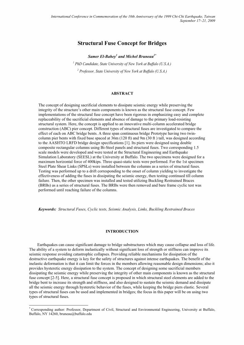
First, an innovative Steel Plate Shear Link (SPSL) is introduced, The proposed SPSL shown in figure 1
consists of a steel plate restrained from out of plane buckling using a concrete encasement and an unbonding material, the steel plate is designed to yield in shear reaching (0.6Fy) dissipating the seismic energy.
Figure 1: Proposed Link Sketch
Three Types of plastic mechanisms can develop in links regardless of the shape of the cross section. The
type of the plastic mechanism developed depends mainly on the link length in which links can be categorized into:
�� Flexural links (pure flexural yielding) developing full plastic moment hinges pM at the ends of the links and shear force less than the full plastic shear force pV and dissipating energy by flexural plastic rotation.
�� Shear links (pure shear yielding) developing full plastic shear force pV over the entire length of the link, with moments at the ends less that the plastic moment reduced to account for the presence of shear
rpM and dissipating energy by shear plastic distortion.
�� Intermediate links which are links yielding in both flexure and shear using the Von Mises yield criteria assuming that one yielding mode develops after the other mode strain hardens.
Various experimental studies has been done on links by previous researchers and it was found out that shear links exhibits the most stable and ductile cyclic behavior. Kasai and Popov [6] studied the behavior of shear links (short links) and concluded that the inelastic shear strains are fairly uniformly distributed over the entire length of the link which permits the development of large inelastic deformations without the presence of high local strains. It was found out that a well detailed link can sustain a plastic rotation of 0.1 radian without failure. Engelhardt and Popov [7] studied the behavior of flexural links (long links) and concluded that high bending strains at the ends develops to produce the inelastic deformation from which a flexural link was found to sustain a plastic rotation of 0.02 radian which is about 5 times less than a shear link. Berman and Bruneau [8-9] also studied the behavior or tubular links in eccentrically braced frames.
The ultimate failure mode for shear links is inelastic web shear buckling, delaying that failure mode was
also studied by [10] by adding vertical stiffeners, simple rules where developed to calculate the stiffeners spacing according to the maximum inelastic link rotation.
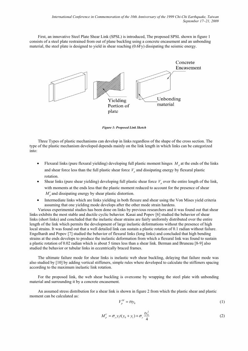
For the proposed link, the web shear buckling is overcome by wrapping the steel plate with unbonding
material and surrounding it by a concrete encasement. An assumed stress distribution for a shear link is shown in figure 2 from which the plastic shear and plastic
moment can be calculated as: 0
MpV ty�� (1)
20
1 0 1( )4
Vp y y
tyM y t y y� �� � � (2)
International Conference in Commemoration of the 10th Anniversary of the 1999 Chi-Chi Earthquake, Taiwan September 17~21, 2009
where MpV is the plastic shear force in presence of moment for section A-A, V
pM is the plastic moment in presence of shear force for section B-B, and y� is the yield stress of the plate.
The balanced length, *e , from which the transition of behavior occurs from flexural to shear can be calculated as:
* 0332 1 tan
2
ye
�
�� � �� �
(3)
while the balanced link angle, *� , can be calculated as:
2 * *0 02 2tan tan 0
3y ye e
� �� � � (4)
Figure 2: Assumed Stress Distribution in Mid and End plate
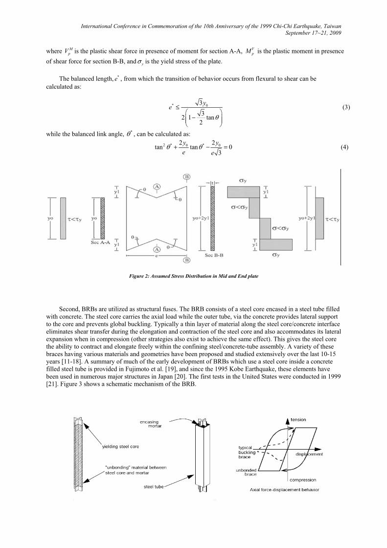
Second, BRBs are utilized as structural fuses. The BRB consists of a steel core encased in a steel tube filled with concrete. The steel core carries the axial load while the outer tube, via the concrete provides lateral support to the core and prevents global buckling. Typically a thin layer of material along the steel core/concrete interface eliminates shear transfer during the elongation and contraction of the steel core and also accommodates its lateral expansion when in compression (other strategies also exist to achieve the same effect). This gives the steel core the ability to contract and elongate freely within the confining steel/concrete-tube assembly. A variety of these braces having various materials and geometries have been proposed and studied extensively over the last 10-15 years [11-18]. A summary of much of the early development of BRBs which use a steel core inside a concrete filled steel tube is provided in Fujimoto et al. [19], and since the 1995 Kobe Earthquake, these elements have been used in numerous major structures in Japan [20]. The first tests in the United States were conducted in 1999 [21]. Figure 3 shows a schematic mechanism of the BRB.
International Conference in Commemoration of the 10th Anniversary of the 1999 Chi-Chi Earthquake, Taiwan September 17~21, 2009
Figure 3: Schematic Mechanism of the BRB (Clark et al. [22])
EXPERIMENTAL SETUP, INSTRUMENTATIONS AND LOADING PROTOCOL
A series of quasi-static cyclic tests has been performed using the recommended Applied Technology
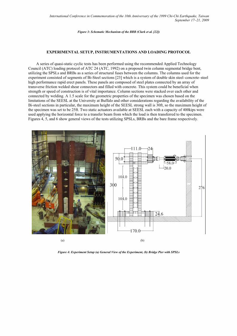
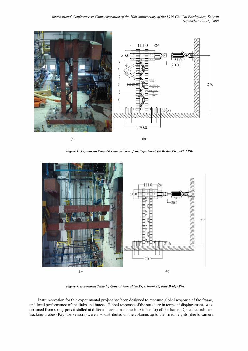
Council (ATC) loading protocol of ATC 24 (ATC, 1992) on a proposed twin column segmental bridge bent, utilizing the SPSLs and BRBs as a series of structural fuses between the columns. The columns used for the experiment consisted of segments of Bi-Steel sections [23] which is a system of double skin steel–concrete–steel high performance rapid erect panels. These panels are composed of steel plates connected by an array of transverse friction welded shear connectors and filled with concrete. This system could be beneficial when strength or speed of construction is of vital importance. Column sections were stacked over each other and connected by welding. A 1.5 scale for the geometric properties of the specimen was chosen based on the limitations of the SEESL at the University at Buffalo and other considerations regarding the availability of the Bi-steel sections in particular, the maximum height of the SEESL strong wall is 30ft, so the maximum height of the specimen was set to be 25ft. Two static actuators available at SEESL each with a capacity of 400kips were used applying the horizontal force to a transfer beam from which the load is then transferred to the specimen. Figures 4, 5, and 6 show general views of the tests utilizing SPSLs, BRBs and the bare frame respectively.
(a) (b)
Figure 4: Experiment Setup (a) General View of the Experiment, (b) Bridge Pier with SPSLs
International Conference in Commemoration of the 10th Anniversary of the 1999 Chi-Chi Earthquake, Taiwan September 17~21, 2009
(a) (b)
Figure 5: Experiment Setup (a) General View of the Experiment, (b) Bridge Pier with BRBs
(a) (b)
Figure 6: Experiment Setup (a) General View of the Experiment, (b) Bare Bridge Pier
Instrumentation for this experimental project has been designed to measure global response of the frame, and local performance of the links and braces. Global response of the structure in terms of displacements was obtained from string-pots installed at different levels from the base to the top of the frame. Optical coordinate tracking probes (Krypton sensors) were also distributed on the columns up to their mid heights (due to camera

International Conference in Commemoration of the 10th Anniversary of the 1999 Chi-Chi Earthquake, Taiwan September 17~21, 2009
range constrains) to measure displacement response at specific points. Seismic response of the columns was obtained from strain gages installed at critical points (top and bottom of each column), to determine whether these columns remain elastic during the test, recalling that one of the objectives of this experiment is to assess the effectiveness of the structural fuse concept to prevent damage in columns. Axial deformations of the BRBs were measured with String-Pots installed in parallel with the braces and connected to the gusset-plates. To measure strains in the SPSLs, 30-60 degree rosettes were installed at the midpoint of a few critical links. To ensure that no slippage or uplift occurs in the base, horizontal and vertical transducers were installed at its four corners.
EXPERIMENTAL RESULTS
For the first specimen with the SPSLs, loading was performed up to a drift level corresponding to the onset
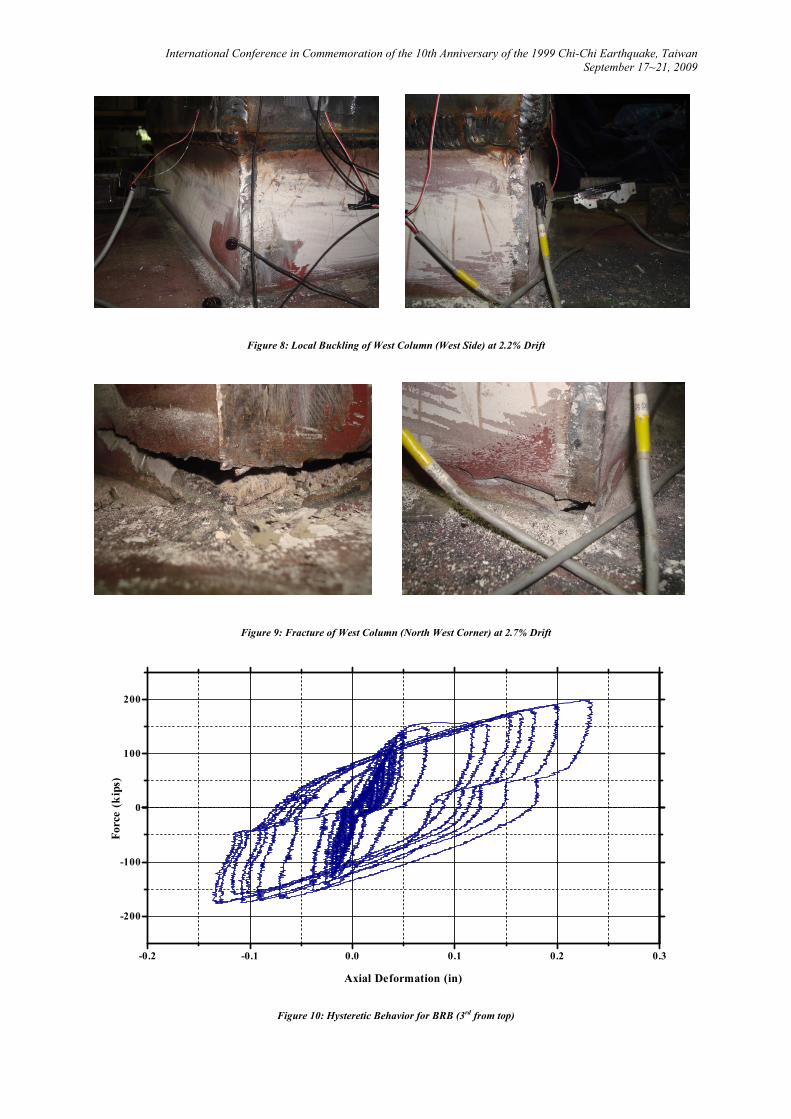
of column yielding to ensure that energy dissipation was through the SPSLs, then testing continued until fracture occurred at the base of both columns. This specimen reached a ductility ratio of 4 and drift of 1.5% without any sign of plastic deformation in the columns, figure 7 shows the hysteretic behavior at that level of drift. Signs of local buckling started to occur at the west column at a drift level of 2.2% as shown in figure 8, and the same column fractured at a drift level of 2.7% and the load dropped almost 33% as shown in figure 9.
For the second specimen with BRBs, loading was performed up to a drift level corresponding to the onset
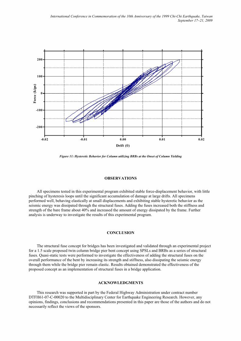
of column yielding (1.5%); also a ductility of 4 was reached, and no signs of plastic deformation were observed for both columns. The BRBs exhibited stable hysteretic behavior. Figure 10 shows the hysteretic behavior for one of the BRBs installed (3rd from top) plotted against the total system force. A small amount of slippage occurred due to the pin connection of the BRBs. Hysteretic behavior for the specimen with BRBs is shown in figure 11.
-0.04 -0.02 0.00 0.02 0.04
-200
-100
0
100
200
Drift (�)
Forc
e (k
ips)
Figure 7: Hysteretic Behavior for Column utilizing SPSLs at the Onset of Column Yielding
International Conference in Commemoration of the 10th Anniversary of the 1999 Chi-Chi Earthquake, Taiwan September 17~21, 2009
Figure 8: Local Buckling of West Column (West Side) at 2.2% Drift
Figure 9: Fracture of West Column (North West Corner) at 2.7% Drift
-0.2 -0.1 0.0 0.1 0.2 0.3
-200
-100
0
100
200
Axial Deformation (in)
Forc
e (k
ips)
Figure 10: Hysteretic Behavior for BRB (3rd from top)
International Conference in Commemoration of the 10th Anniversary of the 1999 Chi-Chi Earthquake, Taiwan September 17~21, 2009
-0.02 -0.01 0.00 0.01 0.02
-200
-100
0
100
200
Drift (�)
Forc
e (k
ips)
Figure 11: Hysteretic Behavior for Column utilizing BRBs at the Onset of Column Yielding
OBSERVATIONS
All specimens tested in this experimental program exhibited stable force-displacement behavior, with little
pinching of hysteresis loops until the significant accumulation of damage at large drifts. All specimens performed well, behaving elastically at small displacements and exhibiting stable hysteretic behavior as the seismic energy was dissipated through the structural fuses. Adding the fuses increased both the stiffness and strength of the bare frame about 40% and increased the amount of energy dissipated by the frame. Further analysis is underway to investigate the results of this experimental program.
CONCLUSION
The structural fuse concept for bridges has been investigated and validated through an experimental project
for a 1.5 scale proposed twin column bridge pier bent concept using SPSLs and BRBs as a series of structural fuses. Quasi-static tests were performed to investigate the effectiveness of adding the structural fuses on the overall performance of the bent by increasing its strength and stiffness, also dissipating the seismic energy through them while the bridge pier remain elastic. Results obtained demonstrated the effectiveness of the proposed concept as an implementation of structural fuses in a bridge application.
ACKNOWLEDGMENTS
This research was supported in part by the Federal Highway Administration under contract number DTFH61-07-C-00020 to the Multidisciplinary Center for Earthquake Engineering Research. However, any opinions, findings, conclusions and recommendations presented in this paper are those of the authors and do not necessarily reflect the views of the sponsors.
International Conference in Commemoration of the 10th Anniversary of the 1999 Chi-Chi Earthquake, Taiwan September 17~21, 2009
REFERENCES
[1] L. AASHTO, "Bridge Design Specifications, Customary US Units, with 2008 Interim Revisions," American
Association of State Highway and Transportation Officials, Washington, DC, 2008.
[2] Y. Huang, et al., "Damage tolerant structures with hysteretic dampers," Journal of Structural Engineering, vol. 40, pp. 221-234, 1994.
[3] J. Fellow, et al., "Damage-controlled structures. I: Preliminary design methodology for seismically active regions," Journal of Structural Engineering, vol. 123, p. 423, 1997.
[4] R. Vargas and M. Bruneau, "Analytical Investigation of the Structural Fuse Concept," Report No. MCEER-06, vol. 4, 2006.
[5] R. Vargas and M. Bruneau, "Experimental Investigation of the Structural Fuse Concept," Report No. MCEER-06, vol. 5, 2006.
[6] K. Kasai and E. Popov, "General behavior of WF steel shear link beams," Journal of Structural Engineering, vol. 112, pp. 362-382, 1986.
[7] M. Engelhardt and E. Popov, "Behavior of long links in eccentrically braced frames," Report No. UCB/EERC-89, vol. 1, 1989.
[8] J. Berman and M. Bruneau, "Experimental and analytical investigation of tubular links for eccentrically braced frames," Engineering Structures, vol. 29, pp. 1929-1938, 2007.
[9] J. Berman and M. Bruneau, "Further Developments of Tubular Eccentrically Braced Frame Links for the Seismic Retrofit of Braced Steel Truss Bridge Piers," 2007.
[10] K. Kasai and E. Popov, "Cyclic web buckling control for shear link beams," Journal of Structural Engineering, vol. 112, pp. 505-523, 1986.
[11] E. Saeki, et al., "Experimental study on practical-scale unbonded braces," Journal of Structural and Constructional Engineering, Architectural Institute of Japan, vol. 476, pp. 149-158, 1995.
[12] H. HASEGAWA, et al., "Experimental study on dynamic behavior of unbonded-braces," Journal of Architecture, vol. 114, pp. 103-106, 1999.
[13] M. Iwata, et al., "Buckling-restrained braces as hysteretic dampers," 2000, p. 33.
[14] C. Black, et al., Component testing, stability analysis and characterization of buckling-restrained unbonded braces: Pacific Earthquake Engineering Research Center, 2002.
[15] W. Lopez, et al., "Lessons learned from large-scale tests of unbonded braced frame subassemblage," 2002, pp. 171-183.
[16] R. Sabelli, et al., "Seismic demands on steel braced frame buildings with buckling-restrained braces," Engineering Structures, vol. 25, pp. 655-666, 2003.
[17] W. López and R. Sabelli, "Seismic design of buckling-restrained braced frames," Steel Tips, Structural Steel Education Council (www. steeltips. org), 2004.
[18] M. M. Mamoru Iwata, "Buckling-restrained brace using steel mortar planks; performance evaluation as a hysteretic damper," vol. 35, ed, 2006, pp. 1807-1826.
[19] M. Fujimoto, et al., "A study on the unbonded brace encased in buckling-restraining concrete and steel tube," Journal of Structural and Construction Engineering, AIJ, vol. 34, pp. 249-258, 1988.
[20] P. Reina and D. Normile, "Fully braced for seismic survival," Engineering News-Record, pp. 34–36, 1997.
[21] I. Aiken, et al., "Large-Scale Testing of Buckling Restrained Braced Frames," 2002, pp. 35-44.
[22] P. Clark, et al., "Large-scale testing of steel unbonded braces for energy dissipation," 2000.
[23] H. Bowerman, et al., "Bi-Steel design and construction guide," British Steel Ltd, Scunthorpe (London), 1999.