structural fire design methods for reinforced concrete … · the comprehensive analysis of...
TRANSCRIPT
* PhD. Eng. Krzysztof Chudyba, PhD. Eng. Szymon Seręga, Institute for Building Material and Struc-tures, Faculty of Civil Engineering, Cracow University of Technology.
KRZYSZTOF CHUDYBA, SZYMON SERĘGA*
STRUCTURAL FIRE DESIGN METHODS FOR REINFORCED CONCRETE MEMBERS
METODY PROJEKTOWANIA ELEMENTÓW ŻELBETOWYCH Z UWAGI NA WARUNKI POŻAROWE
A b s t r a c t
The paper presents methods for determining fire resistance of reinforced concrete members according to Eurocode 2-1-2 (simplified methods based on the effective cross-section and incremental-iterative approach) [3]. Results of conducted calculations are compared with fire test results taken from the literature. The main parameters considered in the conducted analysis are: concrete class, values of normal force eccentricity and cross-section shape. General conclusions are formulated as to the accuracy of simplified methods and practical limitations of their application within the analysed scope of variable material and geometrical parameters.
Keywords: concrete structures, fire resistance, simplified methods
S t r e s z c z e n i e
W artykule przedstawiono metody określania odporności ogniowej elementów żelbetowych według normy EN 1992-1-2 [3] (metody uproszczone bazujące na przekroju zredukowanym oraz podejście przyrostowo-iteracyjne). Rezultaty obliczeń porównano z wynikami badań ogniowych dostępnych w literaturze. W analizie obliczeniowej rozważono następujące para-metry: klasę betonu, mimośród siły podłużnej, kształt przekroju. Sformułowano wnioski odno-śnie dokładności metod uproszczonych i praktycznych ograniczeń ich stosowania w zakresie analizowanych zmiennych materiałowych i geometrycznych.
Słowa kluczowe: konstrukcje betonowe, odporność ogniowa, metody uproszczone
TECHNICAL TRANSACTIONSCIVIL ENGINEERING
1-B/2013
CZASOPISMO TECHNICZNEBUDOWNICTWO
16
1. Introduction
In general, reinforced concrete structural members exhibit good performance under fire conditions. This is due to the fact that thermal conductivity of concrete is relatively low at room temperature and decreases with increasing temperature. As long as concrete is not damaged as a result of excessive cracking or spalling, it constitutes effective protection for reinforcing steel against high temperature occurring during fire.
The comprehensive analysis of reinforced concrete structures under the specified fire scenario includes thermal analysis (determination of temperature distribution within each point of structural elements) and mechanical analysis (evaluation of structural response to determined temperature fields). In order to carry out these analyses, it is necessary to possess detailed information as to numerous material properties (physical, thermal, mechanical – both for structural concrete and for reinforcing steel) which are the functions of temperature, for example basing on [1], as well as to operate with appropriate computational tools for coping with advanced thermo-hydro-mechanical material models for the structure.
A properly designed reinforced concrete structure is characterized in normal design conditions by a certain reserve in bearing capacity:
. ( 0)d d fiR E E t≥ > = (1)
where: R – the load bearing capacity, Ed – a design value of an effect of actions according to [2], Ed.fi(t = 0) – a design effect of actions in fire situations at the beginning of a fire.
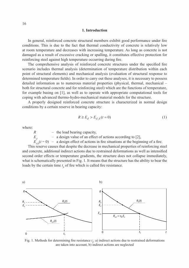
This reserve causes that despite the decrease in mechanical properties of reinforcing steel and concrete, additional indirect actions due to restrained deformations as well as intensified second order effects or temperature gradients, the structure does not collapse immediately, what is schematically presented in Fig. 1. It means that the structure has the ability to bear the loads by the certain time tfi of fire which is called fire resistance.
a) b)
Fig. 1. Methods for determining fire resistance tfi: a) indirect actions due to restrained deformations are taken into account, b) indirect actions are neglected
17
Usually, the indirect actions should be considered in the analysis of fire resistance tfi of concrete structures. However, when high accuracy is not required or if an isolated structural member is analysed, these actions can be neglected and internal forces may be estimated from the following equation [3]:
.1.
1 2 .1 .1
k fi kd fi fi d fi
G k Q k
G QE E
G Q+ψ
= η η =δ γ + δ γ
(2)
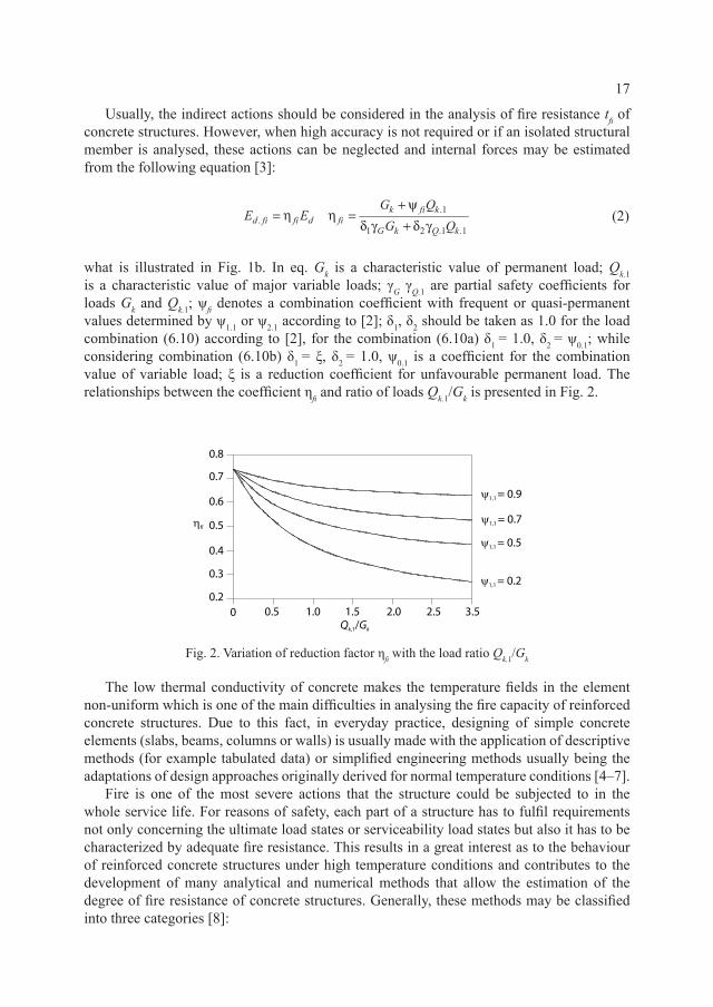
what is illustrated in Fig. 1b. In eq. Gk is a characteristic value of permanent load; Qk.1 is a characteristic value of major variable loads; γG γQ.1 are partial safety coefficients for loads Gk and Qk.1; ψfi denotes a combination coefficient with frequent or quasi-permanent values determined by ψ1.1 or ψ2.1 according to [2]; δ1, δ2 should be taken as 1.0 for the load combination (6.10) according to [2], for the combination (6.10a) δ1 = 1.0, δ2 = ψ0.1; while considering combination (6.10b) δ1 = ξ, δ2 = 1.0, ψ0.1 is a coefficient for the combination value of variable load; ξ is a reduction coefficient for unfavourable permanent load. The relationships between the coefficient ηfi and ratio of loads Qk.1/Gk is presented in Fig. 2.
Fig. 2. Variation of reduction factor ηfi with the load ratio Qk,1/Gk
The low thermal conductivity of concrete makes the temperature fields in the element non-uniform which is one of the main difficulties in analysing the fire capacity of reinforced concrete structures. Due to this fact, in everyday practice, designing of simple concrete elements (slabs, beams, columns or walls) is usually made with the application of descriptive methods (for example tabulated data) or simplified engineering methods usually being the adaptations of design approaches originally derived for normal temperature conditions [4–7].
Fire is one of the most severe actions that the structure could be subjected to in the whole service life. For reasons of safety, each part of a structure has to fulfil requirements not only concerning the ultimate load states or serviceability load states but also it has to be characterized by adequate fire resistance. This results in a great interest as to the behaviour of reinforced concrete structures under high temperature conditions and contributes to the development of many analytical and numerical methods that allow the estimation of the degree of fire resistance of concrete structures. Generally, these methods may be classified into three categories [8]:
18
– tabulated data for well-recognized design solutions, – simplified engineering methods (e.g. 500°C isotherm method or zone method) for
specified types of structural elements, – advanced thermo-mechanical or thermo-hydro-mechanical material models of steel and
concrete for numerical modelling of parts of structures or for the whole structure.The first category usually consists of sets of tables, where minimum distances from the
centre of steel bars to the heated edge of cross-section and minimum section’s dimensions for required fire resistance are provided. Estimating the fire resistance on the basis of the tabulated data is straightforward but also has significant limitations. Tabular data cover a relatively limited range of design cases – for example, tables in [3, 9] can be applied only for the ISO 834 standard fire time-temperature curve or similar and for normal strength concrete. Moreover, this type of method does not allow the determination of the actual fire load bearing capacity Rfi(t) for specified time t or fire resistance tfi for specified Ed.fi.
Simplified engineering methods, i.e. the 500°C isotherm method and the zone method, will be described in detail and discussed further in the paper within the light of their accuracy and validity for determining the fire resistance for compressed reinforced concrete elements and cross-sections.
For advanced calculation methods, many physical models taking into account temperature, moisture and mechanical fields both for concrete and steel have been worked out. Generally, thermal analysis should be carried out with taking into account principles of heat and moisture flow with temperature dependent physical material characteristics. For mechanical analysis of material response for loads – both mechanical and thermal – there should be taken into account total strains including the following components: free thermal strain, immediate mechanical strain, basic (isothermal) creep strain and creep strain in transient conditions.
Advanced thermo-mechanical or thermo-hydro-mechanical models are valuable tools for better understanding of different phenomena occurring in concrete structures in fire and constitute important supplements for experimental research. However, in the case of everyday designing practices which are limited to standard structural solutions, the advanced methods are too complex to apply. Thus there is a strong need for developing simplified methods for determining Rfi(t) function which do not have the disadvantages of the tabular methods. In addition, simplified design methods for typical reinforced concrete elements under accidental fire conditions provide an engineer with a certain level of insight and control over conducted calculation procedures and may also constitute an initial design stage for complex non-typical structures.
2. Simplified methods for determining fire load capacity of RC sections according to Eurocode 2-1-2
Simplified methods may be applied mainly for determining the load bearing capacity of a cross-section in a fire situation for elements where the plane cross-sections hypothesis remains valid. Additionally, the following assumptions are presumed: – deformations due to fire actions do not influence the thermal field, – free thermal strains are omitted in the analysis, – there are omitted or taken into account indirectly transient creep strains in thermal
conditions. Additional strains may be considered in stress-strain relationships of concrete
19
assumed for analysis, determined from experiments in transient thermal conditions (for example physical relationships given in [3]),
– stresses acting in a perpendicular direction to the elements axis resulted from temperature gradients are omitted, assuming the same material mechanical characteristics as for an uniaxial state of stress,
– explosive spalling of concrete is not taken into account, – concrete tensile strength is omitted, – there is assumed the full bound between reinforcing steel and surrounding concrete during
the whole process of heating of an element.The simplified methods included in Eurocode 2-1-2 [3] are supplemented with assumptions concerning both the manner of reducing the material strengths during high temperature action and the reduction of dimensions of a cross-section.
In [3] there are proposed three simplified methods for determining fire resistance of concrete elements such as beams or columns. The first two are based on the so-called “effective section”: the 500°C isotherm method and zone method. The third method is the incremental-iterative procedure where for any axial force Nu (Nu ≤ Nu0, Nu0 – the load bearing capacity of axially loaded element) the ultimate bending moment Mu is determined on the basis of bending moment – curvature diagram. The main disadvantage of the latter is the fact that for every value Nu the bending moment – curvature diagram has to be constructed, which is more time consuming and laborious in comparison with the aforementioned methods.
Despite the methods included in Eurocode 2-1-2 [3], there are many simplified procedures for determining fire resistance developed especially for columns. In order to estimate fire load capacity of isolated concrete columns, the simple Rankine formula is employed [10–11] or researchers extend the procedures of their national codes for structures design at room temperature for the cases of fire actions [4–7].
2.1. Method of 500°C isotherm
The method of 500°C isotherm was developed in the 70-ties of the last century by Swedish researchers [12] and was introduced into Eurocode 2-1-2 [3] and the CEB-FIP Bulletin [9].
The basis of this method constitutes an observation that the reduction in compressive strength of concrete is not significant within the temperature range from 20°C to 500°C. After exceeding the temperature level of 500°C, compressive strength of concrete radically decreases, reaching at temperature 700°C the value of only about 30% of initial strength. Hence, it was assumed that the thickness az by which the cross-sectional dimensions are to be reduced due to fire effects, should be determined by the location of 500°C isotherm. As a result, a new shape of cross-section of the element is created within the 500°C isotherm being the restricting line (Fig. 3). Concrete properties within the new cross-section are the same as for normal temperature. Reduction of yielding stress of reinforcing steel is conducted as the function of temperature level at the centre of each bar despite their location with regard to the 500°C isotherm.
Having determined the reduced cross-section dimensions and the reduced level of yielding stress for steel, the load bearing capacity in fire situation for element Rfi at time t is calculated on the basis of the commonly accepted methods for reinforced concrete elements analysis in normal temperature conditions.

20
Fig. 3. Reduced cross-section of reinfroced concrete beam or column in 500°C isotherm method
The method of 500°C isotherm is relatively simple and may be applied for all cross-section shapes and different heating scenarios (fire from both sides of load-bearing walls, fire from all four sides for columns, etc.) but it also has some limitations. It was worked out and experimentally verified for elements made of normal strength concrete (NSC) that were subjected to failure due to exceeding the capacity of tensile reinforcement and usually not heated from the compressive side (beams, slabs heated from the bottom side). For compressed elements, especially when an eccentricity of a normal force is small, and for elements made of high strength concrete (HSC) 500°C isotherm method may overestimate the load bearing capacity in a fire situation that was earlier indicated in [13–15].
2.2. Zone method
The zone method, that constitutes an alternative to the 500°C isotherm method, was worked out in the eighties of the last century by K. Hertz [16]. Eurocode 2-1-2 [3] recommends its application for elements subjected to a bending moment and a compressive normal force.
In Fig. 4 there are presented assumptions and basic notations for which the effective cross-section dimensions are to be determined. Considering the section of wall heated from both sides, it is possible to evaluate the temperature distribution by solving transient but one-dimensional heat flow problems. Having temperature distribution θ(x), one may determine maximum stress that may be carried by each of the concrete fibres fc(θ(x)). It is assumed that the compressive strength of concrete for the middle part of the cross-section bfi = 2w – 2az has a constant value equal to fc(θM), where θM denotes the temperature in the coldest concrete fibre. For the analysed case, it is the fibre located in the middle of the wall. The thickness of the layer az is determined from the equality of the area below the graph of fc(θ(x)) and the area of a rectangle with a width of bfi and a height equal to fc(θM):
( )
( )
( )
( )1
( )
12
w n
c c iw i
z fc fcc M c M
f x dx ka w
w f n k− =
θ θ = − δ δ = ≅ ⋅ θ ⋅ θ
∫ ∑ (3)
21
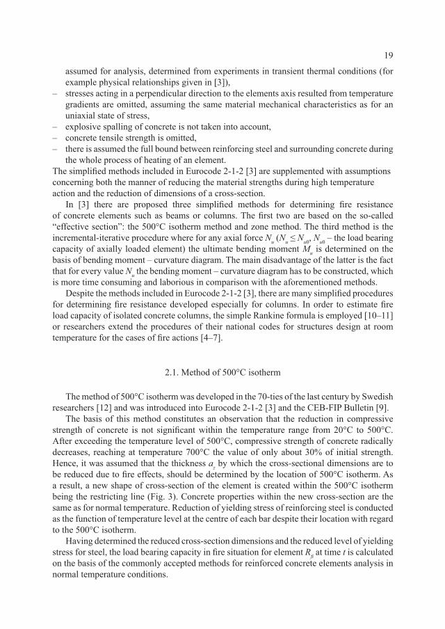
In equation (3), kc(θ) is the ratio of concrete compressive strength at temperature θ to the value at normal temperature. By dividing the width w into n equal parts (n ≥ 3) and by calculating the temperature in the middle of each layer θi, the integral in the equation for δfc may be approximately substituted by the sum.
Fig. 4. Assumptions and notations for zone method
In Appendix B for Eurocode 2-1-2 [3], the equation for δfc is given in the transformed version. For thin divisions n, the modified form of equation (4) takes into account significant variation in temperature within the zone of each division:
( )
( )1
1151
n
c ii
z fc fcc M
kna w
n k=
θ− = − δ δ = θ
∑ (4)
Detailed information as to the reduction of cross-sectional dimensions by a value az for different shapes is included in Appendix B of Eurocode 2-1-2 [3].
The fire resistance Rfi(t) for zone method is determined – similarly to the 500°C isotherm method – using classical methods of concrete structures theory. Calculations are being carried out for the reduced geometry of cross-sections, reduced yielding stress for steel fy.red = ks(θs)fy(20°C) (θs – temperature of reinforcing steel) and for reduced concrete compressive strength evaluated from the relationship fc.red = kc(θM)fc(20°C).
2.3. Incremental-iterative method
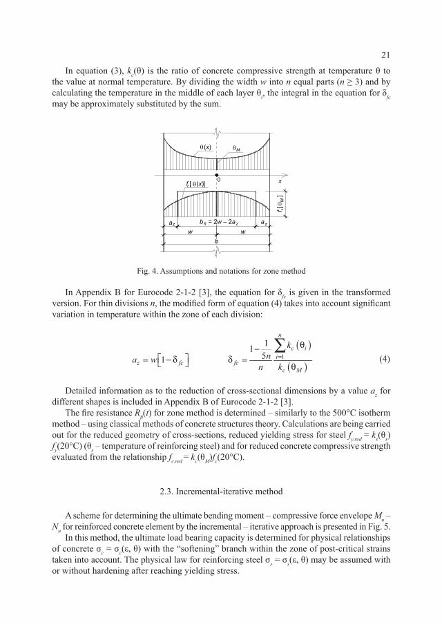
A scheme for determining the ultimate bending moment – compressive force envelope Mu – Nu for reinforced concrete element by the incremental – iterative approach is presented in Fig. 5.
In this method, the ultimate load bearing capacity is determined for physical relationships of concrete σc = σc(ε, θ) with the “softening” branch within the zone of post-critical strains taken into account. The physical law for reinforcing steel σs = σs(ε, θ) may be assumed with or without hardening after reaching yielding stress.
22
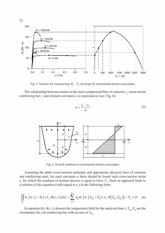
Fig. 5. Scheme for constructing Mu – Nu envelope by incremental-iterative procedure
The relationship between strains in the most compressed fibre of concrete εc, most tensile reinforcing bar εs and element curvature κ is expressed as (see: Fig. 6):
c s
dε − ε
κ = (5)
Fig. 6. Overall notations in incremental-iterative procedure
Assuming the plain cross-sections principle and appropriate physical laws of concrete and reinforcing steel, for each curvature κ there should be found such cross-section strain εc for which the resultant of normal stresses is equal to force Nu. Such an approach leads to a solution of the equation (with regard to εc) in the following form:
( )( ) ( ) ( )( )1 11
; ( , ) ; , 0S
c
N
c c c Sj s Sj c Sj Sj ujA
z h y z dA A Z h Y Z N=
σ κ ⋅ − + ε θ + σ κ ⋅ − + ε θ − =∑∫∫ (6)
In equation (6). θ(y, z) denotes the temperature field for the analyzed time t, YSj, ZSj are the coordinates for j-th reinforcing bar with an area of ASj.

23
The ultimate value of bending moment Mu that corresponds to normal force Nu is the maximum value for the function M = M(κ):
( )( ) ( ) ( )( )1 11
max ; ( , ) ; ,S
c
N
u c c c Sj Sj s Sj c Sj SjjA
M z h y z zdA A Z Z h Y Z=
= σ κ ⋅ − + ε θ + σ κ ⋅ − + ε θ
∑∫∫
(7)
which is illustrated in Fig. 5.It is worth mentioning that constructing Mu – Nu envelopes by the incremental-iterative
procedure is a time-consuming process, requiring calculations based on solving ni × nj equations (ni denotes the number of levels of normal force Nu and nj – number of considered curvatures) to determine the relationship M = M(κ) and find maximum values Mu. Hence, this approach is used mainly in theoretical analyses, usually as a reference method with which results obtained from other methods are compared.
3. Parametric study
In order to compare the results provided by the above described methods for determining fire load capacity, the parametric study for a few of the most commonly used in everyday design practice cross-sections of reinforced concrete elements was carried out. Two shapes of the cross-sections were analysed: square – with the dimensions of 30 cm × 30 cm and 40 cm × 40 cm and circular – with the diameters of 30 cm, 50 cm and 70 cm. The reinforcement of the square cross-sections consists of 8ø20 bars (reinforcement ratio ρs = 2.8%) and 8 ø25 bars (ρs = 2.5%) respectively for the 30 cm × 30 cm and the 40 cm × 40 cm elements. For the circular cross-sections, the reinforcement consists of 8ø16 (ρs = 2.3%), 8ø25 (ρs = 2.0%), 10ø32 (ρs = 2.1%), for diameters of 30 cm, 50 cm, 70 cm, respectively. The calculations were performed for normal strength concrete (NSC) fc = 30 MPa and high strength concrete (HSC) fc = 90 MPa for the elements with square cross-sections. In the case of the members with circular cross-sections, the compressive strength of 55MPa was taken into account. The yield strength of steel was the same for all considered cross-sections and equal to 420 MPa.
3.1. Thermal analysis
Each element was heated uniformly along the perimeter according to the ISO834 time-temperature fire scenario. The heat transfer between the fire environment and a structural element is held by convection (Newton’s Law) and thermal radiation (Stephan-Boltzman’s Law). The physical parameters describing convective and thermal radiation heat fluxes at the element surface were taken to analysis according to Eurocode 1-1-2 [17]: the coefficient of heat transfer by convection αk = 25 W/(m2K); emissivity of the heat source (fire) εf = 1.0;

24
surface emissivity of a structural member εf = 0.8; surface configuration factor equal to 1.0; Stephan-Boltzman constant σS-B = 5.67 · 10-8 W/(m2K4).
Thermal profiles were obtained by solving the classical Fourier-Kirchhoff equation:
ddt
cpθρ θ θ λ θ θ( ) ( ) ( )= ∇ ∇( ) (8)
where:ρ – density of concrete, cp – specific heat and λ denotes thermal conductivity.
Numerical computations were carried out using the finite element code ANSYS [18] for the following thermal properties of concrete: – for NSC, the thermal properties according to [3] were applied as for siliceous aggregate
concrete with moisture content equal to 3% and the upper limit of thermal conductivity, – for HSC, the thermal properties were taken according to [19] as for siliceous aggregate
concrete.The circular cross-sections were modelled in axisymmetry (temperature fields are only
the function of radius), whereas for the square cross-sections, the two-dimensional analysis was conducted. For the sake of simplicity, the influence of steel on the thermal fields was neglected. The temperature of steel bars were taken equal the temperature of concrete at a centroid of the steel bar. The examples of calculated thermal fields are presented in Fig. 7 and 8 for circular and square cross-sections, respectively.
Fig. 7. Temperature profiles for circular cross-sections

25
Fig. 8. Temperature profiles for square cross-sections
3.2. Mechanical analysis
The mechanical calculations were performed according to the assumptions listed in paragraph 2. For the 500°C isotherm method, the classical stress-strain relationships for concrete in the form of “Madrid parabola” [20] were used. The same σc – εc curves were applied to the zone method, although the compressive strength of concrete was reduced to kc(θM)·fc. The elastic ideal plastic physical relationships for steel with reduced yield strength to ks(θs)·fy were taken into account, both for the 500°C isotherm method and the zone method. Interaction envelopes Mu – Nu for the reduced dimensions of the analysed cross-sections were constructed according to the classical limit strain analysis for reinforced concrete sections at normal temperature [20].
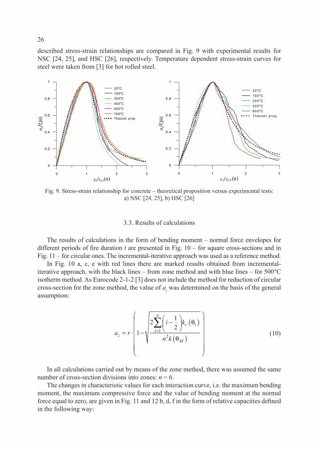
The stress-strain relationships of concrete with the full softening branch were used for the reference method – incremental – iterative procedure. The pre-peak behaviour of NSC is described by the equations given in Eurocode 2-1-2 [3]. Since the Eurocode 2-1-2 [3] does not provide the formula for descending branch of σc – εc relationships, the following equation is proposed [21]:
( )2
1( )1
1, ( ) 10 ( )c
cp
c c c c cf ε θ
− − ε σ ε θ = θ ⋅ ε > ε θ (9)
where εc1(θ) is the strain at the peak in the σc – εc diagram and p = 3.0. The pre-peak behaviour of σc – εc curves of HSC were taken from [22], however, the
values of fc(θ)/fc(20°C) and εc1(θ) were assumed according to experimental results given in [23]. The post-peak behaviour of HSC was described by equation (9) with p = 2.5. The above
26
described stress-strain relationships are compared in Fig. 9 with experimental results for NSC [24, 25], and HSC [26], respectively. Temperature dependent stress-strain curves for steel were taken from [3] for hot rolled steel.
Fig. 9. Stress-strain relationship for concrete – theoretical proposition versus experimental tests: a) NSC [24, 25], b) HSC [26]
3.3. Results of calculations
The results of calculations in the form of bending moment – normal force envelopes for different periods of fire duration t are presented in Fig. 10 – for square cross-sections and in Fig. 11 – for circular ones. The incremental-iterative approach was used as a reference method.
In Fig. 10 a, c, e with red lines there are marked results obtained from incremental-iterative approach, with the black lines – from zone method and with blue lines – for 500°C isotherm method. As Eurocode 2-1-2 [3] does not include the method for reduction of circular cross-section for the zone method, the value of az was determined on the basis of the general assumption:
( )
( )1
2
122
1
n
c ii
zM
i ka r
n k=
− θ = ⋅ −
θ
∑ (10)
In all calculations carried out by means of the zone method, there was assumed the same number of cross-section divisions into zones: n = 6.
The changes in characteristic values for each interaction curve, i.e. the maximum bending moment, the maximum compressive force and the value of bending moment at the normal force equal to zero, are given in Fig. 11 and 12 b, d, f in the form of relative capacities defined in the following way:

27
max max 01 2 30 0 0
max max 0, ,
t t tN
t t tN
N M MN M M
== = =
=
α = α = α = (11)
where:
max ,tN max ,tM 0
tNM =
– maximum compressive force, maximum bending moment and maximum bending moment for normal force equals zero carried out at the moment t of heating, respectively,
0max ,tN = 0
max ,tM = 00
tNM == – as above, but calculated for the beginning of the heating
process of the element.
Fig. 10. Mu – Nu interaction envelopes for the incremental-iterative procedure (red line), the zone method (black line), and the 500°C isotherm method (blue line) – square cross-section
The resulting interaction curves are similar for all analysed types of cross-section. With the increase of heating duration, ultimate curves Mu – Nu are subjected to “shrinking” and deformation of shape.
All presented methods lead to similar results for cross-section subjected to a bending moment – see: Fig. 11 e, f and 12 f. This observation converges well with earlier results that were published in the literature [13–14]. Bent cross-sections with ratio of reinforcement of about 1% exhibit the tensile failure mode. The exertion levels of compressive zone of cross-section, plays a less significant role here despite the fact that it is also subjected to fire effects.
a) b)
c) d)

28
Fig. 11. Relative capacities for NSC members – a), c), e); HSC members – b), d), f)
a) b)
c) d)
e) f)
29
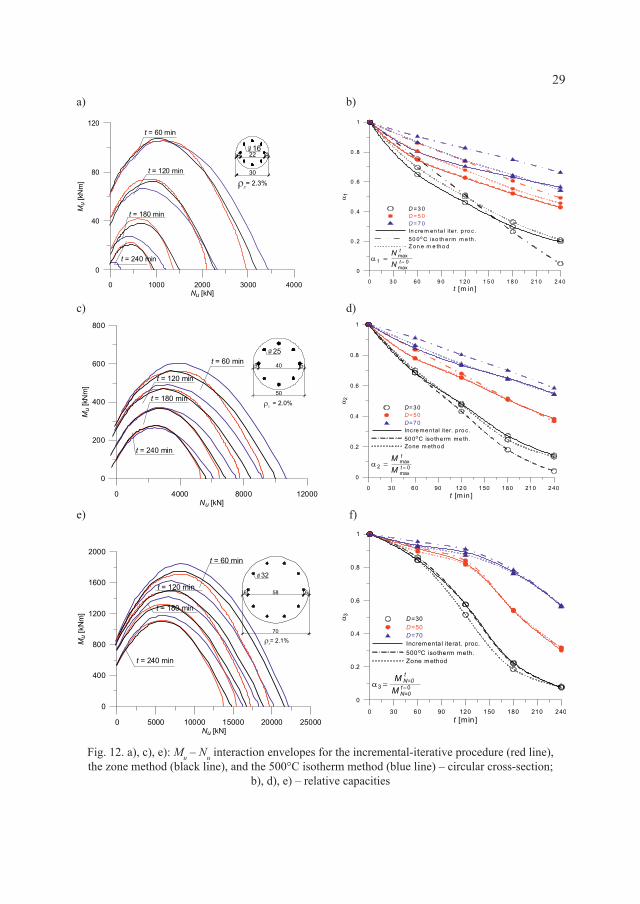
Fig. 12. a), c), e): Mu – Nu interaction envelopes for the incremental-iterative procedure (red line), the zone method (black line), and the 500°C isotherm method (blue line) – circular cross-section;
b), d), e) – relative capacities
a) b)
c) d)
e) f)
30
The differences in results between the incremental-iterative approach and the effective cross-section methods are observed for the cases where normal force is of great significance – see: Fig. 11 a–d and 12 b, d. It is especially important for elements made of HSC, where differences between incremental – iterative and 500°C isotherm methods are up to 40% for the unfavourable side of structural safety. For the zone method, differences are less important and do not exceed 15%, but they are also on the unsafe side.
4. Comparison of calculations with results of experiments
The analysis of the results for fire resistance for reinforced concrete cross-sections obtained from different considered methods (500°C isotherm method, zone method and incremental-iterative approach) is supplemented by the comparison of calculated values and by results from experiments carried out on elements subjected to a normal force usually acting on an accidental eccentricity.
Fire tests provide information of vital importance as to the real behaviour of reinforced concrete structural elements during the action of high temperature. Results from tests may be directly used for determining or checking the necessary standard fire resistance for elements. But most of all, they are useful as the reference value for determining the accuracy and validity range for calculation methods for structural elements under fire conditions.
For the estimation of accuracy of the results from the analytical methods with experiments, there were selected tests presented in [27–31]. Some results were excluded from the comparative analysis as during the tests there were observed the phenomenon of explosive spalling of concrete that led to a premature failure of these elements in the conducted experiments. The total number of test results selected for the comparison was equal to 56, from which 27 elements were made of high strength concrete and 29 – from normal strength concrete.
For each of 56 considered columns, calculations of temperature distribution were carried out whilst taking into account the aggregate type used for the concrete mix and the appropriate value of compressive concrete strength. Thermal conductivity and specific heat for normal strength concrete on silicate aggregate were assumed in compliance with [3] as for concrete with humidity equal to 3%. For normal strength concrete on calcareous aggregate, the thermal conductivity was also taken based on [3], but specific heat was assumed according to [19]. Thermal properties for high strength concrete were taken from [19]. There was assumed the same fire scenario according to ISO834 standard fire time – temperature curve for all 56 elements. Thermal analyses did not take into account the influence of reinforcing steel and stirrups onto the resulting temperature fields. For elements made of normal strength concrete, calculations were conducted twice – with accounting for the upper and the lower limits of thermal conductivity. The temperature distribution that provided results closest to those obtained from experiments was chosen for further analysis.
The first series of tests used for the comparative study was carried out in the laboratories at the University of Ghent and University of Liège. Four types of cross-sections were investigated in the experiments: 20 cm × 20 cm, 20 cm × 30 cm, 30 cm × 30 cm, 40 cm × 40 cm and two different heights of columns 2.1 m and 3.9 m. All columns were made of normal strength concrete with gravel aggregate. The heating process was realized according to the
31
ISO 834 standard fire curve. A detailed description of the tests can be found in [27]. Due to severe spalling, the premature failure was observed in some columns. Those elements were excluded from the theoretical analysis. In the present study, only nine columns with square cross-section of 30x30cm and 40 × 40 cm are analysed.
The second set of tests was done in National Research Council in Canada [28–31]. The effects of a load level, end conditions (pinned or fixed), section sizes and shapes (square, rectangular, circular), reinforcing steel ratio (1.7–4.38%), concrete strength (28–127 MPa), concrete admixtures (steel or polypropylene fibres) and kinds of coarse aggregate (siliceous, calcareous) on fire resistance of columns were investigated. All columns had the same height of 3.81 m and were subjected to the ASTM 119 fire curve which is very similar to the standard fire time – temperature curve according to ISO 834. Only these columns with a square cross-section and dimension of 30.5 cm × 30.5 cm, 40.6 cm × 40.6 cm were used in the comparative study.
Columns constitute structural elements for which second order effects play an important role. In the literature, there are only a few reports on the simplified methods of taking into account second order effects in calculating fire resistance of compressed reinforced concrete elements. Appropriate proposals consist in application of classical Rankine – Merchant formula [10, 11] used for steel elements or in modification of national recommendations for calculating the columns in normal temperature conditions [4–7].
Due to the lack of methods for taking into account the second order effects, there was proposed the approach based on recommendation of Eurocode 2-1-1 [20] with determination of a buckling force on the basis of ACI 318-99 [32] and with modification being analogous to that presented in [6, 7]. The first order moment is multiplied by the factor:
2
11
o
B
u
cNN
π
η = +−
(12)
where:NB – Euler buckling force, Nu – an applied load, co – a constant dependent on the first order moment distribution.
The Euler buckling force is calculated from the following equation:
( )( ) ( )2
2
0.2 , ,c
c cm s s iiA
Bo
I E y z t dA I E
Nl
π ⋅ θ + ⋅ θ =
∑∫∫ (13)
In eq. (13) Ic, Is are moments of inertia for concrete and steel sections, respectively, Ecm(θ) is the temperature dependent concrete elasticity modulus, Es(θ) is the steel elasticity modulus, θ(y, z, t) is the temperature field, θi is the temperature of i-th bar, lo is an effective length of column.

32
The load bearing capacity is strongly dependent on an accidental eccentricity eimp. For the present computations, eimp = 0.005 m was used for all analysed elements.
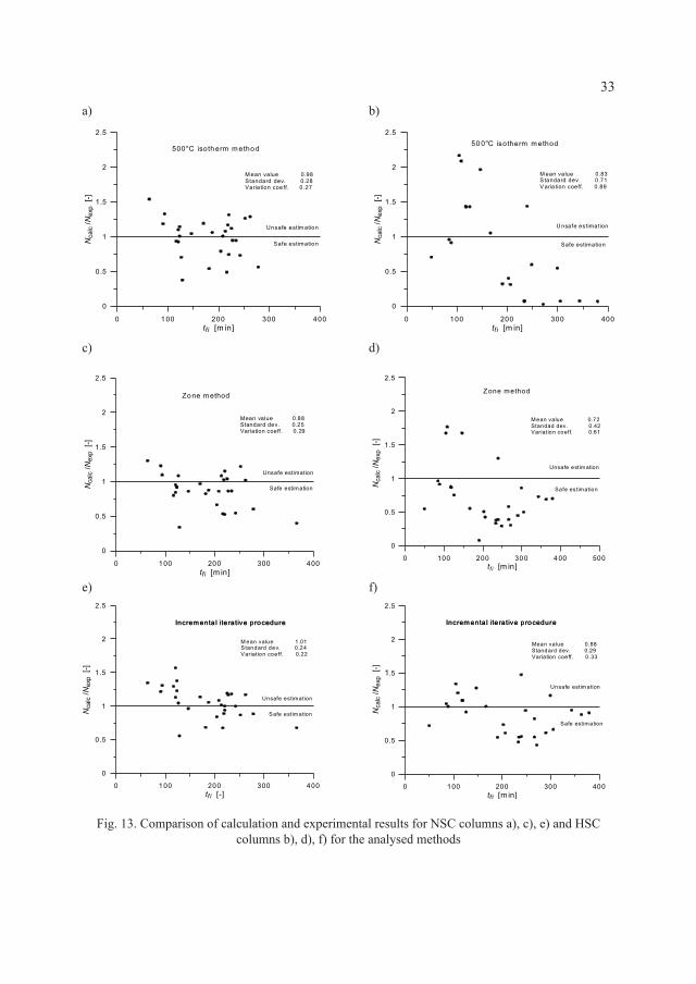
The comparison of the experimental results and calculated (theoretical) values obtained by the discussed methods for the considered set of cases is presented in Fig. 13. The calculated values of fire resistances Ncalc in most of the analysed examples differ from the test results Nexp. One of the reasons of this fact is that there is a lack of experimental data for physical properties of concrete used for experiments. The assumed thermal properties were taken from the literature which results in differences between the measured and calculated temperature distributions in the cross-sections. Moreover, during the initial phase of heating, there was observed (especially for HSC elements) local and surface thermal spalling. This effect, which results in faster heating of reinforcing steel bars and increased penetration of the heat within the cross-section, was not considered in the calculations.
The results obtained from the incremental-iterative approach, are the closest to the experimental ones, both for NSC and for HSC – Fig. 13 e, f. The mean value of the Ncalc/Nexp distribution for this method is the closest to 1.0 with the lowest variation coefficient obtained. The methods of the effective cross-section – the 500°C isotherm method and the zone method – lead to the reliable results only for elements made of NSC (Fig. 13 a, c).
The analysis of Ncalc/Nexp distributions for HSC elements – Fig. 13 b, d – indicates that the methods of the effective cross-section provide an unreliable estimation of fire load capacity. This is particularly true for the 500°C isotherm method which in most cases leads to meaningful under-estimation or over-estimation of fire resistance.
5. Summary and conclusions
The analysis of reinforced concrete members subjected to a fire action may be performed by many methods with different levels of complexity and accuracy. On the simplest practical level, descriptive methods in the form of tabulated data may be applied, but only within the ranges specified by appropriate codes. On the other hand, in recent years there has been observed significant progress in working out more and more sophisticated methods for the fire design of reinforced concrete members, taking advantage of modern computational tools and advanced material modelling.
In the paper, the emphasis was placed onto simplified methods for determining fire load capacity of reinforced concrete sections subjected to bending moment and normal force (also called engineering methods), which can be located between the two aforementioned extreme approaches. Despite advanced thermal and mechanical models for reinforced concrete elements (or the whole structures), there is still a strong need for developing and improving simplified design methods for everyday practices that are usually limited to more typical engineering solutions. Such methods should allow an engineer to exert control over calculation procedures carried out for fire design situations and may also constitute initial designs for complex, non-typical structures.
33
Fig. 13. Comparison of calculation and experimental results for NSC columns a), c), e) and HSC columns b), d), f) for the analysed methods
a) b)
c) d)
e) f)

34
The simplified methods that were presented, discussed and compared in the paper include those given in Eurocode 2-1-2 – two methods based on the effective cross-section (500oC isotherm method and zone method) and incremental-iterative approach. The basic aim of the conducted analysis was to compare results obtained by those different methods (treating the incremental-iterative approach as the reference method) as well as to compare calculated values of fire resistance with the experimental results for reinforced concrete columns taken from the literature, which would make it possible to evaluate the accuracy and possible safe range of the application of considered methods. Major variables in the parametric study were: concrete class (NSC, HSC), values of normal force eccentricity, cross-section shape and reinforcement ratio. The following general conclusions can be drawn from the conducted analysis:
The discussed methods provide similar results in the form of Mu – Nu envelopes for all analysed cross-section shapes and concrete classes but only for load cases close to pure bending. When normal force accompanies the bending moment, there are observed significant differences in results, especially for HSC members. Taking the incremental-iterative approach as a reference method, the difference may reach 40% for the isotherm method and 15% for the zone method – in both cases for unfavourable side of structure safety. This observation converges quite well with the findings of other researchers [13–14]. The differences in results obtained from the 500°C method for HSC members may to some extent be reduced by assuming a lower than 500°C level of limit temperature (as high strength concretes are characterized with faster reduction in compressive strength with increasing temperature in comparison with normal strength concrete) [14]. – In comparison with experimental results, the incremental-iterative approach indicates
relatively constant levels of accuracy within the whole analysed range of concrete class expressed by similar values of Ncalc/Nexp distribution parameters. For the methods of the effective cross-section, the differences between calculated and experimental results are more pronounced with significant dispersion of Ncalc/Nexp values, especially for HSC columns.
– The methods of the effective cross-section are to be considered as reliable only for elements made of NSC and generally subjected to bending. For normal force that accompany bending moments and for HSC members, they may significantly over or under-estimate fire resistance (in particular – the 500°C isotherm method).
– Incremental-iterative procedures applied for determining Mu – Nu interaction curves provide results closest to experimental ones within the whole analysed range of variables (concrete class, amount of reinforcement, duration of fire action, cross-section shape). Although this constitutes a more time-consuming process than designs based on effective cross-section methods, in general, it may operate with different real stress-strain relationships for materials (structural concrete and reinforcing steel) thus giving a possibility to account for variation in basic parameters for the whole set of materials used.
35
References
[1] Fire Design of Concrete Structures – materials, structures and modelling. fib bulletin 38, Lausanne, Switzerland, April 2007.
[2] EN 1990:2004 Eurocode. Basis of Structural Design, European Committee For Standardization, Brussels 2002
[3] EN 1992-1-2:2004. Eurocode 2: Design of concrete structures – Part 1.2: General rules – Structural fire design, European Committee For Standardization, Brussels 2004.
[4] Dotreppe J.-C., Fransen J.M., Vanderzeypen Y., Calculation method for design of reinforced concrete columns under fire conditions, ACI Structural Journal, 96 (1), January-February 1999.
[5] Franssen J.-M., Dotreppe J.-C., Fire tests and calculation methods for circular concrete columns, Fire Technology, 39 (1), January 2003.
[6] Tan K.H., Yao Y., Fire resistance of four-face heated reinforced concrete columns. Journal of Structural Engineering, 129 (9), September 2003.
[7] Tan K.H., Yao Y., Fire resistance of reinforced concrete columns subjected to 1-, 2-, and 3-face heating, Journal of Structural Engineering, 130 (11), November 2003.
[8] Fire Design of Concrete Structures – structural behaviour and assessment. fib bulletin No. 46, Lausanne, Switzerland, April 2008.
[9] Fire Design of Concrete Structures in Accordance with CEB/FIP Model Code 90. CEB Bulletin D’Information No. 208, Lausanne, Switzerland, July 1991.
[10] Tan K.H., Tang C.Y., Interaction formula for reinforced concrete columns in fire conditions, ACI Structural Journal, 101 (1), January-February 2004.
[11] Tan K.H., Yao Y., Rankine method for reinforced concrete columns under fire conditions, In Proceedings of the 18th Australian Conference on the Mechanics of Structures and Materials, Developments in Mechanics of Structures and Materials, vol. 1, Perth, Australia, December 2004.
[12] Andenberg Y., Analytical fire design of reinforced concrete structures based on real fire characteristics, In FIB Eight Congress Proceedings, Part 1, London 1978.
[13] Bamonte P., Meda A., Towards a simplified approach for the sectional analysis of R/C members in fire, In Proceedings of the 2nd International Congress Keep Concrete Attractive, Naples, Italy, June 5–8 2005.
[14] Meda A., Gambarova P.G., Bonomi M., High-performance concrete in fire-exposed reinforced concrete sections, ACI Structural Journal, 99 (3), May-June 2002.
[15] Seręga S., A new simplified method for determining fire resistance of reinforced concrete sections, In Proceedings of 6th International Conference Analytical Models and New Concepts in Concrete and Masonry Structures, 2008.
[16] Hertz K.D. Design of fire exposed concrete structures, Technical Report no. 160, CIB W15/81/20(DK), Technical University of Denmark, Lyngby 1981.
[17] 1991-1-2:2004 Eurocode 1: General Actions – Actions on structures exposed to fire. European Committee For Standardization, Brussels 2002.
[18] Kohnke P., editor, ANSYS, Inc. Theory Manual Twelfth Edition, 1994.[19] Kodur V.K.R., Sultan M.A., Effect of temperature on thermal properties of high-
strength concrete, Journal of Materials in Civil Engineering, 15 (2), April 2003.[20] EN 1992-1-1: Eurocode2: Design of concrete structures – Part 1: General rules and
recommendations for buildings. European Committee for Standardization, Brussels, 2004.
36
[21] Seręga S., Behaviour of high performance concrete columns at fire temperatures, PhD thesis, Cracow University of Technology, 2009, in Polish.
[22] Kodur V.K.R., Wang T.C., Cheng F.P., Predicting the fire resistance behaviour of high strength concrete columns, Cement & Concrete Composites, 26 (2), February 2004.
[23] Cheng F.P., Kodur V.K.R., Wang T.C.W., Stress-strain curves for high strength concrete at elevated temperatures, Journal of Materials in Civil Engineering, 16 (1), January-February 2004.
[24] Schneider U., Behaviour of concrete at high temperatures, Deutscher Ausschuss fur Stahlbeton, 337, 1982.
[25] Schneider U., Modelling of concrete behaviour at high temperatures, [w:] R.D. Anchor, H.L. Malhotra, J.A. Purkiss, editors, Design of structures against fire, 1986.
[26] Fu Y.F., Wong Y.L., Poon C.S., Tang C.A., Stress-strain behaviour of high-strength concrete at elevated temperatures, Magazine of Concrete Research, 57 (9), November 2005.
[27] Dotreppe J.-C., Franssen J.M., Braus R., Vandevelde P., Minne R., Van Nieuwenburg D., Lambotte H., Experimental research on the determination of the main parameters affecting the behaviour of reinforced concrete columns under fire conditions, Magazine of Concrete Research, 49(179), June 1996.
[28] Kodur V.K.R., Cheng F.P., Wang T.C., Latour J.C., Leroux P., Fire resistance of high-performance concrete columns, Technical Report No. 834, National Research Council, Institute for Research in Construction, Ottawa, December 2001.
[29] Kodur V.K.R., McGrath R., Latour J.C., MaClaurin J., Experimental studies on the fire endurance of high-strength concrete columns, Technical Report No. 919, National Research Council, Institute for Research in Construction, Ottawa, October 2000.
[30] Kodur V.K.R., McGrath R., Leroux P., Latour J.C., Experimental studies for evaluating the fire endurance of high-strength concrete columns, Technical Report No. 197, National Research Council, Institute for Research in Construction, Ottawa, May 2005.
[31] Lie T.T. Wooleton J.L., Fire resistance of reinforced concrete columns – test results, Technical Report No. 596, National Research Council, Institute for Research in Construction, Ottawa 1988.
[32] Building code requirements for structural concrete (ACI 318-99) and commentary (ACI 318R-99), American Concrete Institute, 1999.