structural engineers association of arizona –51 … convention/2017...1 structural engineers...
TRANSCRIPT
1
Structural Engineers Association of Arizona
– 51st Annual Conference
Micropile Design and Construction with Case Studies
By: Thomas A. Printz, P.E.
Vice President of Engineering
Williams Form Engineering Corp.
Topics of Discussion
• 1) Micropile Types
• 2) Micropile Design
• 3) Micropile Construction
• 4) Case Studies- Wyoming State Capitol Building, Cheyenne, WY
- Thomas Jefferson High School, San Antonio, TX
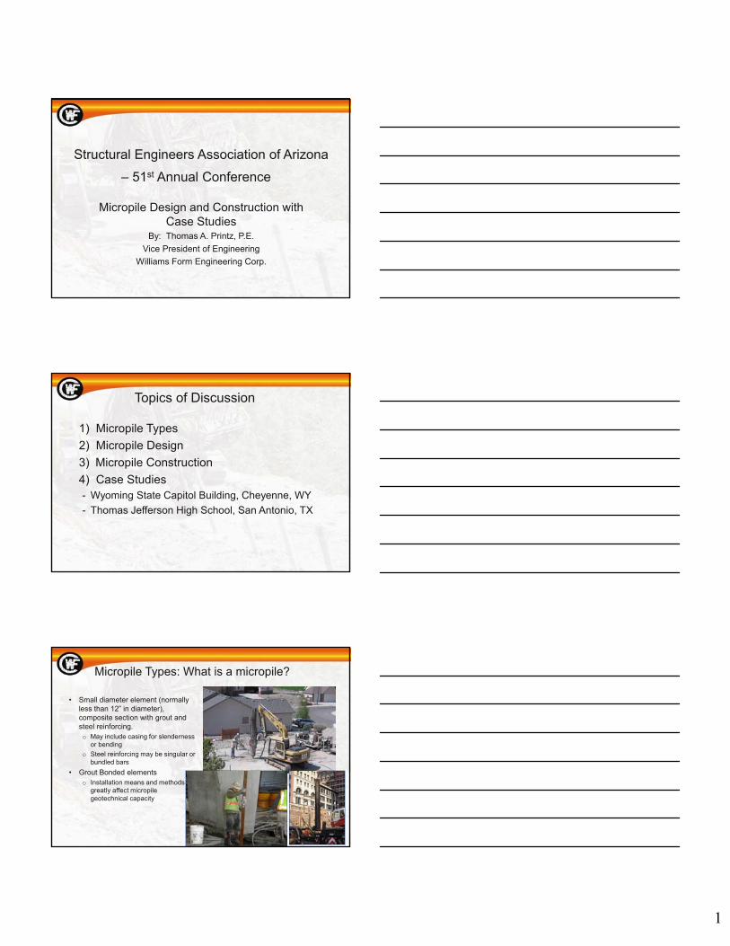
Micropile Types: What is a micropile?
• Small diameter element (normally less than 12” in diameter), composite section with grout and steel reinforcing.o May include casing for slenderness
or bending
o Steel reinforcing may be singular or bundled bars
• Grout Bonded elementso Installation means and methods
greatly affect micropile geotechnical capacity
2
Micropile Types: Case 1 Micropiles
• Directly Loaded Element
• Axial or Lateral Loading
• Structural resistance provided by steel reinforcement and/or casing
• Geotechnical resistance provided by grout to ground adhesion
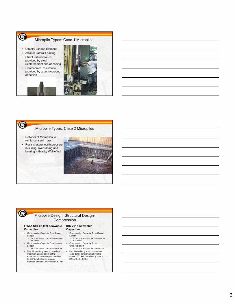
Micropile Types: Case 2 Micropiles
• Network of Micropiles to reinforce a soil mass
• Resists lateral earth pressure in sliding, overturning and bearing – Gravity Wall effect
Micropile Design: Structural Design-Compression
FHWA NHI-05-039 Allowable Capacities• Compression Capacity, P.c – Cased
Length– P.c = 0.40*A.grout*f’c + 0.47*fy.steel*(A.bar
+ A.casing)
• Compression Capacity, P.c - Uncased Length
– P.c = 0.40*A.grout*f’c + 0.47*fy.steel*A.bar
• Max Allowable fy.steel is based on maximum usable strain at the extreme concrete compression fiber (0.003”) multiplied by Young’s modulus of steel (29,000 ksi) = 87 ksi
IBC 2015 Allowable Capacities• Compression Capacity, P.c – Cased
Length– P.c = 0.33*A.grout*f’c + 0.40*fy.steel*(A.bar
+ A.casing)
• Compression Capacity, P.c –Uncased length
– P.c = 0.33*A.grout*f’c + 0.40*fy.steel*A.bar
• Max Allowable fy.steel is based on code defined maximum allowable stress of 32 ksi; therefore, fy.steel = 32 ksi/0.40 = 80 ksi

3
Micropile Design: Structural Design - Tension
• Composite Element – Tension– Reinforcing and Grout
Allowable Tension Load:Pt_allow = 0.55*fy_steel x A_bar (FHWA)Pt_allow = 0.60*fy_steel x A_bar (IBC)
Micropile Design: Structural Design -Tension/Compression
• Micropile Plunge Length
– A Portion of the micropile design load is transferred to the surrounding ground by the cased portion of the pile, reducing the load that must be supported by the uncased portion of the pile.
Ptransfer_allow = (bond/F.S.) x PI x d x (Plunge Length)
Or
Plunge Length = (Ptransfer_allow * F.S.)/(bond*PI*d)
Micropile Design: Structural Design - Lateral Load and Eccentricity
• Section properties are analyzed using Ensoft’s L-Pile software
– Inputs include structural element (pipe section, etc.)
– Soil layer properties
• Soil acts as a spring to provide lateral resistance
– Pile head loading condition
– Installation angle and pile head distance above ground
• ***Program provides deflection, maximum stress, maximum moment and degree of rotation of the pile head – Allowable Bending stress = 0.60*fy.steel***

4
Micropile Design: Structural Design - Connection Design
Consists of Micropile Element connection to the structure and is defined by:- American Concrete Institute (ACI 318-11 Appendix D)- American Institute of Steel Construction (AISC)- NHI-05-039 Micropile Design and Construction Manual (FHWA)
Micropile Design: Structural Design – Reinforcing Selection
• 75 KSI (Yield) 100 KSI (Ultimate)
• ASTM A615
Micropile Structural Design: Hollow bar reinforcing selection
• Simultaneous “Drill and Grout” operation!!!
• Perfect selection in collapsing ground conditions
• Grout maintains open drill hole and flushes debris

5
Micropile Geotechnical Design: Bond Length
• Lb = P/(π*d*tw)
– P = service load (lbs)
– d = drill hole diameter (in)
– tw = working bond stress (psi) = tu/2
– Lb = bond length (in)
Micropile Geotechnical Design: Micropile Groups
• Micropile Spacing– 30 inches or 3 micropile diameters (whichever is greater)
• Efficiency Factors for Micropile Groups• Evaluation of Micropile Group Uplift Capacity• Estimate Micropile Group Settlement
– Due to consolidation of soil layers below the micropile group– Include Elastic Displacement of Steel Material = PL/AE
• P = Design Load (lbs), L = Length (in), A = Steel Section Area (in^2),E = Young’s Modulus of Elasticity
Micropile Construction: Drilling Equipment
Rotary Percussion Cased hole drill
6
Micropile Construction: Drilling Methods
• Installation Methods – Simultaneous Drilling and Grouting with Hollow Bar System (unique installation
type)• Grout is the flushing mechanism• Effective hole diameters can increase tremendously depending on the permeability of
the soil• Drilling slurry is thickened to 0.4 to 0.45 w/c ratio after pile reaches depth
– Open Hole Drilling (Type A, C and D)• Air or water is used as the flushing mechanism• Gravity tremie grout• Post-Grouting
– Cased Hole Drilling (Type A, B, C and D)• Air is used as the flushing mechanism• Micropile element is installed through the casing• Casing is removed as the pile is tremie grouted, either gravity or pressure• Can be pressure tremie grout• Can be post-grouted
Micropile Construction: Grouting Techniques
• Type A Micropile - Gravity grouted micropile element– Micropile reinforcing is inserted down either an open or cased hole with a grout tube
attached and grout is tremied at low pressures from the bottom of the hole up. If the hole is cased, the casing is withdrawn during grouting operatons.
• Type B Micropile - Pressure grouted micropile element– Additional grout is injected under pressure after primary grout has be tremied and the
temporary casing is withdrawn.
• Type C Micropile – Post grouted micropile element– Grout is gravity tremied similar to Type A piles. 15-25 minutes later and before hardening of
the primary grout, similar grout is placed through a secondary post-grout tube at a minimum of 145 psi.
• Type D Micropile – Post Grouted micropile element– Grout is gravity tremied similar to Type A piles. After primary grout has hardened, similar
grout is placed through a secondary post-grout tube at pressures of 290-1,160 psi. The post-grout tube can be flushed after use and the post grouting process repeated several times, producing grout volumes as much as 250% of primary volumes.
Case Study 1: Wyoming State Capitol Building, Cheyenne, WY
• Owner: State of Wyoming
• Architect: HDR
• Structural Engineer: Silman
• Geotechnical Engineer: Terracon
• General Contractor: JE Dunn
• Micropile Design Build Contractor: Straight Line Construction

7
Case Study 1: Capitol building facts
• Built in 3 phases
– 1st phase started 1886 and was completed in 1888
– 2nd phase was completed in 1890
– 3rd phase was completed in 1917
• One of 20 State Capitols designated as a National Historic Landmark
• Wyoming saved for over 14 years to fund the renovation
• $110 million for the Capitol Building alone
• Restoration to include restoring original ceiling heights, upgrade to mechanical, electrical and plumbing as direct bury utilities and upgrade the exterior facade
• Capitol building settled during construction
• Interior excavation for new utilities cause zone of influence conflicts with existing rubble footings
• Utility crossings impacted existing footings
• Underpinning was required to accommodate crossings and zone of influence conflicts
Case Study 1: Underpinning Design Challenges
• Allowable ½” of additional settlement allowed, but only ¼” differential
• Masonry structure allowable deflection = L/600
• The building settled during construction, so under a layer of highly consolidated material, there was inadequate bearing strata
• Limited access drilling
• Very high wall loads, DL+LL up to 22 kips/ft
• Specifications allow only 4’ of open excavation under existing foundation at a time and sequencing keeps excavation trenches a minimum of 16’ from each other.
• Support of excavation required in underpinning pits
• Excavated material was deemed unsuitable for bearing material
• Various design methodologies were incorporated due to unknowns and conflicts with additions or upgrades over the years
– Micropile and needle beam underpinning
– Micropile and side load bracket underpinning
– Reticulated micropile earth retention and underpinning
Case Study 1: Building Overview
8
Case Study 1: Typical Underpinning Plan
Case Study 1: Typical Underpinning Plan with Utilities
Case Study 1: Micropile and Needle Beam Underpinning – Micropile Verification Test
• Preproduction Verification Test– Loaded to 200% of
design load
– Held for a minimum of 10 minutes at 130% of design load (creep test)
– If movement after constant load in 10 minutes is less 0.040”, test is complete
– If movement exceeds 0.040” in 10 minutes, creep test is extended another 50 minutes in which creep cannot exceed 0.080”
9
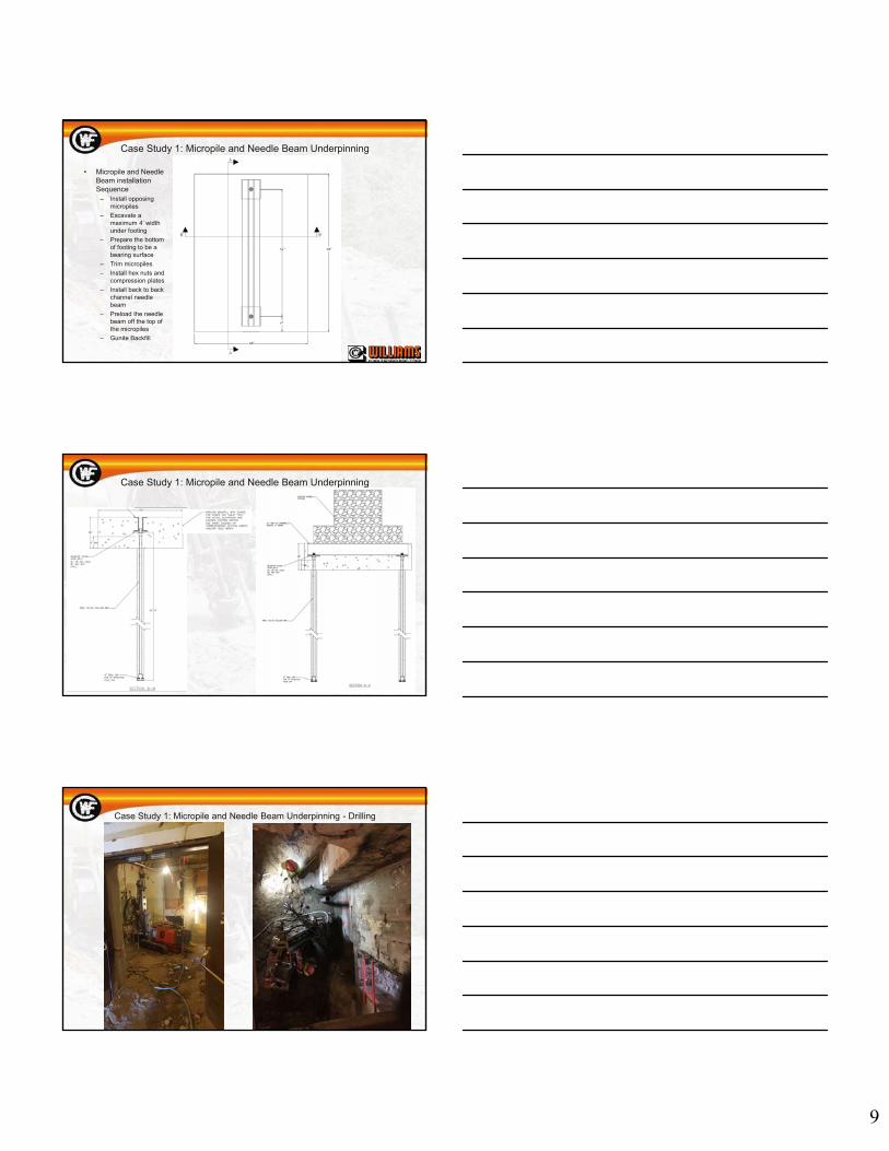
Case Study 1: Micropile and Needle Beam Underpinning
• Micropile and Needle Beam installation Sequence
– Install opposing micropiles
– Excavate a maximum 4’ width under footing
– Prepare the bottom of footing to be a bearing surface
– Trim micropiles
– Install hex nuts and compression plates
– Install back to back channel needle beam
– Preload the needle beam off the top of the micropiles
– Gunite Backfill
Case Study 1: Micropile and Needle Beam Underpinning
Case Study 1: Micropile and Needle Beam Underpinning - Drilling

10
Case Study 1: Micropile and Needle Beam Underpinning - Excavation
Case Study 1: Micropile and Needle Beam Underpinning - Preload
Case Study 1: Micropile and Needle Beam Underpinning – Gunite Backfill
Before After
11
Case Study 1: Micropile and Needle Beam Underpinning
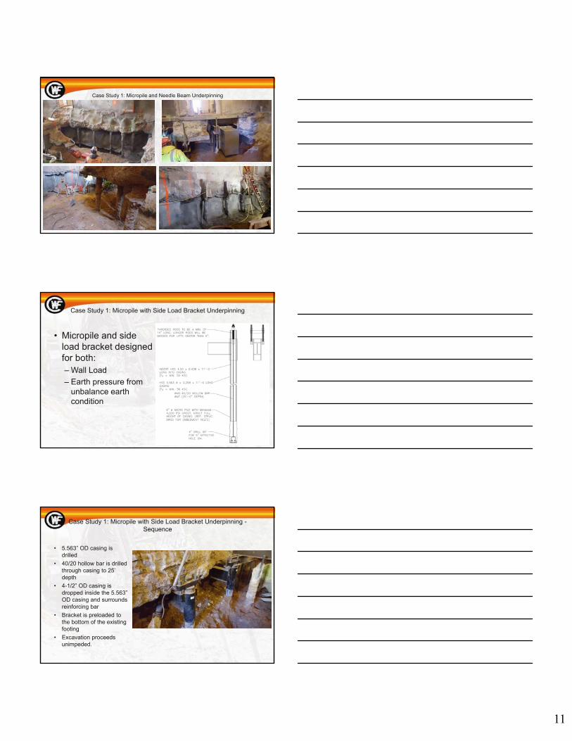
Case Study 1: Micropile with Side Load Bracket Underpinning
• Micropile and side load bracket designed for both:– Wall Load
– Earth pressure from unbalance earth condition
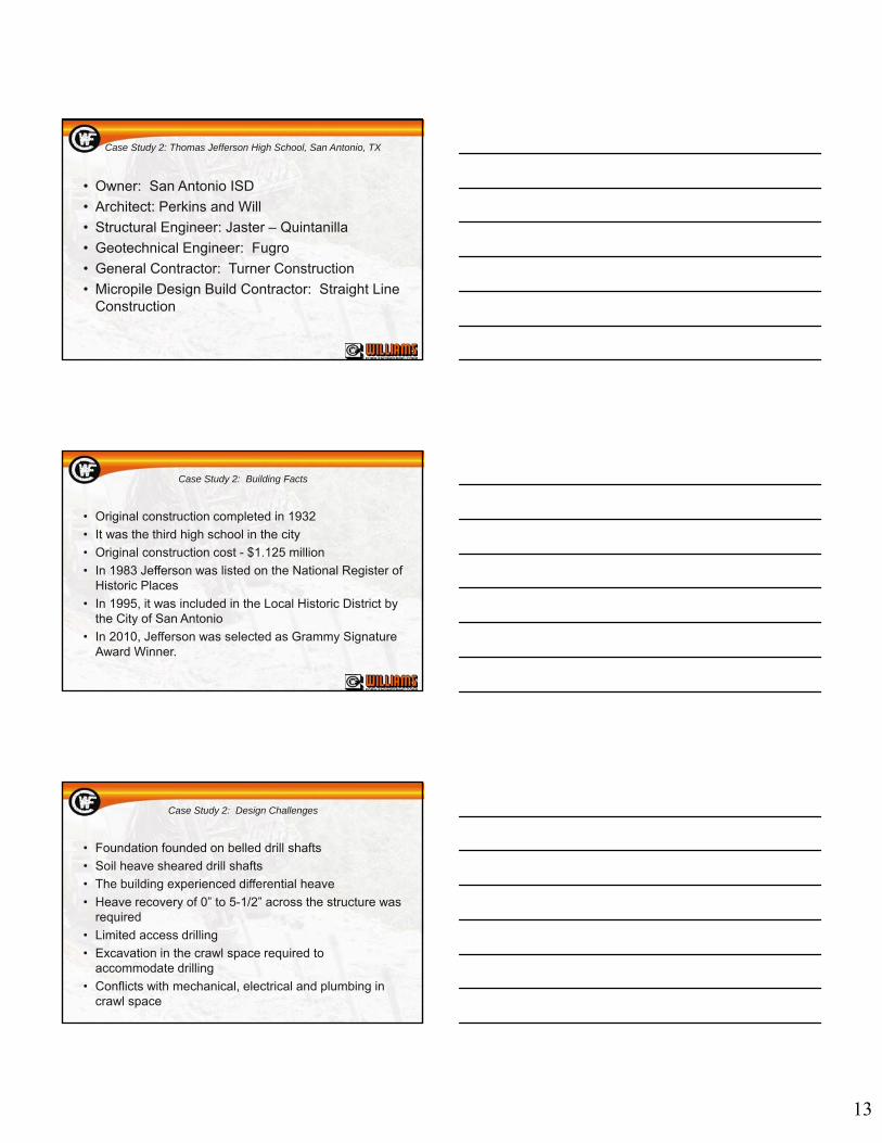
Case Study 1: Micropile with Side Load Bracket Underpinning -Sequence
• 5.563” OD casing is drilled
• 40/20 hollow bar is drilled through casing to 25’ depth
• 4-1/2” OD casing is dropped inside the 5.563” OD casing and surrounds reinforcing bar
• Bracket is preloaded to the bottom of the existing footing
• Excavation proceeds unimpeded.

12
Case Study 1: Micropile with Side Load Bracket - Preloaded
Case Study 1: Reticulated Micropiles
• Solution for Northwest and Southwest Mechanical rooms
• Access to outside of the building for needle beam construction was obstructed by scaffold
• Reticulated micropiles were designed for underpinning and earth retention
Case 1: Reticulated Micropiles
13
Case Study 2: Thomas Jefferson High School, San Antonio, TX
• Owner: San Antonio ISD
• Architect: Perkins and Will
• Structural Engineer: Jaster – Quintanilla
• Geotechnical Engineer: Fugro
• General Contractor: Turner Construction
• Micropile Design Build Contractor: Straight Line Construction
Case Study 2: Building Facts
• Original construction completed in 1932
• It was the third high school in the city
• Original construction cost - $1.125 million
• In 1983 Jefferson was listed on the National Register of Historic Places
• In 1995, it was included in the Local Historic District by the City of San Antonio
• In 2010, Jefferson was selected as Grammy Signature Award Winner.
Case Study 2: Design Challenges
• Foundation founded on belled drill shafts
• Soil heave sheared drill shafts
• The building experienced differential heave
• Heave recovery of 0” to 5-1/2” across the structure was required
• Limited access drilling
• Excavation in the crawl space required to accommodate drilling
• Conflicts with mechanical, electrical and plumbing in crawl space
14
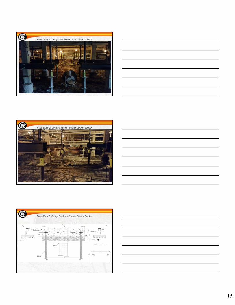
Case Study 2: Design Solution
• Micropile system that would incorporate temporary loading of existing column to cut away drilled shafts, as well as provide a permanent pier cap after lowering the column
Case Study 2: Design Solution – Interior Column Sequence
• Drill and install opposing piles with casing on each side of column
• Drill existing column, install thru-bolts and back to back channels
• Install manifold hydraulic jacking system from the top of the micropiles to the bottom of the back to back channels
• Using structural steel tubing, extend the line of action from the jacks to the bottom of the floor beam
• Apply building dead load while monitoring upward column movement
• Cut the bottom of the column from the drilled shaft
• Cut drilled shaft well below grade
• Lower the column to desired elevation
• Dowel column and tie into new pier cap concrete reinforcement
• Form and pour new cap
• Allow 7 day cure
• Remove back to back channels and jacking system for permanent loading condition
Case Study 2: Design Solution – Interior Column Solution
15
Case Study 2: Design Solution – Interior Column Solution
Case Study 2: Design Solution – Interior Column Solution
Case Study 2: Design Solution – Exterior Column Solution

16
Case Study 2: Design Solution – Exterior Column Solution
Case Study 2: Design Solution – Exterior Column Solution
www.williamsform.com
THE END