structural dynamic testing results for air …
TRANSCRIPT

1
STRUCTURAL DYNAMIC TESTING RESULTS FOR AIR-INDEPENDENT PROTON EXCHANGE MEMBRANE (PEM) FUEL CELL TECHNOLOGIES FOR SPACE
APPLICATIONS
Ryan P. Gilligan1, Ian J. Jakupca2, Phillip J. Smith, William R. Bennett, Monica C. Guzik, and
Henry Kacher NASA John H. Glenn Research Center
Cleveland, OH
ABSTRACT
In 2016, the National Aeronautics and Space Administration
(NASA) Advanced Exploration Systems (AES) project office
funded testing at the NASA Glenn Research Center to evaluate
the maturity of the Proton Exchange Membrane (PEM) fuel cell
technology and its viability for supporting launch vehicle and
space applications. This technology evaluation included
vibration, reactant purity, and vacuum exposure sensitivity
testing. The evaluation process did not include microgravity
testing. This paper discusses the vibration sensitivity testing of
two air-independent fuel cell stacks provided by different
vendors to assess the ability of currently available fuel cell stack hardware to survive the projected random vibrational
environment that would be encountered in an upper stage launch
vehicle. Baseline performance testing was utilized to quantify
stack performance and overboard leak rate at standard
atmospheric conditions in order to provide a reference for post-
test comparison. Both fuel cell stacks were tested at a random
vibration qualification level of 10.4 grms for five minutes in each
axis. Low-level sinusoidal sweeps were conducted before and
after each random vibration level run to see if any significant
change in resonances were detected. Following vibration
facility testing, the baseline performance testing was repeated.
Test results demonstrated no measurable change in fuel cell electrochemical or mechanical performance, indicating that the
two evaluated PEM fuel cell stacks may be suitable for space
applications pending microgravity testing.
ACRONYMS AES Advanced Exploration Systems
AMPS AES Modular Power Systems
CTB Common Test Bed
1 Contact author: [email protected] 2Contact author: [email protected]
grms Root mean square of acceleration load GRC Glenn Research Center
LVUS Launch Vehicle Upper Stage
NASA National Aeronautics and Space
Administration
PEM Proton Exchange Membrane
SDL Structural Dynamics Laboratory
TRL Technology Readiness Level
1. INTRODUCTION
Fuel cells are energy conversion devices that convert
chemical potential energy into electrical energy. Proton Exchange Membrane (PEM) fuel cells consume hydrogen and
oxygen gas to produce electricity, heat, and water. Trade studies
have indicated that PEM fuel cells provide a significant mass
benefit over battery systems traditionally used on the upper
stages of launch vehicles for mission durations longer than
several hours [1]. This trade is currently restricted to launch
vehicle upper stages (LVUSs) utilizing cryogenic hydrogen and
oxygen propellants because the propellant boil off which would
otherwise be wasted can be used as reactants for the fuel cell to
power the LVUS [2]. In addition to providing electrical power to
the upper stage vehicle, the waste heat produced can also help
maintain electronics within operational or survival temperature ranges.
Prior to incorporation into an upper stage design, further
work was needed to adapt the technology to meet typical launch
vehicle requirements. In 2016 the Advanced Exploration
Systems (AES) program office and NASA Glenn Research
Center (GRC) entered a partnership with an upper stage
developer to assess the PEM fuel cell technology. Together, the
AES Modular Power Systems (AMPS) project and the upper
2
stage developer created requirements and then tested subscale
hardware with extensibility to a launch vehicle upper stage
application. Subscale stack hardware testing focused on testing
existing state of the art fuel cell stacks in order to inform a final
design capable of meeting LVUS requirements. The testing approach reduced the risk associated with qualifying fuel cell
stack hardware for Technology Readiness Level (TRL) 6 in
anticipation of a near-term flight application. This paper focuses
on one of the key areas identified for risk reduction testing: a
vibration test of existing subscale fuel cell stacks at the expected
levels encountered during a LVUS flight.
A test series was conducted to assess the ability of currently
available air-independent fuel cell stack hardware to survive the
projected random vibrational environment that would be
encountered in a LVUS application. Air-independent fuel cell
stacks do not rely on ambient air for an oxidizer but instead
utilize a dedicated oxygen supply. Air independent stacks also have the ability to passively remove product water from the stack
without using power or rotating components [3]. Two vendors
provided NASA with one air-independent fuel cell stack each to
test. Infinity Fuel Cell and Hydrogen supplied a stack without a
vibration-isolation mount and Teledyne Energy Systems
delivered a single air-independent stack that included a vibration
dampening mount.
2. TEST PLAN
The test was segmented into 3 stages: baseline performance
testing of the fuel cell stacks, vibration facility testing, and post-
vibration comparative performance testing. Baseline
performance testing quantified stack electrochemical
performance when subjected to a standardized load profile and a
helium overboard leak rate at standard atmospheric conditions in
order to provide a reference for post-test comparison. Vibration
facility testing consisted of random vibration of the fuel cell stacks while pressurized with gaseous helium at the vendor-
specified operating pressure. Following vibration facility testing,
the baseline performance testing was repeated for a post-
vibration performance comparison.
Two metrics were used to measure success: stack pressure
decay rate and stack electrochemical performance. Stack
pressure decay rate is defined as the quantity of observed
pressure loss in the fuel cell stack (psid) over a ten minute period.
During stack pressure decay rate testing the initial helium
pressure was equal to the standard operating pressure defined for
the stack. Stack performance is defined as the power response to the NASA 2 Hour Load Profile test, as measured by mapping
the average cell voltage (V) against the current density
(mA/cm2).
Success for both metrics was determined by comparing the
post-vibration comparative performance testing data to the
baseline performance testing data. The success criteria tolerance
was ±10% variance between baseline and post vibration test data
for both the stack performance and pressure decay rate metrics.
Fuel cell stack performance is dependent on stack temperature
and reactant pressures. An uncertainty analysis was performed to
evaluate these relations. The acceptance range incorporates
experimental error due to pressure and temperature control
precision limits within the test apparatus.
In addition to the pressure decay and electrochemical
performance metrics, visual inspections of hardware were conducted to check for major structural anomalies during
vibration testing. Sinusoidal sweeps at 0.25 grms peak amplitude
were also conducted before and after each vibration test to
determine if non-visible structural anomalies occurred via major
shifts in resonant frequencies. A 5% variability in resonance
frequency shift was deemed acceptable by the project due to
uncertainty associated with the test instrumentation and
variability in the experimental setup. However, this metric for
resonance response was not a concrete pass or fail evaluation.
2.1 Baseline Performance Testing
Baseline performance testing was conducted at the fuel cell
test laboratory at NASA GRC. Testing consisted of measuring
each fuel cell stack performance during the NASA 2 Hour Load
Profile test and measuring stack pressure decay rate prior to
vibration facility testing. The NASA 2 Hour Load Profile is an
electrical load profile applied to a fuel cell stack that was
developed during the Reusable Launch Vehicle program based
on a Space Shuttle Orbiter mission. The load is scaled with the
active area of the fuel cell stack so that the performance of fuel
cells with differing active areas can be directly compared. Figure
1 shows the NASA 2 Hour Load Profile. A polarization curve is used to characterize fuel cell stack performance before and after
the 2 Hour Load Profile. The Load Profile test reports the
measured average cell voltage response to the stack current
density demanded by the electrical load profile.
Fuel cell orientation and inlet pressure sensitivity testing
were also performed as part of the LVUS application testing. For
the purposes of generating baseline data prior to vibration
testing, however, the fuel cell stack was tested in the standard
orientation, with reactant delivery at the standard operating
pressure for the stack as defined by each fuel cell vendor. Each
NASA 2 Hour Load Profile test was performed at least three
times for repeatability. The average response of the fuel cell stack is reported. This result is referred to as the Baseline Stack
Performance.
Stack pressure decay rate is reported as the observed drop in
pressure from its initial conditions at standard operating pressure
over a ten minute period when the fuel cell stack is pressurized
with gaseous helium. The ambient environment was at standard
atmospheric conditions. This pressure decay rate test was
performed three times for repeatability, and the average pressure
decay rate is reported, with appropriate margins of error. This
result is referred to as the Baseline Stack Pressure Decay Rate.

3
Figure 1. NASA 2 HOUR LOAD PROFILE.
2.2 Vibration Facility Testing
After the completion of baseline performance testing, the
fuel cell stacks were relocated to the NASA GRC Structural Dynamics Laboratory (SDL) and readied for random vibration
testing. A vibration mounting fixture was designed for the fuel
cell stack provided by Infinity. The fuel cell was hard mounted
to one end of the fixture and secured by a slide pin on the
opposite side of the fixture. The fuel cell stack was oriented
horizontally with both anode and cathode endplates oriented
perpendicular to the vibration table surface. The fuel cell stack
from Infinity was tested in 3 axes utilizing a 24 in. by 24 in. MB
Dynamics C-60 shaker table. Figure 2 illustrates the orientation
of each axis of the fuel cell relative to the vibration direction.
Vibration testing occurred while the fuel cells were in a non-operative (inert) state and pressurized with gaseous helium at
standard operating pressure.
Figure 2. ORIENTATION OF INFINITY FUEL CELL STACK
DURING VIBRATION TESTING.
Two control accelerometers were mounted on opposite sides
of the mounting fixture for all vibration testing. One triaxial and
one single axis response accelerometer were located on the endplates of the fuel cell. The triaxial response was located on
the endplate closer to the hard mounted side of the fuel cell while
the single axis response was located on the endplate on the
pinned end. Both were used to collect vibration level data of the
fuel cell. The single axis accelerometer was rotated into the
direction of motion for each axis. A triaxial accelerometer was
located at the center of the 3 mounting screws on the mounting
bracket and a reference accelerometer was located at the base of
a hard mount L-bracket that secured the fixture to the shaker
table. The vibration inputs were controlled by the average of the
two control accelerometer signals. Figure 3 shows the stack
mounted on the test fixture and the location of some of these accelerometers denoted M3X, M7X, M8Y, M9Z, and M10X.
Figure 3. INFINITY FUEL CELL STACK MOUNTED ON
SHAKER TABLE FOR TESTING IN X-AXIS.
Teledyne delivered a fuel cell to NASA with an integrated
mounting fixture. The vendor test fixture was bolted to a 12 in.
by 7 in. fixture plate. Figure 4 illustrates the orientation of each
axis of the Teledyne fuel cell relative to the vibration direction.
The fixture plate was mounted to a 24 in. by 24 in. MB Dynamics
C-60 shaker table for vibration testing in the X- and Y-axes. For
testing in the Z direction the fixture plate was mounted to a LingElectronics 4022 shaker table with a 24 in. diameter mounting
plate.
Figure 4. ORIENTATION OF TELEDYNE FUEL CELL
STACK ON BOTH VIBRATION TABLES.
Two control accelerometers were mounted on opposite sides
of the 12 in. by 7 in. fixture plate for all vibration testing. One
triaxial and one single axis response accelerometer were located
on the top corners of the fuel cell endplates. The triaxial
response was located on a side of the fuel cell stack that had Belleville washers while the single axis response was located on
the opposite side from the Belleville washers. Both were used to
collect vibration level data of the fuel cell. The single axis
accelerometer was rotated into the direction of motion for each
axis. In addition a single axis reference accelerometer was
located at the base of the hard mount L-bracket and was also
rotated into the direction of motion for each axis. The vibration
inputs were controlled by the average of the two control
accelerometer signals.

4
Sinusoidal and qualification level random vibration tests
were conducted per program requirements on stacks from both
vendors in all 3 axes. Prior to a vibration test the stacks were
pressurized with gaseous helium to their standard operating
pressure and a pressure decay rate was measured. If the stack pressure decay rate did not match baseline measurements, a leak
check of the helium supply system fittings was performed and
the measurement was repeated. After an initial pressure decay
measurement a sinusoidal sweep of each fuel cell was performed
to determine the resonant frequencies of the hardware. The
sinusoidal level used was 0.25 grms peak from 5 to 2000 Hz at a
sweep rate of 2 octaves/minute. After the sinusoidal sweep the
fuel cells were tested at an applicable LVUS acceptance level
twice in a single axis. A third run at representative LVUS
qualification levels was then performed. The qualification
random vibration level used was 10 grms for five minutes duration
in each axis. The helium pressure in the fuel cell was recorded during sine sweeps, acceptance level, and qualification level
testing. A post qualification level sinusoidal sweep was
performed to check for significant changes in resonant
frequencies. A final pressure decay test was then conducted
prior to removing each fuel cell from the shaker table and
preparing for the next test.
2.3 Post Vibration Comparative Performance Testing
The electrochemical performance testing using the NASA 2
Hour Load Profile and pressure decay testing described in Section 2.1 were repeated after testing at the SDL. The pre-
vibration and post-vibration data were then compared to
determine if the success criteria for the test series was met.
3. RESULTS AND DISCUSSION
3.1 Infinity Fuel Cell Stack Vibration Testing Results
The X-axis vibration test results for the stack provided by
Infinity are displayed in Figure 5 through Figure 7 based on the
respective orientations illustrated in Figure 3. The control accelerometers ensured an excitation at the base of the test
fixture to be at the required test levels. It was found during
testing that the vibration fixture had resonances within the test’s
frequency range and amplified the excitation at these
frequencies. This caused the actual hardware to see levels of
15.2 grms at the fuel cell end plate with pin support and 16.9 grms
at the endplate fixed to the support as evidenced by the response
accelerometers M10X and M7X, respectively. Testing in the x
axis showed a 22.3 Hz variation in peak resonant frequency
between pre- and post-qualification testing. This equates to a
4.1% variance, which is within the 5% uncertainty limit of the test apparatus and experimental setup. No visible structural
anomalies were observed during X-axis testing.
Figure 5. INFINITY X-AXIS QUALIFICATION LEVEL
VIBRATION TEST RESULTS.
Figure 6. INFINITY PRE-QUALIFICATION TEST X AXIS
SINE SWEEP.
Figure 7. INFINITY POST-QUALIFICATION TEST X AXIS
SINE SWEEP.
5 200010 100 10000.004
3.000
0.010
0.100
1.000
Frequency (Hz)
Accele
ration (
G p
eak)
Acceleration Profile
Demand
M7X
M10X
Frequency 541.4 Hz
Demand 0.25 G
M7X 2.184 G
M10X 1.811 G
5 200010 100 10000.003
4.000
0.010
0.100
1.000
Frequency (Hz)
Accele
ration (
G p
eak)
Acceleration Profile
Demand
M7X
M10X
Frequency 519.1 Hz
Demand 0.25 G
M7X 3.33 G
M10X 2.787 G

5
Figure 8. INFINITY FUEL CELL STACK MOUNTED ON
SHAKER TABLE FOR TESTING IN Y-AXIS.
Figure 8 shows the Infinity stack orientation on the shaker
table for testing in the Y-axis. The Y-axis vibration test results
are displayed in Figure 9 through Figure 11. The vibration fixture
had resonances within the test’s frequency range and amplified
the excitation at these frequencies. This caused the actual
hardware to see levels of 41.2 grms at the fuel cell end plate with
pin support and 25.0 grms at the endplate fixed to the support as
evidenced by the response accelerometers M10Y and M8Y, respectively. Testing in the Y-axis showed a 6.6 Hz variation in
peak resonant frequency between pre- and post-qualification
testing. This equates to a 1.8% variance, which is within the 5%
uncertainty limit determined by the project. At the conclusion of
Test Day 1, the fuel cell stack was to be rotated on its mount pin
to be re-oriented for Z-axis testing. During this maneuver, it was
discovered that the mount pin had been scored as shown in
Figure 12 such that it would no longer move freely within the
fixture mounting collar. The mount pin was freed and machined
to smooth its surfaces. The mounting fixture was then
reassembled on Test Day 2 to begin Z-axis testing.
Figure 9. INFINITY STACK Y-AXIS QUALIFICATION
LEVEL VIBRATION TEST RESULTS.
Figure 10. INFINITY FUEL CELL STACK PRE-
QUALIFICATION TEST Y-AXIS SINE SWEEP.
Figure 11. INFINITY FUEL CELL STACK POST-
QUALIFICATION TEST Y-AXIS SINE SWEEP.
Figure 12. SCORED MOUNTING PIN DISCOVERED WHEN
PREPARING FOR INFINITY STACK Z-AXIS VIBRATION
TESTING.
5 200010 100 1000
8.00
0.01
0.10
1.00
Frequency (Hz)
Accele
ration (
G p
eak)
Acceleration Profile
Demand
M8Y
M10Y
Frequency 374.4 Hz
Demand 0.25 G
M8Y 3.899 G
M10Y 6.611 G
5 200010 100 10000.03
8.00
0.10
1.00
Frequency (Hz)
Accele
ration (
G p
eak)
Acceleration Profile
Demand
M8Y
M10Y
Frequency 367.8 Hz
Demand 0.25 G
M8Y 4.617 G
M10Y 7.431 G

6
The Z-axis vibration test results are displayed in Figure 13
through Figure 15. The control accelerometers ensured an
excitation at the base of the test fixture to be at the required test
levels. The vibration fixture had resonances within the test’s
frequency range, which caused the actual hardware to see levels of 25.1 grms at the fuel cell end plate with pin support as
evidenced by the response accelerometer M10Z. The
accelerometer on the fixed end of the support was not
functioning during this test. Testing in the Z-axis showed a 6.3
Hz variation in peak resonant frequency between pre- and post-
qualification testing. This equates to a 1.5% variance, which is
within the 5% uncertainty limit. No visible structural anomalies
were observed during Z-axis testing.
During the Z-axis testing, it was noted that the resonant peak
frequency was approximately 46 Hz (~12%) different than that
encountered in Y-axis testing. To eliminate the mount pin issue
as a cause for a significant resonant frequency shift, Y-axis testing was repeated at a lower random vibration level to avoid
unnecessarily stressing the stack. The low level sinusoidal
sweeps were also repeated before and after the lower random
vibration level test. The Y-axis resonant peak frequency prior to
each Y-axis vibration was shown to be within 1.5%, suggesting
the change in frequency between the Z-axes in Figure 14 and
Figure 15 and Y-axes in Figure 10 and Figure 11 is due to
geometry differences rather than the mount pin.
Figure 13. INFINITY STACK Z-AXIS QUALIFICATION
LEVEL VIBRATION TEST RESULTS.
Figure 14. INFINITY STACK PRE-QUALIFICATION TEST
Y-AXIS SINE SWEEP.
Figure 15. INFINITY STACK POST-QUALIFICATION
TEST Y-AXIS SINE SWEEP.
3.2 Teledyne Vibration Testing Results
The Teledyne X-axis vibration test results are displayed in
Figure 16 through Figure 18. Figure 19 shows the orientation of
the fuel cell stack on the shaker table for the X-axis test. The
control accelerometers ensured an excitation at the base of the test fixture to be at the required 10.4 grms. During testing the
vibration fixture had resonances within the test’s frequency
range and amplified the excitation at these frequencies. The fuel
cell endplate on the Belleville washer side experienced a 19.5
grms load and the endplate with the fluidic interfaces experienced
a 17.2 grms peak load as indicated by the M5X and M7X tagged
accelerometers, respectively. Testing in the X-axis showed a 10
Hz variation in the first mode resonant frequency between pre-
and post-qualification testing. This equates to a 4.1% variance,
which is within the 5% uncertainty limit determined by the
project.
5 200010 100 1000
0.0010
0.0100
0.1000
1.0000
Frequency (Hz)
Accele
ration (
G p
eak)
Acceleration Profile
Demand
M9Z
M10Z
Frequency 420.9 Hz
Demand 0.25 G
M9Z 0.02924 G
M10Z 3.912 G
5 200010 100 1000
0.0010
0.0100
0.1000
1.0000
Frequency (Hz)
Accele
ration (
G p
eak)
Acceleration Profile
Demand
M9Z
M10Z
Frequency 414.6 Hz
Demand 0.25 G
M9Z 0.03988 G
M10Z 5.067 G

7
Figure 16. TELEDYNE X-AXIS QUALIFICATION LEVEL
VIBRATION TEST RESULTS.
Figure 17. TELEDYNE PRE-QUALIFICATION TEST X-
AXIS SINE SWEEP.
Figure 18. TELEDYNE POST QUALIFICATION TEST X-
AXIS SINE SWEEP.
Figure 19. TELEDYNE FUEL CELL STACK MOUNTED ON
MB C-60 SHAKER TABLE FOR TESTING IN Y-AXIS.
Figure 19 shows the Teledyne stack orientation on the
shaker table for testing in the Y-axis. The Y-axis vibration test
results are displayed in Figure 20 through Figure 22. The
vibration fixture had resonances within the test’s frequency
range and amplified the excitation at these frequencies. The fuel
cell endplate on the Belleville washer side experienced a 21.5
grms load and the endplate with the fluidic interfaces experienced
an 18.5 grms peak load as indicated by the M5X and M7X tagged accelerometers, respectively. Testing in the Y-axis showed a 33
Hz variation in the first mode resonant frequency between pre-
and post-qualification testing. This equates to a 7.5% variance,
which is outside the 5% uncertainty limit. However, this
response is similar to previously tested hardware at the SDL that
used Belleville washers as the primary sealing method and was
determined not to be a concern. No visible structural anomalies
were observed during Y-axis testing.
Figure 20. TELEDYNE Y-AXIS QUALIFICATION LEVEL
VIBRATION TEST RESULTS.
5 200010 100 10000.02
5.00
0.10
1.00
Frequency (Hz)
Accele
ration (
G p
eak)
Acceleration Profile
Demand
M5X
M7X
Frequency 251.3 Hz
Demand 0.25 G
Control Hi 0.2571 G
Control Lo 0.2503 G
M5X 3.425 G
M7X 3.171 G
Frequency 459.1 Hz
Demand 0.25 G
Control Hi 0.2567 G
Control Lo 0.2511 G
M5X 1.255 G
M7X 0.2718 G
Frequency 519.1 Hz
Demand 0.25 G
Control Hi 0.2547 G
Control Lo 0.2502 G
M5X 0.4228 G
M7X 1.015 G
5 200010 100 10000.02
5.00
0.10
1.00
Frequency (Hz)
Accele
ration (
G p
eak)
Acceleration Profile
Demand
Control
M5X
M7X
Frequency 241 Hz
Demand 0.25 G
Control 0.2527 G
M5X 3.42 G
M7X 3.2 G
Frequency 406 Hz
Demand 0.25 G
Control 0.2602 G
M5X 1.146 G
M7X 0.722 G
Frequency 508.3 Hz
Demand 0.25 G
Control 0.2593 G
M5X 0.8445 G
M7X 0.2851 G
20 2000100 1000
-32x10
03x10
-21x10
-11x10
01x10
Frequency (Hz)
Accele
ration S
pectr
al D
ensity (
G²/
Hz)
Acceleration Spectral Density
Demand
M4Y
M7Y
Frequency 20 - 2000 Hz
Demand 10.36 G RMS
M4Y 21.51 G RMS
M7Y 18.52 G RMS

8
Figure 21. TELEDYNE PRE-QUALIFICATION TEST Y-
AXIS SINE SWEEP.
Figure 22. TELEDYNE POST-QUALIFICATION TEST Y-
AXIS SINE SWEEP.
Figure 23. TELEDYNE FUEL CELL STACK MOUNTED ON
LING 4022 SHAKER TABLE FOR TESTING IN Z-AXIS.
Figure 23 shows the Teledyne fuel cell stack mounted on the
vertical shaker table for testing in the Z-axis. The Z-axis
vibration test results are displayed in Figure 24 through Figure
26. The vibration fixture had resonances within the test’s
frequency range and amplified the excitation at thesefrequencies. The fuel cell endplate on the side with the Belleville
washers experienced a 15.3 grms load as indicated by the M7Z
tagged accelerometer. Testing in the Z-axis showed a 7 Hz
variation in the first mode peak resonant frequency between pre-
and post-qualification testing. This equates to a 2.6% variance,
which is within the 5% uncertainty limit.
In future vibration testing, vibration fixtures should be
designed to not have resonances within the test frequency.
Alternatively, the control accelerometers could be located closer
to the hardware-fixture interface to avoid hardware vibrational
levels exceeding control levels.
Figure 24. TELEDYNE Z-AXIS QUALIFICATION LEVEL
VIBRATION TEST RESULTS.
Figure 25. TELEDYNE PRE-QUALIFICATION TEST Z-
AXIS SINE SWEEP.
5 200010 100 10000.03
5.00
0.10
1.00
Frequency (Hz)
Accele
ration (
G p
eak)
Acceleration Profile
Demand
Control
M4Y
M7Y
Frequency 441.6 Hz
Demand 0.25 G
Control 0.2563 G
M4Y 1.418 G
M7Y 0.6343 G
Frequency 508.3 Hz
Demand 0.25 G
Control 0.2546 G
M4Y 1.643 G
M7Y 0.7793 G
Frequency 735 Hz
Demand 0.25 G
Control 0.2586 G
M4Y 1.925 G
M7Y 1.126 G
5 200010 100 10000.02
5.00
0.10
1.00
Frequency (Hz)
Accele
ration (
G p
eak)
Acceleration Profile
Demand
M4Y
M7Y
Frequency 408.5 Hz
Demand 0.25 G
Control Hi 0.2558 G
Control Lo 0.2443 G
M4Y 1.3 G
M7Y 0.6368 G
Frequency 464.6 Hz
Demand 0.25 G
Control Hi 0.2631 G
Control Lo 0.2425 G
M4Y 2.062 G
M7Y 0.8599 G
Frequency 523.8 Hz
Demand 0.25 G
Control Hi 0.2647 G
Control Lo 0.2555 G
M4Y 1.784 G
M7Y 0.5174 G
Frequency 673.8 Hz
Demand 0.25 G
Control Hi 0.2571 G
Control Lo 0.2521 G
M4Y 1.366 G
M7Y 0.7685 G
20 2000100 1000
-32x10
02x10
-21x10
-11x10
01x10
Frequency (Hz)
Accele
ration S
pectr
al D
ensity (
G²/
Hz)
Acceleration Spectral Density
Demand
C1
M6Z
M7Z
Frequency 20 - 2000 Hz
Demand 10.36 G RMS
C1 10.39 G RMS
M6Z 8.325 G RMS
M7Z 15.29 G RMS
5 200010 100 1000
5.000
0.010
0.100
1.000
Frequency (Hz)
Accele
ration (
G p
eak)
Acceleration Profile
Demand
Control
M6Z
M7Z
Frequency 263.7 Hz
Demand 0.25 G
Control 0.2492 G
M6Z 0.4337 G
M7Z 0.2569 G
Frequency 1209 Hz
Demand 0.25 G
Control 0.249 G
M6Z 0.8307 G
M7Z 2.829 G

9
Figure 26. TELEDYNE POST-QUALIFICATION TEST Z-
AXIS SINE SWEEP.
3.3 Infinity Pressure Decay Test Summary
Figure 27 shows the measured pressure decay of the
Infinity stack during the Y-axis qualification testing. The stack
was pressurized to 30 ±1 psig with helium which is
representative of the nominal stack operating pressure. The
hydrogen, oxygen, and product water passages were all at a
balanced pressure. The orange highlighted part of curve,
beginning at 8 minutes in Figure 27 is when the qualification
levels are reached. The measured leak rate test includes the fuel cell stack and all plumbing and flex hoses to an isolation valve
downstream the supply pressure regulator as illustrated in Figure
28. The pressure decay rate prior to the 10 grms load is 0.054
psi/minute. The pressure decay rate during the 10 grms load is
0.044 psi/minute. Note the temporary reduction in pressure
decay rate during vibration testing at 10 grms. The likely cause of
this is that the mechanical energy put into the fuel cell from the
shaker table may have increased the temperature of the gas which
would result in an increase in pressure and thus giving the
appearance of a reduction in leak rate. After the vibration test the
pressure decay rate returned to 0.044 psi/minute.
Figure 27. INFINITY STACK PRESSURE DECAY DURING
Y-AXIS QUALIFICATION TEST.
Figure 28. HELIUM SUPPLY CONFIGURATION
DURING VIBRATION TESTING OF INFINITY
STACK.
Figure 29 displays the Infinity stack pressure as a
function of time during Y-axis vibration testing. The leak rate is
consistent over all the Y-axis vibration tests at 0.050 psi/minute.
This leak rate is also consistent with the Baseline Stack Pressure
Decay Rate. Similar results were observed for X-axis and Z-axis
testing. The transfer of fluidic lines resulted in some variability
between trials but the average leak rate was consistently within
±10% of 0.050 psi/minute for all tests, satisfying the success
criteria identified by the project.
Figure 29. PRESSURE DECAY RATES DURING Y-AXIS
VIBRATION TESTING FOR INFINITY FUEL CELL
STACK.
3.3 Teledyne Pressure Decay Test Summary
Figure 30 shows the pressure decay of the Teledyne stack
during the Y-axis qualification level vibration testing. The stack
was pressurized to 6 ± 1 psig with helium with the hydrogen,
oxygen, and product water passages all at a balanced pressure.
This pressure is representative of the stack nominal operating
5 200010 100 10000.005
5.000
0.010
0.100
1.000
Frequency (Hz)
Accele
ration (
G p
eak)
Acceleration Profile
Demand
Control
M6Z
M7Z
Frequency 256.7 Hz
Demand 0.25 G
Control 0.2491 G
M6Z 0.4776 G
M7Z 0.2541 G
Frequency 1194 Hz
Demand 0.25 G
Control 0.2539 G
M6Z 0.9059 G
M7Z 2.412 G
29.4
29.6
29.8
30
30.2
30.4
30.6
0 5 10 15 20
Sta
ck P
ress
ure
, psi
g
Test Time, minutes
29.4
29.6
29.8
30
30.2
30.4
30.6
0 5 10 15 20
Sta
ck P
ress
ure
, p
sig
Test Time, minutes
sine sweep #1
10 grms Qual Test
sine sweep #2
5 grms Accept Test
start 10 grms
end 10 grms

10
pressure. The pressure was monitored before, during, and after
each vibration trial to establish a leak rate.
The leak rate test includes the fuel cell stack and all
plumbing and flexible hoses from an isolation ball valve. No
increase in pressure decay rate was observed over the baseline rate. In fact, there was a temporary reduction in pressure decay
during vibration testing at 10.4 grms. The mechanism is likely the
same as for the Infinity fuel cell stack. The temperature of the
helium and any residual water may have increased from the
vibrational energy load on the stack which would increase the
pressure within the stack.
Figure 30. TELEDYNE STACK PRESSURE DECAY
DURING Y-AXIS QUALIFICATION TEST.
The pressure decay rate is consistent over all the Y-axis vibration tests. The pressure decay rate is also consistent with the
Baseline Stack Pressure Decay rate. Similar results were
observed for X-axis and Z-axis testing. The transfer of plumbing
lines resulted in some variability between trials but the average
leak rate was consistently within ±10% of 0.021 psi/minute for
all tests.
3.4 Infinity Electrochemical Performance Test Summary
A NASA GRC’s Common Test Bed (CTB) was utilized to perform operational testing of the fuel cell stack [4]. Once the
fuel cell stack had reached full operational temperature, the
NASA 2 Hour Load Profile test from Figure 1 was initiated. Fuel
cell stack performance is measured by each cell’s voltage for a
given current density. The Infinity stack contained 12 cells at 50
cm2 active area per cell. Taking the average voltage of all the
cells yields a representative cell voltage for a given current
density. Figure 31 shows the average difference between the
average cell potential before and after vibration testing. Fuel cell
measurement variability is ± 8 mV due to changes in pressure
and temperature during testing. Although the difference in
average cell potential slightly exceeds this value at high current
densities, it can still be concluded that there is no meaningful
change in performance resulting from exposure to vibration. As
is illustrated in Figure 31, the percent deviation in average cell
voltages for Baseline and Post-Vibration testing was below 1.5% for all current densities, satisfying the ±10% success criteria
determined by the project.
Figure 31. ELECTROCHEMICAL PERFORMANCE
DIFFERENCE FROM BASELINE TESTING TO POST-
VIBRATION TESTING FOR INFINITY STACK.
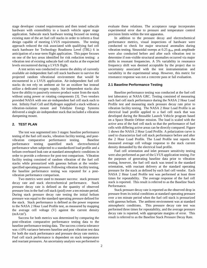
3.5 Teledyne Electrochemical Performance Test Summary
One of NASA GRC’s CTB was modified to accommodate
the flow-through nature of the Teledyne fuel cell and this
modified CTB was utilized to perform operational testing of the
Teledyne stack. Once the fuel cell stack had reached an
operational temperature, the NASA 2 Hour Load Profile test from Figure 1 was initiated. The Teledyne stack contained 10
cells at 77 cm2 active area per cell. Figure 32 shows the average
difference between the average cell potential before and after
vibration testing. Similar to the Infinity results, the difference in
average cell potential slightly exceeds the 8 mV uncertainty
value at high current densities. This is not a significant change in
performance resulting from exposure to vibration. As is
illustrated in Figure 32, the percent deviation in average cell
voltages for Baseline and Post-Vibration testing for the Teledyne
fuel cell stack was below 1.2% for all current densities, satisfying
the ±10% success criteria determined by the project.
5.7
5.8
5.9
6.0
6.1
6.2
0 10 20 30 40
Pre
ssu
re, p
sig
Time elapsed (minutes)
0.25 grms
0.25 grms
10 grms
0.021 psi/min.
0.020 psi/min.
0.020 psi/min.
0.017 psi/min.
0.021 psi/min.
-1.5%
-1.0%
-0.5%
0.0%
0.5%
1.0%
-15
-10
-5
0
5
10
0 100 200 300 400 500
Sta
nd
ard
Dev
iati
on
in
Aver
age
Cel
l P
ote
nti
al, %
Aver
age
Cel
l P
ote
nti
al C
han
ge,
Δm
VCurrent Density, mA/cm2
Avg Cell VoltageStandard Deviation
11
Figure 32. ELECTROCHEMICAL PERFORMANCE
DIFFERENCE FROM BASELINE TESTING TO POST-
VIBRATION TESTING FOR TELEDYNE STACK.
4. CONCLUSION
Qualification random vibration testing at 10.4 grms for
five minutes in each axis was successfully completed on
air-independent fuel cell stacks from Infinity Fuel Cell and
Hydrogen, Inc. and Teledyne Energy Systems, Inc. No
structural anomalies were observed on either test unit for
any of the axes of vibration during these qualification level
tests. Performance results were within the required
program specifications both before and after the vibration
test at qualification levels with no significant change observed. Pressure decay rates for both fuel cell stacks had
less than 10% variation in Baseline and Post-Vibration
measurements, satisfying the success criteria for this
metric. The deviation in average cell potential from
Baseline testing to Post-Vibration testing was below 2%
for both fuel cell stacks for all current densities tested. The
fuel cell stacks successfully passed all test criteria for
vibration testing at representative LVUS qualification
levels.
ACKNOWLEDGEMENTS Joseph Ursic, Trevor Jones, James Winkel, and Vicente
Suarez - NASA GRC Structural Dynamics Laboratory.
William Smith – Infinity Fuel Cell and Hydrogen.
Robert Utz – Teledyne Energy Systems.
REFERENCES [1] Jakupca, I., Bennett, W., Smith, P., and Burke, K. “Fuel
Cell Research and Development for Earth and Space
Applications.” Department of Energy Annual Merit Review. June 2018.
[2] Polsgrove, T., Button, R., Linne, D. “Altair Lunar
Lander Consumables Management.” AIAA Space 2009
Conference and Exposition. September 2009.
[3] Hoberecht, M. and Jakupca, I. “Development Status ofPEM Non-Flow-Through Fuel Cell System Technology for
NASA Applications.” NASA TM 2011-217107.
[4] Manzo, Michelle. “NASA Glenn Research Center
Electrochemistry Branch Overview.” NASA Energy Storage
Workshop. July 2010.
-1.4%
-1.2%
-1.0%
-0.8%
-0.6%
-0.4%
-0.2%
0.0%
-10-9-8-7-6-5-4-3-2-10
0 200 400 600
Sta
ndar
d D
evia
tion
in
Aver
age
Cel
l P
ote
nti
al, %
Aver
age
Cel
l P
ote
nti
al C
han
ge,
∆m
V
Current Density, mA/cm2
Cell Potential Change
Standard Deviation