structural durability validation of bearing girders in...
TRANSCRIPT

Available online at www.sciencedirect.com
Engineering Failure Analysis 15 (2008) 247–260
www.elsevier.com/locate/engfailanal
Review
Structural durability validation of bearing girdersin marine Diesel engines
Vatroslav Grubisic a,1, Nenad Vulic b,*, Samuel Sonnichsen c,2
a Technical Consulting, Zum Stetteritz 1, D-64354 Reinheim, Germanyb Croatian Register of Shipping, Marasoviceva 67, HR-21000 Split, Croatia
c Wartsila Switzerland Ltd., P.O. Box 414, Zurcherstraße 12, CH-8401 Winterthur, Switzerland
Received 4 December 2006; accepted 7 January 2007Available online 27 January 2007
Abstract
The aim is to present the state-of-the-art methodology for structural durability evaluation of marine Diesel enginesbearing girders and to describe the responsibility of engine designers, manufacturers and system suppliers. A real exampleof several engines of the same type, where fatigue cracks arose in certain areas of their bearing girders, has been presented.The extensive investigation revealed the cause of the damage. The proper design was proved by properly implementedstate-of-the-art design methods and by experimental verification of calculations in two ships. Quality and test specificationsprescribed by the licensor have been found correct. It is concluded that the damage cause was the impermissible quality ofworldwide manufacture and improper production repair welding during manufacture.� 2007 Elsevier Ltd. All rights reserved.
Keywords: Marine Diesel engines; Bearing girders; Fatigue strength; Design; Manufacturing
Contents
1
d
S
1. Introduction . . . . . . . . . . . . . . . . . . . . . . . . . . . . . . . . . . . . . . . . . . . . . . . . . . . . . . . . . . . . . . . . . . . . . 2482. Responsibilities of the engine designers and the manufacturers. . . . . . . . . . . . . . . . . . . . . . . . . . . . . . . . . . 2503. Design procedures for general machinery components. . . . . . . . . . . . . . . . . . . . . . . . . . . . . . . . . . . . . . . . 2514. A state-of-the art design procedure for the bearing girders . . . . . . . . . . . . . . . . . . . . . . . . . . . . . . . . . . . . 252
350-6
oi:10.
* CoE-m
onnic1 Tel2 Tel
4.1. Determination of the bearing loads . . . . . . . . . . . . . . . . . . . . . . . . . . . . . . . . . . . . . . . . . . . . . . . . . 2524.2. Calculation of the stresses . . . . . . . . . . . . . . . . . . . . . . . . . . . . . . . . . . . . . . . . . . . . . . . . . . . . . . . . 2534.3. Assessment of the bearing girders fatigue strength . . . . . . . . . . . . . . . . . . . . . . . . . . . . . . . . . . . . . . 254
5. Validation of bearing girders design by experiments . . . . . . . . . . . . . . . . . . . . . . . . . . . . . . . . . . . . . . . . . 255
307/$ - see front matter � 2007 Elsevier Ltd. All rights reserved.
1016/j.engfailanal.2007.01.014
rresponding author. Tel.: +385 21 408 163; fax: +385 21 358 159.ail addresses: [email protected] (V. Grubisic), [email protected] (N. Vulic), [email protected] (S.
hsen)..: +49 6162 914 572; fax: +49 6162 914 573..: +41 52 262 4989; fax: +41 52 262 0725.
248 V. Grubisic et al. / Engineering Failure Analysis 15 (2008) 247–260
6. Manufacturing of bearing girders and production repair welding . . . . . . . . . . . . . . . . . . . . . . . . . . . . . . . . 2557. Example . . . . . . . . . . . . . . . . . . . . . . . . . . . . . . . . . . . . . . . . . . . . . . . . . . . . . . . . . . . . . . . . . . . . . . . . 2568. Discussion of the obtained results . . . . . . . . . . . . . . . . . . . . . . . . . . . . . . . . . . . . . . . . . . . . . . . . . . . . . . 2589. Conclusion . . . . . . . . . . . . . . . . . . . . . . . . . . . . . . . . . . . . . . . . . . . . . . . . . . . . . . . . . . . . . . . . . . . . . . 259
References. . . . . . . . . . . . . . . . . . . . . . . . . . . . . . . . . . . . . . . . . . . . . . . . . . . . . . . . . . . . . . . . . . . . . . . 259
1. Introduction
From the functional and the safety aspect, modern merchant ships are strongly dependent on the primemovers in their propulsion systems, regardless of their concept. The essential propulsion system conceptmay be based upon marine turbines, or a single- or multi-Diesel engines installation. Diesel engines are com-monly used today. It is always important to understand their functional role (class related), as well as thesafety aspects of their implementation.
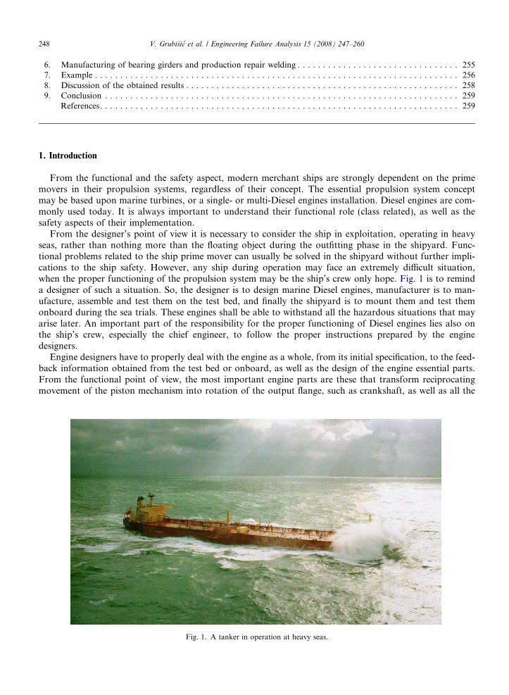
From the designer’s point of view it is necessary to consider the ship in exploitation, operating in heavyseas, rather than nothing more than the floating object during the outfitting phase in the shipyard. Func-tional problems related to the ship prime mover can usually be solved in the shipyard without further impli-cations to the ship safety. However, any ship during operation may face an extremely difficult situation,when the proper functioning of the propulsion system may be the ship’s crew only hope. Fig. 1 is to reminda designer of such a situation. So, the designer is to design marine Diesel engines, manufacturer is to man-ufacture, assemble and test them on the test bed, and finally the shipyard is to mount them and test themonboard during the sea trials. These engines shall be able to withstand all the hazardous situations that mayarise later. An important part of the responsibility for the proper functioning of Diesel engines lies also onthe ship’s crew, especially the chief engineer, to follow the proper instructions prepared by the enginedesigners.
Engine designers have to properly deal with the engine as a whole, from its initial specification, to the feed-back information obtained from the test bed or onboard, as well as the design of the engine essential parts.From the functional point of view, the most important engine parts are these that transform reciprocatingmovement of the piston mechanism into rotation of the output flange, such as crankshaft, as well as all the
Fig. 1. A tanker in operation at heavy seas.

V. Grubisic et al. / Engineering Failure Analysis 15 (2008) 247–260 249
parts taking part in transmission of generated forces to the engine foundation, e.g. the bed plate, the framebox, or the cylinder block. In modern large Diesel engines (Fig. 2) bedplates usually consist of their outer partmade of steel plates, connected together by means of cast steel bearing girders. These bearing girders take overand distribute forces acting on the engine bedplate as a whole, originating from assembly pre-loading by tierods, cylinder firing loads and bearing reactive loads. A typical bedplate of a modern large Diesel engine maybe seen in Fig. 3 during the assembly process.
This paper is initiated as a consequence of cracks that developed in several Diesel engine bearing girdersin newly built ships and the investigation of the problem cause. The basic aim of the paper is to describethe present state-of-the-art methodology, which has to be implemented in design and manufacturing ofmodern Diesel engine bearing girders. The design of these components shall be based upon a proper struc-tural durability evaluation. The manufacture shall be based upon the proper implementation of qualityassurance procedures (production and testing specifications) in general. The final goal of all the mentionedprocedures is to avoid any undesirable effects and to prevent initial crack development in similarstructures.
The design procedures based upon loading assumptions, selection of suitable materials and the manufac-turing procedures, as well as the shaping and dimensioning procedures are described in details. The transitionfrom cylinder loading and tie-rods pre-load to the existing stresses in critical parts of bearing girders isexplained. On the other hand, evaluation of structural material properties for cast steel bearing girders inaccordance with the international standards, such as ASTM, or FKM-Guideline, dependent also upon the ini-tial and the in-service scope of inspections implemented. It is important to validate design premises andassumptions, as well as calculated results by measurements, even for only few measurement points and influ-ence factor levels.
Fig. 2. A large two-stroke marine Diesel engine at test bed.
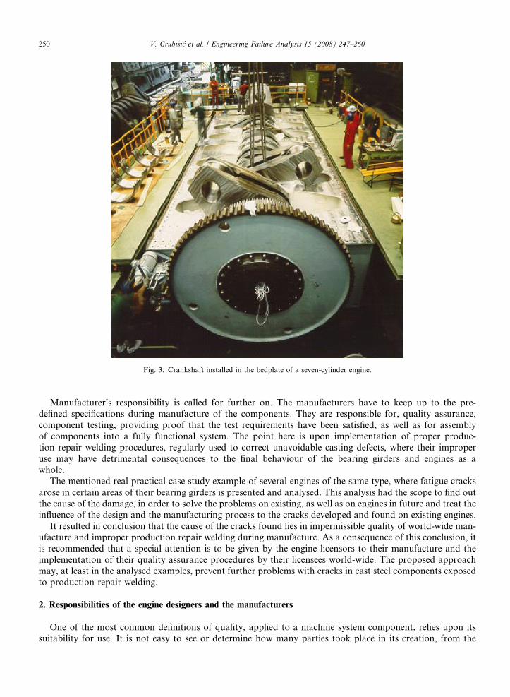
Fig. 3. Crankshaft installed in the bedplate of a seven-cylinder engine.
250 V. Grubisic et al. / Engineering Failure Analysis 15 (2008) 247–260
Manufacturer’s responsibility is called for further on. The manufacturers have to keep up to the pre-defined specifications during manufacture of the components. They are responsible for, quality assurance,component testing, providing proof that the test requirements have been satisfied, as well as for assemblyof components into a fully functional system. The point here is upon implementation of proper produc-tion repair welding procedures, regularly used to correct unavoidable casting defects, where their improperuse may have detrimental consequences to the final behaviour of the bearing girders and engines as awhole.
The mentioned real practical case study example of several engines of the same type, where fatigue cracksarose in certain areas of their bearing girders is presented and analysed. This analysis had the scope to find outthe cause of the damage, in order to solve the problems on existing, as well as on engines in future and treat theinfluence of the design and the manufacturing process to the cracks developed and found on existing engines.
It resulted in conclusion that the cause of the cracks found lies in impermissible quality of world-wide man-ufacture and improper production repair welding during manufacture. As a consequence of this conclusion, itis recommended that a special attention is to be given by the engine licensors to their manufacture and theimplementation of their quality assurance procedures by their licensees world-wide. The proposed approachmay, at least in the analysed examples, prevent further problems with cracks in cast steel components exposedto production repair welding.
2. Responsibilities of the engine designers and the manufacturers
One of the most common definitions of quality, applied to a machine system component, relies upon itssuitability for use. It is not easy to see or determine how many parties took place in its creation, from the
V. Grubisic et al. / Engineering Failure Analysis 15 (2008) 247–260 251
design to the final testing prior to delivery. In modern industrial society the parties that may be recognised at afirst glance are the designer, the manufacturer and the system supplier [1].
Design of the component always defines the direction of all further steps to be made in its manufacture andbehaviour in exploitation. The designer is responsible for the following [1]:
� full description of the requirements which the components are to satisfy with specified conditions for theiruse;� evaluation or estimation of operating loads and component strength;� constructional shaping and dimensioning;� selection of suitable materials appropriate to the loading; and� selection of the manufacturing methods.
On the other hand, the responsibilities of the manufactures are basically related to the fabrication of thecomponent itself. These consist of the following [1]:
� manufacture of the components in accordance with clear and complete specifications for the design and inaccordance with standard engineering practice;� assurance of component quality in accordance with the use-related specifications;� examination of the components in accordance with prescribed and agreed testing methods;� proof that the test requirements have been satisfied; and� assembly with other parts to form a unit.
System suppliers are responsible for [1]:
� assembly of all the necessary units and equipment to form plants capable of operation;� adjusting of plant adjustable parameters if necessary;� final testing of assembled and built-in plants in accordance with the test specifications;� proof that all the prescribed and agreed tests have been performed with the results that satisfy the require-
ments, prior to the delivery of the whole plant.
In modern shipping business all this applies to the bearing girders as the components, marine Diesel engineas the unit and, finally, to the whole ship as a unit. Designers of the two-stroke slow speed large marine Dieselengines, together with all the engine components such as bearing girders, are usually licensors themselves(presently, there remain only three significant international companies in large two-stroke marine Dieselengines business). Manufacturers are their world-wide licensees, i.e., Diesel engine factories around the world.System suppliers are, in this context, the shipyards.
One of the important aspects of a component/unit/plant operational behaviour in practical exploitationfurther on lies upon the ship operators. These are the shipping companies (ship owners or management com-panies). Their responsibilities are to always keep up to the operating instructions prescribed by the designersand to avoid any misuse or abuse.
In investigations of any failure, if it happens, independent experts are usually engaged to determine its rootcause. Upon the above-defined responsibilities once uncovered cause usually leads to an answer who is respon-sible for the failure. This is one of the basic reasons for writing of this paper: to write down a procedure, basedupon objective evidence and own experience, to be used by these experts in future, so as to exclude the influ-ence of any party interest.
3. Design procedures for general machinery components
In general, design of a component involves the following activities: load assumption, selection of suitablematerials and manufacturing procedures, shaping and dimensioning [1]. The design is dependent on the actingloads and the stresses caused by these loads in individual areas of the component, as well as the allowablestresses, influenced by the material and the manufacture. Dimensioning of components is always dependent

252 V. Grubisic et al. / Engineering Failure Analysis 15 (2008) 247–260
on the relation between the stresses that arise and the stresses that can be tolerated. Designer’s task is to deter-mine the stresses that arise through the calculation and, starting from the material characteristics and theexpected manufacturing quality, to determine the allowable stresses.
Designers shall take into account all the stresses that are brought about by various causes, in order to deter-mine the strength behaviour of the designed components. These are the stresses produced by assembly andoperation:
� static or quasi-static pre-stresses during assembly and or warming up of the unit;� static pre-stresses, called residual stresses, that can arise during component manufacture;� dynamic time-dependent stresses superimposed to the pre-stresses in operation.
In addition to these it is important that the designer determines all additional influences relevant to thecomponent strength behaviour with respect to the permissible stresses, such as material inhomogenities, sur-face roughness, etc.
4. A state-of-the art design procedure for the bearing girders
The above-described general methodology is valid for two-stroke slow-speed marine Diesel engine bearinggirders and is to be applied to their design. Each step, together with all the influencing parameters will bedescribed in detail hereafter. The essential steps are determination of the bearing loads, calculation of thestresses, and, finally the assessment of the bearing girder fatigue strength [2].
4.1. Determination of the bearing loads
Bearing forces are to be determined as a first stage in the computational analysis of the stresses in bear-ing girders. Mapping of the bearing housing deformation during installation and operation load, that pointboth to a displacement and also to redistribution of the forces in the bearing girders is of a particular inter-est. This is also significant for the load distribution in the bearing girder, since the force flow from the bear-ing is not only lead away via the wall of the bearing girder. Asymmetrical distribution of the load broughtabout by deformation of the crankshaft along the bearing shell shall also be taken into account in thecalculation.
So, the decisive loads to be taken into account are defined in Table 1.
Table 1Determination of bearing girders loading
Internal engine forces Ignition forces Caused by firing process in engine cylinderObtained from the cylinder pressure versuscrank angle curve
Guide shoe forces Obtained from ignition and reciprocatingmechanism inertial forces
Forces acting on main bearings Consequence of forces acting on crank journalsElastic system response to the active forces(bearing reactions)Require crankshaft modellingRequire taking at least three cylinders intoaccount
Loads originating fromassembly forces
Pre-tensioning of tie-rodsPre-tensioning of bearing cover boltsAssembly stresses to be added to other calculatedstresses
Dynamic loads Crankshaft vibration forces (coupled vibrations)Hydrodynamic loading by the oil-film in the bearings(dynamic alignment)
V. Grubisic et al. / Engineering Failure Analysis 15 (2008) 247–260 253
4.2. Calculation of the stresses
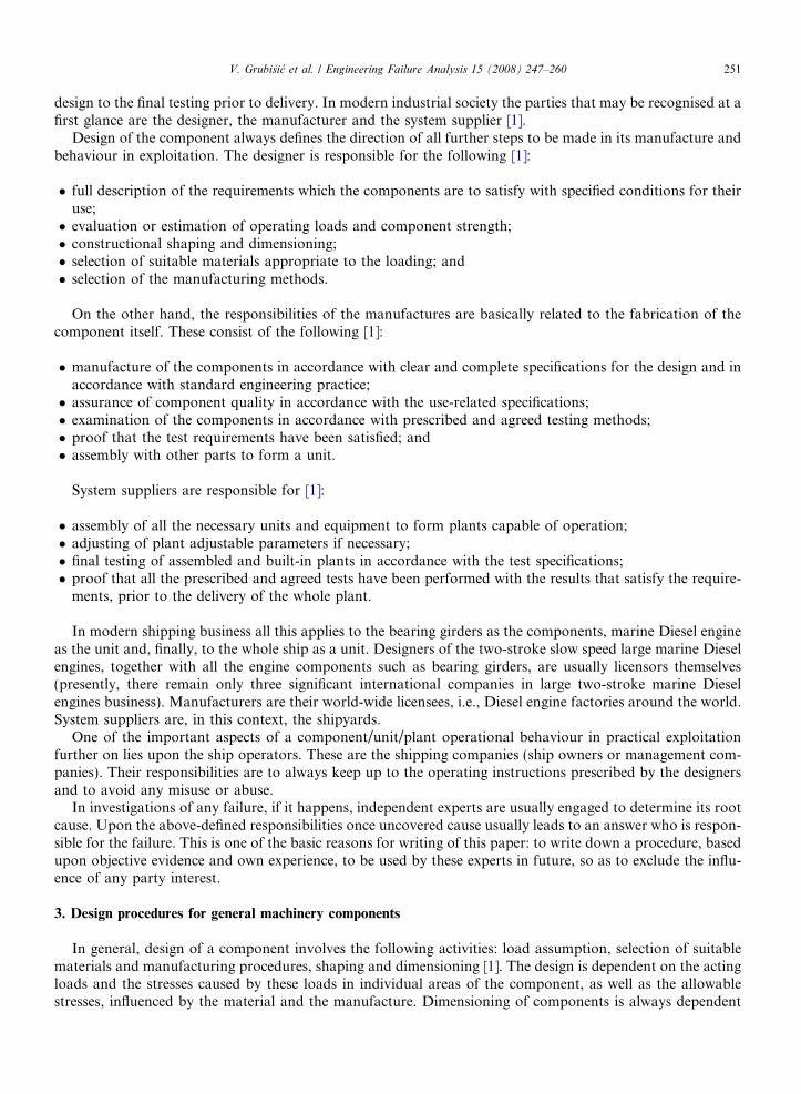
The engine structural modelling, utilising the finite element method for the deformation analysis is tostart from the whole engine to the section with the three cylinders. In fact, the two complete cylinders,and the two halves of the neighbouring ones disposed around the bearing girder are to be evaluated [3].The last step is to evaluate the bearing girder itself. Selection of the finite elements and numerical calcula-tion procedure is to be in accordance with the state-of-the-art, meaning 3D finite elements and a non-linearcalculation procedure. A typical part of the engine single bearing girder to be numerically modelled isshown in Fig. 4 [3].
The structural finite element model of the bearing girder shown in Fig. 5 [3] lies between the two ‘‘whole’’cylinders within the model. The influence of bearing forces out of the modelling scope (two complete cylindersand two halves) on the forces acting on the considered bearing girder may be neglected [3].
The whole calculation procedure is implemented to determine stresses in the considered (model mid-sec-tion) bearing girder. Iterative calculations are necessary. Namely, the crank journals at a certain rpm do notlie directly on the bearing, but on a lubricating oil-film between the journal and the bearing. Crankshaft isto be modelled as a whole, together with the remaining parts of the propulsion system (intermediate shaft,propeller shaft and the propeller). Elasto-hydrodynamic properties of oil-film are to be taken into account[2].
Finite element mesh refinement in the model is necessary in order to prove the convergence of numericalcalculations, as well as because the tilt of crankshaft journals in both radial and tangential direction has a sig-nificant influence. This gives a very extensive and complex numerical model used to determine acting stressesin bearing girders.
cylinder jacket (grey cast iron)
frame box (welded)
bedplate (welded)
girder (cast steel)
Fig. 4. A typical cross-section at engine bearing girder with parts.

Fig. 5. Finite element model of the engine bearing girder.
50
R300A
C
B
(wall thickness)
Fig. 6. Zones of strength validation based on FEM model.
254 V. Grubisic et al. / Engineering Failure Analysis 15 (2008) 247–260
4.3. Assessment of the bearing girders fatigue strength
Consequently, the multi-axial stresses in the highly loaded points of the bearing girder analysed are pre-sumed to be the critical ones. These are composed of static pre-stresses (preferably arising during installation

V. Grubisic et al. / Engineering Failure Analysis 15 (2008) 247–260 255
as a consequence of tightening torque in the tie-rods and bearing cover bolts) and the variable (dynamic) stres-ses, which are superimposed on these during operation. During a single rotation of the crankshaft these stres-ses change both their value and the direction. Zones of strength validation, based on finite element analysis,for a particular case (see Example) are shown in Fig. 6 [3].
Based upon the calculated stresses, the equivalent stresses are to be determined in accordance with thematerial dependent fracture hypothesis. These equivalent stresses are then compared with the allowablestresses determined from samples with uni-axial stresses. In the case of cast steel bearing girders the nor-mal stress hypothesis is to be implemented. Determined allowable stresses shall also take into accountmaterial type, as well as the initial and periodical regime of inspections implemented (annual and/or classsurveys) [4]. International standards and guidelines such as FKM-Guideline [5] and ASTM [6] are to beimplemented.
The way to compare these stresses in a particular analysed case is shown in the forthcoming Example.
5. Validation of bearing girders design by experiments
It is important to prove and evaluate how accurately do the computationally determined stresses in indi-vidual areas of the bearing girders correspond with the stresses arising in operation. This can only be suppliedby the corresponding operational measurement.
The experiments are to shed enough light to the parameters taken into account in the numerical calcu-lations, especially if all these parameters have had been necessary to deal with or not. Experimental valida-tion of the numerical model at only few (to reduce costs) levels of parameters is necessary. A similarapproach is quite common in marine engineering and is, in certain cases, even the requirement of classifi-cation societies [4]. Fig. 7 [3], referred to in the Example, shows comparison of calculated stresses to themeasured ones.
6. Manufacturing of bearing girders and production repair welding
The bearing girders are predominantly manufactured from cast steel. For cast components of the size ofbearing girders it is assumed, on the one hand, that an appropriate casting quality is guaranteed, and on theother hand that if casting quality is inadequate, a repair can be effected. Usually, the so-called productionrepair welding improves the components with casting failures. The requirements for the quality of bearinggirders, as well as the procedure for repair welding, must be described in the quality assurance specifications.
-70
-60
-50
-40
-30
-20
-10
0
10
20
0˚ 30˚ 60˚ 90˚ 120˚ 150˚ 180˚ 210˚ 240˚ 270˚ 300˚ 330˚ 360˚
(N
/mm
2 )
Ship 1 Ship 2 FEM
Fig. 7. Comparison of FEM calculations with measurements.

Zone l
Zone ll
Zone ll
Zone l
Bearing SaddleZone
1/3
20m
m
1/3 1/3
Zone lI
A
A
A-A
Fig. 8. Zones of specified material defects.
256 V. Grubisic et al. / Engineering Failure Analysis 15 (2008) 247–260
With the production repair welding the faults caused in production should be removed and the requirednature of the casting [5,6] should be ensured, which should have the characteristics similar to the basicmaterial.
To assure a reliable and economical repair the bearing girder is, depending on the stress distribution (resultsof FE-stress analysis), divided into individual zones (shown for example in Fig. 8) on which the specified cast-ing failures can be accepted or, depending on their shape and position, repaired. These requirements should bespecified at the design stage in a close cooperation with the engineers being responsible for the manufacturing.If the casting faults are higher than allowable, but possible to improve by repair welding, this could be made ifthe specified conditions are fulfilled. Depending on the size of the component to be repaired it is necessary todecrease the residual stresses generated by the repair welding. In such a case the American Society for Testingand Materials [6] requires that a residual stress treatment by annealing must take place if the extent in depthamounts to more than 20% of the wall thickness, or more than 1 in. (25.4 mm), with the respectively lowervalue being decisive.
7. Example
Implementation of the described procedure for the structural strength calculation and validation ofobtained results is presented below in a real case study example. These analyses refer to several engines ofthe same type, where fatigue cracks arose in certain areas of their bearing girders. The basic goal of these cal-culations was to investigate and find out the cause of the damage [1,2].
The first step in the analyses performed was modelling of the engine structure. This was done by means offinite element methods analysis for linear elastic behaviour of material of engine components and a very com-plex non-linear behaviour of oil-film in the bearings in operation. The analysis was performed in three steps:from the whole engine, through the section with three cylinders disposed around the bearing girder to be eval-uated, to the bearing girder itself.
Once stresses in isolated bearing girder have been obtained, the calculated local stresses become the basisfor further evaluation of bearing girder strength. As has already been point out, the multi-axial stresses, pres-ent in highly loaded points of the bearing girder are presumed to be critical. So, it is essential to properly rec-ognise position of these points and to analyse stresses in them. Zones of interest, where these points may lie areshown in Fig. 8.
In determination of these points it is important to understand the basic function of the bearing girders.They are incorporated into the complete engine structure in such a way that the bearing forces are transmittedinto the foundation both through the bearing girder itself and also through the lateral plates. Consequently,

V. Grubisic et al. / Engineering Failure Analysis 15 (2008) 247–260 257
loading at individual positions of the bearing girder is not determined only by the bearing girder wall thick-ness. On the other hand, within a cracked bearing girder a redirection of the force takes place, leading to adelay of the crack propagation.
Three characteristic points have been chosen for further detailed fatigue strength analyses, as shown inFig. 6:
� Point A, located centrally below the lower bearing half (radius 30 mm).� Point B, located in the area of central web (thickness 50 mm).� Point C, transition to the tie-rod bore (radius 80 mm).
Variation of thickness has also been taken into account. This is important because of the manufacturingtolerances for cast steel bearing girders.
The specially evaluated areas, with the characteristic points A, B and C denoted have been shown in Fig. 9[1]. Pre-stresses exist in points A, B and C as a consequence of assembly. They amount to +30/�40 MPa (ten-sile/compressive stress) in the presumed critical points B and C, and to only +4/�3 MPa (main compressivestress) in point A. The oscillating operating stresses are superimposed to these pre-stresses.
The wall thickness variation of 50–45 mm (where the nominal value is 50 mm) has a notable influence onlyin the area of the point B (increase of approximately 10%). However, reduction of the web thickness in thearea of points A and C does not have any notable influence to the stresses.
Finally, the resultant stress (pre-stress with the superimposed dynamic alternating stress) achieves the fol-lowing values:
Point A: �40 ± 45 MPaPoint B: �36 ± 37 MPaPoint C: �26 ± 50 MPa
Assessment of strength is based upon comparison of the acting stresses with the allowable stresses. The lat-ter were determined on the basis of the available data for the fatigue strength of cast steel GS 38.
The following influences effecting fatigue strength have been considered:
Fig. 9. Fatigue assessment in characteristic points.
258 V. Grubisic et al. / Engineering Failure Analysis 15 (2008) 247–260
� Engine operation of 6000–7000 h per year, with the total service life of 20 yr at nominal engine speed of70 rpm gives a total of 580 million load reversals. Although the loading for the load reversals does notalways correspond to 100% a fatigue strength at which no fatigue damage would have arisen for the allow-able component stress has been selected.� This allowable component stress is derived from fatigue strength tests with corresponding material samples,
with the aid of safety factors. The starting basis is the fatigue strength found for 2–10 million load reversals,called the endurance limit. Natural scattering of the material characteristics calls for introduction of safetyfactors for determination of the allowable stresses.� ASME code [6] determines allowable stresses by dividing average fatigue strength (at 50% probability of
survival) with the safety factor of 2.� FKM-Guideline [5] determines allowable stresses by dividing fatigue strength (at 97.5% probability of sur-
vival) with the safety factor of 1.3–1.5.� Both standards lead finally to almost the same value of allowable stress, so the use of only FKM-Guideline
in further considerations is thus found acceptable.
The allowable stress rall is determined by taking into account the material properties rM, the expected fati-gue strength of the components (factor K1< 1), the fatigue decrease factor for 109 cycles (factor K2 < 1 relatedto fatigue strength, usually determined for 2 · 106 cycles, known as the endurance limit), as well as the safetyfactor So specified for given usage conditions:
rall ¼ rM; 97:5% � K1 � K2=So ð1Þ
where:So safety factor, So = 1.3 in accordance with FKM;rM, 97.5% material fatigue strength for 97.5% probability of survival;K1 = 0.7 factor related to the components fatigue strength for cast girder material GS 38 with thickness of
50–70 mm and quality assurance implemented for areas with high stresses;K2 = 0.9 factor taking into account the decrease of the fatigue strength for 20 yr of usage, equivalent to � 109
cycles in relation to the fatigue strength at 2 · 106 cycles for cast girders.
Allowable stress for the cast steel girders may be calculated as presented in the formula (2), whererM, 97.5% � ± 110 MPa (R = �1) based on the data in the relevant standards (for the castings of GS 38 withRm = 380 MPa):
rall ¼ rM; 97:5% � 0:7 � 0:9=1:3 ¼ 0:49 � rM; 97:5% ¼ 0:49 � 110 ¼ �53 MPa ðR ¼ �1Þ ð2Þ
Fig. 9 [1] shows the corresponding Haigh diagram for the fatigue assessment, i.e., the assessment of the fatiguestrength in characteristic bearing girder points based upon Haigh diagram from FKM-Guideline [5]. The fi-nally obtained safety values lie between 2.4 and 3.4. This is higher than the maximum safety factor of 1.8 re-quired by the FKM-Guideline, taking into account cast components have not been initially tested, thatcontain permissible errors, where no regular inspections are foreseen and the consequences of possible damageare severe.
8. Discussion of the obtained results
The obtained results prove that the bearing girders of the engine in question, with a nominal web thicknessof 50 mm have been designed properly and in accordance with the state-of-the-art. Consequently, the reasonfor cracks, which have been detected in bearing girders, is to be looked for elsewhere, but not in the design ofbearing girders [1,2].
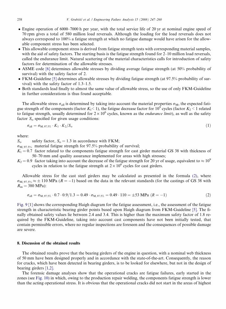
The forensic damage analyses show that the operational cracks are fatigue failures, early started in thezones (see Fig. 10) in which, owing to the production repair welding, the components fatigue strength is lowerthan the acting operational stress. It is obvious that the operational cracks did not start in the areas of highest
Type 2
Type 1
Fig. 10. Operational cracks in bearing girders.
V. Grubisic et al. / Engineering Failure Analysis 15 (2008) 247–260 259
stresses but in the areas in which the components fatigue strength was decreased by the poor production repairwelding.
The operational stress level in the bearing girder is low and this was confirmed by a very slow crack prop-agation. After a crack has arisen, a continuous redistribution of the effective load takes place with its propa-gation, which can lead to a delay of the crack propagation up to a temporarily crack stopping. Regardless ofthis, a repair of the bearing girder is required because of the possible serious damages to the main bearing shellwith a potential impact to the crankshaft in case of uncontrolled crack propagation.
9. Conclusion
The procedure of structural durability validation of bearing girders in large two-stroke marine Dieselengines, as shown in this paper, is a basis for a reliable lightweight design of modern engines. It is also nec-essary to prove the cause and the responsibility in the case that the damages (failures) occur at operationalusage.
The presented and analysed example proves the necessity of the presented procedure also to determine thequality assurance specifications and the requirements for the production repair welding.
Production repair welding in cast components is a normal practice. This kind of repair of casting defectscan not be avoided for economical and practical reasons. Production repair welding is to be performed inaccordance with the prescribed quality procedures, based on standards and correctly supervised accordinglyby independent bodies.
References
[1] Grubisic V. Evaluation of the method for the design of the bearing girders of RTA84T/RTA84T-B two-stroke diesel engines includingthe quality controls provided. Report for Wartsila Switzerland AG, Reinheim; 2003.
[2] Vulic N. Validation of the procedure used by Wartsila Switzerland to determine the stresses of two-stroke diesel engine bearing girders.Report for Wartsila Switzerland AG, Split; 2003.
[3] Sonnichsen S. Design and evaluation of cast steel girder 7RT84T-B. Wartsila Switzerland Internal Report, Winterthur; 2003.[4] Rules for the technical supervision of sea-going ships, part 9 – Machines. Croatian Register of Shipping, Split; 2004.

260 V. Grubisic et al. / Engineering Failure Analysis 15 (2008) 247–260
[5] FKM guideline. Analytical strength assessment of components in mechanical engineering, 5th Ed. ForschungskuratoriumMaschinenbau (FKM), Frankfurt/Main; 2003.
[6] ASTM A148 – Standard specifications for high strength steel castings for structural purposes. American Society for Testing andMaterials, West Conshohocken; 1979.