structural designers guide
TRANSCRIPT
STRUCTURALDESIGNERS GUIDE
+RIBRAFT® X-POD®
OCTOBER 2021
1 Scope 3
2 Description of the System 3
1 DPM 4
2.1 Concrete 4
2.2 Pods 4
2.3 Mesh 6
2.4 Steel 6
2.5 DPM 7
2.6 Optional Gravel raft 7
2.7 Firth HotEdge® 7
2.8 Drawings 8
3 Typical Uses 8
4 Design of the system 8
4.1 Design case 1 - Design to AS/NZS1170 for ground bearing 8
4.2 Design Case 2 - Design for Liquefaction sites 10
4.3 Design case 3 - Design for expansive soil site 11
5 R values 12
6 Plumbing 13
6.1 Below Slab Plumbing Installation Methodology 13
6.2 In Floor Plumbing Installation methodology 14
6.3 Recesses for showers 16
7 Finish floor level above ground 17
8 Design Documentation 17
9 References 17
1 SCOPE
This design guide has been developed for the exclusive use
of CPEng designers who are experienced in the design of
residential concrete foundation systems. Only Chartered
Professional Engineers with appropriate experience, or
persons working under their supervision, shall rely on the
information provided in this document.
The system requires specific design and this document
provides guidance for suitably qualified persons to design
RibRaft® X-Pod® foundation systems for sites which are
either:
• Not prone to liquefaction
• Potential for liquefaction and categorised as TC2 using
the MBIE guideline(3)
• Sites containing expansive soils
Use of the Manual entails a commitment by the Designer
to specify that the concrete shall be supplied by Firth
Industries. The X-Pod®s are only available from Firth
Industries and shall only be supplied to a project with
confirmation of an order for Firth concrete.
2 DESCRIPTION OF THE SYSTEM
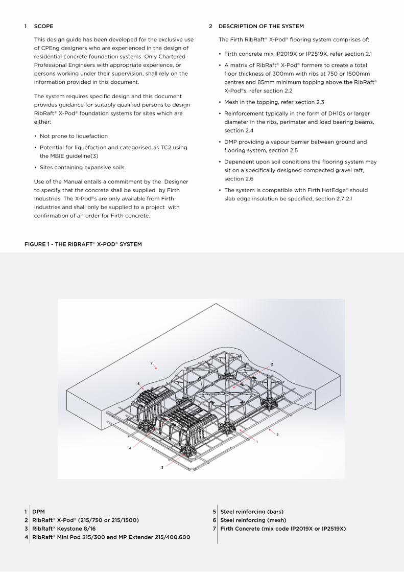
The Firth RibRaft® X-Pod® flooring system comprises of:
• Firth concrete mix IP2019X or IP2519X, refer section 2.1
• A matrix of RibRaft® X-Pod® formers to create a total
floor thickness of 300mm with ribs at 750 or 1500mm
centres and 85mm minimum topping above the RibRaft®
X-Pod®s, refer section 2.2
• Mesh in the topping, refer section 2.3
• Reinforcement typically in the form of DH10s or larger
diameter in the ribs, perimeter and load bearing beams,
section 2.4
• DMP providing a vapour barrier between ground and
flooring system, section 2.5
• Dependent upon soil conditions the flooring system may
sit on a specifically designed compacted gravel raft,
section 2.6
• The system is compatible with Firth HotEdge® should
slab edge insulation be specified, section 2.7 2.1
FIGURE 1 - THE RIBRAFT® X-POD® SYSTEM
1 DPM
2 RibRaft® X-Pod® (215/750 or 215/1500)
3 RibRaft® Keystone 8/16
4 RibRaft® Mini Pod 215/300 and MP Extender 215/400.600
5 Steel reinforcing (bars)
6 Steel reinforcing (mesh)
7 Firth Concrete (mix code IP2019X or IP2519X)
7
6
4
5
1
2
3
2.1 CONCRETE
RibRaft® X-Pod® Foundation systems require a specific Firth
designed concrete mix. Choose one of the following:
1 X-Pod® Mix IP2019X – a 20MPa 120mm slump mix
available as a pump mix suitable for 100mm pump lines
available in either a 13mm or more usually a 19mm nominal
aggregate size, or as a structural (non-pump) mix
2 X-Pod® Mix IP2519X – a 25MPa 120mm slump mix
available as a pump mix suitable for 100mm pump lines
available in either a 13mm or more usually a 19mm nominal
aggregate size, or as a structural (non-pump) mix. This
mix shall be specified for buildings constructed in the
‘sea spray zone’ (i.e. within 500m of the sea including
harbours, within 100m of tidal estuaries or inlets, on
offshore islands and elsewhere as defined as exposure
zone D in 4.2.3.3 of NZS3604).
The X-Pod® system is available across most of NZ,
where there is a Firth Concrete plant available to supply
the X-Pod® special mix concrete. However in some
parts of the county, X-Pod® isn’t available including
Kaitaia, Wairarapa, Kaikoura, Motueka and Golden Bay,
where there is no Firth Plant or a Firth Plant is too far
away to make the supply of X-Pod® concrete feasible.
In these cases, please talk to your local Firth rep for
more information and to discuss a suitable alternative
foundation design.
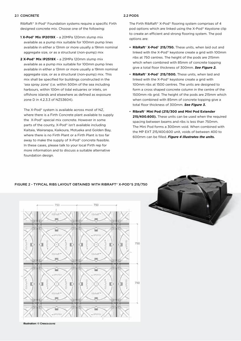
2.2 PODS
The Firth RibRaft® X-Pod® flooring system comprises of 4
pod options which are linked using the X-Pod® Keystone clip
to create an efficient and strong flooring system. The pod
options are:
• RibRaft® X-Pod® 215/750. These units, when laid out and
linked with the X-Pod® keystone create a grid with 100mm
ribs at 750 centres. The height of the pods are 215mm
which when combined with 85mm of concrete topping
give a total floor thickness of 300mm. See Figure 2.
• RibRaft® X-Pod® 215/1500. These units, when laid and
linked with the X-Pod® keystone create a grid with
100mm ribs at 1500 centres. The units are designed to
form a cross shaped concrete column in the centre of the
1500mm rib grid. The height of the pods are 215mm which
when combined with 85mm of concrete topping give a
total floor thickness of 300mm. See Figure 3.
• Ribraft® Mini Pod (215/300 and Mini Pod Extender
215/400.600). These units can be used when the required
spacing between beams and ribs is less than 750mm.
The Mini Pod forms a 300mm void. When combined with
the MP EXT 215/400.600 unit, voids of between 400 to
600mm can be filled. Figure 4 illustrates the units.
FIGURE 2 - TYPICAL RIBS LAYOUT OBTAINED WITH RIBRAFT® X-POD®S 215/750
2.1 CONCRETE
RibRaft® X-Pod® Foundation systems require a specific Firth
designed concrete mix. Choose one of the following:
1 X-Pod® Mix IP2019X – a 20MPa 120mm slump mix
available as a pump mix suitable for 100mm pump lines
available in either a 13mm or more usually a 19mm nominal
aggregate size, or as a structural (non-pump) mix
2 X-Pod® Mix IP2519X – a 25MPa 120mm slump mix
available as a pump mix suitable for 100mm pump lines
available in either a 13mm or more usually a 19mm nominal
aggregate size, or as a structural (non-pump) mix. This
mix shall be specified for buildings constructed in the
‘sea spray zone’ (i.e. within 500m of the sea including
harbours, within 100m of tidal estuaries or inlets, on
offshore islands and elsewhere as defined as exposure
zone D in 4.2.3.3 of NZS3604).
The X-Pod® system is available across most of NZ,
where there is a Firth Concrete plant available to supply
the X-Pod® special mix concrete. However in some
parts of the county, X-Pod® isn’t available including
Kaitaia, Wairarapa, Kaikoura, Motueka and Golden Bay,
where there is no Firth Plant or a Firth Plant is too far
away to make the supply of X-Pod® concrete feasible.
In these cases, please talk to your local Firth rep for
more information and to discuss a suitable alternative
foundation design.
2.2 PODS
The Firth RibRaft® X-Pod® flooring system comprises of 4
pod options which are linked using the X-Pod® Keystone clip
to create an efficient and strong flooring system. The pod
options are:
• RibRaft® X-Pod® 215/750. These units, when laid out and
linked with the X-Pod® keystone create a grid with 100mm
ribs at 750 centres. The height of the pods are 215mm
which when combined with 85mm of concrete topping
give a total floor thickness of 300mm. See Figure 2.
• RibRaft® X-Pod® 215/1500. These units, when laid and
linked with the X-Pod® keystone create a grid with
100mm ribs at 1500 centres. The units are designed to
form a cross shaped concrete column in the centre of the
1500mm rib grid. The height of the pods are 215mm which
when combined with 85mm of concrete topping give a
total floor thickness of 300mm. See Figure 3.
• RibRaft® two part adjustment pod. ADJ Pod
(215/150.400 and ADJ Pod 215/450.700). These units can
be used when the required spacing between beams and
ribs is less than 750mm. The 215/150.400 unit contains a
top mounted clip which allows it to be securely connected
to other X-Pod® units. Without modification the unit fills
a 400mm void. With cutting and overlapping the unit can
fill voids of between 150 and 400mm. When combined
with the ADJ 215/450.700 unit, voids of between 450 to
700mm can be filled. Figure 4 illustrates the units.
FIGURE 2 - TYPICAL RIBS LAYOUT OBTAINED WITH RIBRAFT® X-POD®S 215/750
Illustration: © Cresco.co.nz
750 750
750
750
FIRTH RIBRAFT® X-POD® STRUCTURAL DESIGNERS GUIDE4
Illustration: © Cresco.co.nz

Firth RibRaft® X-Pod®s are placed directly on levelled ground and are arranged in such a way as to form a reinforced
concrete floor slab with a grid of reinforced concrete ribs and edge beams when concrete is placed onto them. The
RibRaft® Mini Pods Series X-Pod®s may be used to suit specific architecture layout and also to accommodate services.
Figure 5 shows how the various X-Pod® components might be utilised on a complex floor arrangement where liquefaction
or expansive soils are not a consideration.
FIGURE 3 - TYPICAL RIBS LAYOUT OBTAINED WITH RIBRAFT® X-POD®S 215/1500
FIGURE 4 RIBRAFT XPOD MINI POD AND MP EXTENDER
Illustration: © Cresco.co.nz
FIGURE 4 - RIBRAFT® X-POD® TWO PART ADJUSTMENT PODS
Illustrations: © Cresco.co.nzRibRaft® X-Pod® ADJ 215/150.400 RibRaft® X-Pod® ADJ 215/450.700
Firth RibRaft® X-Pod®s are placed directly on levelled ground and are arranged in such a way as to form a reinforced
concrete floor slab with a grid of reinforced concrete ribs and edge beams when concrete is placed onto them. The
RibRaft® ADJ Series X-Pod®s may be used to suit specific architecture layout and also to accommodate services.
Figure 5 shows how the various X-Pod® components might be utilised on a complex floor arrangement where liquefaction
or expansive soils are not a consideration.
FIGURE 3 - TYPICAL RIBS LAYOUT OBTAINED WITH RIBRAFT® X-POD®S 215/1500
1500
1500
Illustration: © Cresco.co.nz
FIRTH RIBRAFT® X-POD® STRUCTURAL DESIGNERS GUIDE5
RibRaft® Xpod Mini Pod 215/300 RibRaft® Xpod Mini Pod 215/300 and MP Extender 215/400.600

RIBRAFT™X-POD 215/750
BEAR
ING
WAL
LTO
BE
SUPP
OR
TED
WIT
HIN
TH
IS A
REA
N.4 RIBRAFT™X-PODS 215/1500
ALTERNATIVEARRANGEMENT OF PODS
RIBRAFT™MINIPOD
FIGURE 5 - EXAMPLE OF HOW THE VARIOUS X-POD® COMPONENTS CAN BE UTILISED ON A COMPLEX SHAPED FLOOR
2.3 MESH
Mesh shall be Grade 500 and comply with AS/NZS
4671:2001. Typically the mesh will be 665 mesh (Class L)
or SE62 ductile mesh (Class E). The design engineer shall
specify the required mesh.
Class L mesh can be used when the sole purpose is
limitation of crack widths and the ground conditions
are defined as good in terms of NZS3604. The Class E
reinforcing bars in the ribs and beams provides adequate
ductility of the system which allow the use of Class L mesh.
Class E shall be used when the mesh preforms a structural
function such as a slab on ground prone to liquefaction or
expansive soils.
Mesh shall be lapped in accordance with NZS3101.
Two options are available for supporting the mesh:
1 The mesh can be supported on mesh chairs to achieve
cover to the top surface of 35mm. This methodology
minimises the cover and therefore enhances the crack
width limiting ability of the mesh. It also maximises the
internal leverarm and therefore the bending strength
when subjected to moments causing the mesh to go
into tension.
2 The mesh can alternatively be laid on upstands provided
in the corners of the pods. The 15mm upstands on the
pods mean that cover from the concrete surface to the
mesh (SE62) is 58mm and slightly less at mesh overlaps.
This solution provides greater economy and stability of
the mesh.
2.4 STEEL
The reinforcing bars in the ribs and edge beams shall
conform to AS/NZS 4671:2001 Grade 500, Class E “Steel
Reinforcing Materials”. The volume of reinforcement shall be
determined by the designer.
For sites not prone to liquefaction or expansion, the ribs
(100mm wide) are normally reinforced with a single DH10
and the perimeter edge beam (minimum 250mm wide)
with 2DH10s at the bottom and one DH10 in the plane
of the mesh. This volume of reinforcement satisfies the
minimum flexural reinforcement requirements for NZS3101.
The Keystones hold the reinforcement in positon without
the need for tying. The Keystone can accommodate up to
two DH16 bars at a lap positon.

2.5 DPM
The damp proof membrane (DPM) material shall be polyethylene sheet in accordance with NZS 3604:2011. The DPM shall be laid
over the entire building platform directly on top of a sand blinding layer, extending to the outside of the edge beam. The joints
shall be lapped not less than 50mm and sealed with pressure sensitive tape not less than 50mm wide. All penetrations of the
DPM by plumbing and services or punctures during construction shall also be sealed with pressure sensitive tape. The DPM may
extend beyond the edge of the slab i.e. underneath the formwork, or may be folded and stapled up the inside of the formwork.
The minimum requirement is that the DPM extends to the outside of the edge beam. It is very important that the DPM is not
bunched up at the formwork.
Where enhanced thermal performance is required, ThermoX DPM can be used as the DPM.
2.6 OPTIONAL GRAVEL RAFT
The RibRaft® X-Pod® flooring system can sit directly on the soil, where ground bearing conditions permit although a sand
blinding layer may be required to provide puncture resistance to the DPM. Where ground conditions are soft, a compacted
gravel raft can be provided to reduce the bearing pressures in the natural ground to acceptable levels. For strip foundations an
assumed load spread of 1 vertically to 0.5 horizontally approximates the pressure spread using Boussinesq analysis for an elastic
half space and can be used to determine the required thickness of gravel.
An evaluation of whether expression of liquefaction ejecta is likely at the surface should be conducted for systems sited in TC2
liquefaction zones (refer MBE guidelines (3) for TC2 classification). The aim of this being to minimise the potential for liquefaction
ejected entering the voids of the X-Pod® system. Isihara(11) found that where the depth to the water table is 3m the presence of
sand boils are rare. For sites such as these, no specific mechanism for reducing the ingress of liquefaction sand into the X-Pod®
voids would be required.
Where the water table is closer than 3m to the surface, Van Ballegooy(12) suggest that the Liquefaction Severity Number (LSN)
provides a good indication of the expression of liquefaction ejecta at the surface. Specific geotechnical advice should be
provided, however it is suggested that based on the LSN in the Ultimate Limit State:
LSN 0-20 Little or no expression of liquefaction is expected, therefore there is no need to consider methods of
preventing ejecta entering the voids.
LSN 20-40 Moderate expression of liquefaction expected, consider providing a thin gravel raft (150mm) overlying
a geofabric below the X-Pod® flooring system.
LSN 40+ Widespread expression of liquefaction expected, consider using a specifically designed geofabric
and geogrid reinforced gravel layer below the X-Pod® system.
2.7 FIRTH HOTEDGE®
Where additional thermal efficiency is required, Firth
HotEdge® can be incorporated into the design. Refer to the
Firth web page for more information.
2.8 DRAWINGS
Typical autocad drawings showing a range of details are
available for customisation by the designer. These drawings
are provided on the basis that the designer will review and
take responsibility for their accuracy. Requests for drawings
should be made via 0800 FIRTH 1 (0800 347 841).

3 TYPICAL USES
Table 1 provides RibRaft® X-Pod® systems which are used in various ground scenarios. The table is provided as guidance and
the designer may choose which ever option works best for the design.
TABLE 1 - TYPICAL RIBRAFT® X-POD® SYSTEMS
DESIGN SCENARIO POSSIBLE RIBRAFT® X-POD® SOLUTION
1 Good ground conditions as
defined in NZS3604
X-Pod® 215/1500 pods with a minimum 250mm wide perimeter beams sitting directly
on ground after removal of organic topsoil. When using brick veneer, a minimum
300mm wide perimeter beams are used to accommodate the rebate for the bricks
2 As 1, but with soil bearing
capacity between 150- 300 kPa
As 1, but check bearing pressure below foundation beams. If required provide gravel
raft to minimise bearing pressures in soil.
3 Foundations on sites prone to
liquefaction and categorised as
TC2(a)
X-Pod® 215/750, designed as outlined in this document
4 Foundations on expansive clays,
Class M or H(b)
X-Pod® 215/750, designed as outlined in this document
(a) The definition of TC2 is as provided in the MBIE Guidance “Repairing and rebuilding houses affected by the Canterbury earthquakes(3)
(b) As defined in AS2870(4)
4 DESIGN OF THE SYSTEM
The following outlines the design approach for the three
potential design scenarios:
1 Design for ground bearing pressure
2 Design for liquefaction sites (TC2)
3 Design for expansive soil sites
4.1 DESIGN CASE 1 - DESIGN TO AS/NZS1170 FOR GROUND BEARING
The ground conditions shall be established by a
geotechnical investigation compliant with local Territorial
Authority requirements and NZS3604.
The likely bearing pressures under perimeter foundation
beams, and load bearing beams, shall be established.
Design shall establish that the capacity of the ground
exceeds the demands from the foundation system, using an
approach compliant with the NZ Building Code.
Reinforcement shall be provides to accommodate the
demands on the structural elements.
Typical solutions are provided in Table 1.
The system has been designed to ensure that an 85mm
concrete topping can support a 13kN point live load over
an area of 300mm x300mm. This being AS/NZS1170
requirement for a residential garage. The 85mm slab is also
capable of supporting a 10kN point load from a single stud
supported on a 90mm wide bottom plate. Note most timber
roof truss manufactures identify all loads greater than 10kN.
Both X-Pod® systems (215/750 and 215/1500) act as a
grillage when supporting point loads. Finite element
analysis was utilised to evaluate the situation where a 13kN
point load (including 1.5 load factor) was located above the
central cruciform support of the 215/1500 system. Analysis
revealed that considerable load transfer occurred through
the 85mm slab meaning that only approximately 10% of the
load was resisted by direct bearing under the point load the
remainder being shed to the supporting grillage of beams.
The analysis demonstrated the ability of the system to
support 13kN point loads in any location.
The weight of the floor above the pods can be estimated
by calculating the overall volume including the pods
(typically750x750x300) and deducting the volume of the
X-Pod®s provided in Table 2.

TABLE 2 - VOLUME OF RIBRAFT® X-POD®S
TYPE OF X-POD® VOLUME (LITRES) LOADING FOR TYPICAL 300MM THICK FLOOR
215/750 83 3.7kPa
215/1500 91 3.3kPa
The bearing capacity of a grillage of closely spaced
foundations is a complex analytical problem as the pressure
bulbs from adjacent foundation can interact providing
confinement and providing a capacity which is greater
than the sum of the individual foundations (1). Additionally
research has shown (2) that the bearing capacity of a
cruciform foundation is similar but greater than a square
foundation of a similar area. Both of these effects can mean
that the bearing capacity of the grillage can be considerably
greater than would normally be assumed for a 100mm wide
foundation strip.
Refined analysis considering the grillage effect can result in
foundation systems with negligible need to place footings
under load bearing walls. However typically the design
effort exceeds the value of any additional concrete used so
conservative bearing pressure assumptions based upon strip
foundation still produce cost effective solutions.
FIGURE 6 - GRILLAGE EFFECT OF RIBRAFT® X-POD® INTERNAL RIBS
TABLE 2 - VOLUME OF RIBRAFT® X-POD®S
TYPE OF X-POD® VOLUME (LITRES) LOADING FOR TYPICAL 300MM THICK FLOOR
215/750 83 3.7kPa
215/1500 91 3.3kPa
The bearing capacity of a grillage of closely spaced
foundations is a complex analytical problem as the pressure
bulbs from adjacent foundation can interact providing
confinement and providing a capacity which is greater
than the sum of the individual foundations (1). Additionally
research has shown (2) that the bearing capacity of a
cruciform foundation is similar but greater than a square
foundation of a similar area. Both of these effects can
mean that the bearing capacity of the grillage can be
considerably greater than would normally be assumed for
a 100mm wide foundation strip.
Refined analysis considering the grillage effect can result in
foundation systems with negligible need to place footings
under load bearing walls. However typically the design
effort exceeds the value of any additional concrete used
so conservative bearing pressure assumptions based upon
strip foundation still produce cost effective solutions.
FIGURE 6 - GRILLAGE EFFECT OF RIBRAFT® X-POD® INTERNAL RIBS
Typical details of the edge beam are provided in Figure 7. Reinforcement is determined by the design engineer but is typically
2xDH10s in the bottom of the perimeter beam with 1 DH10 in the top.
FIRTH RIBRAFT® X-POD® STRUCTURAL DESIGNERS GUIDE9

FIGURE 7 - TYPICAL DETAILS FOR FLOORS NOT SUBJECTED TO LIQUEFACTION OF EXPANSIVE SOILS
4.2 DESIGN CASE 2 - DESIGN FOR LIQUEFACTION SITES
The RibRaft® X-Pod® 215/750 pods are recommended for use in sites prone to liquefaction.
Where it has been established that the expected settlement during a SLS or ULS event exceeds the settlement limits for TC1 but
are less than those for TC2, then the flooring system shall be designed as outlined in this section. The settlement index criteria
from the MBIE technical guidance document (3) are provided in Table 3 below.
TABLE 3 - EXTRACT FOR MBIE TECHNICAL GUIDANCE (TABLE 3.1) INDEX CRITERIA FOR FOUNDATION TECHNICAL CATEGORIES
The ground conditions shall be established by a geotechnical investigation compliant with local Territorial requirements and
MBIE technical guidance for a TC2 site.
The floor system needs to comply with the design rules developed for TC2 floor systems as summarised in the MBIE technical
document. The design cases being:
1 An assumed loss of support of 2m along the edge of
the flooring system (refer to the Ministry of Business,
Innovation and Employment (MBIE) guidelines section
15.4, page 15.46 for additional details). The design load
case shall be G+0.3Q and floor plate curvature shall be
less than 1 in 200mm.
2 An assumed loss of 4m in the interior of the floor system.
The design load case being G+0.3Q and the calculated
deflection should be less than 1 in 400 (5mm hog or sag
in centre of 4m length).
Foundation Technical
Category
Future land performance
expectations from
liquefaction
Nominal SLS land
settlement
Nominal ULS land
settlement
Nominal Lateral
Stretch
TC1 Liquefaction damage is
unlikely in a future large
earthquake
0-15mm 0-25mm Generally not
expected
TC2 Liquefaction damage is
possible in a future large
earthquake
0-50mm 0-100mm <50mm
Illustration: © Cresco.co.nz
FIRTH RIBRAFT® X-POD® STRUCTURAL DESIGNERS GUIDE10
FIGURE 7 - TYPICAL DETAILS FOR FLOORS NOT SUBJECTED TO LIQUEFACTION OF EXPANSIVE SOILS
4.2 DESIGN CASE 2 - DESIGN FOR LIQUEFACTION SITES
The RibRaft® X-Pod® 215/750 pods are recommended for use in sites prone to liquefaction.
Where it has been established that the expected settlement during a SLS or ULS event exceeds the settlement limits for TC1 but
are less than those for TC2, then the flooring system shall be designed as outlined in this section. The settlement index criteria
from the MBIE technical guidance document (3) are provided in Table 3 below.
TABLE 3 - EXTRACT FOR MBIE TECHNICAL GUIDANCE (TABLE 3.1) INDEX CRITERIA FOR FOUNDATION TECHNICAL CATEGORIES
Foundation Technical
Category
Future land performance
expectations from
liquefaction
Nominal SLS land
settlement
Nominal ULS land
settlement
Nominal Lateral Stretch
TC1 Liquefaction damage is
unlikely in a future large
earthquake
0-15mm 0-25mm Generally not expected
TC2 Liquefaction damage is
possible in a future large
earthquake
0-50mm 0-100mm <50mm
The ground conditions shall be established by a geotechnical investigation compliant with local Territorial requirements and
MBIE technical guidance for a TC2 site.
The floor system needs to comply with the design rules developed for TC2 floor systems as summarised in the MBIE technical
document. The design cases being:
1 An assumed loss of support of 2m along the edge of
the flooring system (refer to the Ministry of Business,
Innovation and Employment (MBIE) guidelines section
15.4, page 15.46 for additional details). The design load
case shall be G+0.3Q and floor plate curvature shall be
less than 1 in 200mm.
2 An assumed loss of 4m in the interior of the floor
system. The design load case being G+0.3Q and the
calculated deflection should be less than 1 in 400 (5mm
hog or sag in centre of 4m length).

Note the purpose of this design methodology is to ensure
that the floor is sufficiently stiff and strong. It is not
expected that the ground will actually pull away from the
foundation for 2-4m lengths.
Given the approximate nature of the analysis, a simple fixed
ended cantilever is typically assumed for the 2m loss of
edge support. For the 4m internal loss a support, either a
fixed-fixed support condition is assumed for the interior of
the slab, or a fixed-pin support condition where one end of
the 4m section coincides with the perimeter edge beam.
Reinforcement shall be provided to support the design
actions. Design shall be in accordance with NZS3101. One
advantage of using the 750mm grid is that the trigger for
requiring shear reinforcement occurs when the design shear
force exceeds øVc. as allowed by 9.3.9.4.13(b) of NZS3101
(incl amendment 3). Often the design actions can be
resisted by the concrete contribution to the shear strength,
meaning that shear reinforcement is not required. Note
in other flooring systems with rib spacing’s greater than
750mm, the trigger is 0.5øVc. which often necessitates the
use of stirrups or steel fibres to provide the required shear
reinforcement.
Reinforcement to resist moments causing tension in the
slab can be resisted either by mesh (Class E) or additional
reinforcement placed in the top of the ribs.
The design should consider whether liquefaction is likely
to enter the voids formed by the X-Pod®s. In sites where
the geotechnical advice is that surface expression of
liquefaction is unlikely, no specific precautions are required.
The brief for the geotechnical engineering report should
include commentary on this. Where expression is likely,
a geofabric or geogrid reinforced granular layer shall be
provided below the X-Pod®s to minimise the potential for
liquefaction to enter the void created by the X-Pod®. Refer
section 2.6 for commentary.
The above design methodology is associated with assessing
the performance during an earthquake causing liquefaction.
In addition the performance under gravity actions shall be
assessed as outlined in design case 1 (section 4.2).
4.3 DESIGN CASE 3 - DESIGN FOR EXPANSIVE SOIL SITE
The RibRaft® X-Pod® 215/750 pods
are recommended for expansive
soil sites. Geotechnical investigation
shall determine the geotechnical
conditions prevalent at the site and
categorise the site class as A to E in
terms of AS2870.
BRANZ(8) have reviewed the
design methodology described in
Appendix F of AS2870 and consider
it appropriate for use in NZ. The
method involves determining the
idealised mound shapes associated
with either central heave (the soil
around the building perimeter drying
and shrinking) or edge heave where
the soil outside the perimeter is wet
relative to the interior. Both potential
situations need to be considered as
research(9) has demonstrated that
seasonal variation can cause the
development of both heave scenarios.
The edge heave scenario however,
often governs the design. The
design process involves determining
a foundation system which is
considered sufficiently stiff and
strong for the expected ground
movements. The suggested maximum
allowable settlements being dictated
by the cladding system used. Often
the geotechnical reports provides
design guidance.
The ground movements are
characterised by the expected
surface movement which is a function
of the depth of suction change (often
the depth of the water table), the
suction change and the instability
index (the percent, vertical strain
change per unit change in suction).
The above design methodology
is associated with assessing the
performance due to ground
movement caused by expansive soils
In addition the performance under
gravity actions shall be assessed as
outlined in Design Case 1.
5 R VALUES
The insulation performance of a
building element is measured by
the “R-Value”. The schedule method
is the simplest method to achieve
compliance with Clause H1 of the
Building Code. Using this method
the minimum R-Values required for
floors are R1.3 for light timber frame
construction, and typically R1.5 for
masonry construction. R values
of R1.3 can be used for masonry
construction if glazing with greater
insulation is used (refer NZBC,
Clause H1). If in-floor heating is used
the minimum required R-Value is
increased to R1.9, and the resistance
to thermal movement into the room
must be one tenth of that to the
outside environment.
The RibRaft® XPod system was
designed to be a superior structural
solutions with the potential to use
recycled plastics while eliminating
the use of polystyrene. In terms of its
thermal characteristics it should be
considered to be similar (although
slightly better) than a concrete slab
on grade. The fourth edition of H1
(amendment 3, January 2017) states
that “Concrete slab-on-ground floors
are deemed to achieve a construction
R-value of 1.3, unless a higher R-value
is justified by calculation or physical
testing.” RibRaft® X-Pod® is therefore
a deemed to comply solution
however in some instances designers
may wish to determine the R value as
part of the design process.
There are numerous methods for
calculating R values for slabs on
ground, with many of the processes
giving quite different R values.
NZBC clause H1 prescribes that an
“Acceptable methods for determining
the thermal resistance (R-values) of
building elements are contained in
NZS 4214.”
If the R value calculation is required
to demonstrate compliance with the
Building Code, then the NZS4214
methodology is probably the best
alternative due to its reference in
H1. This method also appears to
have been used to calibrate the
minimum R-values stipulatd in H1.
This simplistic methodology for
demonstrating compliance was
probably utilized as the energy loss
though a concrete slab on ground
represent only about 10% of the
losses in a NZBC compliant building.
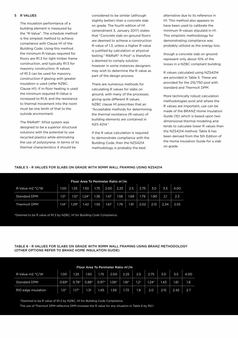
R values calculated using NZS4214
are provided in Table 5. These are
provided for the 215/750 pod with
standard and ThermoX DPM.
More technically robust calculation
methodologies exist and where the
R values are important, use can be
made of the BRANZ Home Insulation
Guide (10) which is based upon two
dimensional thermal modeling and
tends to calculate lower R values than
the NZS4214 method. Table 6 has
been derived from the 5th Edition of
the Home insulation Guide for a slab
on grade.
TABLE 5 - R VALUES FOR SLABS ON GRADE WITH 90MM WALL FRAMING USING NZS4214
Floor Area To Perimeter Ratio m2/m
R-Value m2 °C/W 1.00 1.25 1.50 1.75 2.00 2.25 2.5 2.75 3.0 3.5 4.00
Standard DPM 1.0* 1.12* 1.24* 1.36 1.47 1.58 1.69 1.79 1.90 2.1 2.3
ThermoX DPM 1.14* 1.29* 1.42 1.55 1.67 1.79 1.91 2.02 2.13 2.34 2.55
*Deemed to be R value of R1.3 by NZBC, H1 for Building Code Compliance.
TABLE 6 - R VALUES FOR SLABS ON GRADE WITH 90MM WALL FRAMING USING BRANZ METHODOLOGY (OTHER OPTIONS REFER TO BRANZ HOME INSULATION GUIDE)
Floor Area To Perimeter Ratio m2/m
R-Value m2 °C/W 1.00 1.25 1.50 1.75 2.00 2.25 2.5 2.75 3.0 3.5 4.00
Standard DPM 0.69* 0.78* 0.88* 0.97* 1.06* 1.16* 1.2* 1.24* 1.43 1.61 1.8
R10 edge insulation 1.0* 1.17* 1.31 1.45 1.59 1.73 1.9 2.0 2.15 2.42 2.7
*Deemed to be R value of R1.3 by NZBC, H1 for Building Code Compliance.
The use of ThermoX DPM reflective DPM increase the R value for any situation in Table 6 by R0.1.
6 PLUMBING
Various Territorial Authorities have their
own preferences for plumbing details
so always check with the local council.
Two options exist for running
plumbing:
• The pipes are installed in the ground
below the slab and then rise up
through the slab at the desired
location within the building, referred
to as “below slab installation”. This
is the preferred option in most
situations.
• The pipes run within the plane of
the X-Pod® flooring system, referred
to as “in floor installation”.
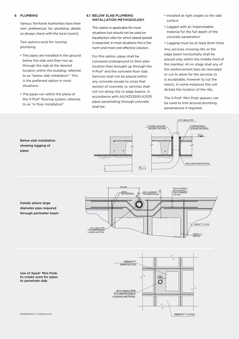
6.1 BELOW SLAB PLUMBING INSTALLATION METHODOLOGY
This option is applicable for most
situations but should not be used on
liquefaction sites for which lateral spread
is expected. In most situations this is the
norm and most cost effective solution.
For this option, pipes shall be
conveyed underground to their plan
location then brought up through the
X-Pod® and the concrete floor slab.
Services shall not be placed within
any concrete except to cross that
section of concrete i.e. services shall
not run along ribs or edge beams. In
accordance with AS/NZS3500.4:2015
pipes penetrating through concrete
shall be:
• Installed at right angles to the slab
surface
• Lagged with an impermeable
material for the full depth of the
concrete penetration
• Lagging must be at least 6mm thick
Any services crossing ribs or the
edge beam horizontally shall be
placed only within the middle third of
the member. At no stage shall any of
the reinforcement bars be relocated
or cut to allow for the services (it
is acceptable, however to cut the
mesh). In some instances this will
dictate the location of the ribs.
The X-Pod® Mini Pods spacers can
be used to trim around plumbing
penetrations if required.
Below slab installation
showing lagging of
pipes
Details where large
diameter pipe required
through perimeter beam
Use of Xpod® Mini Pods to create zone for pipes to penetrate slab.
0.5÷1 %
SEAL DPM PENETRATION
Ø110 (MAX) PIPE
COMPRESSIBLELAGGING MATERIAL
FLEXIBLE SEALANT AROUND THE PIPE
F.F.L.
Illustrations: © Cresco.co.nz
25MIN. CLEARANCEFOR REINFORCING
RIBRAFT™MINIPOD
2HD10BOTTOM BARS
Ø110 (MAX) PIPEIN COMPRESSIBLE
LAGGING MATERIAL
600 MIN.
RIBRAFT™ X-POD
2HD10 CRANKEDBOTTOM BARS +1HD10 CRANKEDTOP BAR
400
Ø110 (MAX) PIPEIN COMPRESSIBLE
LAGGING MATERIAL
RIBRAFT™MINIPOD POD
RIBRAFT™ X-POD
100
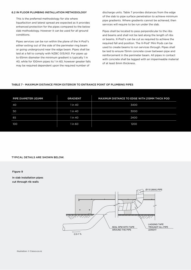
6.2 IN FLOOR PLUMBING INSTALLATION METHODOLOGY
This is the preferred methodology for site where
liquefaction and lateral spread are expected as it provides
enhanced protection for the pipes compared to the below
slab methodology. However it can be used for all ground
conditions.
Pipes services can be run within the plane of the X-Pod®s
either exiting out of the side of the perimeter ring beam
or going underground near the edge beam. Pipes shall be
laid at a fall to comply with NZBC G13/AS1. For pipes up
to 65mm diameter the minimum gradient is typically 1 in
40, while for 100mm pipes its 1 in 60, however greater falls
may be required dependent upon the required number of
discharge units. Table 7 provides distances from the edge
of the slab to pipe surface penetration to achieve minimum
pipe gradients. Where gradients cannot be achieved, then
services will require to be run under the slab.
Pipes shall be located to pass perpendicular to the ribs
and beams and shall not be laid along the length of ribs
or beams. X-Pod®s can be cut as required to achieve the
required fall and position. The X-Pod® Mini Pods can be
used to create beams to run services through. Pipes shall
be laid to ensure 15mm concrete cover between pipe and
reinforcement in the perimeter beam. All pipes in contact
with concrete shall be lagged with an impermeable material
of at least 6mm thickness.
TABLE 7 - MAXIMUM DISTANCE FROM EXTERIOR TO ENTRANCE POINT OF PLUMBING PIPES
PIPE DIAMETER (ID)MM GRADIENT MAXIMUM DISTANCE TO EDGE WITH 215MM THICK POD
40 1 in 40 3400
50 1 in 40 3000
65 1 in 40 2400
100 1 in 60 1200
TYPICAL DETAILS ARE SHOWN BELOW.
Figure 9
In slab installation pipes
cut through rib walls
0.5÷1 %
LAGGING TAPE TROUGHT ALL PIPE LENGHT
Ø110 (MAX) PIPE
SEAL DPM WITH TAPEAROUND THE PIPE
Illustration: © Cresco.co.nz
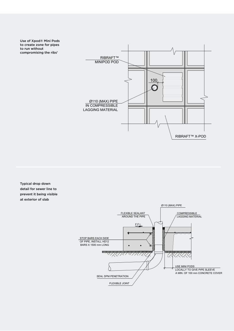
Use of Xpod® Mini Pods to create zone for pipes to run without compromising the ribs’
Typical drop down
detail for sewer line to
prevent it being visible
at exterior of slab
Ø110 (MAX) PIPE
COMPRESSIBLELAGGING MATERIAL
FLEXIBLE SEALANT AROUND THE PIPE
F.F.L.
USE MINI PODSLOCALLY TO GIVE PIPE SLEEVEA MIN. OF 100 mm CONCRETE COVER
SEAL DPM PENETRATION
FLEXIBLE JOINT
STOP BARS EACH SIDE OF PIPE, INSTALL HD12 BARS X 1500 mm LONG
Ø110 (MAX) PIPEIN COMPRESSIBLE
LAGGING MATERIAL
RIBRAFT™MINIPOD POD
RIBRAFT™ X-POD
100
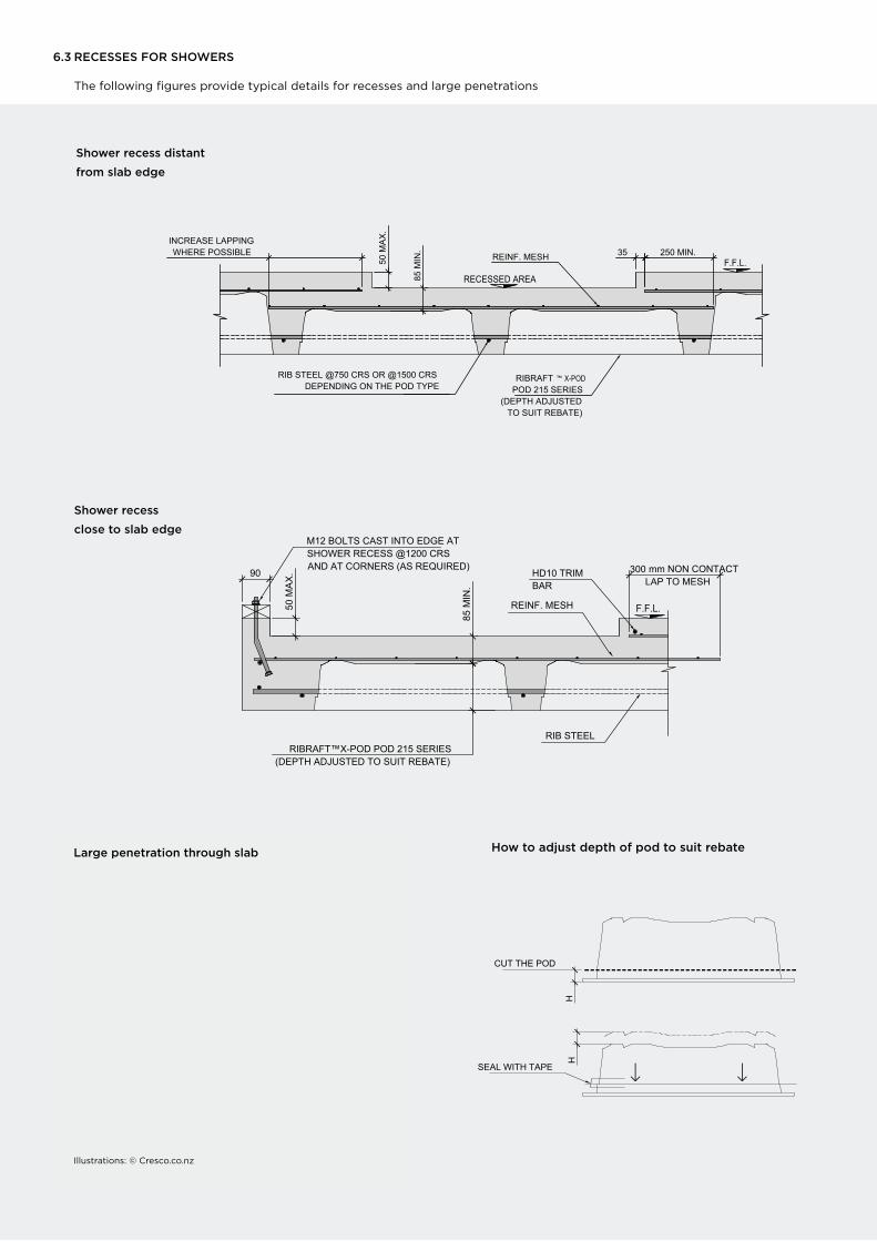
6.3 RECESSES FOR SHOWERS
The following figures provide typical details for recesses and large penetrations
Shower recess
close to slab edge
85 M
IN.
F.F.L.REINF. MESH
HD10 TRIM BAR
RIBRAFT™X-POD POD 215 SERIES(DEPTH ADJUSTED TO SUIT REBATE)
90
M12 BOLTS CAST INTO EDGE AT SHOWER RECESS @1200 CRSAND AT CORNERS (AS REQUIRED) mm NON CONTACT
LAP TO MESH300
50 M
AX
.
RIB STEEL
250 MIN.INCREASE LAPPINGWHERE POSSIBLE
85 M
IN.
RECESSED AREA
F.F.L.REINF. MESH
RIB STEEL @750 CRS OR @1500 CRS DEPENDING ON THE POD TYPE
35
RIBRAFT ™ X-POD POD 215 SERIES
(DEPTH ADJUSTEDTO SUIT REBATE)
50 M
AX
.
Shower recess distant
from slab edge
How to adjust depth of pod to suit rebate
SEAL WITH TAPE
HH
CUT THE POD
Shower recess
close to slab edge
Large penetration through slab How to adjust depth of pod to suit rebate
250 MIN.
INCREASE LAPPING
WHERE POSSIBLE
85
MIN
.
RECESSED AREA
F.F.L.REINF. MESH
RIB STEEL @750 CRS OR @1500 CRS
DEPENDING ON THE POD TYPE
35
RIBRAFT ™X-POD
POD 215 SERIES
(DEPTH ADJUSTED
TO SUIT REBATE)
50
MA
X.
85
MIN
.
F.F.L.REINF. MESH
HD10 TRIM
BAR
RIBRAFT™X-POD POD 215 SERIES
(DEPTH ADJUSTED TO SUIT REBATE)
90
M12 BOLTS CAST INTO EDGE AT
SHOWER RECESS @1200 CRS
AND AT CORNERS (AS REQUIRED) mm NON CONTACT
LAP TO MESH
300
50
MA
X.
RIB STEEL
SEAL WITH TAPE
HH
CUT THE POD
6.3 RECESSES FOR SHOWERS
The following figures provide typical details for recesses and large penetrations
Shower recess distant
from slab edge
Illustrations: © Cresco.co.nz
FIRTH RIBRAFT® X-POD® STRUCTURAL DESIGNERS GUIDE16
7 FINISH FLOOR LEVEL ABOVE GROUND
The finished floor level shall ensure that the height above
ground level satisfies the greater requirements of:
• E1/AS1, refer section 2 in particular
• E2/AS1, refer section 9.1 in particular
• Any local flood management clearance criteria
8 DESIGN DOCUMENTATION
Designers shall provide drawings, calculations, PS1,
Memorandum from a LBP, and a schedule of required
inspections for consent applications.
Drawings shall ensure that the following notes are provided
in addition to the engineers standard notes:
• RibRaft® X-Pod®s, and keystones shall be provided by Firth
Industries.
• All concrete shall be either 20MPa or 25MPa dependent
upon NZS3604 durability zone. Firth mix code IP2519X or
IP2019X shall be used, no substitution shall be allowed.
• All Reinforcing bars shall be Grade 500E and comply with
AS/NZS4671.
• All mesh shall be Grade 500E preferably supplied by
Fletcher Reinforcing. Class L mesh can be used for design
solutions were liquefaction or expansive clays are not a
consideration.
• Where specified Firth HotEdge® shall be installed in
accordance with manufactures instructions and supplied
by Firth industries.
• Construction shall be by installers familiar with residential
floor constructions.
9 REFERENCES
1 Foundation Engineering Handbook, Winterkorn, Fang
2 Analyses of Multi-edge footings resisted on loose and
dense sand, Davarci, Ornek, Turedi
3 Guidance on Repairing and rebuilding houses affected
by the Canterbury Earthquake, MBIE
4 AS2870 Residential Slabs and Footing Construction.
5 NZS3101 - Concrete Structures Standard
6 Walsh, 1978, Technical Research Paper - The analysis of
stiffened rafts on expansive clays
7 Mitchel,1984, A simple method of design of shallow
foundations on expansive soil
8 BRANZ Study report 120- Soil expansivity in the
Auckland Region
9 Li, University of South Australia, 1996, Analysis and
Performance of Footings on expansive Soils
10 Branz, 2014, Home Insulation Guide Fifth Edition
11 Ishihara, K., 1985. “Stability of natural soil deposits
during earthquakes”. International Conference on Soil
Mechanics and Foundation Engineering, San Francisco:
321-376
12 Van Ballegooy, S. et al., 2014. “Assessment of
liquefaction-induced land damage for residential
Christchurch”. Earthquake Spectra, 30(1): 31-35
© Firth Industries 2018. All rights reserved. Content in this document is protected under the Copyright Act 1994. No material may be reproduced in whole or in part without the written consent of the copyright holder.
7 FINISH FLOOR LEVEL ABOVE GROUND
The finished floor level shall ensure that the height above
ground level satisfies the greater requirements of:
• E1/AS1, refer section 2 in particular
• E2/AS1, refer section 9.1 in particular
• Any local flood management clearance criteria
8 DESIGN DOCUMENTATION
Designers shall provide drawings, calculations, PS1,
Memorandum from a LBP, and a schedule of required
inspections for consent applications.
Drawings shall ensure that the following notes are provided
in addition to the engineers standard notes:
• RibRaft® X-Pod®s, and keystones shall be provided by
Firth Industries.
• All concrete shall be either 20MPa or 25MPa dependent
upon NZS3604 durability zone. Firth mix code IP2519X or
IP2019X shall be used, no substitution shall be allowed.
• All Reinforcing bars shall be Grade 500E and comply with
AS/NZS4671.
• All mesh shall be Grade 500E preferably supplied by
Fletcher Reinforcing. Class L mesh can be used for design
solutions were liquefaction or expansive clays are not a
consideration.
• Where specified Firth HotEdge® shall be installed in
accordance with manufactures instructions and supplied
by Firth industries.
• Construction shall be by installers familiar with residential
floor constructions.
9 REFERENCES
1 Foundation Engineering Handbook, Winterkorn, Fang
2 Analyses of Multi-edge footings resisted on loose and dense sand, Davarci, Ornek, Turedi
3 Guidance on Repairing and rebuilding houses affected by the Canterbury Earthquake, MBIE
4 AS2870 Residential Slabs and Footing Construction.
5 NZS3101 - Concrete Structures Standard
6 Walsh, 1978, Technical Research Paper - The analysis of stiffened rafts on expansive clays
7 Mitchel,1984, A simple method of design of shallow foundations on expansive soil
8 BRANZ Study report 120- Soil expansivity in the Auckland Region
9 Li, University of South Australia, 1996, Analysis and Performance of Footings on expansive Soils
10 Branz, 2014, Home Insulation Guide Fifth Edition
11 Ishihara, K., 1985. “Stability of natural soil deposits during earthquakes”. International Conference on Soil Mechanics and Foundation Engineering, San Francisco: 321-376
12 Van Ballegooy, S. et al., 2014. “Assessment of liquefaction-induced land damage for residential Christchurch”. Earthquake Spectra, 30(1): 31-35
0800 FIRTH 1 (347841)FIRTH.CO.NZ productspec.net
PRODUCTSPEC
© Firth Industries 2018. All rights reserved. Content in this document is protected under the Copyright Act 1994. No material may be reproduced in whole or in part without the written consent of the copyright holder.
masterspec.co.nz