structural design &optimization of an unmanned aerial ... · uav, structural design,...
TRANSCRIPT

Volume 5, Issue 1 (2017) 24-29 ISSN 2347 - 3258
International Journal of Advance Research and Innovation
24 IJARI
Structural Design &Optimization Of An Unmanned Aerial Vehicle Wing
For SAE Aero Design Challenge Harsh Raj Chauhan*, Harsh Panwar*, Vikas Rastogi Department of Mechanical Engineering, Delhi Technological University (Formerly DCE), New Delhi-110042, India
Abstract Aircraft design is a multi-disciplinary iterative design process which follows a Systems Engineering
approach and Unmanned Aerial Vehicle design follows one such design methodology. This paper is
an attempt to formulate the structural design process for a UAVwing and subsequent optimizationfor
SAE India Aero Design Challenge 2017.The design starts with the identification of structural design
parameters and challenge requirements in the Pre-design/Conceptual Design phase. Based on the
engineering values, a mathematical interface is coded in MATLAB to calculate the mechanical
equivalents for the wing at individual sections and to prepare an internal structural layout adhering
to the selected material properties. The structural design of the wing is then modelled in Solidworks
and final mass is calculated in the Preliminary Design phase. For initial estimates, the static
structural analysis of the layout is performed theoretically.The final design of the wing is then fed in
ANSYS Finite Element Solver for Static Structural analysis. Now, successive iterations are
performed for the optimization of a critical structural parameter with bound constraints directly
affecting the mass of the structure using MATLAB in the Detailed Design phase. The optimized
version is then finally validated.
1. Introduction SAE Aero Design Challenge 2017 is a UAV design challenge to be
held in March 2017 in India. The competition aims at maximizing
the payload carrying capacity of the UAV while completing a full
circuit of the airfield. The constraint of maximizing the payload of
the UAV directly influences the engineering design of the wing of
the UAV since wings prove to be an important subsystem which
provide both aerodynamic worth and structural integrity to the
UAV. It therefore calls for the design and analysis of wings
carefully engineered so as to cater to the requirements of the
challenge.An attempt has been made through this research, to
comply by the requirements as close as possible while reaching
towards an optimized version of the wing. Any research work is
never complete since there is always a scope for better solutions as
we progress and touch newer domains.The focus of this research is
limited to the structural design and optimization of the wing of the
unmanned aerial vehicle only, although, other subsystems of the
UAV were designed and developed too. Following is the design
methodology developed for this research work.
2.Conceptual Design Phase The design process of the wing starts with the identification of
critical structural design inputs that are derived from the set of
competition requirements which are fed into MATLAB for further
mathematical modelling.
2.1 Structural Design Inputs The structural design inputs were derived by identifying the most
influential parameter from the set of design parameters for the
competition. The payload capacity proved to be the most influential
parameter and was taken as the basis for further design of the wing.
The corresponding starting value for the influential parameter was
taken as 5g ie. the designed wings should be able to sustain 5 times
its own weight without structural failure. The other structural
parameters like exposed wing area, root chord and tip chord were
calculated during the aircraft design and have not been included in
this research. The design factor of 1.5 has been taken for maximum
reliability of around 99%. The wing airfoil for the aircraft was taken
as Selig 1210.
*Corresponding Author,
E-mail address:[email protected]; Phone No-+91-
9818886652; [email protected]; Phone No-+91-
9891197447
All rights reserved: http://www.ijari.org
3.Preliminary Design Phase The preliminary design phase starts with mathematical modelling of
the structural design in MATLAB. The design method adopted has
been displayed in a flowchart in figure 2.
3.2Structural Sizing The developed mathematical model is now run in MATLABas a
live script. The code initiates with a prompt command where it asks
the user to enter 13 values and the code then calculates the rest of
the variables as described in the flowchart.
After dividing the wing into number of divisions, the location of
center of pressure is taken as well as the position of the front spar
and the rear spar.
Center of Pressure= 45% of chord length from the leading edge
Front spar position= 25% of chord length
Rear spar position = 62% of chord length
Further sizing of the wing components were done keeping into
consideration the maximum values of shear force and bending
moment distribution on the spars.
Maximum Bending moment=78384 N-mm
Maximum shear force = 85.1575 N
Material for front spar= AA 6061 T-6
Material for rear spar= Birchwood
Volume of front spar = 45555 mm^3
Volume of rear spar= 67767 mm^3
Total volume= 113322 mm^3
Total mass of the spars= 316.1701 gms
3.3 Performance Charts After the mathematical model displayed and stored the mechanical
values for the wing, performance charts were plotted on MATLAB
for variables as a function of the chord length at each section from
tip to root for both the front and rear spars. The following plot
shows the variation of shear force due to torsion and the total shear
force as a function of chord length.
3.4 Initial Blueprint
The obtained wing design from the mathematical model is then
modelled in Solidworks for further analysis in the detailed design
phase.
Article Info
Article history:
Received 16 February 2017
Received in revised form
16 February 2017
Accepted February 2017
Available online March 2017
Keywords
UAV, Structural Design,
Optimization, MATLAB

Volume 5, Issue 1 (2017) 24-29 ISSN 2347 - 3258
International Journal of Advance Research and Innovation
25 IJARI
Fig.1 Design Methodology
Table 1 Competition Requirements
S.No Design Parameter Objective
1. Time Limit < 180 sec
2. Take-off distance < 400 feet
3. Landing Distance < 400 feet
4. GTOW (excluding payload) < 5 kgs
5. Payload Maximise
Mathematical Modelling (Matlab)
Fig.2 Mathematical Modelling flowchart
Fig.3 User I/O live script in MATLAB to input design parameters
Table 2. Derived structural parameters
S.No Structural Parameter Value/Range
1. Root chord/Tip Chord 380/230 mm
2. Exposed span 2000 mm
3. Aircraft weight <= 50N
4. Lift Load 5g
5. Design Factor 1.5
6. Exposed wing area 726000 mm^2
Conceptual Design Preliminary Design Detailed Design
Mathematical interface in
MATLAB
3D modelling of the calculated
wing structure
Derived structural design
parameters from competition
requirements
Theoretical structural analysis
Finite Element Analysis
Structural Optimization
Structural Design Inputs fed into
MATLAB
1) Limit Load calculation
2) Design Load calculation
3) Pressure Load calculation
Divide the wing into number of
sections and calculate:
1) Chord length
2) Center of gravity
3) Shear force & Bending moment
Load Distribution on the wing:
Estimate: 1) Center of Pressure
2) Front & Rear spar position
Calculate:
1) Shear Force Distribution
2) Bending moment distribution
shared by front & rear spar.
Enter material properties for spar:
1)Ultimate Tensile strength
2)Shear strength
3)Young’s modulus, Poisson’s Ratio
Calculate:
1) Moment of inertia of front
& rear spar.
Design a Torque Box between
the front & rear spar. Calculate:
1)Center of gravity of the box
2)Torque & Shear flow
Decide the shape & cross-section of
the front and rear spar. Calculate:
1)Area of web & moment of inertia
2)Moment of inertia of flange and
subsequent area of flange.
Calculate:1)Total area of spars
2)Total Volume of spars
3)Mass of the spars

Volume 5, Issue 1 (2017) 24-29 ISSN 2347 - 3258
International Journal of Advance Research and Innovation
26 IJARI
Fig.4 Chord length calculations by dividing the wing into number of
sections
Fig.5 Cumulative shear force calculation
Fig.6 Bending moment calculation
Table 3. Shear Force & Bending moment distribution on the
front and rear spar
Sections on the
wing
(mm)
Chord length at
each section
(mm)
Shear Force on
front spar
(N)
Bending Moment
on front spar
(N-mm)
Shear Force on
rear spar
(N)
Bending
Moment on rear
spar
(N-mm)
TIP-1127 230 - - - -
S1-1014.3 245 5.6364 569 6.6311 671
S2-901.6 260 11.6289 2300 13.6810 2711
S3-788.9 275 17.9773 5263 21.1498 6204
S4-676.2 290 24.6817 9531 29.0373 11234
S5-563.5 305 31.7421 15174 37.3436 17884
S6-450.8 320 39.1585 22262 46.0688 26240
S7-338.1 335 46.9308 30869 55.2128 36383
S8-225.4 350 55.0592 41063 64.7755 48399
S9-112.7 365 63.5435 52918 74.7571 62371
ROOT-0 380 72.3839 66503 85.1575 78384
Table 4. Moment of inertia of spars; Torque box design, cumulative torque and shear flow on wing
Sections on the wing
(mm)
Moment of
inertia of front
spar
(mm^4)
Moment of
inertia of rear
spar
(mm^4)
CG of torque box
from rear spar
position (mm)
Cumulative
Torque
(N-mm)
Shear Flow
(N/mm)
TIP-1127 - - 0 - -
S1-1014.3 23.3 21.6 47.122 67.1 0.0163
S2-901.6 94.2 87.4 50.007 214.1 0.0490
S3-788.9 215.6 200.1 52.8921 454.4 0.0984
S4-676.2 390.5 362.4 55.7771 802.4 0.1647
S5-563.5 621.6 576.9 58.6621 1273 0.2485
S6-450.8 912 846.4 61.5471 1882.1 0.3501
S7-338.1 1264.6 1173.7 64.4322 2646.4 0.4703
S8-225.4 1682.3 1561.3 67.3172 3583.1 0.6095
S9-112.7 2167.9 2012 70.2022 4710.6 0.7683
ROOT-0 2724.5 2528.5 73.0872 6047.7 0.9474
Table 4. Moment of inertia of spars; Torque box design, cumulative torque and shear flow on wing

Volume 5, Issue 1 (2017) 24-29 ISSN 2347 - 3258
International Journal of Advance Research and Innovation
27 IJARI
Fig.7 Moment of inertia calculation
Fig.8 Torque box area calculation
Table 5. Moment of inertia of web
Sections on
the wing
(mm)
Moment of inertia of
web for front spar
(mm4)
Moment of inertia
of web for rear
spar (mm4)
TIP- 11227 0 0
S1-1014.3 1.5715 1.1203
S2-901.6 3.3437 2.3069
S3-788.9 5.3181 3.7226
S4-676.2 7.4971 5.2064
S5-563.5 9.8834 6.8137
S6-450.8 12.4804 8.5461
S7-338.1 15.2916 10.4055
S8-225.4 18.3209 12.3936
S9-112.7 21.5724 14.5125
ROOT-0 25.0502 16.7643
Fig.9 Shear Force due to torsion; Total shear in front spar
Fig.10 Shear Force due to torsion; Total shear in rear spar
Fig.11 Internal structure of the wing (Isometric View)
Fig.12 Internal structure of the wing (Top View)
Table 6. Mechanical Parameter values for spar
STRUCTURAL PARAMETERS VALUE
Max Principal stress 83.2 Mpa
Max Von-Mises stress 56.2 MPa
Max Strain Energy 8.04e9 J
Max equivalent elastic strain .00079
Total deformation 7 mm
Yield strength of AA 6061 T-6 310 MPa
Safety factor 3.73
Volume 5, Issue 1 (2017) 24-29 ISSN 2347 - 3258
International Journal of Advance Research and Innovation
28 IJARI
4.Detailed Design Phase The detailed design phase starts with the analysis of the initial
blueprint of the wing using some initial hand calculations and Finite
Element solver like ANSYS. The results are then optimized for
appropriate weight reduction.
The structural optimization flowchart is as follows. The whole
process is an iterative one, ie. Iterations keep taking place till we get
the optimized result.
4.1 Detailed Design Flowchart
Fig.13 Structural optimization flowchart
The flowchart shown as figure 13, terminates at the point in
MATLAB when, for a particular value of a/b and web thickness, the
mass reduces and subsequently gets verified through Finite Element
solver ie. ANSYS through stress and strain contour plots with a
significant reduction in a value.
4.2 Finite Element Analysis Finite Element Analysis is a computerized method which is used to
predict the behavior of a mechanical model in response to an
applied force, provided a set of boundary conditions. The modelled
wing on Solidworks is now analyzed in ANSYS, a finite element
solver when the wing is exposed to various mechanical forces of
varying magnitudes. The material properties for the ribs was added
in ANSYS for balsawood and birchwood
Fig.14 Failed & Obsolete Mesh (1st attempt)
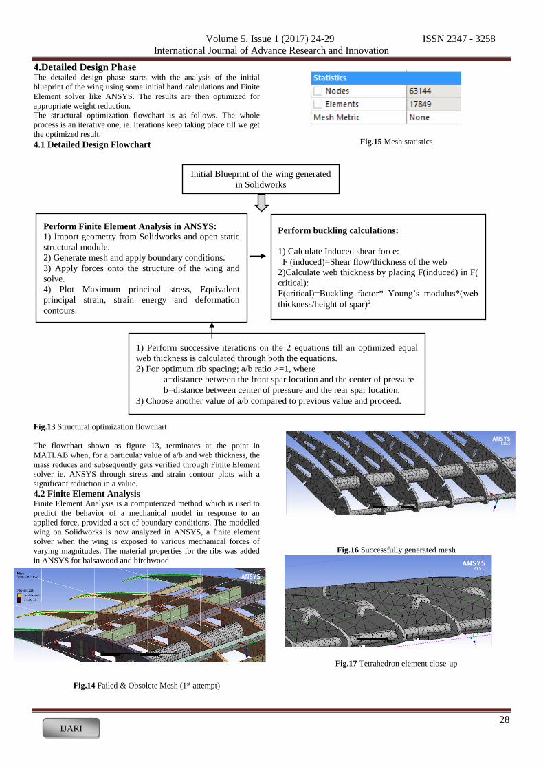
Fig.15 Mesh statistics
Fig.16 Successfully generated mesh
Fig.17 Tetrahedron element close-up
Initial Blueprint of the wing generated
in Solidworks
Perform buckling calculations:
1) Calculate Induced shear force:
F (induced)=Shear flow/thickness of the web
2)Calculate web thickness by placing F(induced) in F(
critical):
F(critical)=Buckling factor* Young’s modulus*(web
thickness/height of spar)2
Perform Finite Element Analysis in ANSYS:
1) Import geometry from Solidworks and open static
structural module.
2) Generate mesh and apply boundary conditions.
3) Apply forces onto the structure of the wing and
solve.
4) Plot Maximum principal stress, Equivalent
principal strain, strain energy and deformation
contours.
1) Perform successive iterations on the 2 equations till an optimized equal
web thickness is calculated through both the equations.
2) For optimum rib spacing; a/b ratio >=1, where
a=distance between the front spar location and the center of pressure
b=distance between center of pressure and the rear spar location.
3) Choose another value of a/b compared to previous value and proceed.

Volume 5, Issue 1 (2017) 24-29 ISSN 2347 - 3258
International Journal of Advance Research and Innovation
29 IJARI
Fig.18 Force application on the wing
Fig.19 Equivalent Von-Mises stress contours
Fig.20 Strain energy contours
Fig.21 Equivalent Von-mises stress contours in spar
When the CAD model of the wing was first imported in ANSYS
and the mesh was generated, the mesh failed at certain contact
points of the assembly, shown by red blips in Fig.12. It was
observed that the meshing method was not accurate and the element
size was large at thin trailing edges which led to failure at such
points. The meshing method was then changed to Tetrahedron
elements with a Patch Independent algorithm limited by maximum
element size. The mesh was then generated successfully.
The meshed wing is now opened in ANYS Mechanical and 4
types of force are applied onto the entire structure 1) Uniformly varying load on the front supporting spar
2) Uniformly varying load on the primary AA 6061 T-6 spar
3) Moment along the transverse axis of the wing
4) Standard earth gravity on all bodies
Table 7. Mechanical Parameter values for the internal structure
Table 8. Weight optimization by changing the position of front spar,
keeping rear spar fixed
Iter
atio
n
Position of
front spar
from
leading
edge
Position of
rear spar
from
leading
edge
a/b
ratio
Total
mass of
the spars
(gm)
1 25 % 62% 1.17647 316.71
2 22% 62% 1.353 310.55
3 20% 62% 1.4706 302.88
4 18% 62% 1.588 299.25
5 30 % 62 % 0.8823 323.10 s
By shifting the position of the front spar ie. Increasing a/b ratio, a
maximum reduction of 17.46 gms was achieved, but the placement
of spar was not feasible at 18% chord. Hence, the placement of spar
at 22% chord was finally selected with the total mass of spars
equaling 310.55 gms.
5. Conclusions The paper demonstrates the design methodology undertaken in the
structural design and optimization of a UAV wing for the SAE India
Aero Design Challenge 2017. The final analysis and calculations
can be accepted of a structurally fit pair of wings for the UAV. The
most influential parameter of the competition ie. Payload capacity
seems to be fulfilled through this design, as the wing is designed for
a lift load factor of 5. The final simulation on the wing also gave us
a safety factor of 3.73 which validates it completely.
References [1] Bruhn EF. Analysis & design of flight vehicle structures. 1 ed.
USA: Tri-state offset company, 1973.
[2] Sadraey M., Aircraft Design: A Systems Engineering Approach,
2012, Wiley Publications
[3] UAVs: An Overview, Peter van Blyenburgh, Air & Space
Europe 1(5/6) – 1999
[4] Raymer DP. Aircraft Design: A Conceptual Approach,
American Institute of Aeronautics and Astronautics, Washington
D.C, 1992
[5] Roskam J. Airplane Design, Roskam Aviation and Engineering
Corporation, 1985
[6] Bruno Jorge, Pereira Cadete: Aero-Structural Optimization of
Sailplane Wings, Sintra, December 2011
STRUCTURAL PARAMETERS VALUE
Max principal stress 68 MPa
Max Von-Mises stress 70 MPa
Max strain energy 30 mJ
Max equivalent elastic strain 0.139 mJ
Normal stress 17.87 MPa
Total deformation 11.8 cm