stronger than steel sm - clarkdietrich.com · the prostud drywall framing system provides peace of...
TRANSCRIPT

S T R O N G E R T H A N S T E E LSM.
ProSTUD® product catalog
D R Y WA L L F R A M I N G S Y S T E M

W H E R E I N N O V A T I O N T A K E S F O R M.
Clark Dietrich.
P r o S T U D® D R Y W A L L F R A M I N G S Y S T E M

TABLE OF CONTENTS
ProSTUD Drywall Framing System Table of Contents 3
Overview 4
Profile Information 5
Physical & Structural Properties ProSTUD 25 (15mil) 6
ProSTUD 20 (18 mil) 7 ProSTUD 20 LTD (19mil) 8 ProSTUD 30MIL 9 ProSTUD 33MIL 10
Connections Allowable Screw Design Values 11
Limiting Heights Overview 12
Composite Limiting Heights Tables 13–14
Non-Composite Limiting Heights Tables Fully Braced 15 Braced at 48" o.c. 16
Sound Testing Sound Assemblies 17–18
Fire Testing UL® Listed Wall Assemblies 19
Connections Deflection Track Systems 20
Ceiling Span Tables 21
General LEED® Information 22 Support Tools 23
Code Compliance and Certification 24
The ProSTUD® Drywall Framing System can be called many things. Strong. Versatile. Fast. And without a doubt—revolutionary. But one of the biggest benefits to keep in mind is this: ProSTUD was developed, tested and approved by pros in the field who demanded nothing less than achieving absolute ease of use. Its performance has also been proven by the most extensive laboratory evaluations available. All of which means ProSTUD comes with complete confidence and no questions about code compliance. With the backing of online, mobile and data-rich BIM resources, there’s no better example of a broader vision at work.
ProSTUD, in fact, is just one example of how ClarkDietrich can reinforce your efforts to design and build more intelligently. Yes, we’re known as a manufacturer of extensively tested, code-compliant steel framing products, but we offer so much more. Our products perform as a system. We support a range of efforts for smarter installation and design. We
provide the expertise of a versatile engineering services team. And we do it all on a nationwide scale.
We’ve put together an incredible array of resources to help you be successful on any project, regardless of size or complexity. Within this catalog you’ll discover the multiple advantages ProSTUD has to offer, as well as detailed information on the product lineup, limiting heights, sound and fire assemblies, and more.
Ultimately, your choice of ProSTUD doesn’t come down to the integrity of the product alone, or even its ease of use. You’re also looking to the strength of the company that stands behind it. Count on the expertise, services and full support of ClarkDietrich today—and far into the future.
Need Product Submittals? Use SubmittalPro® at clarkdietrich.com.
3

The technical content of this literature is effective 6/25/18 and supersedes all previous information.Pub. No. CD-ProSTUD 6/18 clarkdietrich.com
Allowable Bending Capacity, 3-5/8" Stud
O V E R V I E W
Gauge equivalent drywall framing must meet the minimum performance requirements of conventional drywall framing as defined by the Steel Framing Industry Association (SFIA) and the Steel Stud Manufacturers Association (SSMA). The industry’s “EQ” product of choice, ProSTUD,® employs roll-forming and steel-making technology, exceeding the performance of conventional drywall framing for allowable moment and screw connection strength. When comparing drywall framing systems, it is important to keep in mind Life Safety, System Performance and Connections. The ProSTUD Drywall Framing System provides peace of mind for all three important functions by providing the right selection of products and product data for every application.
ConnectionsIn addition to sufficient member strength, it’s important to know how connections will perform. Connections can be critical to the capacity and safety of an assembly, but they are also important for the attachment of cabinets, shelving, handrails, and other accessories to steel framing. The tables below compare the screw performance of ProSTUD to conventional drywall framing. This performance relationship to conventional studs can be applied to a variety of fasteners and connections.
Along with connection capacity, conventional framing members are required to meet performance criteria for screw spinout. ProSTUD was developed with screw performance in mind. High-strength steel, flange stiffening grooves, web embossments, and knurling features combine to provide the best performance per thickness, exceeding the requirements of ASTM C645.
Life SafetyLife Safety is the primary concern and duty of all construction and design professionals. For interior drywall framing members, bending strength is the criteria most important to the strength of a wall or ceiling. AISI defines bending or flexural strength by Allowable Moment. The corresponding chart compares the bending strength of ProSTUD and conventional drywall studs.
System PerformanceGiven ProSTUD’s strength and versatility, it’s important to know the performance of the ProSTUD member under your project’s specific criteria. This catalog will provide guidance in a variety of assemblies and loading criteria, based on current building codes. Additional data is available at clarkdietrich.com. Al
lowab
le M
omen
t (M
a, in
-k)
ProS
TUD
25
ProS
TUD
20
25 G
auge
20 G
auge
(Dry
wal
l)
4
3
21.69
3.10
1.48
3.08
1
0
W H A T I S A N E Q U I V A L E N T ( E Q ) D R Y W A L L S T U D ?
Comparison of ProSTUD Drywall Framing to Conventional Drywall Framing
#6 Screw Shear (Bearing) Values
Allow
able
Shea
r (lb
s)
ProS
TUD
25
0
60
90
120
30
31
#6 Screw Pullout Values
Allow
able
Pullo
ut (l
bs)
ProS
TUD
25
ProS
TUD
20
25 G
auge
60
0
45
30
15
20 G
auge
(Dry
wal
l)
ProSTUD Drywall Framing Conventional Drywall FramingProSTUD 25 15mil 25 Gauge 18milProSTUD 20 18mil 20 Gauge 30mil
24
52
40
52
25 G
auge
95
44
95
ProS
TUD
20
20 G
auge
(Dry
wal
l)
4

The technical content of this literature is effective 6/25/18 and supersedes all previous information. The technical content of this literature is effective 6/25/18 and supersedes all previous information. Pub. No. CD-ProSTUD 6/18clarkdietrich.com
• Web Widths: 1-5/8," 2-1/2," 3-1/2," 3-5/8," 4," 5-1/2," and 6"• Flange: 1-1/4"• Return Lip: varies by stud size • Material Thicknesses:
ProSTUD 25 / 15mil (25ga EQ) 50ksi ProSTUD 20 / 18mil (20ga EQ) 70ksi ProSTUD 30MIL 33ksi ProSTUD 33MIL 33ksi
• Available G40EQ, G40 (CP60 available as special order)• G40EQ DiamondPlus™ available for 15mil, 18mil & 19mil only.• ProS TUD 20 LTD / 19mi l (65 k s i ) Ava i l ab le for l imite d t ime.Contact your ClarkDietrich Sales Representative for market availability.
• Web Widths: 1-5/8," 2-1/2," 3-1/2," 3-5/8," 4," 5-1/2," and 6"• Legs: 1," 1-1/4," 1-1/2," 2," 2-1/2," and 3"• Material Thicknesses:
ProTRAK 25 / 15mil (25ga EQ) 50ksi ProTRAK 20 / 18mil (20ga EQ) 50ksi ProTRAK 30MIL 33ksi ProTRAK 33MIL 33ksi
• Available G40EQ, G40 (CP60 available as special order)• G40EQ DiamondPlus™ available for 15mil, 18mil & 19mil only.• ProTR AK 20 LTD / 19mi l (65 k s i ) Ava i l ab le for l imite d t ime.Contact your ClarkDietrich Sales Representative for market availability.
ProSTUD Profile
Double offset web planking
Diamond- embossed web*
Return lips vary depending on stud sizeLow-profile flange stiffening grooves
Drywall Joint
Flange grooves spaced at 3/8" o.c.
3/8" Minimum edge distance
Double offset in web prevents flange locking of studs
Shipping / Stacking
P R O F I L E I N F O R M A T I O N
ProS TUD ®
ProTR AK
CO N S T R U C T I O N A DVA N TAG E S D E S I G N A DVA N TAG E S
*Except in 1-5/8"
Can contribute LEED® points in LEED v4 or LEED 2009. EPD and HPD verifications also available
•
Designed to meet the additional strength requirements of today's building codes: IBC 2015, AISI NASPEC (S100), ICC-ES AC86 (2015)
•
National availability•
5

The technical content of this literature is effective 6/25/18 and supersedes all previous information.Pub. No. CD-ProSTUD 6/18 clarkdietrich.com
P H Y S I C A L A N D S T R U C T U R A L P R O P E R T I E S
ClarkDietrich ProTRAK 25 (15mil) physical and structural properties
MemberDesign
thickness (in)
Fy (ksi)
Gross Section Properties Effective Section Properties at Fy Torsional PropertiesArea(in2)
Weight(lb/ft)
Ix(in4)
Rx(in)
Iy(in4)
Ry(in)
Ae(in2)
Ix(in4)
Sx(in3)
Ma(in-lbs)
Vag(lb)
Jx1000(in4)
Cw(in6)
Xo(in)
Ro(in)
βBeta
162PDT125-15 0.0158 50 0.065 0.22 0.034 0.717 0.011 0.412 0.020 0.021 0.016 464 222 0.00542 0.006 -0.881 1.208 0.468
250PDT125-15 0.0158 50 0.079 0.27 0.085 1.038 0.013 0.400 0.020 0.059 0.024 724 143 0.00657 0.015 -0.771 1.353 0.675
362PDT125-151 0.0158 50 0.097 0.33 0.196 1.425 0.014 0.381 0.021 0.125 0.035 1059 98 0.00805 0.034 -0.668 1.619 0.830
400PDT125-151 0.0158 50 0.103 0.35 0.247 1.550 0.014 0.374 0.021 0.153 0.039 1171 89 0.00854 0.043 -0.640 1.718 0.861
600PDT125-152 0.0158 50 0.134 0.46 0.646 2.194 0.016 0.343 0.021 0.350 0.059 1762 59 0.01117 0.108 -0.524 2.282 0.947
162PDT200-15 0.0158 50 0.089 0.30 0.050 0.752 0.039 0.663 0.020 0.025 0.015 455 222 0.00739 0.020 -1.579 1.870 0.287
250PDT200-15 0.0158 50 0.103 0.35 0.124 1.098 0.045 0.662 0.021 0.064 0.024 720 143 0.00854 0.052 -1.431 1.921 0.445
362PDT200-151 0.0158 50 0.120 0.41 0.277 1.516 0.051 0.648 0.021 0.137 0.036 1063 98 0.01002 0.120 -1.282 2.088 0.623
400PDT200-151 0.0158 50 0.126 0.43 0.344 1.650 0.052 0.642 0.021 0.168 0.039 1178 89 0.01052 0.151 -1.240 2.162 0.671
600PDT200-152 0.0158 50 0.158 0.54 0.864 2.338 0.058 0.608 0.021 0.389 0.060 1789 59 0.01315 0.383 -1.058 2.638 0.839
162PDT250-15 0.0158 50 0.105 0.36 0.061 0.766 0.071 0.824 0.020 0.027 0.015 455 222 0.00871 0.038 -2.058 2.345 0.230
250PDT250-15 0.0158 50 0.118 0.40 0.150 1.123 0.082 0.831 0.021 0.066 0.024 725 143 0.00986 0.096 -1.892 2.352 0.353
362PDT250-151 0.0158 50 0.136 0.46 0.330 1.557 0.092 0.823 0.021 0.142 0.036 1073 98 0.01134 0.220 -1.720 2.462 0.512
400PDT250-151 0.0158 50 0.142 0.48 0.409 1.696 0.095 0.819 0.021 0.174 0.040 1189 89 0.01183 0.275 -1.670 2.517 0.560
600PDT250-152 0.0158 50 0.174 0.59 1.009 2.409 0.108 0.787 0.021 0.404 0.060 1809 59 0.01446 0.697 -1.452 2.921 0.753
Notes:– Calculated properties are based on AISI S100-12, North American Specification for Design of Cold-Formed Steel Structural Members and AISI S220-15, North American Standard for
Cold-Formed Steel Framing—Nonstructural Members.– Effective properties incorporate the strength increase from the cold work of forming as applicable per AISI A7.2.– Tabulated gross properties, including torsional properties, are based on full-unreduced cross section of the studs, away from punchouts. – Tabulated gross properties, including torsional properties, are based on full-unreduced cross section of the tracks.– For deflection calculations, use the effective moment of inertia.– Allowable moment includes cold work of forming.– Allowable moment is taken as the lowest value based on local or distortional buckling. Distortional buckling strength is based on a k-phi = 0. – Web depth for track sections is equal to the nominal height plus two times the design thickness plus the bend radius. Hems on nonstructural track sections are ignored.1 Web-height to thickness ratio exceeds 200.2 Web-height to thickness ratio exceeds 260.
ProT R A K® 2 5 ( 1 5 M I L ) D R Y W A L L T R A C K
ClarkDietrich ProSTUD 25 (15mil) physical and structural properties
MemberDesign
thickness (in)
Fy (ksi)
Gross Section Properties Effective Section Properties at Fy Torsional PropertiesLu (in)Area
(in2)Weight(lb/ft)
Ix(in4)
Rx(in)
Iy(in4)
Ry(in)
Ae(in2)
Ix(in4)
Sx(in3)
Ma(in-lbs)
Vag(lb)
Vanet(lb)
Jx1000(in4)
Cw(in6)
Xo(in)
Ro(in)
βBeta
162PDS125-15 0.0158 50 0.071 0.24 0.033 0.688 0.015 0.466 0.033 0.030 0.024 719 232 104 0.00589 0.009 -1.088 1.369 0.368 24.8
250PDS125-15 0.0158 50 0.085 0.29 0.088 1.020 0.018 0.459 0.033 0.080 0.044 1198 147 141 0.00704 0.023 -0.959 1.473 0.576 24.5
362PDS125-151 0.0158 50 0.102 0.35 0.206 1.420 0.020 0.442 0.034 0.190 0.056 1689 100 100 0.00852 0.051 -0.837 1.706 0.760 24.3
400PDS125-151 0.0158 50 0.108 0.37 0.260 1.549 0.021 0.436 0.034 0.233 0.062 1870 90 90 0.00901 0.064 -0.803 1.798 0.800 24.2
600PDS125-152 0.0158 50 0.140 0.48 0.683 2.209 0.023 0.404 0.034 0.537 0.105 2781 60 60 0.01164 0.161 -0.666 2.343 0.919 23.6
ProS T U D® 2 5 ( 1 5 M I L ) D R Y W A L L S T U D
6

The technical content of this literature is effective 6/25/18 and supersedes all previous information. The technical content of this literature is effective 6/25/18 and supersedes all previous information. Pub. No. CD-ProSTUD 6/18clarkdietrich.com
P H Y S I C A L A N D S T R U C T U R A L P R O P E R T I E S
ClarkDietrich ProSTUD 20 (18mil) physical and structural properties
ClarkDietrich ProTRAK 20 (18mil) physical and structural properties
Notes:– Calculated properties are based on AISI S100-12, North American Specification for Design of Cold-Formed Steel Structural Members and AISI S220-15, North American Standard for
Cold-Formed Steel Framing—Nonstructural Members.– Effective properties incorporate the strength increase from the cold work of forming as applicable per AISI A7.2.– Tabulated gross properties, including torsional properties, are based on full-unreduced cross section of the studs, away from punchouts. – Tabulated gross properties, including torsional properties, are based on full-unreduced cross section of the tracks.– For deflection calculations, use the effective moment of inertia.– Allowable moment includes cold work of forming.– Allowable moment is taken as the lowest value based on local or distortional buckling. Distortional buckling strength is based on a k-phi = 0. – Web depth for track sections is equal to the nominal height plus two times the design thickness plus the bend radius. Hems on nonstructural track sections are ignored.1 Web-height to thickness ratio exceeds 200.2 Web-height to thickness ratio exceeds 260.
MemberDesign
thickness (in)
Fy (ksi)
Gross Section Properties Effective Section Properties at Fy Torsional PropertiesArea(in2)
Weight(lb/ft)
Ix(in4)
Rx(in)
Iy(in4)
Ry(in)
Ae(in2)
Ix(in4)
Sx(in3)
Ma(in-lbs)
Vag(lb)
Jx1000(in4)
Cw(in6)
Xo(in)
Ro(in)
βBeta
162PDT125-18 0.0190 50 0.078 0.27 0.040 0.718 0.013 0.411 0.028 0.027 0.022 663 380 0.00943 0.007 -0.879 1.207 0.470
250PDT125-18 0.0190 50 0.095 0.32 0.102 1.038 0.015 0.400 0.029 0.073 0.034 1029 248 0.01143 0.017 -0.770 1.353 0.676
362PDT125-18 0.0190 50 0.116 0.40 0.236 1.426 0.017 0.380 0.029 0.173 0.050 1497 170 0.01400 0.041 -0.666 1.619 0.831
400PDT125-18 0.0190 50 0.123 0.42 0.297 1.550 0.017 0.374 0.029 0.211 0.055 1653 154 0.01486 0.051 -0.638 1.718 0.862
600PDT125-182 0.0190 50 0.161 0.55 0.778 2.195 0.019 0.342 0.029 0.469 0.083 2473 102 0.01943 0.130 -0.523 2.282 0.947
162PDT200-18 0.0190 50 0.107 0.36 0.061 0.753 0.047 0.662 0.028 0.032 0.021 642 380 0.01285 0.024 -1.577 1.869 0.288
250PDT200-18 0.0190 50 0.123 0.42 0.149 1.099 0.054 0.661 0.029 0.088 0.034 1016 248 0.01486 0.063 -1.429 1.920 0.446
362PDT200-18 0.0190 50 0.145 0.49 0.333 1.517 0.061 0.648 0.029 0.188 0.050 1500 170 0.01743 0.145 -1.280 2.088 0.624
400PDT200-18 0.0190 50 0.152 0.52 0.414 1.651 0.063 0.642 0.029 0.230 0.055 1661 154 0.01828 0.181 -1.238 2.161 0.672
600PDT200-182 0.0190 50 0.190 0.65 1.039 2.339 0.070 0.607 0.030 0.532 0.084 2525 102 0.02286 0.461 -1.057 2.637 0.840
162PDT250-18 0.0190 50 0.126 0.43 0.074 0.767 0.085 0.823 0.028 0.035 0.021 635 380 0.01514 0.045 -2.056 2.344 0.231
250PDT250-18 0.0190 50 0.142 0.48 0.180 1.125 0.098 0.830 0.029 0.091 0.034 1011 248 0.01714 0.115 -1.891 2.351 0.353
362PDT250-18 0.0190 50 0.164 0.56 0.398 1.558 0.111 0.823 0.029 0.195 0.050 1498 170 0.01971 0.264 -1.718 2.461 0.512
400PDT250-18 0.0190 50 0.171 0.58 0.492 1.697 0.114 0.818 0.029 0.239 0.055 1661 154 0.02057 0.331 -1.669 2.517 0.560
600PDT250-182 0.0190 50 0.209 0.71 1.214 2.410 0.129 0.786 0.030 0.555 0.085 2533 102 0.02514 0.838 -1.450 2.920 0.753
ProT R A K® 2 0 ( 1 8 M I L ) D R Y W A L L T R A C K
MemberDesign
thickness (in)
Fy (ksi)
Gross Section Properties Effective Section Properties at Fy Torsional PropertiesLu
(in)Area(in2)
Weight(lb/ft)
Ix(in4)
Rx(in)
Iy(in4)
Ry(in)
Ae(in2)
Ix(in4)
Sx(in3)
Ma(in-lbs)
Vag(lb)
Vanet(lb)
Jx1000(in4)
Cw(in6)
Xo(in)
Ro(in)
βBeta
162PDS125-18 0.0190 70 0.086 0.29 0.040 0.685 0.019 0.468 0.039 0.035 0.028 1194 405 149 0.01032 0.012 -1.105 1.382 0.361 24.8
250PDS125-18 0.0190 70 0.104 0.35 0.107 1.017 0.023 0.470 0.043 0.099 0.056 2361 256 204 0.01250 0.031 -1.004 1.504 0.555 24.5
362PDS125-18 0.0190 70 0.126 0.43 0.254 1.421 0.026 0.456 0.044 0.234 0.074 3102 174 170 0.01512 0.070 -0.884 1.734 0.740 24.3
400PDS125-181 0.0190 70 0.133 0.45 0.321 1.551 0.027 0.453 0.046 0.286 0.084 3532 157 157 0.01605 0.089 -0.859 1.830 0.780 24.2
600PDS125-182 0.0190 70 0.173 0.59 0.855 2.223 0.032 0.431 0.046 0.669 0.141 5891 104 104 0.02083 0.233 -0.739 2.382 0.904 23.6
ProS T U D® 2 0 ( 1 8 M I L ) D R Y W A L L S T U D
7
The technical content of this literature is effective 6/25/18 and supersedes all previous information.Pub. No. CD-ProSTUD 6/18 clarkdietrich.com
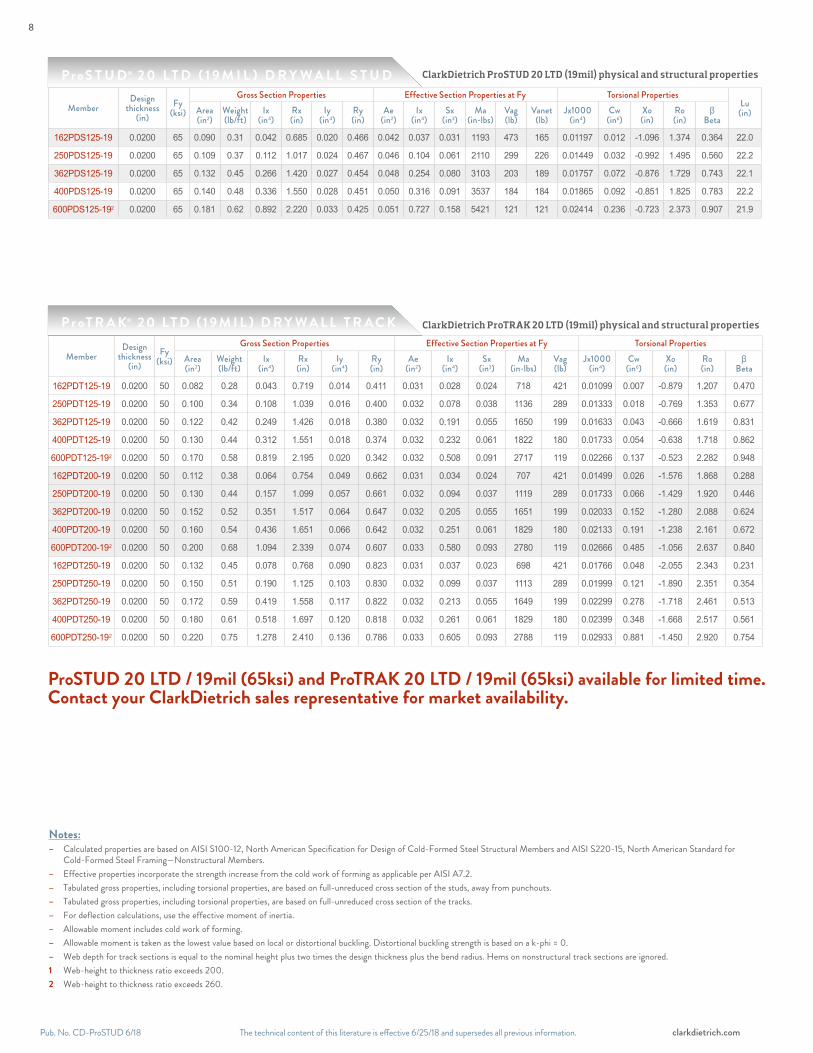
ClarkDietrich ProSTUD 20 LTD (19mil) physical and structural properties
ClarkDietrich ProTRAK 20 LTD (19mil) physical and structural properties
Notes:– Calculated properties are based on AISI S100-12, North American Specification for Design of Cold-Formed Steel Structural Members and AISI S220-15, North American Standard for
Cold-Formed Steel Framing—Nonstructural Members.– Effective properties incorporate the strength increase from the cold work of forming as applicable per AISI A7.2.– Tabulated gross properties, including torsional properties, are based on full-unreduced cross section of the studs, away from punchouts. – Tabulated gross properties, including torsional properties, are based on full-unreduced cross section of the tracks.– For deflection calculations, use the effective moment of inertia.– Allowable moment includes cold work of forming.– Allowable moment is taken as the lowest value based on local or distortional buckling. Distortional buckling strength is based on a k-phi = 0. – Web depth for track sections is equal to the nominal height plus two times the design thickness plus the bend radius. Hems on nonstructural track sections are ignored.1 Web-height to thickness ratio exceeds 200. 2 Web-height to thickness ratio exceeds 260.
MemberDesign
thickness (in)
Fy (ksi)
Gross Section Properties Effective Section Properties at Fy Torsional PropertiesArea(in2)
Weight(lb/ft)
Ix(in4)
Rx(in)
Iy(in4)
Ry(in)
Ae(in2)
Ix(in4)
Sx(in3)
Ma(in-lbs)
Vag(lb)
Jx1000(in4)
Cw(in6)
Xo(in)
Ro(in)
βBeta
162PDT125-19 0.0200 50 0.082 0.28 0.043 0.719 0.014 0.411 0.031 0.028 0.024 718 421 0.01099 0.007 -0.879 1.207 0.470
250PDT125-19 0.0200 50 0.100 0.34 0.108 1.039 0.016 0.400 0.032 0.078 0.038 1136 289 0.01333 0.018 -0.769 1.353 0.677
362PDT125-19 0.0200 50 0.122 0.42 0.249 1.426 0.018 0.380 0.032 0.191 0.055 1650 199 0.01633 0.043 -0.666 1.619 0.831
400PDT125-19 0.0200 50 0.130 0.44 0.312 1.551 0.018 0.374 0.032 0.232 0.061 1822 180 0.01733 0.054 -0.638 1.718 0.862
600PDT125-192 0.0200 50 0.170 0.58 0.819 2.195 0.020 0.342 0.032 0.508 0.091 2717 119 0.02266 0.137 -0.523 2.282 0.948
162PDT200-19 0.0200 50 0.112 0.38 0.064 0.754 0.049 0.662 0.031 0.034 0.024 707 421 0.01499 0.026 -1.576 1.868 0.288
250PDT200-19 0.0200 50 0.130 0.44 0.157 1.099 0.057 0.661 0.032 0.094 0.037 1119 289 0.01733 0.066 -1.429 1.920 0.446
362PDT200-19 0.0200 50 0.152 0.52 0.351 1.517 0.064 0.647 0.032 0.205 0.055 1651 199 0.02033 0.152 -1.280 2.088 0.624
400PDT200-19 0.0200 50 0.160 0.54 0.436 1.651 0.066 0.642 0.032 0.251 0.061 1829 180 0.02133 0.191 -1.238 2.161 0.672
600PDT200-192 0.0200 50 0.200 0.68 1.094 2.339 0.074 0.607 0.033 0.580 0.093 2780 119 0.02666 0.485 -1.056 2.637 0.840
162PDT250-19 0.0200 50 0.132 0.45 0.078 0.768 0.090 0.823 0.031 0.037 0.023 698 421 0.01766 0.048 -2.055 2.343 0.231
250PDT250-19 0.0200 50 0.150 0.51 0.190 1.125 0.103 0.830 0.032 0.099 0.037 1113 289 0.01999 0.121 -1.890 2.351 0.354
362PDT250-19 0.0200 50 0.172 0.59 0.419 1.558 0.117 0.822 0.032 0.213 0.055 1649 199 0.02299 0.278 -1.718 2.461 0.513
400PDT250-19 0.0200 50 0.180 0.61 0.518 1.697 0.120 0.818 0.032 0.261 0.061 1829 180 0.02399 0.348 -1.668 2.517 0.561
600PDT250-192 0.0200 50 0.220 0.75 1.278 2.410 0.136 0.786 0.033 0.605 0.093 2788 119 0.02933 0.881 -1.450 2.920 0.754
P r oT R A K® 2 0 LT D ( 1 9 M I L ) D R Y W A L L T R A C K
MemberDesign
thickness (in)
Fy (ksi)
Gross Section Properties Effective Section Properties at Fy Torsional PropertiesLu
(in)Area(in2)
Weight(lb/ft)
Ix(in4)
Rx(in)
Iy(in4)
Ry(in)
Ae(in2)
Ix(in4)
Sx(in3)
Ma(in-lbs)
Vag(lb)
Vanet(lb)
Jx1000(in4)
Cw(in6)
Xo(in)
Ro(in)
βBeta
162PDS125-19 0.0200 65 0.090 0.31 0.042 0.685 0.020 0.466 0.042 0.037 0.031 1193 473 165 0.01197 0.012 -1.096 1.374 0.364 22.0
250PDS125-19 0.0200 65 0.109 0.37 0.112 1.017 0.024 0.467 0.046 0.104 0.061 2110 299 226 0.01449 0.032 -0.992 1.495 0.560 22.2
362PDS125-19 0.0200 65 0.132 0.45 0.266 1.420 0.027 0.454 0.048 0.254 0.080 3103 203 189 0.01757 0.072 -0.876 1.729 0.743 22.1
400PDS125-19 0.0200 65 0.140 0.48 0.336 1.550 0.028 0.451 0.050 0.316 0.091 3537 184 184 0.01865 0.092 -0.851 1.825 0.783 22.2
600PDS125-192 0.0200 65 0.181 0.62 0.892 2.220 0.033 0.425 0.051 0.727 0.158 5421 121 121 0.02414 0.236 -0.723 2.373 0.907 21.9
ProS T U D® 2 0 L T D ( 1 9 M I L ) D R Y W A L L S T U D
ProSTUD 20 LTD / 19mil (65ksi) and ProTRAK 20 LTD / 19mil (65ksi) available for limited time.Contact your ClarkDietrich sales representative for market availability.
8

The technical content of this literature is effective 6/25/18 and supersedes all previous information. The technical content of this literature is effective 6/25/18 and supersedes all previous information. Pub. No. CD-ProSTUD 6/18clarkdietrich.com
P H Y S I C A L A N D S T R U C T U R A L P R O P E R T I E S
ClarkDietrich ProSTUD 30MIL physical and structural properties
ClarkDietrich ProTRAK 30MIL physical and structural properties
MemberDesign
thickness (in)
Fy (ksi)
Gross Section Properties Effective Section Properties at Fy Torsional PropertiesArea(in2)
Weight(lb/ft)
Ix(in4)
Rx(in)
Iy(in4)
Ry(in)
Ae(in2)
Ix(in4)
Sx(in3)
Ma(in-lbs)
Vag(lb)
J* 1000(in4)
Cw(in6)
Xo(in)
Ro(in)
β Beta
162PDT125-30 0.0312 33 0.128 0.44 0.067 0.722 0.022 0.409 0.080 0.054 0.048 951 610 0.04168 0.011 -0.872 1.204 0.475
250PDT125-30 0.0312 33 0.156 0.53 0.169 1.042 0.025 0.397 0.084 0.140 0.087 1713 832 0.05054 0.029 -0.763 1.351 0.681
362PDT125-30 0.0312 33 0.191 0.65 0.389 1.428 0.027 0.378 0.087 0.330 0.149 2938 755 0.06193 0.067 -0.661 1.619 0.833
400PDT125-30 0.0312 33 0.203 0.69 0.489 1.553 0.028 0.371 0.088 0.417 0.172 3407 683 0.06573 0.084 -0.633 1.718 0.864
600PDT125-30 0.0312 33 0.265 0.90 1.278 2.196 0.031 0.340 0.090 1.074 0.240 4737 454 0.08597 0.212 -0.519 2.282 0.948
162PDT200-30 0.0312 33 0.175 0.60 0.101 0.758 0.076 0.660 0.081 0.067 0.052 1028 610 0.05687 0.040 -1.570 1.864 0.291
250PDT200-30 0.0312 33 0.203 0.69 0.246 1.103 0.088 0.659 0.086 0.170 0.094 1862 832 0.06573 0.103 -1.423 1.917 0.449
362PDT200-30 0.0312 33 0.238 0.81 0.549 1.520 0.099 0.645 0.089 0.397 0.160 3159 755 0.07712 0.237 -1.274 2.086 0.627
400PDT200-30 0.0312 33 0.249 0.85 0.682 1.654 0.102 0.639 0.089 0.502 0.176 3480 683 0.08091 0.297 -1.232 2.160 0.674
600PDT200-30 0.0312 33 0.312 1.06 1.710 2.342 0.114 0.605 0.091 1.353 0.262 5170 454 0.10116 0.754 -1.051 2.637 0.841
162PDT250-30 0.0312 33 0.206 0.70 0.123 0.772 0.139 0.821 0.082 0.073 0.054 1059 610 0.06699 0.075 -2.048 2.338 0.233
250PDT250-30 0.0312 33 0.234 0.80 0.298 1.129 0.160 0.828 0.086 0.186 0.097 1926 832 0.07585 0.190 -1.883 2.347 0.356
362PDT250-30 0.0312 33 0.269 0.92 0.656 1.562 0.181 0.820 0.089 0.436 0.157 3097 755 0.08724 0.435 -1.712 2.458 0.515
400PDT250-30 0.0312 33 0.281 0.96 0.812 1.701 0.187 0.816 0.090 0.551 0.173 3425 683 0.09104 0.543 -1.662 2.514 0.563
600PDT250-30 0.0312 33 0.343 1.17 1.997 2.413 0.211 0.784 0.092 1.473 0.261 5162 454 0.11128 1.373 -1.444 2.919 0.755
MemberDesign
thickness (in)
Fy (ksi)
Gross Section Properties Effective Section Properties at Fy Torsional PropertiesLu
(in)Area(in2)
Weight(lb/ft)
Ix(in4)
Rx(in)
Iy(in4)
Ry(in)
Ae(in2)
Ix(in4)
Sx(in3)
Ma(in-lbs)
Vag(lb)
Vanet(lb)
J* 1000(in4)
Cw(in6)
Xo(in)
Ro(in)
βBeta
162PDS125-30 0.0312 33 0.137 0.47 0.064 0.681 0.029 0.458 0.098 0.064 0.067 1332 572 124 0.04459 0.017 -1.070 1.348 0.371 30.8
250PDS125-30 0.0312 33 0.165 0.56 0.169 1.012 0.034 0.451 0.106 0.168 0.121 2356 832 397 0.05345 0.042 -0.941 1.454 0.581 30.1
362PDS125-30 0.0312 33 0.200 0.68 0.398 1.411 0.038 0.434 0.107 0.396 0.170 3358 776 457 0.06484 0.096 -0.820 1.689 0.764 29.7
400PDS125-30 0.0312 33 0.212 0.72 0.501 1.540 0.039 0.428 0.108 0.499 0.189 3737 701 490 0.06864 0.120 -0.787 1.781 0.805 29.5
600PDS125-30 0.0312 33 0.274 0.93 1.324 2.199 0.043 0.396 0.109 1.281 0.338 6031 461 461 0.08888 0.303 -0.651 2.327 0.922 28.7
Notes:– Calculated properties are based on AISI S100-12, North American Specification for Design of Cold-Formed Steel Structural Members and AISI S220-15, North American Standard for
Cold-Formed Steel Framing—Nonstructural Members.– Effective properties incorporate the strength increase from the cold work of forming as applicable per AISI A7.2.– Tabulated gross properties, including torsional properties, are based on full-unreduced cross section of the studs, away from punchouts. – Tabulated gross properties, including torsional properties, are based on full-unreduced cross section of the tracks.– For deflection calculations, use the effective moment of inertia.– Allowable moment includes cold work of forming.– Allowable moment is taken as the lowest value based on local or distortional buckling. Distortional buckling strength is based on a k-phi = 0. – Web depth for track sections is equal to the nominal height plus two times the design thickness plus the bend radius. Hems on nonstructural track sections are ignored.1 Web-height to thickness ratio exceeds 200.2 Web-height to thickness ratio exceeds 260.
ProS T U D® 3 0 M I L D R Y W A L L S T U D ( A V A I L A B L E I N S E L E C T M A R K E T S )
ProT R A K® 30M I L D R Y WA L L T R AC K
ClarkDietrich ProSTUD 20 LTD (19mil) physical and structural properties
9

The technical content of this literature is effective 6/25/18 and supersedes all previous information.Pub. No. CD-ProSTUD 6/18 clarkdietrich.com
ClarkDietrich ProSTUD 33MIL physical and structural properties
ClarkDietrich ProTRAK 33MIL physical and structural properties
MemberDesign
thickness (in)
Fy (ksi)
Gross Section Properties Effective Section Properties at Fy Torsional PropertiesArea(in2)
Weight(lb/ft)
Ix(in4)
Rx(in)
Iy(in4)
Ry(in)
Ae(in2)
Ix(in4)
Sx(in3)
Ma(in-lbs)
Vag(lb)
J* 1000(in4)
Cw(in6)
Xo(in)
Ro(in)
β Beta
162PDT125-33 0.0346 33 0.142 0.48 0.075 0.723 0.024 0.409 0.095 0.063 0.056 1104 677 0.05683 0.012 -0.870 1.203 0.477
250PDT125-33 0.0346 33 0.173 0.59 0.188 1.043 0.027 0.397 0.102 0.160 0.100 1972 1024 0.06891 0.032 -0.762 1.351 0.682
362PDT125-33 0.0346 33 0.212 0.72 0.432 1.429 0.030 0.377 0.105 0.375 0.170 3358 1024 0.08444 0.074 -0.659 1.618 0.834
400PDT125-33 0.0346 33 0.225 0.77 0.542 1.554 0.031 0.371 0.106 0.473 0.197 3887 931 0.08962 0.093 -0.632 1.718 0.865
600PDT125-33 0.0346 33 0.294 1.00 1.418 2.197 0.034 0.339 0.109 1.237 0.287 5681 619 0.11723 0.234 -0.517 2.282 0.949
162PDT200-33 0.0346 33 0.194 0.66 0.112 0.759 0.085 0.660 0.097 0.077 0.061 1198 677 0.07754 0.045 -1.568 1.862 0.292
250PDT200-33 0.0346 33 0.225 0.77 0.274 1.104 0.097 0.658 0.104 0.196 0.109 2150 1024 0.08962 0.114 -1.421 1.916 0.450
362PDT200-33 0.0346 33 0.264 0.90 0.610 1.521 0.110 0.645 0.107 0.452 0.186 3669 1024 0.10515 0.263 -1.272 2.085 0.628
400PDT200-33 0.0346 33 0.276 0.94 0.758 1.655 0.113 0.639 0.108 0.567 0.215 4246 931 0.11033 0.329 -1.230 2.159 0.675
600PDT200-33 0.0346 33 0.346 1.18 1.897 2.342 0.126 0.604 0.111 1.520 0.322 6355 619 0.13795 0.835 -1.050 2.637 0.842
162PDT250-33 0.0346 33 0.229 0.78 0.137 0.774 0.154 0.821 0.098 0.085 0.063 1235 677 0.09135 0.083 -2.046 2.336 0.233
250PDT250-33 0.0346 33 0.259 0.88 0.331 1.130 0.177 0.827 0.104 0.214 0.113 2225 1024 0.10343 0.211 -1.881 2.346 0.357
362PDT250-33 0.0346 33 0.298 1.01 0.728 1.563 0.200 0.820 0.108 0.493 0.193 3808 1024 0.11896 0.482 -1.710 2.457 0.516
400PDT250-33 0.0346 33 0.311 1.06 0.901 1.702 0.207 0.815 0.109 0.622 0.214 4221 931 0.12414 0.602 -1.660 2.514 0.564
600PDT250-33 0.0346 33 0.380 1.29 2.216 2.414 0.233 0.783 0.111 1.657 0.320 6327 619 0.15175 1.522 -1.443 2.919 0.756
MemberDesign
thickness (in)
Fy (ksi)
Gross Section Properties Effective Section Properties at Fy Torsional PropertiesLu
(in)Area(in2)
Weight(lb/ft)
Ix(in4)
Rx(in)
Iy(in4)
Ry(in)
Ae(in2)
Ix(in4)
Sx(in3)
Ma(in-lbs)
Vag(lb)
Vanet(lb)
J* 1000(in4)
Cw(in6)
Xo(in)
Ro(in)
βBeta
162PDS125-33 0.0346 33 0.152 0.52 0.070 0.679 0.032 0.456 0.114 0.070 0.078 1541 632 123 0.06059 0.019 -1.065 1.344 0.371 30.8
250PDS125-33 0.0346 33 0.182 0.62 0.186 1.010 0.037 0.449 0.125 0.186 0.138 2697 1007 431 0.07267 0.046 -0.937 1.449 0.582 30.1
362PDS125-33 0.0346 33 0.221 0.75 0.439 1.409 0.041 0.433 0.127 0.439 0.200 3943 1024 541 0.08820 0.106 -0.816 1.685 0.766 29.6
400PDS125-33 0.0346 33 0.234 0.80 0.553 1.538 0.043 0.426 0.128 0.553 0.222 4394 957 602 0.09338 0.132 -0.783 1.777 0.806 29.5
600PDS125-33 0.0346 33 0.303 1.03 1.463 2.196 0.047 0.394 0.130 1.428 0.399 7021 630 630 0.12100 0.332 -0.647 2.323 0.922 28.6
Notes:– Calculated properties are based on AISI S100-12, North American Specification for Design of Cold-Formed Steel Structural Members and AISI S220-15, North American Standard for
Cold-Formed Steel Framing—Nonstructural Members.– Effective properties incorporate the strength increase from the cold work of forming as applicable per AISI A7.2.– Tabulated gross properties, including torsional properties, are based on full-unreduced cross section of the studs, away from punchouts. – Tabulated gross properties, including torsional properties, are based on full-unreduced cross section of the tracks.– For deflection calculations, use the effective moment of inertia.– Allowable moment includes cold work of forming.– Allowable moment is taken as the lowest value based on local or distortional buckling. Distortional buckling strength is based on a k-phi = 0. – Web depth for track sections is equal to the nominal height plus two times the design thickness plus the bend radius. Hems on nonstructural track sections are ignored.1 Web-height to thickness ratio exceeds 200.2 Web-height to thickness ratio exceeds 260.
ProS T U D® 3 3 M I L D R Y W A L L S T U D ( A V A I L A B L E I N S E L E C T M A R K E T S )
ProT R A K® 33 M I L D R Y WA L L T R AC K
P H Y S I C A L A N D S T R U C T U R A L P R O P E R T I E S10

The technical content of this literature is effective 6/25/18 and supersedes all previous information. The technical content of this literature is effective 6/25/18 and supersedes all previous information. Pub. No. CD-ProSTUD 6/18clarkdietrich.com
ClarkDietrich ProSTUD 33MIL physical and structural properties
Notes:– Allowable screw connection capacities are based on Section E4 of the AISI S100-12 Specification.– When connecting materials of different steel thicknesses or tensile strengths, use the lowest values. Tabulated values assume two sheets of equal thickness are connected.– Screw shear and tension capacities were developed using published screw manufacturer data and evaluation reports available at the time of publication.– Screw capacities are based on Allowable Strength Design (ASD) and include a safety factor of 3.0.– When multiple fasteners are used, screws are assumed to have a center-to-center spacing of at least three times the nominal diameter (d).– Screws are assumed to have a center-of-screw to edge-of-steel dimension of at least 1-1/2 times the nominal diameter (d) of the screw.– Tension capacity is based on the lesser of pullout capacity in sheet closest to screw tip, or pullover capacity for sheet closest to screw head (using head diameter).– Screw capacities are governed by a conservative estimate of screw capacity, not by sheet steel failure.– For higher screw capacities, especially for screw strength, use specific screws from specific manufacturer. See manufacturer’s data for specific allowable values and
installation instructions.
A L L O W A B L E S C R E W D E S I G N V A L U E S ( L B S )
2-Sided PulloverPullout / Shear
Pul
lout
Shear
C O N N E C T I O N S
Member designation
Thickness (mils)
Design thickness
(in)Yield(ksi) Ultimate
#6 Screw (0.138" Dia., 5/16" Head) #8 Screw (0.164" Dia., 5/16" Head) #10 Screw (0.190" Dia., 0.34" Head)Shear,
lbs 1-Side 2-Side Pullout, lbs
Shear, lbs 1-Side 2-Side Pullout,
lbsShear,
lbs 1-Side 2-Side Pullout, lbs
PDS125-15 15 0.0158 50 50 52 62 123 31 56 62 123 37 61 67 134 43PDS125-18 18 0.0190 70 70 95 104 208 52 104 104 208 62 112 113 226 72PDS125-19 19 0.0200 65 65 96 102 203 51 104 102 203 60 112 111 221 70PDS125-30 30 0.0312 33 33 95 80 161 40 103 80 161 48 111 88 175 55PDS125-33 33 0.0346 33 45 151 122 243 61 164 122 243 72 177 132 265 84
11
12"
max
.
The technical content of this literature is effective 6/25/18 and supersedes all previous information.Pub. No. CD-ProSTUD 6/18 clarkdietrich.com
L I M I T I N G H E I G H T S O V E R V I E W
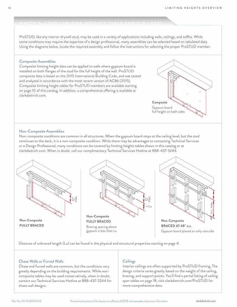
ProSTUD, like any interior drywall stud, may be used in a variety of applications including walls, ceilings, and soffits. While some conditions may require the expertise of a design professional, many assemblies can be selected based on tabulated data. Using the diagrams below, locate the required assembly and follow the instructions for selecting the proper ProSTUD member.
Composite AssembliesComposite limiting height data can be applied to walls where gypsum board is installed on both flanges of the stud for the full height of the wall. ProSTUD composite data is based on the 2015 International Building Code, and was tested and analyzed in accordance with the most recent version of AC86 (2015). Composite limiting height tables for ProSTUD members are available starting on page 10 of this catalog. In addition, a comprehensive offering is available at clarkdietrich.com.
Chase Walls or Furred WallsChase and furred walls are common, but the conditions vary greatly depending on the building requirements. While non-composite tables may be used conservatively, when in doubt, contact our Technical Services Hotline at 888-437-3244 for chase wall designs.
CeilingsInterior ceilings are often supported by ProSTUD framing. The design criteria varies greatly based on the weight of the ceiling, bracing, and support points. You'll find a partial listing of ceiling span tables on page 18; visit clarkdietrich.com/ProSTUD for more comprehensive data.
Non-Composite AssembliesNon-composite conditions are common in all structures. When the gypsum board stops at the ceiling level, but the stud continues to the deck, it is a non-composite condition. While there may be advantages to contacting Technical Services or a Design Professional, many conditions can be covered by limiting heights tables shown in this catalog or at clarkdietrich.com. When in doubt, call our complimentary Technical Services Hotline at 888-437-3244.
Non-CompositeFULLY BRACED
Distance of unbraced length (Lu) can be found in the physical and structural properties starting on page 4.
< Lu48
" o.c.
max
.
CompositeGypsum board full height on both sides
Non-CompositeFULLY BRACEDBracing spacing above gypsum is less than Lu
Non-CompositeBRACED AT 48" o.c.Gypsum board placed on only one side
W H I C H ProS T U D® L I M I T I N G H E I G H T S T A B L E S H O U L D I U S E ?
12"
m
ax.
12"
max
.
12
The technical content of this literature is effective 6/25/18 and supersedes all previous information. The technical content of this literature is effective 6/25/18 and supersedes all previous information. Pub. No. CD-ProSTUD 6/18clarkdietrich.com
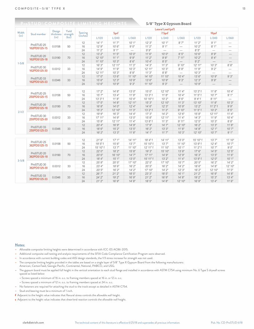
C O M P O S I T E — 5 / 8 " T Y P E X
ProS T U D ® C O M P O S I T E L I M I T I N G H E I G H T S
Notes:– Allowable composite limiting heights were determined in accordance with ICC-ES AC86-2015. – Additional composite wall testing and analysis requirements of the SFIA Code Compliance Certification Program were observed.– In accordance with current building codes and AISI design standards, the 1/3 stress increase for strength was not used.– The composite limiting heights provided in the tables are based on a single layer of 5/8" Type X Gypsum Board from the following manufacturers:
American, CertainTeed, Georgia Pacific, Continental, National, PABCO, and USG.– The gypsum board must be applied full height in the vertical orientation to each stud flange and installed in accordance with ASTM C754 using minimum No. 6 Type S drywall screws
spaced as listed below: – Screws spaced a minimum of 16 in. o.c. to framing members spaced at 16 in. or 12 in. o.c. – Screws spaced a minimum of 12 in. o.c. to framing members spaced at 24 in. o.c.– No fasteners are required for attaching the stud to the track except as detailed in ASTM C754.– Stud end bearing must be a minimum of 1 inch.f Adjacent to the height value indicates that flexural stress controls the allowable wall height.s Adjacent to the height value indicates that shear/end reaction controls the allowable wall height.
Width(in) Stud member
Design thickness
(in)
Yield strength
(ksi)Spacing(inches)
Lateral Load (psf)5psf 7.5psf 10psf
L/120 L/240 L/360 L/120 L/240 L/360 L/120 L/240 L/360
1-5/8
ProSTUD 25162PDS125-15 0.0158 50
12 14' 1" 11' 7" 10' 1" 12' 3" 10' 1" 8' 7" 11' 2" 9' 1" —16 12' 9" 10' 6" 9' 0" 11' 2" 9' 1" — 10' 2" 8' 1" —24 11' 2" 9' 1" — 9' 9" — — 8' 5" — —
ProSTUD 20162PDS125-18 0.0190 70
12 13' 2'' 11' 5'' 10' 0'' 11' 6'' 10' 0'' 8' 5'' 10' 6'' 8' 9'' —16 12' 10'' 11' 1'' 9' 9'' 11' 2'' 9' 8'' 7' 11'' 10' 2'' 8' 4'' —24 11' 10'' 10' 3'' 8' 6'' 10' 4'' 8' 5'' — 9' 2'' — —
ProSTUD 30 162PDS125-30 0.0312 33
12 16' 3" 12' 11" 11' 3" 14' 3" 11' 3" 9' 10" 12' 11" 10' 3" 8' 8"16 14' 9" 11' 9" 10' 3" 12' 11" 10' 3" 8' 8" 11' 9" 9' 2" —24 12' 11" 10' 3" 8' 8" 11' 3" 8' 8" — 10' 3" — —
ProSTUD 33 162PDS125-33 0.0346 33
12 17' 0" 13' 6" 11' 10" 14' 10" 11' 10" 10' 4" 13' 6" 10' 9" 9' 3"16 15' 6" 12' 3" 10' 9" 13' 6" 10' 9" 9' 3" 12' 3" 9' 9" —24 13' 6" 10' 9" 9' 3" 11' 10" 9' 3" — 10' 9" — —
2-1/2
ProSTUD 25250PDS125-15 0.0158 50
12 17' 2" 14' 8" 13' 0" 15' 0" 12' 10" 11' 4" 13' 3" f 11' 8" 10' 4"16 15' 7" 13' 4" 11' 9" 13' 3" f 11' 8" 10' 4" 11' 5" f 10' 7" 9' 1"24 13' 3" f 11' 8" 10' 4" 10' 10" f 10' 2" 8' 6" 9' 4" f 8' 11" —
ProSTUD 20250PDS125-18 0.0190 70
12 17' 5'' 14' 8'' 12' 11'' 15' 3'' 12' 10'' 11' 3'' 13' 10'' 11' 8'' 10' 3''16 16' 8'' 14' 0'' 12' 4'' 14' 6'' 12' 3'' 10' 9'' 13' 2'' 11' 2'' f 9' 9''24 15' 2'' 12' 10'' 11' 3'' 13' 2'' f 11' 2'' 9' 10'' 11' 5'' f 10' 2'' 8' 5''
ProSTUD 30 250PDS125-30 0.0312 33
12 19' 9" 16' 3" 14' 4" 17' 3" 14' 2" 12' 6" 15' 8" 12' 11" 11' 4"16 17' 11" 14' 9" 13' 0" 15' 8" 12' 11" 11' 4" 14' 3" 11' 9" 10' 4"24 15' 8" 12' 11" 11' 4" 13' 8" f 11' 3" 9' 11" 12' 5" 10' 3" 8' 8"
ProSTUD 33 250PDS125-33 0.0346 33
12 20' 4" 16' 9" 14' 9" 17' 9" 14' 7" 12' 10" 16' 2" 13' 3" 11' 8"16 18' 6" 15' 2" 13' 5" 16' 2" 13' 3" 11' 8" 14' 8" 12' 1" 10' 7"24 16' 2" 13' 3" 11' 8" 14' 1" 11' 7" 10' 3" 12' 10" 10' 7" 9' 1"
3-5/8
ProSTUD 25362PDS125-15 0.0158 50
12 21' 6" 17' 1" 14' 11" 18' 4" f 14' 11" 13' 0" 15' 10" f 13' 7" 11' 10"16 19' 5" f 15' 6" 13' 7" 15' 10" f 13' 7" 11' 10" 13' 9" f 12' 4" 10' 7"24 15' 10" f 13' 7" 11' 10" 12' 11" f 11' 10" 10' 1" 11' 2" f 10' 7" 9' 0"
ProSTUD 20362PDS125-18 0.0190 70
12 22' 0'' 18' 2'' 15' 8'' 19' 3'' 15' 10'' 13' 8'' 17' 6'' 14' 5'' 12' 5''16 20' 6'' 16' 10'' 14' 7'' 17' 11'' 14' 9'' 12' 9'' 16' 3'' 13' 5'' 11' 6''24 18' 4'' 15' 1'' 13' 0'' 15' 11'' f 13' 2'' 11' 4'' 13' 9'' f 12' 0'' 10' 1''
ProSTUD 30 362PDS125-30 0.0312 33
12 25' 8" 20' 5" 17' 10" 22' 5" 17' 10" 15' 7" 20' 5" 16' 2" 14' 2"16 23' 4" 18' 6" 16' 2" 20' 5" 16' 2" 14' 2" 18' 6" 14' 8" 12' 10"24 20' 5" 16' 2" 14' 2" 17' 10" 14' 2" 12' 3" 16' 2" 12' 10" 11' 0"
ProSTUD 33 362PDS125-33 0.0346 33
12 26' 7" 21' 2" 18' 5" 23' 3" 18' 5" 16' 1" 21' 2" 16' 9" 14' 8"16 24' 2" 19' 2" 16' 9" 21' 2" 16' 9" 14' 8" 19' 2" 15' 3" 13' 4"24 21' 2" 16' 9" 14' 8" 18' 5" 14' 8" 12' 10" 16' 9" 13' 4" 11' 6"
5/8" Type X Gypsum Board
13

The technical content of this literature is effective 6/25/18 and supersedes all previous information.Pub. No. CD-ProSTUD 6/18 clarkdietrich.com
Notes:– Allowable composite limiting heights were determined in accordance with ICC-ES AC86-2015. – Additional composite wall testing and analysis requirements of the SFIA Code Compliance Certification Program were observed.– In accordance with current building codes and AISI design standards, the 1/3 stress increase for strength was not used.– The composite limiting heights provided in the tables are based on a single layer of 5/8" Type X Gypsum Board from the following manufacturers:
American, CertainTeed, Georgia Pacific, Continental, National, PABCO, and USG.– The gypsum board must be applied full height in the vertical orientation to each stud flange and installed in accordance with ASTM C754 using minimum No. 6 Type S drywall screws
spaced as listed below: – Screws spaced a minimum of 16 in. o.c. to framing members spaced at 16 in. or 12 in. o.c. – Screws spaced a minimum of 12 in. o.c. to framing members spaced at 24 in. o.c.– No fasteners are required for attaching the stud to the track except as detailed in ASTM C754.– Stud end bearing must be a minimum of 1 inch.f Adjacent to the height value indicates that flexural stress controls the allowable wall height.s Adjacent to the height value indicates that shear/end reaction controls the allowable wall height.
5/8" Type X Gypsum BoardProS T U D ® C O M P O S I T E L I M I T I N G H E I G H T S
Width(in) Stud member
Design thickness
(in)
Yield strength
(ksi)Spacing(inches)
Lateral Load (psf)5psf 7.5psf 10psf
L/120 L/240 L/360 L/120 L/240 L/360 L/120 L/240 L/360
4
ProSTUD 25400PDS125-15 0.0158 50
12 22' 8" 18' 0" 15' 9" 19' 1" f 15' 9" 13' 9" 16' 6" f 14' 4" 12' 6"16 20' 3" f 16' 4" 14' 4" 16' 6" f 14' 4" 12' 6" 14' 4" f 13' 0" 11' 3"24 16' 6" f 14' 4" 12' 6" 13' 6" f 12' 6" 10' 8" 11' 8" f 11' 3" 9' 6"
ProSTUD 20400PDS125-18 0.0190 70
12 22' 9'' 18' 8'' 16' 4'' 19' 11'' 16' 4'' 14' 3'' 18' 1'' 14' 10'' 13' 0''16 21' 4'' 17' 7'' 15' 4'' 18' 8'' 15' 4'' 13' 5'' 16' 11'' 13' 11'' 12' 2''24 19' 3'' 15' 10'' 13' 10'' 16' 7'' f 13' 10'' 12' 1'' 14' 4'' f 12' 6'' 10' 9''
ProSTUD 30 400PDS125-30 0.0312 33
12 27' 5" 21' 9" 19' 0" 24' 0" 19' 0" 16' 8" 21' 9" 17' 4" 15' 1"16 24' 11" 19' 10" 17' 4" 21' 9" 17' 4" 15' 1" 19' 10" 15' 9" 13' 9"24 21' 9" 17' 4" 15' 1" 19' 0" 15' 1" 13' 2" 17' 4" 13' 9" 11' 10"
ProSTUD 33 400PDS125-33 0.0346 33
12 27' 10" 22' 9" 20' 1" 24' 3" 19' 11" 17' 7" 22' 1" 18' 1" 15' 11"16 25' 3" 20' 8" 18' 3" 22' 1" 18' 1" 15' 11" 20' 1" 16' 5" 14' 6"24 22' 1" 18' 1" 15' 11" 19' 3" 15' 10" 13' 11" 17' 6" 14' 4" 12' 8"
6
ProSTUD 25600PDS125-15 0.0158 50
12 27' 10" f 24' 2" 21' 5" 22' 9" f 21' 1" 18' 8" 19' 8" f 19' 2" 17' 0"16 24' 1" f 21' 11" 19' 5" 19' 8" f 19' 2" 17' 0" 17' 1" f 17' 1" f 15' 5"24 19' 8" f 19' 2" 17' 0" 16' 1" f 16' 1" f 14' 9" 13' 11" f 13' 11" f 13' 4"
ProSTUD 20600PDS125-18 0.0190 70
12 32' 1'' 25' 6'' 22' 3'' 28' 1'' 22' 3'' 19' 5'' 24' 4'' f 20' 3'' 17' 8''16 29' 10'' 23' 8'' 20' 8'' 24' 10'' f 20' 8'' 18' 1'' 21' 6'' f 18' 9'' 16' 5''24 25' 5'' f 21' 1'' 18' 5'' 20' 9'' f 18' 5'' 16' 1'' 18' 0'' f 16' 9'' 14' 6''
ProSTUD 30 600PDS125-30 0.0312 33
12 36' 7" 29' 1" 25' 5" 32' 0" 25' 5" 22' 2" 29' 1" 23' 1" 20' 2"16 33' 3" 26' 5" 23' 1" 29' 1" 23' 1" 20' 2" 26' 5" 20' 11" 18' 4"24 29' 1" 23' 1" 20' 2" 25' 5" 20' 2" 17' 7" 22' 6" f 18' 4" —
ProSTUD 33 600PDS125-33 0.0346 33
12 36' 8" 30' 1" 26' 6" 32' 0" 26' 3" 23' 2" 29' 1" 23' 10" 21' 0"16 33' 3" 27' 4" 24' 1" 29' 1" 23' 10" 21' 0" 26' 5" 21' 8" 19' 1"24 29' 1" 23' 10" 21' 0" 25' 5" 20' 10" 18' 4" 23' 1" 18' 11" —
C O M P O S I T E — 5 / 8 " T Y P E X14

The technical content of this literature is effective 6/25/18 and supersedes all previous information. The technical content of this literature is effective 6/25/18 and supersedes all previous information. Pub. No. CD-ProSTUD 6/18clarkdietrich.com
N O N - C O M P O S I T E F U L L Y B R A C E D
ClarkDietrich ProSTUD Non-Composite Limiting Heights—FULLY BRACEDProS T U D ® N O N - C O M P O S I T E L I M I T I N G H E I G H T S
Notes:– Heights are based on AISI S100-12, North American Specification and AISI S220-15, North American Standard for Cold-Formed Steel Framing—
Nonstructural Members, using steel properties alone.– Above listed Non-Composite Limiting Heights are applicable when the unbraced length is less than or equal to Lu.– Heights are limited by moment, deflection, shear, and web crippling (assuming 1" end reaction bearing). .Web stiffeners are required at bearing points ٭
Depth (in) Stud member
Design thickness
(in)
Yield strength
(ksi)
Spacing o.c. (in)
Lateral Load (psf)5psf 7.5psf 10psf
L/120 L/240 L/360 L/120 L/240 L/360 L/120 L/240 L/360
1-5/8
ProSTUD 25162PDS125-15
0.0158 50 12 9' 2" 7' 4" 6' 4" 8' 0" 6' 4" 5' 7" 6' 11" 5' 9" 5' 1" 0.0158 50 16 8' 4" 6' 8" 5' 9" 6' 11" 5' 9" 5' 1" 6' 0" 5' 3" 4' 7" 0.0158 50 24 6' 11" 5' 9" 5' 1" 5' 8" 5' 1" 4' 5" 4' 11" 4' 7" 4' 0"
ProSTUD 20162PDS125-18
0.0190 70 12 9' 9" 7' 9" 6' 9" 8' 6" 6' 9" 5' 11" 7' 9" 6' 2" 5' 4" 0.0190 70 16 8' 10" 7' 0" 6' 2" 7' 9" 6' 2" 5' 4" 7' 0" 5' 7" 4' 10" 0.0190 70 24 7' 9" 6' 2" 5' 4" 6' 9" 5' 4" 4' 8" 6' 2" 4' 10" 4' 3"
ProSTUD 30MIL162PDS125-30
0.0312 33 12 11' 10" 9' 5" 8' 3" 10' 4" 8' 3" 7' 2" 9' 5" 7' 6" 6' 6" 0.0312 33 16 10' 9" 8' 7" 7' 6" 9' 5" 7' 6" 6' 6" 8' 2" 6' 9" 5' 11" 0.0312 33 24 9' 5" 7' 6" 6' 6" 7' 8" 6' 6" 5' 8" 6' 8" 5' 11" 5' 2"
ProSTUD 33MIL162PDS125-33
0.0346 33 12 12' 3" 9' 9" 8' 6" 10' 8" 8' 6" 7' 5" 9' 9" 7' 9" 6' 9" 0.0346 33 16 11' 2" 8' 10" 7' 9" 9' 9" 7' 9" 6' 9" 8' 9" 7' 0" 6' 1" 0.0346 33 24 9' 9" 7' 9" 6' 9" 8' 3" 6' 9" 5' 11" 7' 2" 6' 1" 5' 4"
2-1/2
ProSTUD 25250PDS125-15
0.0158 50 12 12' 8" 10' 2" 8' 11" 10' 4" 8' 11" 7' 9" 8' 11" 8' 1" 7' 1" 0.0158 50 16 10' 11" 9' 3" 8' 1" 8' 11" 8' 1" 7' 1" 7' 9" 7' 4" 6' 5" 0.0158 50 24 8' 11" 8' 1" 7' 1" 7' 4" 7' 1" 6' 2" 6' 4" 6' 4" 5' 7"
ProSTUD 20250PDS125-18
0.0190 70 12 13' 9" 10' 11" 9' 6" 12' 0" 9' 6" 8' 4" 10' 11" 8' 8" 7' 7" 0.0190 70 16 12' 6" 9' 11" 8' 8" 10' 11" 8' 8" 7' 7" 9' 11" 7' 10" 6' 10" 0.0190 70 24 10' 11" 8' 8" 7' 7" 9' 6" 7' 7" 6' 7" 8' 4" 6' 10" 6' 0"
ProSTUD 30MIL250PDS125-30
0.0312 33 12 16' 5" 13' 0" 11' 4" 14' 4" 11' 4" 9' 11" 12' 6" 10' 4" 9' 0" 0.0312 33 16 14' 11" 11' 10" 10' 4" 12' 6" 10' 4" 9' 0" 10' 10" 9' 5" 8' 2" 0.0312 33 24 12' 6" 10' 4" 9' 0" 10' 3" 9' 0" 7' 11" 8' 10" 8' 2" 7' 2"
ProSTUD 33MIL250PDS125-33
0.0346 33 12 16' 11" 13' 5" 11' 9" 14' 10" 11' 9" 10' 3" 13' 5" 10' 8" 9' 4" 0.0346 33 16 15' 5" 12' 3" 10' 8" 13' 5" 10' 8" 9' 4" 11' 7" 9' 8" 8' 6" 0.0346 33 24 13' 5" 10' 8" 9' 4" 10' 11" 9' 4" 8' 2" 9' 6" 8' 6" 7' 5"
3-5/8
ProSTUD 25٭362PDS125-15
0.0158 50 12 15' 0" 13' 7" 11' 10" 12' 3" 11' 10" 10' 4" 10' 7" 10' 7" 9' 5" 0.0158 50 16 13' 0" 12' 4" 10' 9" 10' 7" 10' 7" 9' 5" 9' 2" 9' 2" 8' 6" 0.0158 50 24 10' 7" 10' 7" 9' 5" 8' 8" 8' 8" 8' 3" 7' 6" 7' 6" 7' 5"
ProSTUD 20362PDS125-18
0.0190 70 12 18' 4" 14' 6" 12' 8" 16' 0" 12' 8" 11' 1" 14' 5" 11' 6" 10' 1" 0.0190 70 16 16' 8" 13' 2" 11' 6" 14' 5" 11' 6" 10' 1" 12' 5" 10' 6" 9' 2" 0.0190 70 24 14' 5" 11' 6" 10' 1" 11' 9" 10' 1" 8' 10" 10' 2" 9' 2" 8' 0"
ProSTUD 30MIL362PDS125-30
0.0312 33 12 21' 2" 17' 4" 15' 2" 17' 3" 15' 2" 13' 3" 15' 0" 13' 9" 12' 0" 0.0312 33 16 18' 4" 15' 9" 13' 9" 15' 0" 13' 9" 12' 0" 12' 11" 12' 6" 10' 11" 0.0312 33 24 15' 0" 13' 9" 12' 0" 12' 3" 12' 0" 10' 6" 10' 7" 10' 7" 9' 6"
ProSTUD 33MIL362PDS125-33
0.0346 33 12 22' 7" 17' 11" 15' 8" 18' 9" 15' 8" 13' 8" 16' 3" 14' 3" 12' 5" 0.0346 33 16 19' 10" 16' 3" 14' 3" 16' 3" 14' 3" 12' 5" 14' 0" 12' 11" 11' 3" 0.0346 33 24 16' 3" 14' 3" 12' 5" 13' 3" 12' 5" 10' 10" 11' 6" 11' 3" 9' 10"
4
ProSTUD 25٭400PDS125-15
0.0158 50 12 15' 9" 14' 6" 12' 8" 12' 11" 12' 8" 11' 1" 11' 2" 11' 2" 10' 1" 0.0158 50 16 13' 8" 13' 2" 11' 6" 11' 2" 11' 2" 10' 1" 9' 8" 9' 8" 9' 2" 0.0158 50 24 11' 2" 11' 2" 10' 1" 9' 1" 9' 1" 8' 9" 7' 11" 7' 11" 7' 11"
ProSTUD 20٭400PDS125-18
0.0190 70 12 19' 7" 15' 6" 13' 7" 17' 1" 13' 7" 11' 10" 15' 4" 12' 4" 10' 9" 0.0190 70 16 17' 9" 14' 1" 12' 4" 15' 4" 12' 4" 10' 9" 13' 3" 11' 2" 9' 9" 0.0190 70 24 15' 4" 12' 4" 10' 9" 12' 6" 10' 9" 9' 5" 10' 10" 9' 9" 8' 7"
ProSTUD 30MIL400PDS125-30
0.0312 33 12 22' 4" 18' 8" 16' 4" 18' 3" 16' 4" 14' 3" 15' 9" 14' 10" 13' 0" 0.0312 33 16 19' 4" 17' 0" 14' 10" 15' 9" 14' 10" 13' 0" 13' 8" 13' 6" 11' 9" 0.0312 33 24 15' 9" 14' 10" 13' 0" 12' 11" 12' 11" 11' 4" 11' 2" 11' 2" 10' 3"
ProSTUD 33MIL400PDS125-33
0.0346 33 12 24' 2" 19' 4" 16' 11" 19' 9" 16' 11" 14' 9" 17' 1" 15' 4" 13' 5" 0.0346 33 16 21' 0" 17' 7" 15' 4" 17' 1" 15' 4" 13' 5" 14' 10" 13' 11" 12' 2" 0.0346 33 24 17' 1" 15' 4" 13' 5" 14' 0" 13' 5" 11' 9" 12' 1" 12' 1" 10' 8"
6
ProSTUD 25٭600PDS125-15
0.0158 50 12 19' 3" 19' 2" 16' 9" 15' 9" 15' 9" 14' 8" 11' 11" 11' 11" 11' 11" 0.0158 50 16 16' 8" 16' 8" 15' 3" 11' 11" 11' 11" 11' 11" 8' 11" 8' 11" 8' 11" 0.0158 50 24 11' 11" 11' 11" 11' 11" 7' 11" 7' 11" 7' 11" 6' 0" 6' 0" 6' 0"
ProSTUD 20٭600PDS125-18
0.0190 70 12 26' 0" 20' 8" 18' 0" 21' 11" 18' 0" 15' 9" 19' 0" 16' 4" 14' 4" 0.0190 70 16 23' 3" 18' 9" 16' 4" 19' 0" 16' 4" 14' 4" 15' 7" 14' 11" 13' 0" 0.0190 70 24 19' 0" 16' 4" 14' 4" 13' 10" 13' 10" 12' 6" 10' 5" 10' 5" 10' 5"
ProSTUD 30MIL600PDS125-30
0.0312 33 12 28' 4" 25' 7" 22' 4" 23' 2" 22' 4" 19' 7" 20' 1" 20' 1" 17' 9" 0.0312 33 16 24' 7" 23' 3" 20' 4" 20' 1" 20' 1" 17' 9" 17' 4" 17' 4" 16' 2" 0.0312 33 24 20' 1" 20' 1" 17' 9" 16' 4" 16' 4" 15' 6" 14' 2" 14' 2" 14' 1"
ProSTUD 33MIL600PDS125-33
0.0346 33 12 30' 7" 26' 7" 23' 2" 25' 0" 23' 2" 20' 3" 21' 8" 21' 1" 18' 5" 0.0346 33 16 26' 6" 24' 1" 21' 1" 21' 8" 21' 1" 18' 5" 18' 9" 18' 9" 16' 9" 0.0346 33 24 21' 8" 21' 1" 18' 5" 17' 8" 17' 8" 16' 1" 15' 4" 15' 4" 14' 7"
15

The technical content of this literature is effective 6/25/18 and supersedes all previous information.Pub. No. CD-ProSTUD 6/18 clarkdietrich.com
Notes:– Heights are based on AISI S100-12, North American Specification and AISI S220-15, North American Standard for Cold-Formed Steel Framing—
Nonstructural Members, using steel properties alone.– Above listed Non-Composite Limiting Heights are applicable when the unbraced length is less than or equal to Lu.– Heights are limited by moment, deflection, shear, and web crippling (assuming 1" end reaction bearing). .Web stiffeners are required at bearing points ٭
N O N - C O M P O S I T E B R A C E D A T 4 8" O . C .
ClarkDietrich ProSTUD Non-Composite Limiting Heights—BRACED AT 48" o.c.ProS T U D ® N O N - C O M P O S I T E L I M I T I N G H E I G H T S
Depth (in) Stud member
Design thickness
(in)
Yield strength
(ksi)
Spacing o.c. (in)
Lateral Load (psf)5psf 7.5psf 10psf
L/120 L/240 L/360 L/120 L/240 L/360 L/120 L/240 L/360
1-5/8
ProSTUD 25162PDS125-15
0.0158 50 12 8' 1" 7' 4" 6' 4" 6' 7" 6' 4" 5' 7" 5' 9" 5' 9" 5' 1" 0.0158 50 16 7' 0" 6' 8" 5' 9" 5' 9" 5' 9" 5' 1" 4' 11" 4' 11" 4' 7" 0.0158 50 24 5' 9" 5' 9" 5' 1" 4' 8" 4' 8" 4' 5" 4' 0" 4' 0" 4' 0"
ProSTUD 20162PDS125-18
0.0190 70 12 9' 6" 7' 9" 6' 9" 7' 9" 6' 9" 5' 11" 6' 9" 6' 2" 5' 4" 0.0190 70 16 8' 3" 7' 0" 6' 2" 6' 9" 6' 2" 5' 4" 5' 10" 5' 7" 4' 10" 0.0190 70 24 6' 9" 6' 2" 5' 4" 5' 6" 5' 4" 4' 8" 4' 9" 4' 9" 4' 3"
ProSTUD 30MIL162PDS125-30
0.0312 33 12 11' 10" 9' 5" 8' 3" 10' 3" 8' 3" 7' 2" 8' 11" 7' 6" 6' 6" 0.0312 33 16 10' 9" 8' 7" 7' 6" 8' 11" 7' 6" 6' 6" 7' 8" 6' 9" 5' 11" 0.0312 33 24 8' 11" 7' 6" 6' 6" 7' 3" 6' 6" 5' 8" 6' 3" 5' 11" 5' 2"
ProSTUD 33MIL162PDS125-33
0.0346 33 12 12' 3" 9' 9" 8' 6" 10' 8" 8' 6" 7' 5" 9' 5" 7' 9" 6' 9" 0.0346 33 16 11' 2" 8' 10" 7' 9" 9' 5" 7' 9" 6' 9" 8' 2" 7' 0" 6' 1" 0.0346 33 24 9' 5" 7' 9" 6' 9" 7' 8" 6' 9" 5' 11" 6' 8" 6' 1" 5' 4"
2-1/2
ProSTUD 25250PDS125-15
0.0158 50 12 10' 5" 10' 2" 8' 11" 8' 6" 8' 6" 7' 9" 7' 4" 7' 4" 7' 1" 0.0158 50 16 9' 0" 9' 0" 8' 1" 7' 4" 7' 4" 7' 1" 6' 5" 6' 5" 6' 5" 0.0158 50 24 7' 4" 7' 4" 7' 1" 6' 0" 6' 0" 6' 0" 5' 3" 5' 3" 5' 3"
ProSTUD 20250PDS125-18
0.0190 70 12 13' 5" 10' 11" 9' 6" 10' 11" 9' 6" 8' 4" 9' 6" 8' 8" 7' 7" 0.0190 70 16 11' 7" 9' 11" 8' 8" 9' 6" 8' 8" 7' 7" 8' 3" 7' 10" 6' 10" 0.0190 70 24 9' 6" 8' 8" 7' 7" 7' 9" 7' 7" 6' 7" 6' 8" 6' 8" 6' 0"
ProSTUD 30MIL250PDS125-30
0.0312 33 12 16' 5" 13' 0" 11' 4" 13' 8" 11' 4" 9' 11" 11' 10" 10' 4" 9' 0" 0.0312 33 16 14' 6" 11' 10" 10' 4" 11' 10" 10' 4" 9' 0" 10' 3" 9' 5" 8' 2" 0.0312 33 24 11' 10" 10' 4" 9' 0" 9' 8" 9' 0" 7' 11" 8' 4" 8' 2" 7' 2"
ProSTUD 33MIL250PDS125-33
0.0346 33 12 16' 11" 13' 5" 11' 9" 14' 4" 11' 9" 10' 3" 12' 5" 10' 8" 9' 4" 0.0346 33 16 15' 3" 12' 3" 10' 8" 12' 5" 10' 8" 9' 4" 10' 9" 9' 8" 8' 6" 0.0346 33 24 12' 5" 10' 8" 9' 4" 10' 2" 9' 4" 8' 2" 8' 10" 8' 6" 7' 5"
3-5/8
ProSTUD 25٭362PDS125-15
0.0158 50 12 12' 5" 12' 5" 11' 10" 10' 1" 10' 1" 10' 1" 8' 9" 8' 9" 8' 9" 0.0158 50 16 10' 9" 10' 9" 10' 9" 8' 9" 8' 9" 8' 9" 7' 7" 7' 7" 7' 7" 0.0158 50 24 8' 9" 8' 9" 8' 9" 7' 2" 7' 2" 7' 2" 6' 2" 6' 2" 6' 2"
ProSTUD 20362PDS125-18
0.0190 70 12 15' 2" 14' 6" 12' 8" 12' 5" 12' 5" 11' 1" 10' 9" 10' 9" 10' 1" 0.0190 70 16 13' 2" 13' 2" 11' 6" 10' 9" 10' 9" 10' 1" 9' 4" 9' 4" 9' 2" 0.0190 70 24 10' 9" 10' 9" 10' 1" 8' 9" 8' 9" 8' 9" 7' 7" 7' 7" 7' 7"
ProSTUD 30MIL362PDS125-30
0.0312 33 12 20' 0" 17' 4" 15' 2" 16' 4" 15' 2" 13' 3" 14' 1" 13' 9" 12' 0" 0.0312 33 16 17' 3" 15' 9" 13' 9" 14' 1" 13' 9" 12' 0" 12' 3" 12' 3" 10' 11" 0.0312 33 24 14' 1" 13' 9" 12' 0" 11' 6" 11' 6" 10' 6" 10' 0" 10' 0" 9' 6"
ProSTUD 33MIL362PDS125-33
0.0346 33 12 21' 3" 17' 11" 15' 8" 17' 4" 15' 8" 13' 8" 15' 0" 14' 3" 12' 5" 0.0346 33 16 18' 5" 16' 3" 14' 3" 15' 0" 14' 3" 12' 5" 13' 0" 12' 11" 11' 3" 0.0346 33 24 15' 0" 14' 3" 12' 5" 12' 3" 12' 3" 10' 10" 10' 8" 10' 8" 9' 10"
4
ProSTUD 25٭400PDS125-15
0.0158 50 12 13' 0" 13' 0" 12' 8" 10' 8" 10' 8" 10' 8" 9' 2" 9' 2" 9' 2" 0.0158 50 16 11' 3" 11' 3" 11' 3" 9' 2" 9' 2" 9' 2" 8' 0" 8' 0" 8' 0" 0.0158 50 24 9' 2" 9' 2" 9' 2" 7' 6" 7' 6" 7' 6" 6' 6" 6' 6" 6' 6"
ProSTUD 20٭400PDS125-18
0.0190 70 12 16' 3" 15' 6" 13' 7" 13' 3" 13' 3" 11' 10" 11' 6" 11' 6" 10' 9" 0.0190 70 16 14' 1" 14' 1" 12' 4" 11' 6" 11' 6" 10' 9" 9' 11" 9' 11" 9' 9" 0.0190 70 24 11' 6" 11' 6" 10' 9" 9' 4" 9' 4" 9' 4" 8' 1" 8' 1" 8' 1"
ProSTUD 30MIL400PDS125-30
0.0312 33 12 21' 1" 18' 8" 16' 4" 17' 2" 16' 4" 14' 3" 14' 11" 14' 10" 13' 0" 0.0312 33 16 18' 3" 17' 0" 14' 10" 14' 11" 14' 10" 13' 0" 12' 11" 12' 11" 11' 9" 0.0312 33 24 14' 11" 14' 10" 13' 0" 12' 2" 12' 2" 11' 4" 10' 6" 10' 6" 10' 3"
ProSTUD 33MIL400PDS125-33
0.0346 33 12 22' 5" 19' 4" 16' 11" 18' 4" 16' 11" 14' 9" 15' 10" 15' 4" 13' 5" 0.0346 33 16 19' 5" 17' 7" 15' 4" 15' 10" 15' 4" 13' 5" 13' 9" 13' 9" 12' 2" 0.0346 33 24 15' 10" 15' 4" 13' 5" 13' 0" 13' 0" 11' 9" 11' 3" 11' 3" 10' 8"
6
ProSTUD 25٭600PDS125-15
0.0158 50 12 15' 11" 15' 11" 15' 11" 13' 0" 13' 0" 13' 0" 11' 3" 11' 3" 11' 3" 0.0158 50 16 13' 9" 13' 9" 13' 9" 11' 3" 11' 3" 11' 3" 8' 11" 8' 11" 8' 11" 0.0158 50 24 11' 3" 11' 3" 11' 3" 7' 11" 7' 11" 7' 11" 6' 0" 6' 0" 6' 0"
ProSTUD 20٭600PDS125-18
0.0190 70 12 20' 10" 20' 8" 18' 0" 17' 0" 17' 0" 15' 9" 14' 8" 14' 8" 14' 4" 0.0190 70 16 18' 0" 18' 0" 16' 4" 14' 8" 14' 8" 14' 4" 12' 9" 12' 9" 12' 9" 0.0190 70 24 14' 8" 14' 8" 14' 4" 12' 0" 12' 0" 12' 0" 10' 5" 10' 5" 10' 5"
ProSTUD 30MIL600PDS125-30
0.0312 33 12 26' 9" 25' 7" 22' 4" 21' 10" 21' 10" 19' 7" 18' 11" 18' 11" 17' 9" 0.0312 33 16 23' 2" 23' 2" 20' 4" 18' 11" 18' 11" 17' 9" 16' 5" 16' 5" 16' 2" 0.0312 33 24 18' 11" 18' 11" 17' 9" 15' 5" 15' 5" 15' 5" 13' 5" 13' 5" 13' 5"
ProSTUD 33MIL600PDS125-33
0.0346 33 12 28' 4" 26' 7" 23' 2" 23' 2" 23' 2" 20' 3" 20' 1" 20' 1" 18' 5" 0.0346 33 16 24' 7" 24' 1" 21' 1" 20' 1" 20' 1" 18' 5" 17' 5" 17' 5" 16' 9" 0.0346 33 24 20' 1" 20' 1" 18' 5" 16' 5" 16' 5" 16' 1" 14' 2" 14' 2" 14' 2"
16

The technical content of this literature is effective 6/25/18 and supersedes all previous information. The technical content of this literature is effective 6/25/18 and supersedes all previous information. Pub. No. CD-ProSTUD 6/18clarkdietrich.com
S O U N D T E S T I N G
Notes:– Sound Assemblies are certified by Western Electro-Acoustic Laboratories.– NVLAP Accredited for ASTM E90 & E413, ISO Certified.– See STC test reports at www.clarkdietrich.com/ProSTUD for detailed requirements of construction of wall assembly. * Values are the same for R-11 insulation. Contact ClarkDietrich Technical Services at 888-437-3244 for questions about ProSTUD sound assemblies.
Partition type Assembly descriptionSTC Rating / Test Report
ProSTUD 25 (15mil) ProSTUD 20 (18mil) ProSTUD 30MIL ProSTUD 33MIL
3-5/8" ProSTUD @ 24" o.c. 1 layer 5/8" Type X GWB on each side
43 TL09-539
38 TL13-190
36 TL13-204
36 TL13-197
3-5/8" ProSTUD @ 24" o.c. 3-1/2" R-13* unfaced insulation 1 layer 5/8" Type X GWB on each side
48 TL09-540
41 TL13-189
37 TL13-203
37 TL13-196
3-5/8" ProSTUD @ 24" o.c. 3-1/2" R-13* unfaced insulation 1 layer 5/8" Type X GWB on one side 2 layers 5/8" Type X GWB on the other side
49 TL13-167
44 TL13-188
40 TL13-202
42 TL13-195
3-5/8" ProSTUD @ 24" o.c. 3-1/2" R-13* unfaced insulation 2 layers 5/8" Type X GWB on each side
54 TL09-538
45 TL13-187
42 TL13-201
45 TL13-194
3-5/8" ProSTUD @ 24" o.c. 3-1/2" R-13* unfaced insulation RC-Deluxe w/ 1 layer 5/8" Type X GWB on one side 1 layer 5/8" Type X GWB on the other side
53 TL13-183
48 TL13-191
48 TL13-205
50 TL16-369
3-5/8" ProSTUD @ 24" o.c. 3-1/2" R-13* unfaced insulation RC-Deluxe w/ 2 layers 5/8" Type X GWB on one side 1 layer 5/8" Type X GWB on the other side
59 TL09-543
54 TL13-192
55 TL16-367
56 TL16-370
3-5/8" ProSTUD @ 24" o.c. 3-1/2" R-13* unfaced insulation RC-Deluxe w/ 2 layers 5/8" Type X GWB on one side 2 layers 5/8" Type X GWB on the other side
62 TL13-181
59 TL13-193
58 TL16-368
58 TL13-200
ProS T U D ® 3 - 5 / 8 " S O U N D A S S E M B L I E S
17

The technical content of this literature is effective 6/25/18 and supersedes all previous information.Pub. No. CD-ProSTUD 6/18 clarkdietrich.com
S O U N D T E S T I N G
Notes:– Sound Assemblies are certified by Western Electro-Acoustic Laboratories.– NVLAP Accredited for ASTM E90 & E413, ISO Certified.– See STC test reports at www.clarkdietrich.com/ProSTUD for detailed requirements of construction of wall assembly. * Values are the same for R-11 insulation. Contact ClarkDietrich Technical Services at 888-437-3244 for questions about ProSTUD sound assemblies.
ProS T U D 1 - 5 / 8 " S T U D C H A S E S O U N D A S S E M B L I E S
Gypsum type Side A Side B Insulation type Stud spacingSTC Rating
Test report Partition typeProSTUD 25 (15mil)
5/8" Type X 1 layer 1 layer R-13* unfaced 24" 55 TL09-590 1 Similar
5/8" Type X 1 layer 2 layers R-13* unfaced 24" 59 TL09-591 1 Similar
5/8" Type X 2 layers 2 layers R-13* unfaced 24" 61 TL09-592 1
Partition Type 1
Partition Type 2
Partition Type 3
ProS T U D 2 - 1 / 2 " S T U D C H A S E S O U N D A S S E M B L I E S
Gypsum type Side A Side B Insulation type Stud spacingSTC Rating
Test report Partition typeProSTUD 25 (15mil)
5/8" Type X 1 layer 1 layer R-13* unfaced* 24" 58 TL09-593 2 Similar
5/8" Type X 1 layer 2 layers R-13* unfaced* 24" 63 TL09-594 2 Similar
5/8" Type X 2 layers 2 layers R-13* unfaced* 24" 65 TL09-595 2
ProS T U D 3 - 5 / 8 " S T U D C H A S E S O U N D A S S E M B L I E S
Gypsum type Side A Side B Insulation type Stud spacingSTC Rating
Test report Partition typeProSTUD 25 (15mil)
5/8" Type X 1 layer 1 layer R-13* unfaced 16" 49 TL09-587 3
5/8" Type X 1 layer 2 layers R-13* unfaced 16" 52 TL09-588 3 Similar
5/8" Type X 2 layers 2 layers R-13* unfaced 16" 56 TL09-589 3 Similar
Two parallel rows
Staggered in opposite walls
Staggered studs in 6" track
18
The technical content of this literature is effective 6/25/18 and supersedes all previous information. The technical content of this literature is effective 6/25/18 and supersedes all previous information. Pub. No. CD-ProSTUD 6/18clarkdietrich.com
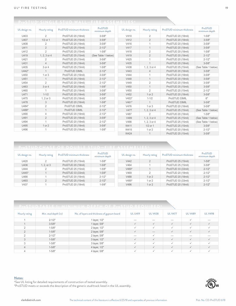
U L® F I R E T E S T I N G
ProS T U D C H A S E O R D O U B L E S T U D — F I R E A S S E M B L I E S A
ProS T U D T A B L E 1 : M I N I M U M D E P T H O F P r o S T U D R E Q U I R E D A
UL design no. Hourly rating ProSTUD minimum thickness ProSTUD minimum depth
U420 2 ProSTUD 25 (15mil) 1-5/8"U436 1, 2, or 3 ProSTUD 20 (18mil) 1-5/8"U444 2 ProSTUD 25 (15mil) 1-5/8"
U445* 1 ProSTUD 33 (33mil) 1-5/8"U466 1 ProSTUD 20 (18mil) 2-1/2"U493 2 ProSTUD 25 (15mil) 2-1/2"V437 1 ProSTUD 20 (18mil) 1-5/8"
UL design no. Hourly rating ProSTUD minimum thickness ProSTUD minimum depth
V442 2 ProSTUD 25 (15mil) 1-5/8"V464 1 ProSTUD 25 (15mil) 3-5/8"
V469* 1 ProSTUD 33 (33mil) 2-1/2"V469 2 ProSTUD 20 (18mil) 2-1/2"V488 1 or 2 ProSTUD 20 (18mil) 2-1/2"
V490* 1 or 2 ProSTUD 33 (33mil) 2-1/2"V496 1 or 2 ProSTUD 20 (18mil) 2-1/2"
Notes:ASee UL listing for detailed requirements of construction of tested assembly.*ProSTUD meets or exceeds the description of the generic stud/track listed in the UL assembly.
ProS T U D® S I N G L E S T U D W A L L — F I R E A S S E M B L I E S A
UL design no. Hourly rating ProSTUD minimum thickness ProSTUD minimum depth
U403 2 ProSTUD 20 (18mil) 3-5/8"U407 1/2 or 1 ProSTUD 25 (15mil) 3-5/8"U408 2 ProSTUD 20 (18mil) 3-5/8"U411 2 ProSTUD 25 (15mil) 2-1/2"U412 2 ProSTUD 25 (15mil) 1-5/8"U419 1, 2, 3 or 4 ProSTUD 25 (15mil) (See Table 1 below)U421 2 ProSTUD 25 (15mil) 3-5/8"U431 4 ProSTUD 20 (18mil) 3-5/8"U435 3 or 4 ProSTUD 25 (15mil) 1-5/8"
U442* 1 ProSTUD 33MIL 2-1/2"U450 1 or 3 ProSTUD 20 (18mil) 3-5/8"U451 1 ProSTUD 20 (18mil) 2-1/2"U454 2 ProSTUD 20 (18mil) 2-1/2"U463 3 or 4 ProSTUD 20 (18mil) 1-5/8"U465 1 ProSTUD 20 (18mil) 3-5/8"U471 1-1/2 ProSTUD 20 (18mil) 3-5/8"U475 1, 2 or 3 ProSTUD 20 (18mil) 3-5/8"U478 3 ProSTUD 20 (18mil) 1-5/8"
U484* 2 ProSTUD 33MIL 2-1/2" U488* 1 ProSTUD 33MIL 2-1/2"U490 4 ProSTUD 20 (18mil) 2-1/2"U491 2 ProSTUD 20 (18mil) 3-5/8"U494 1 ProSTUD 20 (18mil) 2-1/2"U495 1 or 2 ProSTUD 20 (18mil) 3-5/8"U496 1 ProSTUD 20 (18mil) 1-5/8"
UL design no. Hourly rating ProSTUD minimum thickness ProSTUD minimum depth
V410 2 ProSTUD 20 (18mil) 1-5/8"V412 2 ProSTUD 20 (18mil) 3-5/8"V416 1 ProSTUD 20 (18mil) 3-5/8"V417 1 ProSTUD 20 (18mil) 3-5/8"V418 2 ProSTUD 20 (18mil) 1-5/8"V419 2 ProSTUD 20 (18mil) 2-1/2"V425 1 ProSTUD 20 (18mil) 2-1/2"V435 1 ProSTUD 20 (18mil) 3-5/8"V438 1, 2, 3 or 4 ProSTUD 25 (15mil) (See Table 1 below)V443 4 ProSTUD 20 (18mil) 3-5/8"V444 1 ProSTUD 20 (18mil) 3-5/8"V448 1 ProSTUD 20 (18mil) 3-5/8"V449 2 ProSTUD 20 (18mil) 3-5/8"V450 1 ProSTUD 25 (15mil) 3-5/8"V450 2 ProSTUD 25 (15mil) 2-1/2"V452 1 or 2 ProSTUD 20 (18mil) 3-5/8"
V453* 1-1/2 ProSTUD 33MIL 6" V461* 1 ProSTUD 33MIL 3-5/8"V476 1 or 3 ProSTUD 20 (18mil) 3-5/8" V477 1, 2, 3 or 4 ProSTUD 25 (15mil) (See Table 1 below)V487 2 ProSTUD 20 (18mil) 1-5/8" V489 1, 2, 3 or 4 ProSTUD 25 (15mil) (See Table 1 below)V498 1, 2, 3 or 4 ProSTUD 25 (15mil) (See Table 1 below)W411 1/2 or 1 ProSTUD 25 (15mil) 3-5/8"W415 1 or 2 ProSTUD 20 (18mil) 2-1/2"W424 1 ProSTUD 25 (15mil) 3-5/8"
Hourly rating Min. stud depth (in) No. of layers and thickness of gypsum board UL U419 UL V438 UL V477 UL V489 UL V498
1 2-1/2" 1 layer, 1/2" — — — —1 3-5/8" 1 layer, 5/8"
2 1-5/8" 2 layer, 1/2"
2 1-5/8" 2 layer, 5/8" —
2 2-1/2" 2 layer, 5/8" — — — —3 1-5/8" 3 layer, 1/2"
3 1-5/8" 3 layer, 5/8"
4 1-5/8" 4 layer, 1/2"
4 1-5/8" 4 layer, 5/8"
19

The technical content of this literature is effective 6/25/18 and supersedes all previous information.Pub. No. CD-ProSTUD 6/18 clarkdietrich.com
C O N N E C T I O N S
Head-of-wall vertical deep leg deflection track systems are required to allow the top of the wall stud to float within the top track legs. This condition allows for vertical live load movement of the primary structure without transferring axial loads to the interior drywall studs. A gap (determined by the Engineer of Record) is required between the top of the wall stud and the deflection track. ProSTUD® Drywall Framing studs can be used with the three Deep Leg Track Systems listed below:
(1) WAFER HEAD FRAMINGSCREW IN EACH STUD FLANGE.PLACE IN CENTER OF SLOT.
(1) WAFER HEAD FRAMINGSCREW IN EACH STUD FLANGE.
PLACE IN CENTER OF SLOT.
(1) WAFER HEAD FRAMINGSCREW IN EACH STUD FLANGE.PLACE IN CENTER OF SLOT.
(1) WAFER HEAD FRAMINGSCREW IN EACH STUD FLANGE.
PLACE IN CENTER OF SLOT.
Details shown are for example only. The engineer of record of the project is responsible for the design of the connection to the structure. Additional connection details can be found at clarkdietrich.com.
ProTRAK® Deep Leg TrackProTRAK deep leg track is available with leg lengths of 2," 2-1/2" and 3" long. The wall studs are not fastened to the deflection track, and a row of lateral bracing is required within 12" of the deep leg track to prevent rotation and lateral movement of the studs. The deflection track system must be designed for the end reaction of the wall studs (point loads) and for the specific gap required for vertical deflection.
Structural Deep Leg Track (18ga & 16ga)Structural Deep Leg Track systems are installed the same as the ProTRAK deep leg track system but are designed to handle tall wall systems.For structural deep leg track allowable loads, contact Technical Services at 888-437-3244 or visit clarkdietrich.com.
ClarkDietrich offers both the MaxTrak® Slotted Deflection Track and BlazeFrame® Integrated Fire Stop System. Find more information on these systems at clarkdietrich.com.
Slotted Deflection Track from ClarkDietrichThe slotted deflection track is attached to the wall studs through vertical slots using wafer head screws, creating a positive connection that allows for vertical movement and also eliminates the requirement for lateral bracing near the top of the wall stud.
Deflection track system
2" Leg Trackwith 1/2" Gap
2-1/2" Leg Trackwith 3/4" Gap
3" Leg Trackwith 1" Gap
Allowableload (lbs)
Limitingwall height
Allowableload (lbs)
Limitingwall height
Allowableload (lbs)
Limitingwall height
Deflection track system
ProSTUD 25 (15mil, 50ksi)
ProSTUD 20 (18mil, 70ksi)
ProSTUD 30mil (33ksi)
ProSTUD 25 33mil (33ksi)
Allowable load (lbs)
Limiting wall height
Allowable load (lbs)
Limiting wall height
Allowable load (lbs)
Limiting wall height
Allowable load (lbs)
Limiting wall height
MaxTrak 30MIL 45 13' 6" 76 22' 10" 148 44' 4" 148 44' 4"MaxTrak 33MIL 52 15' 7" 88 26' 5" 156 46' 10" 156 46' 10"
D E E P L E G D E F L E C T I O N T R A C K S Y S T E M S
ProTRAK 25 36 10' 8" 24 7' 2" 18 5' 4"ProTRAK 20 52 15' 6" 34 10' 4" 26 7' 9"
ProTRAK 30MIL 92 27' 6" 61 18' 4" 46 13' 9"ProTRAK 33MIL 113 33' 10" 75 22' 7" 56 16' 11"
Complete information on Allowable Loads is available at clarkdietrich.com.
Notes:– Limiting wall heights are based on studs spaced at 16" o.c. and an interior lateral load of 5psf.– Stud members must be analyzed independently of the track system. Use www.iProSTUD.com to check
limiting wall heights for ProSTUD members.– Stud failure modes relating to the deflection track connection (shear, web crippling, etc.) must be
checked separately.
Notes:– Allowable loads are based on screws through the slots located 1-1/4" from the track web.– #8 minimum wafer head screws shall be used for stud-track connection.– The above table is applicable to ProSTUD members only. ProSTUD allowable heights must be checked also.– Allowable heights are based on 5psf and wall stud spacing at 16" o.c. with a max. gap of 7/8."
ProTRAK® Allowable Lateral Loads and Wall Heights
MaxTrak™ Allowable Lateral Loads and Wall Heights
20

Notes:– For unbraced sections, allowable moment is based on 2012 AISI Specification Section C3.1.2 with weak axis and torsional unbraced length assumed to be the listed span
(completely unbraced). For mid-span braced sections, allowable moment based on 2012 AISI Specification Section C3.1.2 with weak axis and torsional unbraced length assumed to be one-half of the listed span (bracing at mid-span).
– Web crippling calculation based on bearing length = 1 inch.– Web crippling and shear capacity have not been reduced for punchouts. If web punchouts occur near support members must be checked for reduced shear and web
crippling in accordance with the 2012 AISI Specification.– Values are for simple span conditions.e Web stiffeners required at support.
The technical content of this literature is effective 6/25/18 and supersedes all previous information. The technical content of this literature is effective 6/25/18 and supersedes all previous information. Pub. No. CD-ProSTUD 6/18clarkdietrich.com
A L L O W A B L E C E I L I N G S P A N S
Deflection Limit L/240
Deflection Limit L/360
ProS T U D ® A L LOWA B L E C E I L I N G S PA N S
ProS T U D A L LOWA B L E C E I L I N G S PA N S
Section Fy(ksi)
4psfLateral Support of Compression Flange
6psfLateral Support of Compression Flange
Unsupportedjoist spacing (in) o.c.
Mid-spanjoist spacing (in) o.c.
Unsupportedjoist spacing (in) o.c.
Mid-spanjoist spacing (in) o.c.
12 16 24 12 16 24 12 16 24 12 16 24162PDS125-15 50 7' 3" 6' 8" 5' 11" 7' 10" 7' 2" 6' 3" 6' 5" 5' 11" 5' 3" 6' 10" 6' 3" 5' 5" 250PDS125-15 50 8' 4" 7' 8" 6' 11" 10' 11" 9' 11" 8' 8" 7' 5" 6' 11" 6' 2" 9' 7" 8' 8" 7' 7" 362PDS125-15 50 9' 2" 8' 6" 7' 7" 12' 9" 11' 8" 10' 3" 8' 3" 7' 7" 6' 9" 11' 3" 10' 3" 8' 11" e400PDS125-15 50 9' 5" 8' 9" 7' 10" 13' 1" 12' 0" 10' 7" e 8' 6" 7' 10" 6' 11" e 11' 7" e 10' 7" e 9' 3" e600PDS125-15 50 10' 8" 9' 10" 8' 10" 15' 0" 13' 9" 12' 2" 9' 6" 8' 10" 7' 11" 13' 3" 12' 2" 9' 11" e162PDS125-18 70 7' 10" 7' 3" 6' 6" 8' 4" 7' 7" 6' 8" 7' 1" 6' 6" 5' 9" 7' 4" 6' 8" 5' 10" 250PDS125-18 70 9' 0" 8' 5" 7' 7" 11' 9" 10' 8" 9' 4" 8' 2" 7' 7" 6' 9" 10' 3" 9' 4" 8' 2" 362PDS125-18 70 9' 11" 9' 2" 8' 3" 14' 1" 12' 11" 11' 6" 8' 11" 8' 3" 7' 5" 12' 6" 11' 6" 10' 2" 400PDS125-18 70 10' 2" 9' 5" 8' 6" 14' 6" 13' 4" 11' 10" 9' 2" 8' 6" 7' 8" 12' 11" 11' 10" 10' 6" 600PDS125-18 70 11' 10" 10' 11" 9' 10" 16' 10" 15' 6" 13' 10" 10' 7" 9' 10" 8' 10" 15' 0" 13' 10" 12' 3"162PDS125-30 33 9' 4" 8' 7" 7' 8" 9' 10" 9' 0" 7' 10" 8' 3" 7' 8" 6' 10" 8' 7" 7' 10" 6' 10" 250PDS125-30 33 10' 4" 9' 7" 8' 6" 13' 8" 12' 5" 10' 10" 9' 3" 8' 6" 7' 8" 11' 11" 10' 10" 9' 6" 362PDS125-30 33 11' 3" 10' 5" 9' 4" 16' 2" 15' 0" 13' 6" 10' 1" 9' 4" 8' 5" 14' 7" 13' 6" 12' 0" 400PDS125-30 33 11' 7" 10' 9" 9' 8" 16' 8" 15' 6" 13' 11" 10' 5" 9' 8" 8' 8" 15' 0" 13' 11" 12' 5" 600PDS125-30 33 13' 1" 12' 2" 10' 11" 18' 11" 17' 6" 15' 8" 11' 9" 10' 11" 9' 10" 17' 0" 15' 8" 14' 1" 162PDS125-33 33 9' 9" 9' 0" 8' 0" 10' 4" 9' 4" 8' 2" 8' 8" 8' 0" 7' 1" 9' 0" 8' 2" 7' 2" 250PDS125-33 33 10' 9" 9' 11" 8' 10" 14' 3" 12' 11" 11' 3" 9' 7" 8' 10" 7' 11" 12' 5" 11' 3" 9' 10" 362PDS125-33 33 11' 8" 10' 9" 9' 8" 16' 8" 15' 5" 13' 11" 10' 5" 9' 8" 8' 8" 15' 0" 13' 11" 12' 6" 400PDS125-33 33 12' 0" 11' 1" 9' 11" 17' 2" 15' 11" 14' 4" 10' 9" 9' 11" 8' 11" 15' 5" 14' 4" 12' 10" 600PDS125-33 33 13' 6" 12' 6" 11' 3" 19' 6" 18' 1" 16' 3" 12' 2" 11' 3" 10' 1" 17' 6" 16' 3" 14' 7"
Section Fy(ksi)
4psfLateral Support of Compression Flange
6psfLateral Support of Compression Flange
Unsupportedjoist spacing (in) o.c.
Mid-spanjoist spacing (in) o.c.
Unsupportedjoist spacing (in) o.c.
Mid-spanjoist spacing (in) o.c.
12 16 24 12 16 24 12 16 24 12 16 24162PDS125-15 50 6' 10" 6' 3" 5' 5" 6' 10" 6' 3" 5' 5" 6' 0" 5' 5" 4' 9" 6' 0" 5' 5" 4' 9" 250PDS125-15 50 8' 4" 7' 8" 6' 11" 9' 7" 8' 8" 7' 7" 7' 5" 6' 11" 6' 2" 8' 4" 7' 7" 6' 8" 362PDS125-15 50 9' 2" 8' 6" 7' 7" 12' 9" 11' 7" 10' 1" 8' 3" 7' 7" 6' 9" 11' 2" 10' 1" 8' 10" e400PDS125-15 50 9' 5" 8' 9" 7' 10" 13' 1" 12' 0" 10' 7" e 8' 6" 7' 10" 6' 11" e 11' 7" e 10' 7" e 9' 3" e600PDS125-15 50 10' 8" 9' 10" 8' 10" 15' 0" 13' 9" 12' 2" 9' 6" 8' 10" 7' 11" 13' 3" 12' 2" 9' 11" e162PDS125-18 70 7' 4" 6' 8" 5' 10" 7' 4" 6' 8" 5' 10" 6' 5" 5' 10" 5' 1" 6' 5" 5' 10" 5' 1" 250PDS125-18 70 9' 0" 8' 5" 7' 7" 10' 3" 9' 4" 8' 2" 8' 2" 7' 7" 6' 9" 9' 0" 8' 2" 7' 2" 362PDS125-18 70 9' 11" 9' 2" 8' 3" 13' 9" 12' 6" 10' 11" 8' 11" 8' 3" 7' 5" 12' 0" 10' 11" 9' 6" 400PDS125-18 70 10' 2" 9' 5" 8' 6" 14' 6" 13' 4" 11' 8" 9' 2" 8' 6" 7' 8" 12' 10" 11' 8" 10' 2" 600PDS125-18 70 11' 10" 10' 11" 9' 10" 16' 10" 15' 6" 13' 10" 10' 7" 9' 10" 8' 10" 15' 0" 13' 10" 12' 3"162PDS125-30 33 8' 7" 7' 10" 6' 10" 8' 7" 7' 10" 6' 10" 7' 6" 6' 10" 6' 0" 7' 6" 6' 10" 6' 0" 250PDS125-30 33 10' 4" 9' 7" 8' 6" 11' 11" 10' 10" 9' 6" 9' 3" 8' 6" 7' 8" 10' 5" 9' 6" 8' 3" 362PDS125-30 33 11' 3" 10' 5" 9' 4" 15' 11" 14' 6" 12' 8" 10' 1" 9' 4" 8' 5" 13' 11" 12' 8" 11' 1" 400PDS125-30 33 11' 7" 10' 9" 9' 8" 16' 8" 15' 6" 13' 9" 10' 5" 9' 8" 8' 8" 15' 0" 13' 9" 12' 0" 600PDS125-30 33 13' 1" 12' 2" 10' 11" 18' 11" 17' 6" 15' 8" 11' 9" 10' 11" 9' 10" 17' 0" 15' 8" 14' 1" 162PDS125-33 33 9' 0" 8' 2" 7' 2" 9' 0" 8' 2" 7' 2" 7' 10" 7' 2" 6' 3" 7' 10" 7' 2" 6' 3" 250PDS125-33 33 10' 9" 9' 11" 8' 10" 12' 5" 11' 3" 9' 10" 9' 7" 8' 10" 7' 11" 10' 10" 9' 10" 8' 7" 362PDS125-33 33 11' 8" 10' 9" 9' 8" 16' 6" 15' 0" 13' 2" 10' 5" 9' 8" 8' 8" 14' 5" 13' 2" 11' 6" 400PDS125-33 33 12' 0" 11' 1" 9' 11" 17' 2" 15' 11" 14' 3" 10' 9" 9' 11" 8' 11" 15' 5" 14' 3" 12' 5" 600PDS125-33 33 13' 6" 12' 6" 11' 3" 19' 6" 18' 1" 16' 3" 12' 2" 11' 3" 10' 1" 17' 6" 16' 3" 14' 7"
21

The technical content of this literature is effective 6/25/18 and supersedes all previous information.
ClarkDietr ich L E E D® I N F O R M A T I O N A N D R E Q U I R E M E N T S
Environmental Product Declarations (EPD) ClarkDietrich, the largest manufacturer of cold-formed steel framing in North America, announced July 2015 a milestone in its ongoing commitment to supplying high-quality, environmentally responsible products. ClarkDietrich received third party-verified ISO-compliant Environmental Product Declarations (EPDs) for its complete steel product portfolio, including its popular ProSTUD® and ProSTUD® with DiamondPlus® Steel Framing Systems.
An EPD is a standardized, internationally recognized, comprehensive tool for providing information on a product’s environmental impact. Verified by a third party, information in the document is based on an ISO-compliant Life Cycle Assessment (LCA). This detailed analysis considers all processes in the life cycle of a product, including raw material extraction and refining, energy use and efficiency during manufacture, in addition to transportation methods.
Health Product Declarations (HPDs)ClarkDietrich also has Health Product Declarations (HPDs) for its complete steel product portfolio. The HPD Standard is solely a declaration of product content and direct health hazards associated with exposure to its individual contents.
ClarkDietrich plant locations:
ClarkDietrich LEED ServicesClarkDietrich is an active member of the U.S. Green Building Council with LEED® Accredited Professionals on staff. ClarkDietrich is committed to supplying quality products and continually looking for new ways to develop greener building products and sustainable business practices.
In total, ClarkDietrich products can help your project qualify for up to:
• 7 LEED points under LEED v4 for BD+C
• 7 LEED points under LEED 2009 (LEED-NC Version 2.2 and 3.0)
L E E D® I N F O R M A T I O N
Riverside, CASacramento, CABristol, CTDade City, FLMiami, FL
McDonough, GARochelle, ILBaltimore, MDO'Fallon, MOWarren, OH
Vienna, OHBaytown, TX Dallas, TX
ClarkDietrich LEED Request Form online at clarkdietrich.com
22

The technical content of this literature is effective 6/25/18 and supersedes all previous information. The technical content of this literature is effective 6/25/18 and supersedes all previous information. Pub. No. CD-ProSTUD 6/18clarkdietrich.com
Vienna, OHBaytown, TX Dallas, TX
P R O S T U D ® D R Y W A L L F R A M I N G S Y S T E M
S U P P O R T T O O L S
clarkdietrich.com Visit to explore company information, design tools, technical documents, services and so much more. Featuring a unique product selector, our website is designed to deliver the details you want with a minimum number of clicks.
SubmittalPro®
We built this online technical submittal generator tool to make your job easier. Use it to quickly view data on our products and create your final submittal documents. Access SubmittalPro at clarkdietrich.com or on your desktop or smartphone.
iProSTUD.comGoing mobile? With your smartphone in hand, you can perform a fast, easy search, view ProSTUD limiting heights and even email submittal documents.
Architectural Specification ReviewOver time, project specifications can become outdated. For suggestions on how to improve the performance of your specifications, contact us about a complimentary review. Send us an email to [email protected].
Technical ServicesCount on ClarkDietrich Technical Services to respond to a variety of needs, from general questions on industry standards to specifics on accurate sizing. Call us at 888-437-3244.
23

The technical content of this literature is effective 6/25/18 and supersedes all previous information.Pub. No. CD-ProSTUD 6/18 clarkdietrich.com
ClarkDietrich has prepared this literature with the utmost diligence and care for accuracy and conformance to standards.
ClarkDietrich intends this information to be accurate, informative, and helpful as a selection guide for choosing ClarkDietrich Building System products. However, this information is only to be used for guidance and is not intended to replace the design, drawings, specifications, and decisions of a professional architect or engineer.
ClarkDietrich or its affiliates shall not be responsible for incidental or consequential damages, directly or indirectly sustained, nor for loss caused by application of our products for other than their intended uses. Our liability is limited to replacement of defective products. Claims shall be deemed waived unless they are made to us in writing within thirty (30) days of the date a problem was or reasonably should have been discovered.
ClarkDietrich reserves the right to modify or change any information contained in this literature without notification.
AISI S100-12 North American Specification for the Design of Cold-Formed Steel Structural Members
AISI S220-15 North American Standard for Cold-Formed Steel Framing—Nonstructural Members
ASTM American Society for Testing and MaterialsA1003 "Material specification for steel sheet mechanical and chemical requirements"
C645 "Standard Specification for Nonstructural Steel Framing Members"
C754 "Standard Specification for Installation of Steel Framing Members to Receive Screw-Attached Gypsum Panel Products"
C1002 "Standard Specification for Steel Self Piercing Tapping Screw for the Application of Gypsum Panel Products or Metal Plaster Bases to Wood Studs or Steel Studs"
E119 "Standard Test Methods for Fire Tests of Building Construction and Materials"
E72 "Standard Test Methods of Conducting Strength Tests of Panels for Building Construction"
E90 "Standard Test Method for Laboratory Measurement of Airborne Sound Transmission Loss of Building Partitions and Elements"
UL® Underwriters Laboratories testing standardUL 263 "Fire Tests of Building Construction and Materials"
Independent product testing and certificationSound ratings: (WEAL) Western Electro-Acoustic LaboratoryFire testing: (UL) Underwriters Laboratories Inc.
Multiple UL® design listings for ProSTUDOver 50 UL Designs. See UL file number R26512 for additional information.
ProS T U D® & ProT R A K® C O D E A P P R O VA L S A N D P E R F O R M A N C E S TA N D A R D SClarkDietrich® ProSTUD Drywall Framing System meets or exceeds these applicable performance standards.
USGBC and related logo is a trademark owned by the U.S. Green Building Council and is used by permission.
ClarkDietrich is a proud member of the Steel Framing Industry Association (SFIA). Check the updated list of Certified Production Facilities at Architectural Testing's website at www.archtest.com. Additional code approvals SFIA (Steel Framing Industry Association)Intertek CCRR0207.
L O C A T I O N S
ClarkDietrich Manufacturing and Sales Locations:
CALIFORNIA Riverside P 951.360.3500F 951.360.3333
CALIFORNIA Sacramento P 951.360.3500F 951.360.3333
CONNECTICUT Bristol P 866.921.0023F 860.584.6899
FLORIDA Dade CityP 352.518.4400F 352.518.4450
TEXAS Dallas P 214.350.1716F 214.350.7252
CLIP EXPRESS℠—East P 866.638.1908
CLIP EXPRESS—West P 530.406.3462
FLORIDA Miami P 800.648.4695 F 305.477.4108
GEORGIA McDonough P 678.304.5500F 678.304.5555
ILLINOIS RochelleP 800.659.0745F 513.645.0750
MARYLAND BaltimoreP 410.477.4000F 410.477.1550
MISSOURI O'FallonP 888.747.0220 F 636.300.0414
OHIO Warren East P 330.372.5564F 330.372.4055
OHIO Vienna P 330.372.4014F 330.372.1945
TEXAS Baytown P 281.383.1617F 281.573.1679
ClarkDietrich Engineering Services. A full spectrum of solutions. Toll-Free Phone: 877.832.3206Toll-Free Fax: 877.832.3208Technical Services: 888.437.3244Email: [email protected]
CENTRAL Crown Point, IN
NORTHEAST Bristol, CT
SOUTHEAST McDonough, GA
WEST Carlsbad, CA
UL® and UL® Design are service marks of Underwriters Laboratories, Inc.
For the complete listing of all Fire and Sound rated assemblies,visit www.clarkdietrich.com/testing-agencies.
LEED® Services BUILD GREEN with ClarkDietrich ClarkDietrich is an active member of the U.S. Green Building Council and is committed to supplying quality products that are environmentally responsible. We are continually working to develop greener building products and sustainable business practices. ClarkDietrich steel framing helps contribute points toward LEED® certification. For more details contact Technical Services at 888-437-3244 or visit www.clarkdietrich.com/LEED.
24
The technical content of this literature is effective 6/25/18 and supersedes all previous information.
CD-ProSTUD © 6/18 ClarkDietrichThe technical content of this literature is effective 6/25/18 and supersedes all previous information.
Turn to ClarkDietrich for a complete lineup of steel construction products and services nationwide:
Interior Framing∙Exterior Framing∙Interior Finishing∙Clips/Connectors∙Metal Lath/Accessories∙Engineering
9050 Centre Pointe Dr. Suite 400 West Chester, OH 45069
P 513.870.1100 F 513.870.1300
clarkdietrich.comClarkwestern Dietrich Building Systems LLC