stretchpro: a leg separation apparatus senior … of biomedical engineering lawrence technological...
TRANSCRIPT

StretchPRO: A Leg Separation Apparatus
Senior Project - 4013
Department of Biomedical Engineering
Lawrence Technological University
Team members: Kevin Ritchey (LTU), Norah Hammad (LTU), Brendan O’Neil (UDM), Arafat
Abdulmalek (UDM), David Duron (UDM), Austin Carlisle (UDM)
Advisor: Dr. Eric Meyer
Table of Contents
Abstract …………………………………………………………………………………………..3
Introduction and Background…………………………………………………………………..3
Market Analysis and Stakeholders……………………………………………………………..5
Initial Design Process…………………………………………………………………………….6
Final Design……………………………………………………………………………………..11
Final Specifications……………………………………………………………………………..14
Testing Methods, Results, and Analysis……………………………………………………….14
Discussion……………………………………………………………………………………….16
Project Relevance and Broader Impact……………………………………………………….17
Appendix A: Timelines………………………………………………………………………....18
Appendix B: Budgets…………………………………………………………………………...19
Appendix C: Division of Labor………………………………………………………………...20
Appendix D: References………………………………………………………………………..21

Abstract
StretchPRO is a leg separation device designed by Lawrence Technological University
biomedical engineering students in collaboration with University of Detroit Mercy mechanical
engineering and nursing students for our senior design project. The goal of the project was to
affect the life of our client by designing an assistive care device that will solve one or more of his
needs. Due to severe spasticity in his legs and groin, our client is unable to separate his legs
without the assistance of two or three people and sometimes wakes up with his legs crossed.
Therefore, there is a need for patients who suffer from spasticity in their legs and groin need to
be able to stretch and separate their legs without assistance, in a safe and effective manner. Our
device, the StretchPRO, achieves separation of the legs by way of a scissor jack that would
normally be used to change one’s tire. Two adjustable straps attach to the separator by way of
integrated bearing housings. Once both legs are strapped in and connected to the separator, the
user begins to slowly turn the crank in order to open the jack, thus separating the legs to his or
her comfort level.
Introduction and Background
Our client is a 46 year-old male who was involved in an accident with a drunk driver
while riding his motorcycle in 1993. The client sustained a partial spinal cord injury in the
accident and was subsequently diagnosed with Brown-Sequard Syndrome, a very rare condition
characterized by a lesion affecting only one half of the spinal cord. Patients suffering from
Brown-Sequard’s often experience loss of motor function and loss of vibration, position, and
deep touch sensation on the side of the cord damage. Additionally, they may experience loss of
pain, temperature, and light touch sensation on the unaffected side (figure 1).
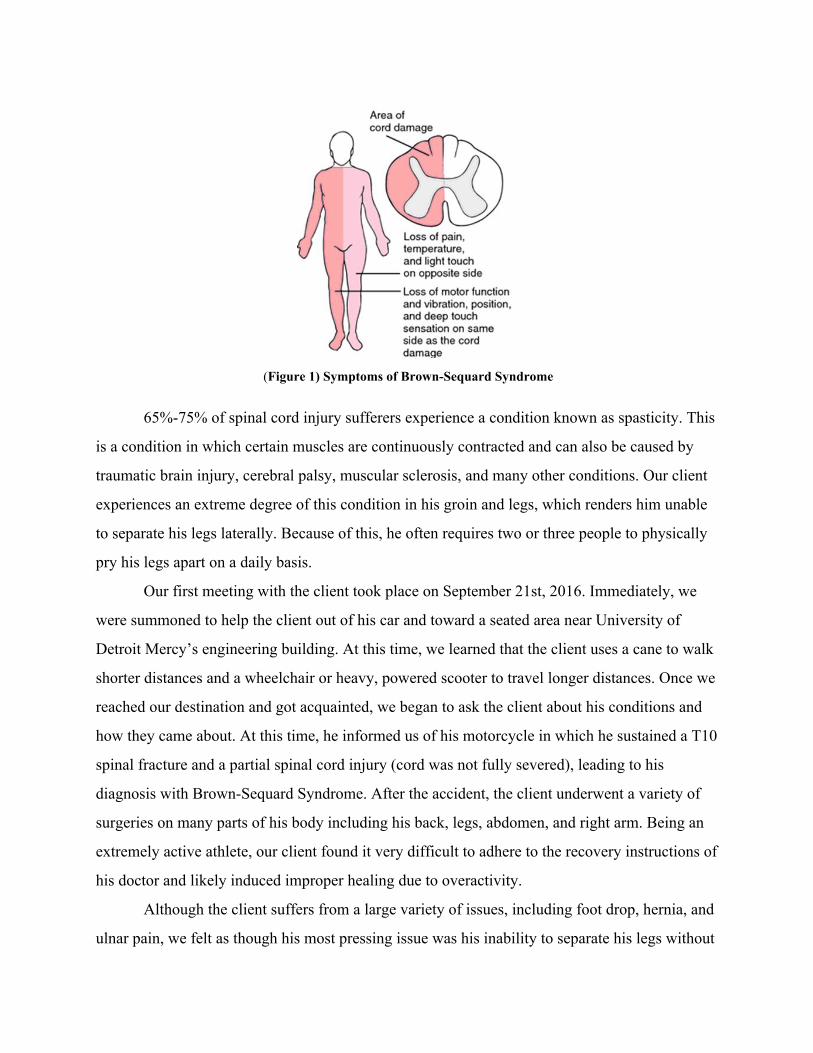
(Figure 1) Symptoms of Brown-Sequard Syndrome
65%-75% of spinal cord injury sufferers experience a condition known as spasticity. This
is a condition in which certain muscles are continuously contracted and can also be caused by
traumatic brain injury, cerebral palsy, muscular sclerosis, and many other conditions. Our client
experiences an extreme degree of this condition in his groin and legs, which renders him unable
to separate his legs laterally. Because of this, he often requires two or three people to physically
pry his legs apart on a daily basis.
Our first meeting with the client took place on September 21st, 2016. Immediately, we
were summoned to help the client out of his car and toward a seated area near University of
Detroit Mercy’s engineering building. At this time, we learned that the client uses a cane to walk
shorter distances and a wheelchair or heavy, powered scooter to travel longer distances. Once we
reached our destination and got acquainted, we began to ask the client about his conditions and
how they came about. At this time, he informed us of his motorcycle in which he sustained a T10
spinal fracture and a partial spinal cord injury (cord was not fully severed), leading to his
diagnosis with Brown-Sequard Syndrome. After the accident, the client underwent a variety of
surgeries on many parts of his body including his back, legs, abdomen, and right arm. Being an
extremely active athlete, our client found it very difficult to adhere to the recovery instructions of
his doctor and likely induced improper healing due to overactivity.
Although the client suffers from a large variety of issues, including foot drop, hernia, and
ulnar pain, we felt as though his most pressing issue was his inability to separate his legs without

assistance. The client often wakes up with his legs crossed or locked in the fetal position. To
combat this and other problems, he currently attends physical therapy at least three times per
week and receives therapeutic massage three times per week. He has also been prescribed muscle
relaxants but they were ineffective.
Other than the most common form of treatment for spasticity; the prescribing of muscle
relaxants such as Baclofen, Tizanidine, and Dantrolene (which can be very expensive, ranging in
cost from $120 to $4800 annually), there are limited options for those with lower limb and groin
spasticity. These include leg stretch machines (Figure 2) and leg separator pillows (Figure 3).
Leg stretch machines, more commonly used in flexibility training for gymnasts and martial
artists, can be quite heavy (50-75 lbs.), expensive ($175-$450), and cannot be used by our client
because of how close together his legs are in their initial position. Leg pillows, while cheap and
lightweight, are also much too wide to fit between our client’s legs and simply act as
placeholders (failing to offer active stretching and separation).
(Figure 2) Leg stretch machine (Figure 3) Leg separator pillow
Market Analysis and Stakeholders
Spasticity affects more than an estimated 12 million people worldwide. Two of the most
common causes of spasticity are cerebral palsy and muscular sclerosis. In fact, about 80%
(400,00) of the approximately 500,000 cerebral palsy patients in the United States suffer from
some form of spasticity, as do about 80% (320,000) of the 400,000 country’s M.S. patients. And
additionally, as previously stated, 65% to 78% of those with spinal cord injuries suffer from
spasticity.
Conservatively, if only 10% of spasticity sufferers worldwide required a device to
separate their legs at roughly $200 per unit, this would amount to a total cost of $240 million.
Lower extremity spasticity is known to be quite common in CP and MS patients, so assuming a
slightly higher, yet still conservative figure of 25% of these individuals each purchases such a
device, this would amount to $20 million and $16 million, respectively. Lastly, if 10$ of the SCI
patients affected by spasticity required a leg stretching device, this would amount to a total of
$3.12 million to $5.26 million.
The primary stakeholders for this device are the patients who cannot separate their legs
without assistance. They have a vested interest in being able to accomplish this very basic task
and would likely be purchasing the device for themselves unless it became classified as a
medical device. In this case, insurance companies would become major stakeholders. These
companies are going to want to put their money up for products that will be effective and reliable
so as not to require multiple purchases. Caregivers also hold a stake in this situation, as the
StretchPRO will eliminate one or more of their tasks by creating independence and mobility for
the patient.
Initial Design Process
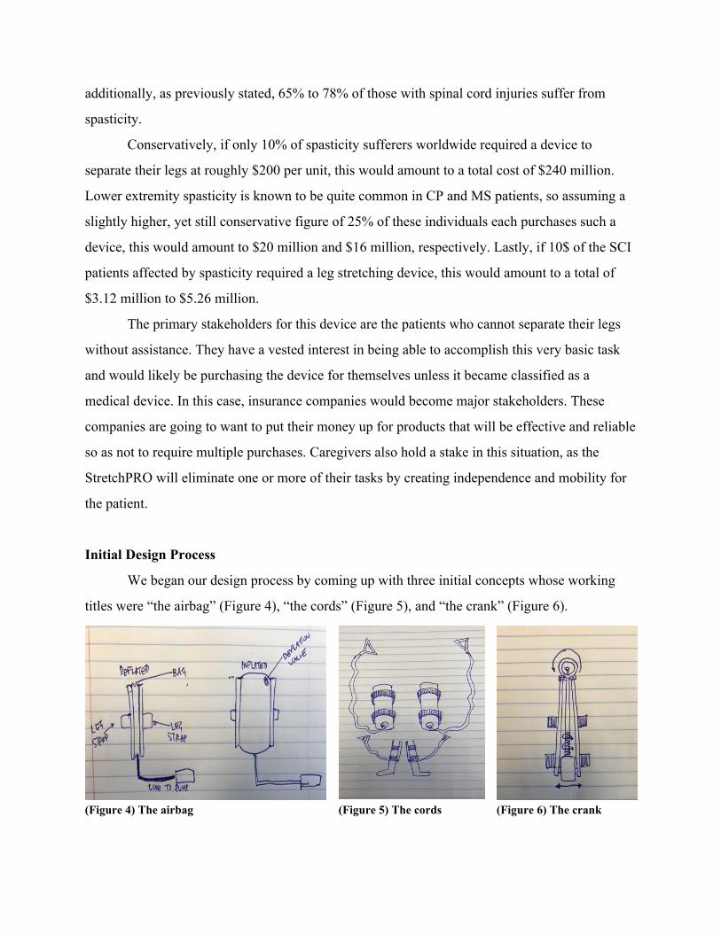
We began our design process by coming up with three initial concepts whose working
titles were “the airbag” (Figure 4), “the cords” (Figure 5), and “the crank” (Figure 6).
(Figure 4) The airbag (Figure 5) The cords (Figure 6) The crank

The airbag concept consisted of two leg braces attached to a centrally located air bladder
that would be inflated with a standard mattress pump. This design’s ability to minimize its width
would allow it to be placed between the client’s legs with little to no difficulty. Although the
design would be very lightweight, portable and provide independence, we were concerned that
the patient would lack control of the separation unless we made extensive alterations to the
pump. There was also concern that, when inflated, the device would be quite uncomfortable for
the client. Our second design was based around a pair of cords that the patient would strap to his
ankles and use to pull manually his legs apart. We considered this design because of its extreme
level of portability and its ability to provide independence, but quickly determined that this
design would be difficult to make ergonomic and would depend heavily on the client’s strength
level. The crank design was based on existing leg stretch machines wherein the user turns a
crank-wheel which, in turn, separates the legs. This design differed from its inspiration by its
lack of a seat and heavy leg rests (for portability) and different separation mechanism (although
undetermined at the time).
After many discussions among the group and with the client, we decided to move
forward with an improved version of the crank design; the StretchPRO (Figures 7, 8, and 9). The
first iteration of the StretchPRO consisted of three main components; the separator and two
locking leg stabilizers. The separator was originally made up of a scissor jack (usually used for
changing tires) and two steel plates, each with the male leaf of a lift-off hinge welded on. We
decided that the jack should be situated above the patient’s legs as opposed to between them in
order to insure that the device fit comfortably between the legs, hence the use of the tapering
plates. Although aluminum was briefly considered for the plate material, we eventually decided
that steel would be the better choice due its strength as well as the complexity of welding
aluminum to steel (which the jack’s frame is made out of).
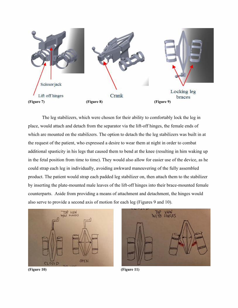
(Figure 7) (Figure 8) (Figure 9)
The leg stabilizers, which were chosen for their ability to comfortably lock the leg in
place, would attach and detach from the separator via the lift-off hinges, the female ends of
which are mounted on the stabilizers. The option to detach the the leg stabilizers was built in at
the request of the patient, who expressed a desire to wear them at night in order to combat
additional spasticity in his legs that caused them to bend at the knee (resulting in him waking up
in the fetal position from time to time). They would also allow for easier use of the device, as he
could strap each leg in individually, avoiding awkward maneuvering of the fully assembled
product. The patient would strap each padded leg stabilizer on, then attach them to the stabilizer
by inserting the plate-mounted male leaves of the lift-off hinges into their brace-mounted female
counterparts. Aside from providing a means of attachment and detachment, the hinges would
also serve to provide a second axis of motion for each leg (Figures 9 and 10).
(Figure 10) (Figure 11)

Once the patient’s legs were strapped in and the leg braces were attached to the separator,
the patient would begin to slowly turn the crank wheel to his desired level of comfort and
separation. The crank mechanism essentially elongates the jack’s existing screw and translates
the rotational motion of the crank 90 degrees in order to separate the jack using a 2:1 ratio bevel
gear box (Figure 12).
(Figure 12)
Next, we began to establish more detailed parameters to aid in the refinement of the
design (Figure 13).
(Figure 13)
● After researching the weights of other portable products on the market, we
decided to aim for a weight of under 10 pounds for our device. We felt as
though the client would be more than capable of lifting an item of this weight and
that it would be a drastic improvement over existing device that weight 4 to 6 as
much.
● Next, in the name of portability and taking the size of most available scissor jacks,
we decided to try to keep the device under 2 feet in length and 12 inches in
width (when in closed position, as measured from the top).
● Another very important parameter was the initial width of the part of the device
that would be inserted between the client’s legs. We felt that an initial width of
under 6 inches would be ideal for the device, based on measurement we took of
the client (discussed in the next section).
● In order for the device to be easy for the client to operate, we wanted the crank
arm to require no more than 10 pounds of force to turn. After witnessing the
client remove his heavy (80-100 lb.) power scooter from his trunk with no
assistance (at his request), we determined that he had considerable upper body
strength. However, we still did not want him to have to strain in order to use our
device, so we (mostly arbitrarily) picked this relatively low value for our desired
required force. We also picked a goal of under 5 minutes for the duration of time
required to achieve full separation, after seeing his normal stretching process.
● As far as cost, our goal was to design the device so that it could be sold at a price
below the average for most leg stretch machines (under $223).
● Our final design parameter was the desired degree of separation we wanted the
client to be able to achieve. Currently available leg stretch machines offer a

stretch of 180°, which would be equivalent to doing the splits. After witnessing
the degree of stretch that our client currently receives, we determined that half of
a full split (90°) would be more than sufficient.
Final Design:
With the aforementioned parameters in mind, we began to assemble a series of prototypes
for the purposes of testing and visualization. The first prototype was a very basic, proof of
concept version (Figure 14), which used a lab jack (instead of a scissor jack), and two pieces of
scrap aluminum from UDM’s metals shop. We briefly tested the prototype with our client by
having him insert the device between his legs and turn the knob. While the device was successful
at pushing his legs apart, the aluminum plates bent inward due to the force applied on them by
the client’s legs.
(Figure 14)
Our next prototype (Figure 15) was comprised of the aluminum scissor jack, and two
plates/rods that we designed and 3D printed at UDM (Figure 16). Because these custom
fabricated pieces were composed of a plastic material, we could not weld them and they had to
be fastened to the jack by way of screws and wing nuts. Also, before the plates/rods could be
fastened, the jack had to be modified so that both sides were flat. This required the removal of

the piece of the jack that is meant to make contact with the ground when using it to change tires
(Figure 17).
(Figure 16)
(Figure 15)
(Figure 17)
As you can see, we decided to change our method of interface between the separator to
the legs in a few ways. Instead of mounting lift-off hinges onto the plates/rods, we decided that
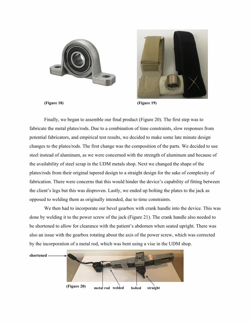
they could be inserted into bearing housings (Figure 18) that would be strapped onto the patient’s
legs (Figure 19). These straps could be worn over locking leg braces if the patient wanted to keep
his legs straight, or worn independently for stretching in a chair. Additionally, this method of
connection would still provide the additional axis of motion shown in figure 11. At this stage, we
simply asked the client to put the straps on, noting any difficulties he had in doing so. There were
none.
(Figure 18) (Figure 19)
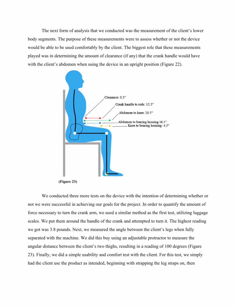
Finally, we began to assemble our final product (Figure 20). The first step was to
fabricate the metal plates/rods. Due to a combination of time constraints, slow responses from
potential fabricators, and empirical test results, we decided to make some late minute design
changes to the plates/rods. The first change was the composition of the parts. We decided to use
steel instead of aluminum, as we were concerned with the strength of aluminum and because of
the availability of steel scrap in the UDM metals shop. Next we changed the shape of the
plates/rods from their original tapered design to a straight design for the sake of complexity of
fabrication. There were concerns that this would hinder the device’s capability of fitting between
the client’s legs but this was disproven. Lastly, we ended up bolting the plates to the jack as
opposed to welding them as originally intended, due to time constraints.
We then had to incorporate our bevel gearbox with crank handle into the device. This was
done by welding it to the power screw of the jack (Figure 21). The crank handle also needed to
be shortened to allow for clearance with the patient’s abdomen when seated upright. There was
also an issue with the gearbox rotating about the axis of the power screw, which was corrected
by the incorporation of a metal rod, which was bent using a vise in the UDM shop.
(Figure 20)

(Figure 21)
Final Specifications:
(Figure 22)
Testing Methods, Results, and Analysis:
Our first test was a measurement of the force required to separate the patient’s legs via
force transducer luggage scales. To perform this test, we attached the luggage scales to each of
the patient’s ankles and physically separated them as he normally does. The purpose of this test
was to determine whether or not the jack’s force would be sufficient for stretching the client’s
legs. We found that approximately 287.5 pounds of force were required to achieve the separation
that the client needs on a daily basis, which is well below the scissor jack’s lift rating, which is
4000 pounds.
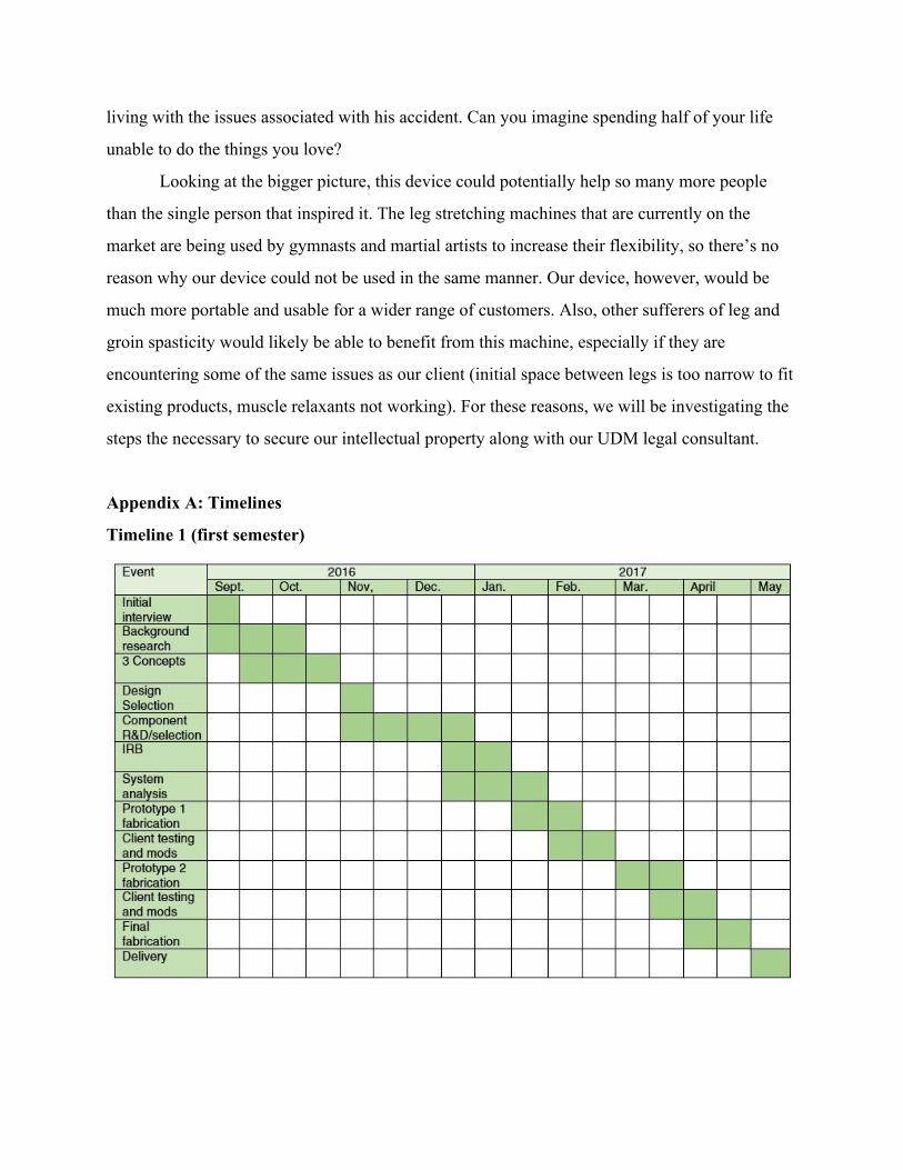
The next form of analysis that we conducted was the measurement of the client’s lower
body segments. The purpose of these measurements were to assess whether or not the device
would be able to be used comfortably by the client. The biggest role that these measurements
played was in determining the amount of clearance (if any) that the crank handle would have
with the client’s abdomen when using the device in an upright position (Figure 22).
(Figure 23)
We conducted three more tests on the device with the intention of determining whether or
not we were successful in achieving our goals for the project. In order to quantify the amount of
force necessary to turn the crank arm, we used a similar method as the first test, utilizing luggage
scales. We put them around the handle of the crank and attempted to turn it. The highest reading
we got was 3.8 pounds. Next, we measured the angle between the client’s legs when fully
separated with the machine. We did this buy using an adjustable protractor to measure the
angular distance between the client’s two thighs, resulting in a reading of 100 degrees (Figure
23). Finally, we did a simple usability and comfort test with the client. For this test, we simply
had the client use the product as intended, beginning with strapping the leg straps on, then

inserting the separator, and turning the crank to full separation. The client reported absolutely no
difficulty or discomfort and had zero complaints.
(Figure 24)
Discussion
Over the course of the year, many significant changes in StretchPRO’s design were
implemented. In fact, we ended up making changes up until the second to last week of the
semester. Our original plan to fabricate our tapered side plates out of aluminum changed to
straight plates made of steel. We had initially planned on welding them to the jack but decided to
bolt them on instead, as we were able to save money in doing so. We also had to add a stabilizing
rod to the crank mechanism to avoid rotation about the axis of the jack’s power screw.
Additionally, we were unable to find a bevel gearbox for a reasonable price and coincidently
found one (in our UDM teammate’s car) that had a crank handle attached to it. We decided to
use this gearbox even though its gear ratio was 1:1, instead of our desired 2:1. Another change
came in the form of our strap design. We had originally planned to mount male and female
hinges of lift-off hinges to the plates and braces, respectively. After much deliberation, we
decided to redesign our plates to be inserted in bearing housings that would be mounted to the
braces. This idea was further altered when we determined that mounting the bearing housings to
the braces would be extremely difficult, given their design. To overcome this, we designed straps
that would integrate the bearing housings within them. This also allowed the device to be used
with any brace of our client’s choosing. The final change was to forgo the incorporation of a
spandex casing for the device. Initially, we wanted to incorporate this element to avoid pinch
hazards and to make the device more visually appealing. After we had designed this part and
showed our client, he felt as though the device looked better without it and was not concerned
about any danger of pinching.

Even though we made a number of changes throughout the duration of the device’s
development, we still were able to meet or exceed all of our original goals. In addition to the
information given in figure 24, we were able to design a device with a final weight of only 6.4
pounds, which is 36% lighter than our target weight and 85.8% lighter than the lightest leg
stretch machine on the market (45 pounds). We also were able to keep the cost of the final design
at $138.98, which is 37.7% lower than our target price. Of course, we would have to add to this
figure for our selling price, but we feel as though further refinement of the device design and
manufacturing process would decrease the cost to make it. The width of the section of the device
that is inserted between the patient’s legs is only about 4 inches, which is 33.33% lower than our
target width, and 63.6% lighter than most leg stretch machines’ (11 inches). As far as ease of
operation, our device’s crank only requires 3.8 pounds of force to turn, a 62% improvement over
our goal. It also only takes 3 minutes and 45 seconds to reach full separation at a moderate crank
turning speed; 25% less time than we had originally aimed for. This could be improved by
implementing our desired gear ratio of 2:1.
Overall, our client was extremely happy with the device. He was able to easily use the
device to achieve a more than sufficient level of separation of his legs. When we spoke with him
at the VA presentation, he was elated to be able to forgo expensive and inconvenient physical
therapy sessions in favor of stretching his legs independently. The StretchPRO will allow our
client to save a large amount of valuable time that he loses to commuting to and participating in
physical therapy.
Project Relevance and Broader Impact
The StretchPRO device will allow our client to do something that most of us take for
granted on a daily basis: separate his legs independently. Because his stance is so narrow, our
client has difficulty walking in his current state and often does not have people to help him
stretch his legs. This is especially detrimental to his ability to participate in many activities with
his young daughter, as well as his ability to enjoy the athletic activities that he once loved, such
as golf, tennis, and basketball. Being 46 years old now, the client has spent the last half of his life
living with the issues associated with his accident. Can you imagine spending half of your life
unable to do the things you love?
Looking at the bigger picture, this device could potentially help so many more people
than the single person that inspired it. The leg stretching machines that are currently on the
market are being used by gymnasts and martial artists to increase their flexibility, so there’s no
reason why our device could not be used in the same manner. Our device, however, would be
much more portable and usable for a wider range of customers. Also, other sufferers of leg and
groin spasticity would likely be able to benefit from this machine, especially if they are
encountering some of the same issues as our client (initial space between legs is too narrow to fit
existing products, muscle relaxants not working). For these reasons, we will be investigating the
steps the necessary to secure our intellectual property along with our UDM legal consultant.
Appendix A: Timelines
Timeline 1 (first semester)

Timeline 2 (second semester):
Appendix B: Budgets
Budget 1 (first semester)
Item Cost Reasons
Ram Scissor Jack
$24.95
+ $11.26 shipping =
$36.21
- Lightweight (12 lbs.)
- 2500 lbs capacity
- 18-¾” lift (separation)
Ossur Knee
Immobilizers
$54.56 x 2
+ $6.55 sales tax =
$115.67
- Fully adjustable
- Provides immobilization in extended position
- Comfortable
3/16” A36 Steel
Plates
$15.34 x 2
+ $15.74 shipping =
$46.40
- Lightweight (7.66 lbs/each)
- 36,,000 psi yield strength
- Easy to weld, cut, form, and machine
Batallion Lift-off
Hinges
$7.59 x 2
+ $5.00 shipping =
$20.18
- 270 degree ROM
- Full surface mounting
- 88 lb load capacity
- 304 stainless
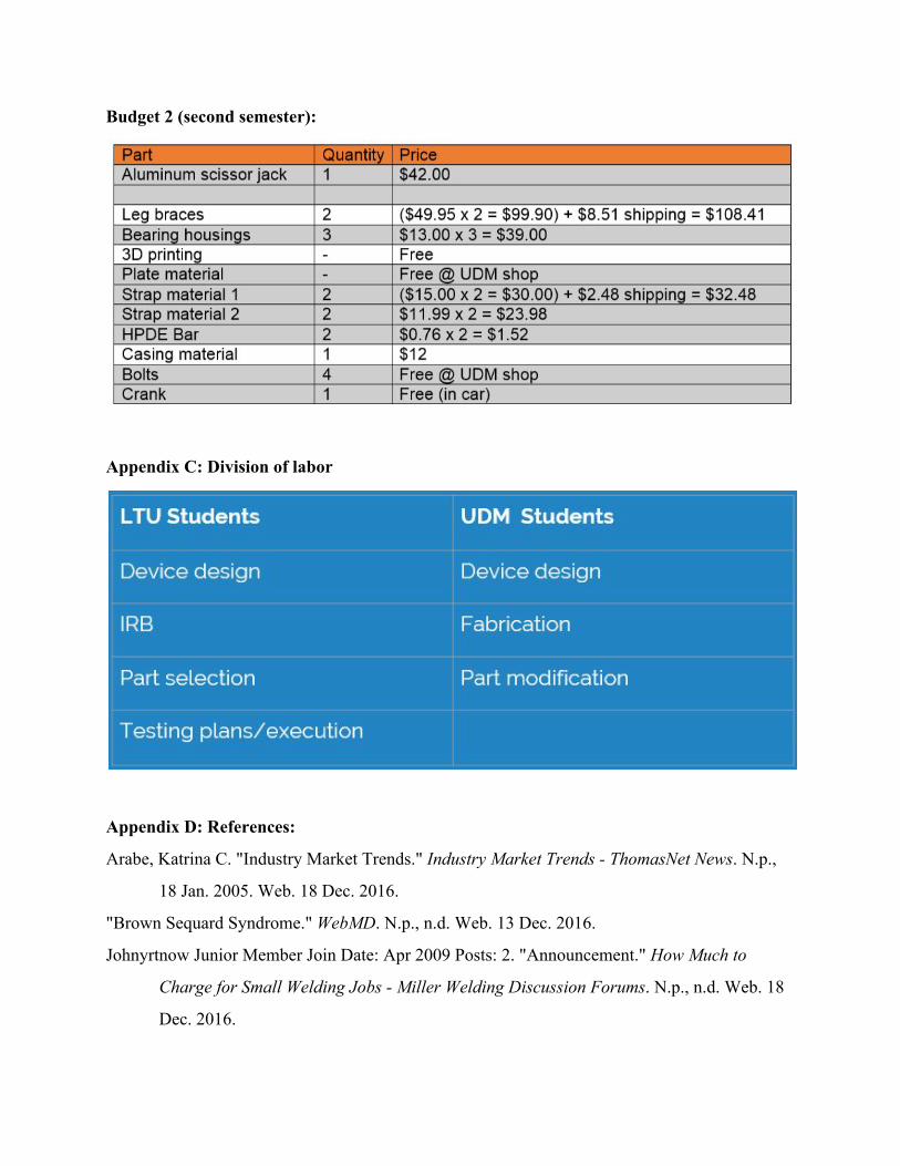
Budget 2 (second semester):
Appendix C: Division of labor
Appendix D: References:
Arabe, Katrina C. "Industry Market Trends." Industry Market Trends - ThomasNet News. N.p.,
18 Jan. 2005. Web. 18 Dec. 2016.
"Brown Sequard Syndrome." WebMD. N.p., n.d. Web. 13 Dec. 2016.
Johnyrtnow Junior Member Join Date: Apr 2009 Posts: 2. "Announcement." How Much to
Charge for Small Welding Jobs - Miller Welding Discussion Forums. N.p., n.d. Web. 18
Dec. 2016.

"Ossur Universal 3-Panel Knee Immobilizer." Ossur 3-Panel Immobilizer | The Brace Shop.
N.p., n.d.
Web. 18 Dec. 2016.
"Ram Scissor Stabilizer Jack - 18-3/4" Travel - 2,500 Lbs - Qty 1 Etrailer Camper Jack
TJSC-24."
Etrailer.com. N.p., n.d. Web. 18 Dec. 2016.
Saulino, Michael. "Economic Impact of Spasticity and Its Treatment." Spasticity: Diagnosis and
Management. 2nd ed. N.p.: Demos Medical, 2016. 479. Web. 1 Dec. 2016.
"Sports & Outdoors." Walmart.com. N.p., n.d. Web. 13 Dec. 2016.
"Steel Plate." MetalsDepot® - Buy A36 Steel Plate Online! N.p., n.d. Web. 18 Dec. 2016.
"The American Association of Neurological Surgeons." Spasticity. N.p., n.d. Web. 13 Dec. 2016.
Images:
“Bearing pillow block bearing housing 10mm.” Ali Express. N.p., n.d. Web. 21 April 2017
"Bevel Gears - WD Bearing Group." WD Bearing Group. N.p., n.d. Web. 18 Dec. 2016.
“Brown-Sequard syndrome.” The Free Dictionary. N.p., n.d. Web. 21 April 2017
“Handy Tips For Perfect Posture - All Day Long.” Life Jacks. N.p., n.d. Web. 21 April 2017
"New CleanBend Press Brake Tooling - Mate Precision Tooling." Mate Press Brake Tooling.
N.p., 08 Oct. 2015. Web. 17 Dec. 2016.
Nguyen, Chinh. "About." �CHINH'S ARCHITECTURE PORTFOLIO. N.p., n.d. Web. 13 Dec.
2016.
"NOVA Medical Products Cushion Knee Spacer." Amazon.com. N.p., n.d. Web. 13 Dec. 2016
"Sports & Outdoors." Walmart.com. N.p., n.d. Web. 13 Dec. 2016.
"UDM Color Seal." Wikipedia. N.p., n.d. Web.