stress and deformation analysis in base isolation elements
TRANSCRIPT

197
Claudiu Iavornic, Gilbert-Rainer Gillich, Vasile Iancu, Zeno-Iosif Praisach, Ovidiu Vasile
Stress and Deformation Analysis in Base Isolation Elements Using the Finite Element Method
In Modern tools as Finite Element Method can be used to study the be-havior of elastomeric isolation systems. The simulation results obtained in this way provide a large series of data about the behavior of elas-tomeric isolation bearings under different types of loads and help in taking right decisions regarding geometrical optimizations needed for improve such kind of devices.
Keywords: elastomeric isolation systems, earthquake, safety, finite element method
1. Introduction
The study of the laminated elastomeric isolation bearings began in 1949 when Haringx was the first who treated the bearing as an equivalent column with a con-stant cross section area, homogeneous and isotropic material, and an equivalent height that included the rubber layers and steel shims. From Haringx theory, the P–∆ effect on the influence of horizontal stiffness of the bearings under an axial compressive loading was studied. In the last 30 years different type of isolating and dissipation devices was developed. In 2000 year, another theory suggested a macroscopic model to study the mechanical behaviors and the stability analysis of multilayer elastomeric isolation bearings. In 2007 was started the investigation about tension buckling and related of that with compression buckling in the multi-layer elastomeric bearings.
Obviously the most studied phenomena is represented by detachment of the rubber from the steel or steel yielding. Therefore, it is necessary an accurate knowledge of the global characteristics and behavior of the device under maximum lateral displacement with various boundary conditions.
To estimate the performance of the multilayered laminated rubber bearings in order to find the optimum design, the usually method consisting in data obtained from expensive tests on prototypes or full scale devices.
ANALELE UNIVERSIT ĂłII
“EFTIMIE MURGU” RE ŞIłA
ANUL XVIII, NR. 1, 2011, ISSN 1453 - 7397

198
Another possibility is to use numerical procedure like the finite element method for predicting the behavior and performance of rubber damping device. In this paper will be presented results obtained by the FEM together with conclusions regarding the behavior of elastomeric bearings.
Today, elastomeric dumper is the most used isolator all over the world; they are in buildings, bridges and other civil structures. This new design technology has considerable potential in preventing earthquake damage of structures.
The isolation system reduces the effect of the horizontal components of the ground acceleration by interposing structural elements with low horizontal stiffness between the structure and the foundation. This gives the structure a fundamental frequency that is much lower than both its fixed-base frequency and the predomi-nant frequencies of the ground motion.
Most recent examples of isolated buildings use multilayered laminated rubber bearings with steel reinforcing layers. The structure of composite elements consist-ing in thin layers of natural or synthetic rubber bonded to steel plate. Therefore, the laminated elastomeric bearing has very high compression stiffness while retain-ing the characteristic low shear stiffness of rubber.
The isolation system does not absorb the earthquake energy, but deflects it through the reinforced parts of the system. The main advantage of this solution consist in: compact construction, long lasting non-degradable materials, easy to manufacture, no moving parts, reliable.
2. Analytical considerations
Elastomeric rubber bearings have finite vertical stiffness that affects the verti-cal response of the isolated structure. The vertical stiffness, kv, of an elastomeric rubber bearing can be obtained using the following formula:
tn
AEPk C
⋅⋅==
δ (1)
where: P vertical load; δ vertical displacement; EC compression modulus of elastomer; A cross sectional area of the bearing; n number of elastomeric layers; t thickness of each layer. Also some approximations have been proposed for calculating the compres-
sions modulus, the most acceptable expressions for circular bearings is presented:

199
1
2eff
C K3
4
SG6
1E
−
+
⋅= (2)
where: K bulk modulus S shape factor, defined as the ratio of the loaded area to the bonded perimeter of a single rubber layer. For a circular bearing of bonded diameter Ø and rubber layer thickness t, the
shape factor is given by:
t4S
Φ= (3)
Horizontal stiffness can be inferred by the expression:
tn
AGFkH ⋅
⋅==∆
(4)
F horizontal load; ∆ horizontal displacement; G shear modulus of elastomer. 3. FEM analysis
The three-dimensional representation of analyzed geometry and a sketch of that contain the main dimensions is represented in figure 1.
Figure 1. Sketch and 3D view of the sectioned bearing
200
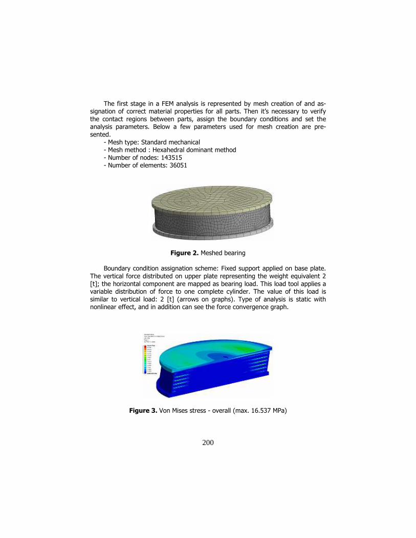
The first stage in a FEM analysis is represented by mesh creation of and as-signation of correct material properties for all parts. Then it’s necessary to verify the contact regions between parts, assign the boundary conditions and set the analysis parameters. Below a few parameters used for mesh creation are pre-sented.
- Mesh type: Standard mechanical - Mesh method : Hexahedral dominant method - Number of nodes: 143515 - Number of elements: 36051
Figure 2. Meshed bearing
Boundary condition assignation scheme: Fixed support applied on base plate. The vertical force distributed on upper plate representing the weight equivalent 2 [t]; the horizontal component are mapped as bearing load. This load tool applies a variable distribution of force to one complete cylinder. The value of this load is similar to vertical load: 2 [t] (arrows on graphs). Type of analysis is static with nonlinear effect, and in addition can see the force convergence graph.
Figure 3. Von Mises stress - overall (max. 16.537 MPa)

201
Figure 4. Convergence graph
Figure 2. Von Mises stress distribution in the base plate (max. 0.511 MPa)
Figure 6. Von Mises stress distribution in upper plate (max. 8.6082 MPa)

202
Figure 7. Von Mises stress distribution in the rubber volume (max.1.81 MPa)
Figure 8. Von Mises stress distribution in the 1st slide plate (max. 8.396 MPa)
Figure 9. Von Mises stress distribution in the 2nd slide plate (max. 15.709 MPa)

203
Figure 10. Von Mises stress in the 3th slide plate (max.16.078 MPa)
Figure 11. Von Mises stress in the 4th slide plate (max.16.537 MPa)
Figure 12. Von Mises stress in the 5th slide plate (max. 14.047 MPa)
204
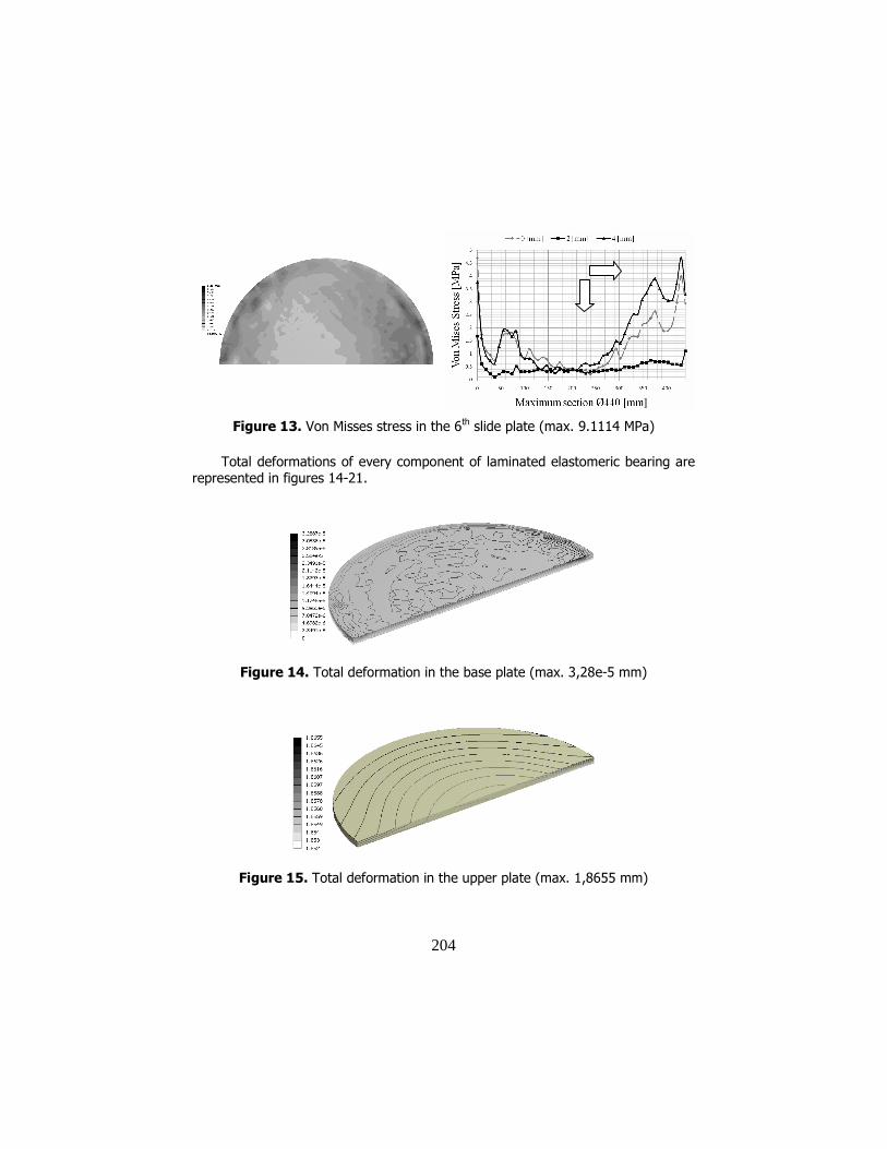
Figure 13. Von Misses stress in the 6th slide plate (max. 9.1114 MPa)
Total deformations of every component of laminated elastomeric bearing are
represented in figures 14-21.
Figure 14. Total deformation in the base plate (max. 3,28e-5 mm)
Figure 15. Total deformation in the upper plate (max. 1,8655 mm)

205
Figure 16. Total deformation in the 1st slide plate (max. 0,15788 mm)
Figure 17. Total deformation in the 2nd slide plate (max. 0.473)
Figure 18. Total deformation in the 3rd slide plate (max. 0.7769 mm)
Figure 19. Total deformation in the 4th slide plate (max.1.086 mm)

206
Figure 20. Total deformation in the 5th slide plate (max. 1.3943 mm)
Figure 21. Total deformation in the 6th slide plate (max. 1.7062 mm)
4. Conclusion
The analysis of stress and deformations in elastic bearing elements used in seismic isolation by means of Finite Elements Method analysis relive the critical points in/on the rubber or steel elements. In our study the maximum value of stress is obtained on the fourth slide plate nearly to the exterior edge in the middle of elastomeric volume. This value is an intrinsic result of frictional behavior be-tween the elastomeric volume and steel plate.
The plates are "welded" inside the rubber volume and have a different mode of response regarding loads. In order to reduce the stress value it is necessary to adopt different shapes for the two base and upper plates. The authors concern on the design and manufacturing of a new, innovative bearing, with a different shape, in order to reduce the stress between the elastomeric volume and the plates and to avoid in this way the appearance of gaps between this two types of constitutive elements.
207
Acknowledgements
The present work has been co-funded by the Sectoral Operational Programme Human Resources Development 2007-2013 of the Romanian Ministry of Labour, Family and Social Protection through the Financial Agreement POSDRU 62557 and POSDRU 5159.
References
[1] Amin A.F.M.S., Wiraguna S.I., Bhuiyan A.R., Okui Y., Hyperelasticity Model for Finite Element Analysis of Natural and High Damping Rubbers in Compression and Shear, Journal of Engineering Mechanics © ASCE / January 2006
[2] Azlan Adnan, Jati Sunaryati, Mechanical characteristics of circular elas-tomeric hollow rubber bearing, APSEC 2006, 5-6 September 2006, Kuala Lumpur, Malaysia
[3] Bhoje S.B., Chellapandi P., Chetal S., Muralikrishna R., Salvaraj T., Comparation of computer simulated and observed force deformation characteristics of anti-seismic devices and isolated structures, IAEA-TECDOC-1288, pp. 105-130
[4] Bratu P., Vibratiile sistemelor elastice, Editura Tehnică, Bucuresti, 2000 [5] Bratu P., Sisteme elastice de rezemare pentru masini si utilaje, Editura
Tehnica, Bucuresti, 1990 [6] Bratu P., Analiza sistemelor elastice. Comportarea la actiuni statice si
dinamice, Editura Impuls, Bucuresti, 2010 [7] Forni M., La Grotteria M., Martelli A., Verification and improvement of
analytical modeling of seismic isolation bearing and isolated structures, IAEA-TECDOC-1288, pp. 29-77
[8] Gracia L.A., Gómez B., Ahmadi H.R., Muhr A.H., Simulation of the ro-tary shear experiment through the overlay method, resursa Web
[9] Gillich G-R., Samoilescu G., Berinde F., Chioncel C.P., Experimental de-termination of the rubber dynamic rigidity and elasticity module by time-frequency measurements, Materiale Plastice Vol. 44 (2007), Issue 1, pp. 18-21
[10] Gillich G-R., Bratu P., Frunzaverde D., Amariei D., Iancu V., Identifying mechanical characteristics of materials with non-linear behavior using sta-tistical methods, 4th WSEAS International Conference on Computer En-gineering and Applications, Harvard University, Cambridge, January 27-29, 2010
[11] Nastac S., Analiza numerică cu aplicatii în inginerie mecanică, Editura Impuls, Bucuresti, 2004

208
[12] Nedelcu D., Gillich G-R., Cziple F., Padurean I., Considerations about using polymers in adaptive guardrails construction Materiale Plastice Vol. 45 (2008), Issue 1, pp. 47-52
[13] Shashikant Sharma, Critical comparison of popular hyper-elastic mate-rial models in design of anti-vibration mounts for automotive industry through FEA, resursa Web
[14] Suripa U., Chaikittiratana A., Finite element stress and strain analysis of a solid tyre, Journal of Achievements in Materials and Manufacturing Engineering, Vol. 31, Issue 2, December 2008
Addresses:
• Eng. Claudiu Iavornic, SC HYDROENGINEERING SA, Calea Caransebe-sului 16A, 320168, Resita, [email protected]
• Prof. Dr. Eng. Ec. Gilbert-Rainer Gillich, Universitatea “Eftimie Murgu” Resita, P-ta Traian Vuia 1-4, 320085, Resita, [email protected]
• Eng. Vasile Iancu, PhD. Student, Universitatea “Eftimie Murgu” Resita, P-ta Traian Vuia 1-4, 320085, Resita, [email protected]
• Dr. Eng. Zeno-Iosif Praisach, Universitatea “Eftimie Murgu” Resita, P-ta Traian Vuia 1-4, 320085, Resita, [email protected]
• Assit. Prof. Dr. Eng. Ovidiu Vasile, Universitatea “Eftimie Murgu” Resita, P-ta Traian Vuia 1-4, 320085, Resita, [email protected]