strength of materials -...
TRANSCRIPT
Strength of Materials 10CV33
Depatment Civil Engg., SJBIT Page 1
STRENGTH OF MATERIALS
(COMMON TO CV/TR/EV/CTM)
Sub Code : 10 CV 33 IA Marks : 25
Hrs/ Week : 04 Exam Hours : 03
Total Hrs. : 52 Exam Marks : 100
PART – A
UNIT 1:
Simple Stress and Strain
1.1 Introduction, 1.2 Properties of Materials, 1.3 Stress, Strain, Hook’s law, 1.4 Poisson’s
Ratio, 1.5 Stress – Strain Diagram for structural steel and non ferrous materials, 1.6 Principles
of superposition, 1.7 Total elongation of tapering bars of circular and rectangular cross
sections. Elongation due to self – weight
7 Hours
UNIT 2:
Simple Stress and Strain (continued…)
2.1 Composite section, 2.2 Volumetric strain, expression for volumetric strain, 2.3 Elastic
constants, relationship among elastic constants, 2.4 Thermal stresses (including thermal
stresses in compound bars).
6 Hours
UNIT 3:
Compound Stresses
3.1 Introduction, 3.2 Stress components on inclined planes, 3.3 General two dimensional
stress system, 3.4 Principal planes and stresses, 3.5 Mohr’s circle of stresses.
8 Hours
UNIT 4:
Bending Moment and Shear Force in Beams
4.1 Introduction, 4.2 Types of beams loadings and supports, 4.3 Shearing force in beam, 4.4
Bending moment, 4.5 Sign convention, 4.6 Relationship between loading, shear force and
bending moment, 4.7 Shear force and bending moment equations, SFD and BMD with salient
values for cantilever beams, simply supported beams and overhanging beams considering
point loads, UDL, UVL and Couple.
7 Hours
PART B
UNIT 5:
Bending Stress, Shear Stress in Beams
5.1 Introduction – Bending stress in beam, 5.2 Assumptions in simple bending theory,
5.3 Pure bending derivation of Bernoulli’s equation, 5.4 Modulus of rupture, section modulus,
Strength of Materials 10CV33
Depatment Civil Engg., SJBIT Page 2
5.5 Flexural rigidity, 5.6 Expression for horizontal shear stress in beam, 5.7 Shear stress
diagram for rectangular, symmetrical ‘I’ and ‘T’ section (Flitched beams not included).
6 Hours
UNIT 6:
Deflection of Beams
6.1 Introduction – Definitions of slope, deflection, 6.2 Elastic curve derivation of differential
equation of flexture, 6.3 Sign convention 6.4 Slope and deflection for standard loading classes
using Macaulay’s method for prismatic beams and overhanging beams subjected to point
loads, UDL and Couple.
6 Hours
UNIT 7:
Torsion of Circular Shafts
7.1 Introduction – Pure torsion-torsion equation of circular shafts, 7.2 Strength and stiffness,
7.3 Torsional rigidity and polar modulus, 7.4 Power transmitted by shaft of solid and hollow
circular sections.
6 Hours
UNIT 8:
Elastic Stability of Columns
8.1 Introduction – Short and long columns, 8.2 Euler’s theory on columns, 8.3 Effective
length slenderness ration, 8.4 radius of gyration, buckling load, 8.5 Assumptions, derivations
of Euler’s Buckling load for different end conditions, 8.6 Limitations of Euler’s theory, 8.7
Rankine’s formula and problems.
6 Hours
TEXT BOOKS:
1. Strength of Materials, Subramanyam, Oxford University Press, Edition 2008
2. Mechanics of Materials, B.C Punmia Ashok Jain, Arun Jain, LakshmiPublications, New
Delhi.
3. Strength of Materials, Basavarajaiah and Mahadevappa Universities Press (2009).
REFERENCE BOOKS:
1. Strength of Materials, Singer Harper and Row Publications.
2. Elements of Strength of Materials, Timoshenko and Young Affiliated East west Press
3. Mechanics of Materials, James M. Gere (5th Edition), Thomson Learning.

Strength of Materials 10CV33
Depatment Civil Engg., SJBIT Page 3
CONTENTS
UNIT-1 Page No.
1 Simple Stress and Strain 04-21
2 Simple Stress and Strain 22-29
3 Compound Stresses 30-39
4 Bending Moment and Shear Force in Beams 40-46
UNIT -2
5 Bending stresses and Shear Stresses 47-53
6 Deflection of Beams 53-59
7 Torsion of Circular Shafts 60-62
8 Elastic Stability of Columns 63-74
Strength of Materials 10CV33
Depatment Civil Engg., SJBIT Page 4
UNIT -I
SIMPLE STRESSES AND STRAINS
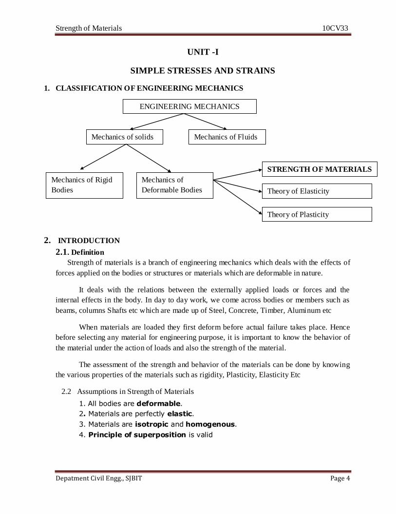
1. CLASSIFICATION OF ENGINEERING MECHANICS
2. INTRODUCTION
2.1 . Definition
Strength of materials is a branch of engineering mechanics which deals with the effects of
forces applied on the bodies or structures or materials which are deformable in nature.
It deals with the relations between the externally applied loads or forces and the
internal effects in the body. In day to day work, we come across bodies or members such as
beams, columns Shafts etc which are made up of Steel, Concrete, Timber, Aluminum etc
When materials are loaded they first deform before actual failure takes place. Hence
before selecting any material for engineering purpose, it is important to know the behavior of
the material under the action of loads and also the strength of the material.
The assessment of the strength and behavior of the materials can be done by knowing
the various properties of the materials such as rigidity, Plasticity, Elasticity Etc
2.2 Assumptions in Strength of Materials
1. All bodies are deformable.
2. Materials are perfectly elastic.
3. Materials are isotropic and homogenous.
4. Principle of superposition is valid
Mechanics of Fluids
ENGINEERING MECHANICS
Mechanics of solids
Mechanics of Rigid
Bodies
Mechanics of
Deformable Bodies
STRENGTH OF MATERIALS
Theory of Elasticity
Theory of Plasticity
Strength of Materials 10CV33
Depatment Civil Engg., SJBIT Page 5
5. St. Venant's Principle is valid. ("At points away from the loading points,
the behaviour of material will be independent of gripping forces or type of
application of load or local effects.")
2. SIMPLE STRESSES AND STRAINS
When a material is subjected to external forces or loads, it tends to deform. However
due to cohesion between the particles in the body, the material offers resistance to
deformation. (If the force is increased the resistance as well as the deformation also increases).
(The material will offer necessary resistance to deformation when the load is within a certain
limit). When material is not capable of offering necessary resistance against external forces,
permanent deformation will set in and failure of the member may occur, if the load is
increased.
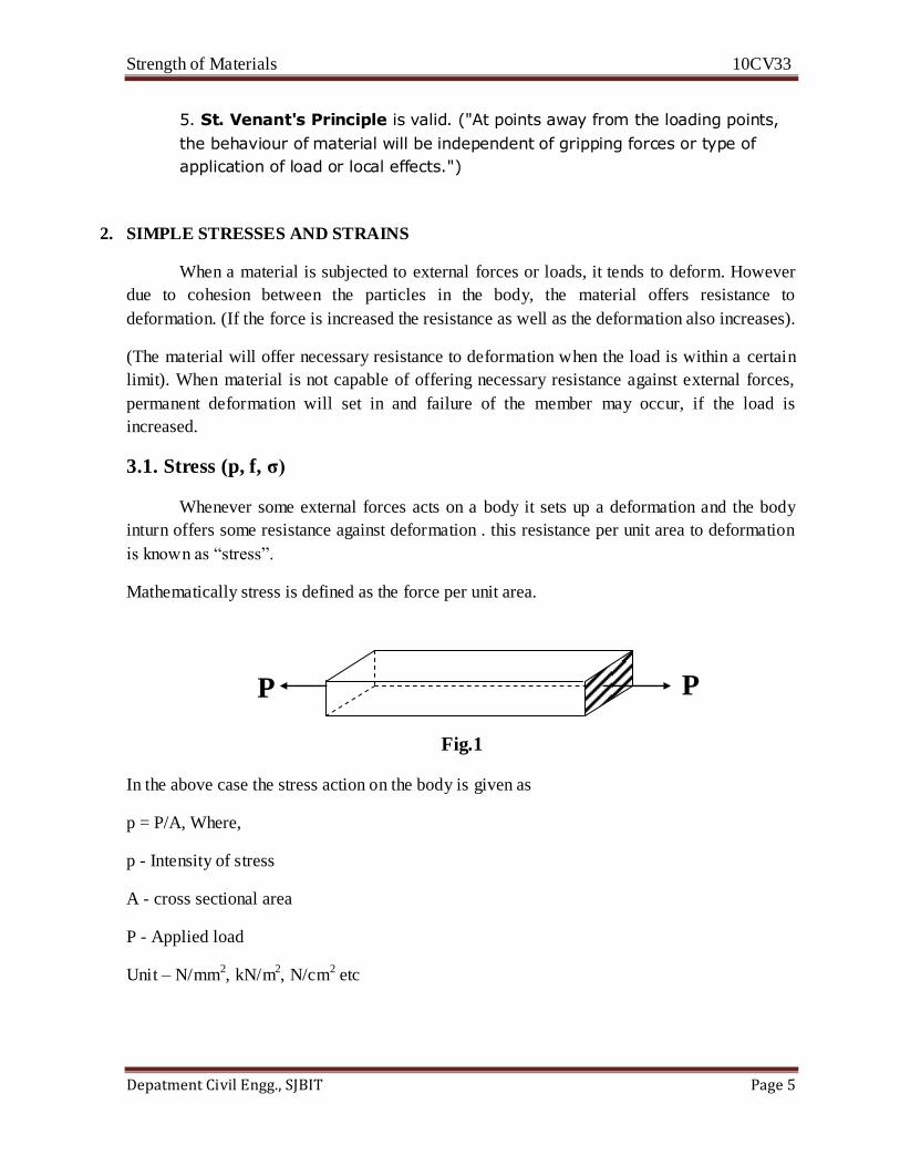
3.1. Stress (p, f, σ)
Whenever some external forces acts on a body it sets up a deformation and the body
inturn offers some resistance against deformation . this resistance per unit area to deformation
is known as “stress”.
Mathematically stress is defined as the force per unit area.
Fig.1
In the above case the stress action on the body is given as
p = P/A, Where,
p - Intensity of stress
A - cross sectional area
P - Applied load
Unit – N/mm2, kN/m2, N/cm2 etc
P P
Strength of Materials 10CV33
Depatment Civil Engg., SJBIT Page 6
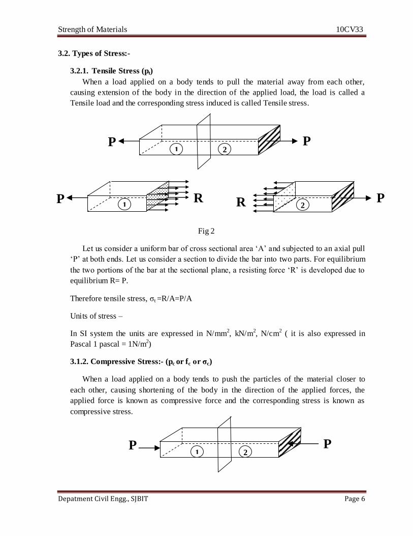
3.2. Types of Stress:-
3.2.1. Tensile Stress (pt)
When a load applied on a body tends to pull the material away from each other,
causing extension of the body in the direction of the applied load, the load is called a
Tensile load and the corresponding stress induced is called Tensile stress.
Fig 2
Let us consider a uniform bar of cross sectional area ‘A’ and subjected to an axial pull
‘P’ at both ends. Let us consider a section to divide the bar into two parts. For equilibrium
the two portions of the bar at the sectional plane, a resisting force ‘R’ is developed due to
equilibrium R= P.
Therefore tensile stress, σt =R/A=P/A
Units of stress –
In SI system the units are expressed in N/mm2, kN/m2, N/cm2 ( it is also expressed in
Pascal 1 pascal = 1N/m2)
3.1.2. Compressive Stress:- (pc or fc or σc)
When a load applied on a body tends to push the particles of the material closer to
each other, causing shortening of the body in the direction of the applied forces, the
applied force is known as compressive force and the corresponding stress is known as
compressive stress.
1 2 P P
1 P R
2 P R
1 2 P P

Strength of Materials 10CV33
Depatment Civil Engg., SJBIT Page 7
Fig-3
The compressive stress at any section along the length of the load is given as
σc =
σc =
=
Units – N/mm2, kN/m2, N/cm2 etc
3.1.3. Shear stress:- (τ or q)
When a load applied on a body causes one portion of the body to slide over the
adjoining portion, such a force is known as Shear Force and the corresponding stress is
known as Shear Stress.
Fig-4
As shown in the fig, the body might separate into two portions causing one portion to
slide over the another. At the plane of separation a resisting force ‘R’ is developed. Thus
shear stress is given as
1 P R
2
P R
1
2
P
P
1
P
R
2
P
R
Strength of Materials 10CV33
Depatment Civil Engg., SJBIT Page 8
τ =
τ =
=
In the above, Tensile stresses and compressive stresses are known as Direct stresses.
Whereas Shear stresses is known as Tangential stresses.
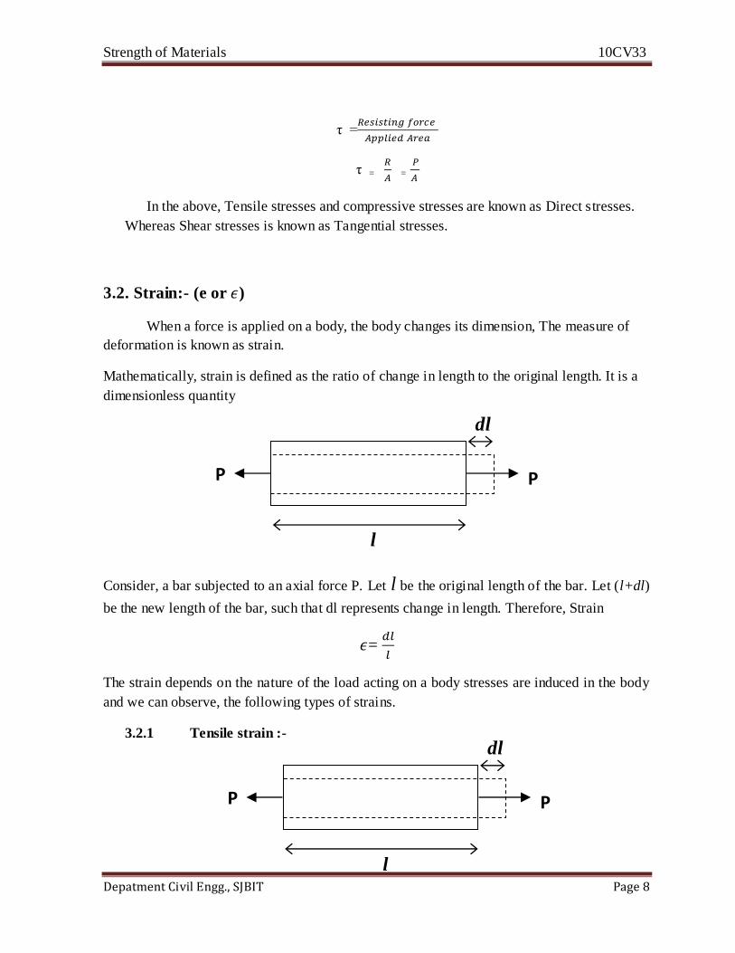
3.2. Strain:- (e or )
When a force is applied on a body, the body changes its dimension, The measure of
deformation is known as strain.
Mathematically, strain is defined as the ratio of change in length to the original length. It is a
dimensionless quantity
Consider, a bar subjected to an axial force P. Let l be the original length of the bar. Let (l+dl)
be the new length of the bar, such that dl represents change in length. Therefore, Strain
=
The strain depends on the nature of the load acting on a body stresses are induced in the body
and we can observe, the following types of strains.
3.2.1 Tensile strain :-
P P
dl
l
P P
dl
l

Strength of Materials 10CV33
Depatment Civil Engg., SJBIT Page 9
When a tensile force acts on a body, it elongates in the direction of force P by an amount
of dl and then the strain is called Tensile Strain.
Thus, tensile strain is given as
=
3.2.2. Compressive strain:
When an axial compressive force acts on a body causing shortening of the body by an
amount ‘dl’ in the direction of the applied force, the strain observed is called compressive
strain and it is given as
=
3.2.3. Shear strain :-
Fig
Consider an element of unit thickness subjected to a shear force as shown in fig. The body
deforms as shown (Point D shifts to D' and Point C shifts to C')
Let Φ represent the angular rotation of the vertical faces. Let dl represent the horizontal on
transverse displacement of the upper face with respect to the lower face. This
displacement occurs over a length ‘l’. In such a case shear strain is defined as,
Shear Strain =
l
P
P
D C
B A
D’
C’
P
dl
l
Strength of Materials 10CV33
Depatment Civil Engg., SJBIT Page 10
From the triangle ADD’, tan =
For very small values of Φ we have tan =
=
This implies that, shear strain can be measures directly by measuring the angular rotation Φ
(Φ is measured in radians)
4. Elasticity
When an external force acts on a body, the body tends to deform and deformation continues
till full resistance to external forces is set up. Once the load causing deformation is removed, the
body returns to its original shape. This property by virtue of which a body regains its original
shape after the external forces are removed is called Elasticity.
A material is said to be perfectly elastic if it regains its original shape completely.
Steel, Copper, Aluminum, Brass, Concrete and wood are considered to be perfectly elastic
within certain limits.
Note:-
1. A homogeneous material is one which is made up of same kind if material
throughout.
2. An isotropic material is one which has the same elastic properties in all direction.
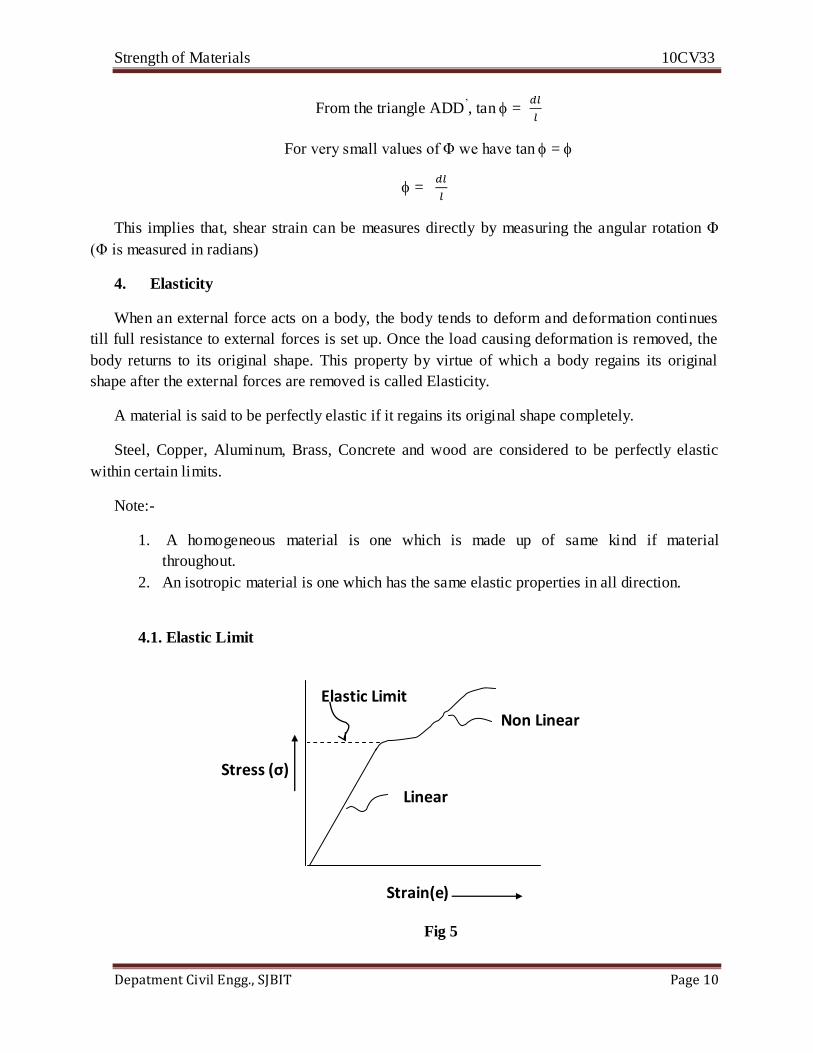
4.1. Elastic Limit
Fig 5
Strain(e)
Stress (σ)
Linear
Elastic Limit
Non Linear
Strength of Materials 10CV33
Depatment Civil Engg., SJBIT Page 11
When any material is loaded or stressed, it deforms, when the load is removed, the body
regains its original shape. However if the stress is increased beyond a certain value or limit, the
material fails to regain its original shape even when the load is removed. This limiting stress upto
which the material behaves as an elastic material is called elastic limit.
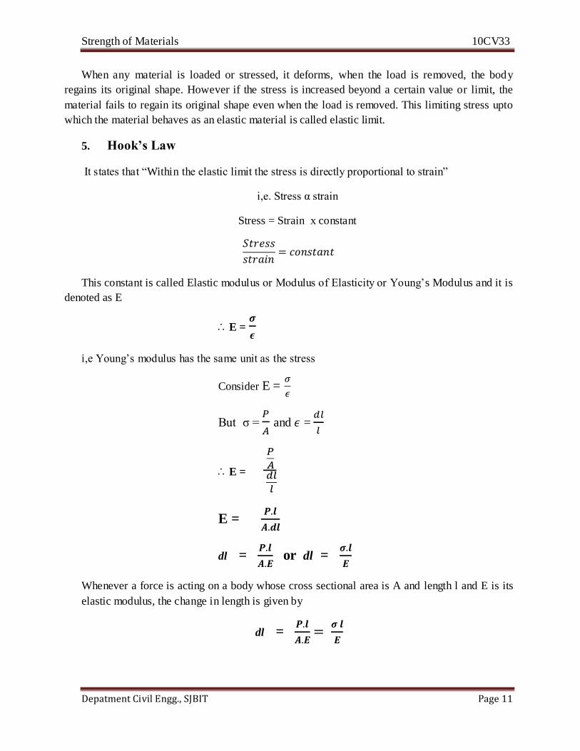
5. Hook’s Law
It states that “Within the elastic limit the stress is directly proportional to strain”
i,e. Stress α strain
Stress = Strain x constant
This constant is called Elastic modulus or Modulus of Elasticity or Young’s Modulus and it is
denoted as E
E =
i,e Young’s modulus has the same unit as the stress
Consider E =
But σ =
and =
E =
E =
dl =
or dl =
Whenever a force is acting on a body whose cross sectional area is A and length l and E is its
elastic modulus, the change in length is given by
dl =
Strength of Materials 10CV33
Depatment Civil Engg., SJBIT Page 12
Values of Young’s modulus E for different materials
Material Value of E
1) Steel 210 x 103 N/mm
2
2) Wrought Iron 190 x 103 N/mm
2
3) Cast Iron 120 x 103 N/mm
2
4) Copper 90 x 103 N/mm
2
5) Brass 80 x 103 N/mm
2
6) Aluminum 70 x 103 N/mm
2
7) Wood 10 x 103 N/mm
2
6. Principle of superposition
When a number of loads are acting on a body the resulting strain according to principle of
superposition will be “The algebraic sum of the strains caused by the individual forces”
If an elastic body is subjected to a number of direct forces (tensile or compressive) at different
sections along the length of the body , deformations the individual sections can be calculated
if the free body diagrams of the individual sections are considered separately. The net (total)
deformation is sum of the individual deformations.
7. Mechanical properties of materials
The following are considered as the most important properties of engineering materials
1) Elasticity
2) Plasticity
3) Ductility
4) Malleability
5) Brittleness
6) Toughness
7) Hardness
Any material cannot posses all the above properties because the different properties oppose
each oter. Hence the engineering Materials can be classified as follows depending upon their
Mechanical properties
a) Elastic Materials:- These are materials which undergo deformation due to application
of forces and once the forces are removed the material regains its original shape.
b) Plastic materials :- These are materials which do not regain their original slope even
after the external loads acting on the mare removed
Strength of Materials 10CV33
Depatment Civil Engg., SJBIT Page 13
c) Ductility :- these are material that can undergo considerable deformation without much
increase in he load od\r in simple terms, these are materials that can be drawn into
wires
d) Malleable materials:- These are Materials which can be extended in two directions
easily or in simple terms, materials which can be beaten into thin sheets.
e) E) Brittle materials:- these are materials which do not undergo any deformation before
failure when external forces act on them.
f) Tough materials :- These are materials which can resist sudden loads or shock loads
without showing any fracture on failure
g) Hard material:- These are materials that have the ability to resist surface abrasion or
indentation (Markings)
Various tests are carried out on engineering materials to assess their mechanical properties
in a material testing laboratory. They are
1) Tension test
2) Compression test
3) Impact test
4) Shear test
5) Torsion test
6) Bending test
7) Fatigue test
8) Hardness test
8. St Venant’s Principle:-
It states that, “In a bar carrying direct or normal loads, except in the extreme end regions
of the bar, the stress distribution over the cross section is uniform”.
If we consider a bar of uniform cross section (b x b) and subjected to direct axial load P,
we can consider three different sections at different distances from the extreme as in fig.
The stress distribution at different distances is different and is represented in each case as
shown above.
We see that the stress distribution is uniform at section like 3. This stress distribution is
possible if the load P acts through the centroid of the cross section or axially.
9. Tension Test on Mild Steel specimen:-
A typical tensile test specimen on mild steel is as shown above. The ends of the specimen
are gripped into a universal testing machine.
Strength of Materials 10CV33
Depatment Civil Engg., SJBIT Page 14
The specimen has lager diameter at the ends to see that the specimen at the ends to see that
the specimen does not fail in the end regions. The specimen should fail in the gauged
portion. The deformation is recorded as the load is applied(increases).
The elongation is recorded with the help of strain gauges. The loading is done till the
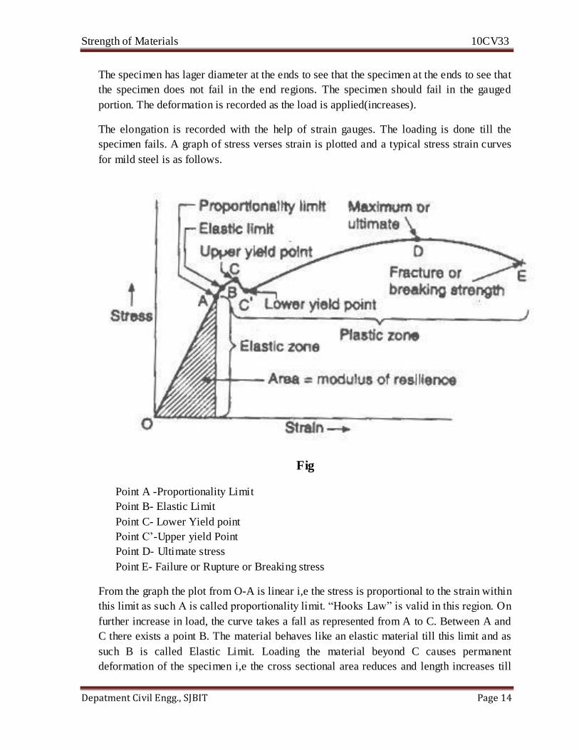
specimen fails. A graph of stress verses strain is plotted and a typical stress strain curves
for mild steel is as follows.
Fig
Point A -Proportionality Limit
Point B- Elastic Limit
Point C- Lower Yield point
Point C’-Upper yield Point
Point D- Ultimate stress
Point E- Failure or Rupture or Breaking stress
From the graph the plot from O-A is linear i,e the stress is proportional to the strain within
this limit as such A is called proportionality limit. “Hooks Law” is valid in this region. On
further increase in load, the curve takes a fall as represented from A to C. Between A and
C there exists a point B. The material behaves like an elastic material till this limit and as
such B is called Elastic Limit. Loading the material beyond C causes permanent
deformation of the specimen i,e the cross sectional area reduces and length increases till
Strength of Materials 10CV33
Depatment Civil Engg., SJBIT Page 15
the upper yield point C is reached. Loading the specimen beyond C, the material regains
some strength and this continues till ultimate stress (D) is reached. On further increase in
load the specimen finally fails at failure stress(E).
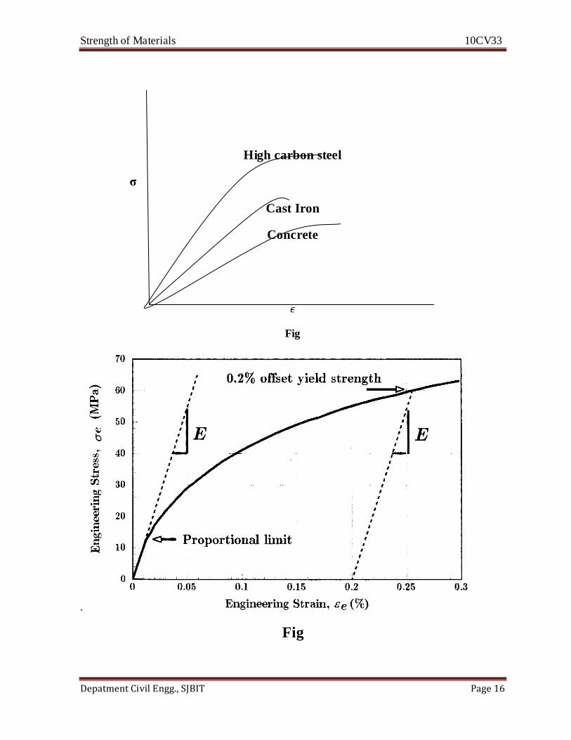
1) Proportional Limit / Limit of proportionality :-
It is the limiting or maximum stress value upto which the stress is proportional to the
strain.
2) Elastic Limit :-This is the maximum or limiting stress value such that there is mo
permanent deformation in the material.
3) Yield Point /Yield Strength:- These are the lower stresses at which the extension of the
specimen is rapid without much increase in the strain.
4) Ultimate stress or yield strength:- this is the maximum stress, the material can resist.
5) Breaking stress/ Breaking strength:- this is stress at which the specimen fails or breaks
or ruptures.
9.1 Working stress and factor safety :-
In designing any engineering components stressing the material upto its ultimate strength
is not advisable for following reasons
1) Stressing the material till ultimate strength causes the deformation or the failure of the
member.
2) The material may not be 100% reliable.
3) The material may contain minor defects.
Hence the material is stressed to a point much lesser than ultimate strength. Such a stress is
called working stress which is normally equal to stress at proportional limit.
The ratio of the ultimate stress to the working stress is known as “Factor of Safety”
Different materials have different strength and also different reliability and hence the factor of
safety for these materials will also vary and there are presented in the tabular column
Material Steel Concrete Timber
Factor of safety 1.85 3 4to 6
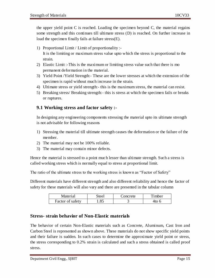
Stress- strain behavior of Non-Elastic materials
The behavior of certain Non-Elastic materials such as Concrete, Aluminum, Cast Iron and
Carbon Steel is represented as shown above. These materials do not show specific yield points
and their failure is sudden. In such cases to determine the approximate yield point or stress,
the stress corresponding to 0.2% strain is calculated and such a stress obtained is called proof
stress.
Strength of Materials 10CV33
Depatment Civil Engg., SJBIT Page 16
High carbon steel
σ
Cast Iron
Concrete
Fig
.
Fig
Strength of Materials 10CV33
Depatment Civil Engg., SJBIT Page 17
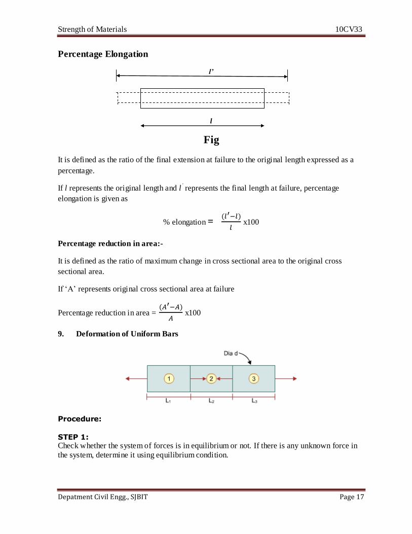
Percentage Elongation
l’
l
Fig
It is defined as the ratio of the final extension at failure to the original length expressed as a
percentage.
If l represents the original length and l’ represents the final length at failure, percentage
elongation is given as
% elongation =
x100
Percentage reduction in area:-
It is defined as the ratio of maximum change in cross sectional area to the original cross
sectional area.
If ‘A’ represents original cross sectional area at failure
Percentage reduction in area =
x100
9. Deformation of Uniform Bars
Procedure:
STEP 1: Check whether the system of forces is in equilibrium or not. If there is any unknown force in
the system, determine it using equilibrium condition.

Strength of Materials 10CV33
Depatment Civil Engg., SJBIT Page 18
STEP 2: Separate each part and find the force acting on each part.
STEP 3:
The total deformation is given by the algebraic sum of deformation of each part.
Deformation of Varying Cross section Bars
Procedure:
STEP 1: Check whether the system of forces is in equilibrium or not. If there is any unknown force, determine it using equilibrium condition.
STEP 2: Separate each part and find the force acting on each part.
STEP 3:
The total deformation is given by the algebraic sum of deformation of each part.
If the Young’s Modulus of the material is different, then the change in length is given by
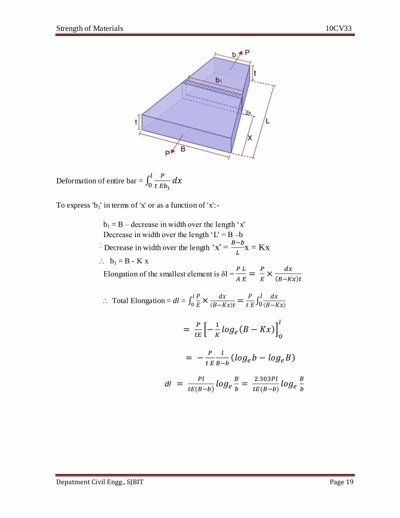
Deformation of Tapering Bars of Uniform Thickness
Let us consider a tapering bar of const thickness 't' and width varying from 'B' to 'b' over a
length 'L' subjected to direct load 'P'. Let us consider an elemental strip of length 'dx' at a
distance 'x' as shown in fig. The elemental strip can be considered to be uniform.
We have deformation of elemental strip =
Strength of Materials 10CV33
Depatment Civil Engg., SJBIT Page 19
Deformation of entire bar =
To express 'b1' in terms of 'x' or as a function of 'x':-
b1 = B – decrease in width over the length ‘x'
Decrease in width over the length ‘L' = B –b
Decrease in width over the length ‘x' =
x = Kx
b1 = B - K x
Elongation of the smallest element is δl =
Total Elongation = dl =
dl

Strength of Materials 10CV33
Depatment Civil Engg., SJBIT Page 20
Deformation due to Self Weight
When a bar is suspended at its top, it will undergo tensile deformation due to self weight. The
top most section is subjected to maximum force equal to the total weight of the bar and
bottom most section is subjected to no force due to self weight.
When a bar is supported at its bottom, it will undergo compressive deformation due to self
weight. In this case bottom most section is subjected to maximum load due to self weight and
top most section is subjected to no force due to self weight.
Note:
Specified weight or weight density of a material is the weight per unit volume of the material.
N/mm2
i.e. W = X V
Let us consider uniform bar or area of cross section 'A' and length 'L' supported as shown in
figure. Let us consider an elemental strip of length 'dy' at a distance 'y' as shown in figure.
Force on elemental strip = weight of material below the elemental strip.

Strength of Materials 10CV33
Depatment Civil Engg., SJBIT Page 21
If an external load 'W' is applied on the uniform bar, then its deformation will be =
Therefore deformation due to self weight of uniform bar is equal to one-half the deformation
of the same bar under an external load equal to the total weight of the bar
Problems:
1. A mild steel rod 2.5 m long having a cross sectional area of 50 mm2 is subjected
to a tensile force of 1.5 kN. Determine the stress, strain, and the elongation of the
rod. Take E = 2 × 10⁵ N/mm2
Solution:
Data Given
Length of the rod ‘L’ = 2.5 m = 250 mm
Area of cross-section ‘A’ = 50 mm2
Tensile force ‘P’ = 1.5 kN = 1.5 × 10³ N
Young’s Modulus ‘E’ = 2 × 10⁵ N/mm2

Strength of Materials 10CV33
Depatment Civil Engg., SJBIT Page 22
Stress σ = P/A= 1.5×10³ / 50 =30N /mm2
Since, E = Stress / Strain Strain = Stress / E = 30 / 2 × 105 = 0.0015
Also, Elongation = Strain x Original length = 0.0015 × 2500 = 0.375 mm.
2. A load of 100 kN is to be lifted with the help of a steel wire of 5 m length. The
permissible limit of stress for wire is 150 N/mm2. Find the minimum diameter of
the steel wire and the elongation at the permissible limit. Take E = 2 X 10⁵
N/mm2
Solution:
Given Data
Tensile load ‘P’ = 100 kN
Length of wire ‘L’ = 5 m = 5000 mm
Stress ‘σ’ = 150 N/mm2
E = 2 × 10⁵ N/mm2
d = 29.13 mm
δL = (100 × 103) × 5000 / 666.67 × 2 × 105 = 3.75 mm.
3.A steel bar AB of uniform thickness 2 cm, tapers uniformly from 15 cm to 7.5 cm in
a length of 50 cm. Determine the elongation of the plate; if an axial tensile force of
100 kN is applied on it and E = 2 × 10¹¹
N/m2.
Solution: 100kN
100kN 7.5cm 15cm
dl =
Strength of Materials 10CV33
Depatment Civil Engg., SJBIT Page 23
Unit 2
COMPOSITE SECTION
A section made up of more than one material designed to resist the applied load is called
'COMPOSITE SECTION'.
In a composite section, materials are placed in parallel and under the load the section behaves
like a single material. Under the load, there will not be separation of materials. Materials of
composite sections undergo equal amount of deformation under load.
Ex: A section of Reinforced Cement Concrete - it is made up of 2 materials namely,
Concrete and Steel.
1. Total load applied on the composite section is shared among different materials of
composite section, i.e., P = P1 +P2 + P3 + .........
2. Different materials of composite section should undergo equal amount of deformation
i.e., L1 = L2 = L3 = .............
3. The material can also have same strain if the materials are of same length
Modular ratio: Modular ratio between two materials is defined as the ratio of Young's
Modulus of Elasticity of two materials.
Eg: Modular ratio between steel and concrete is 15, i.e., Es / Ec = 15
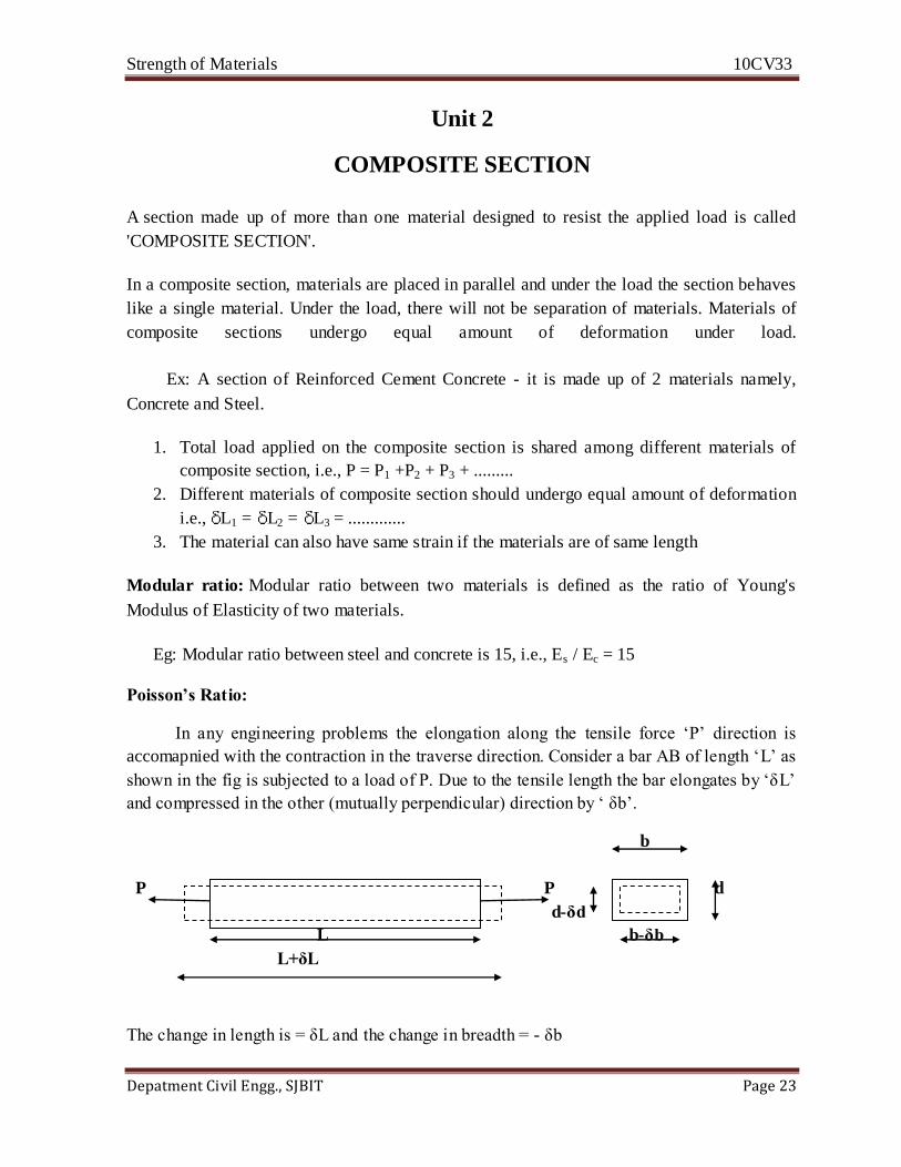
Poisson’s Ratio:
In any engineering problems the elongation along the tensile force ‘P’ direction is
accomapnied with the contraction in the traverse direction. Consider a bar AB of length ‘L’ as
shown in the fig is subjected to a load of P. Due to the tensile length the bar elongates by ‘δL’
and compressed in the other (mutually perpendicular) direction by ‘ δb’.
b
P P d
d-δd
L b-δb
L+δL
The change in length is = δL and the change in breadth = - δb
Strength of Materials 10CV33
Depatment Civil Engg., SJBIT Page 24
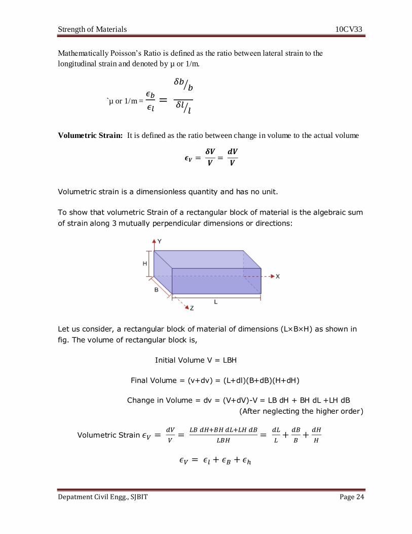
Mathematically Poisson’s Ratio is defined as the ratio between lateral strain to the
longitudinal strain and denoted by µ or 1/m.
`µ or 1/m =
Volumetric Strain: It is defined as the ratio between change in volume to the actual volume
Volumetric strain is a dimensionless quantity and has no unit.
To show that volumetric Strain of a rectangular block of material is the algebraic sum
of strain along 3 mutually perpendicular dimensions or directions:
Let us consider, a rectangular block of material of dimensions (L×B×H) as shown in
fig. The volume of rectangular block is,
Initial Volume V = LBH
Final Volume = (v+dv) = (L+dl)(B+dB)(H+dH)
Change in Volume = dv = (V+dV)-V = LB dH + BH dL +LH dB
(After neglecting the higher order)
Volumetric Strain
Strength of Materials 10CV33
Depatment Civil Engg., SJBIT Page 25
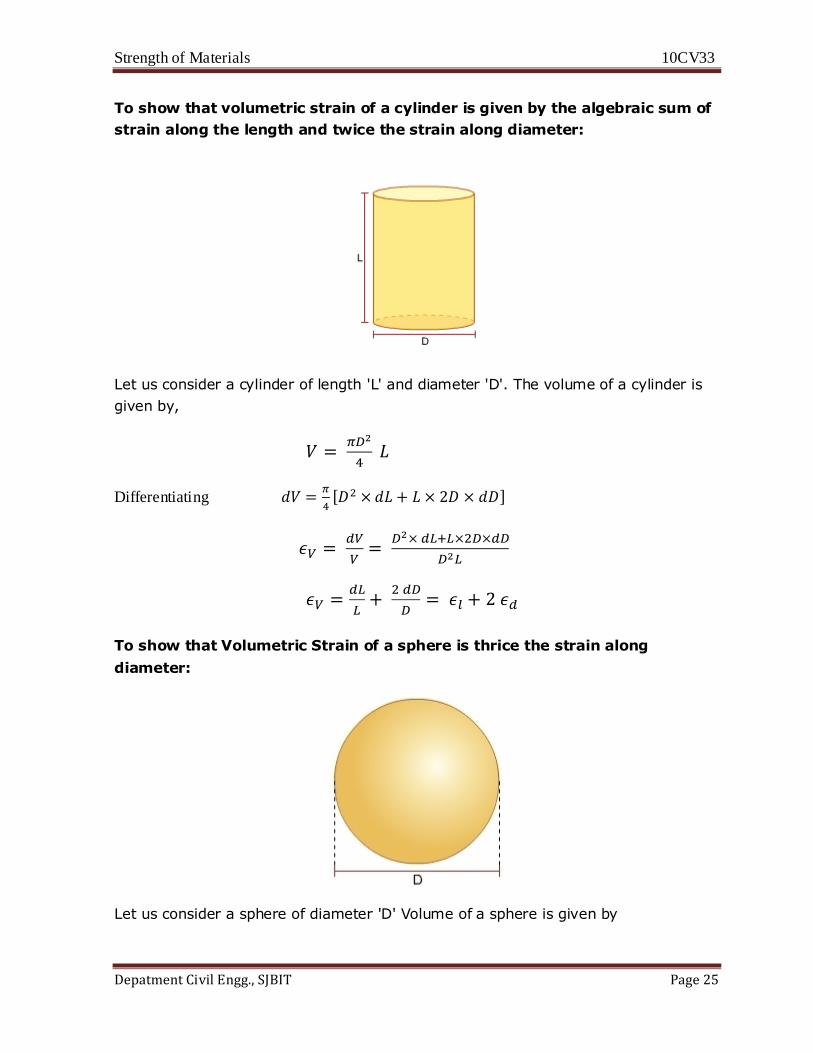
To show that volumetric strain of a cylinder is given by the algebraic sum of
strain along the length and twice the strain along diameter:
Let us consider a cylinder of length 'L' and diameter 'D'. The volume of a cylinder is
given by,
Differentiating
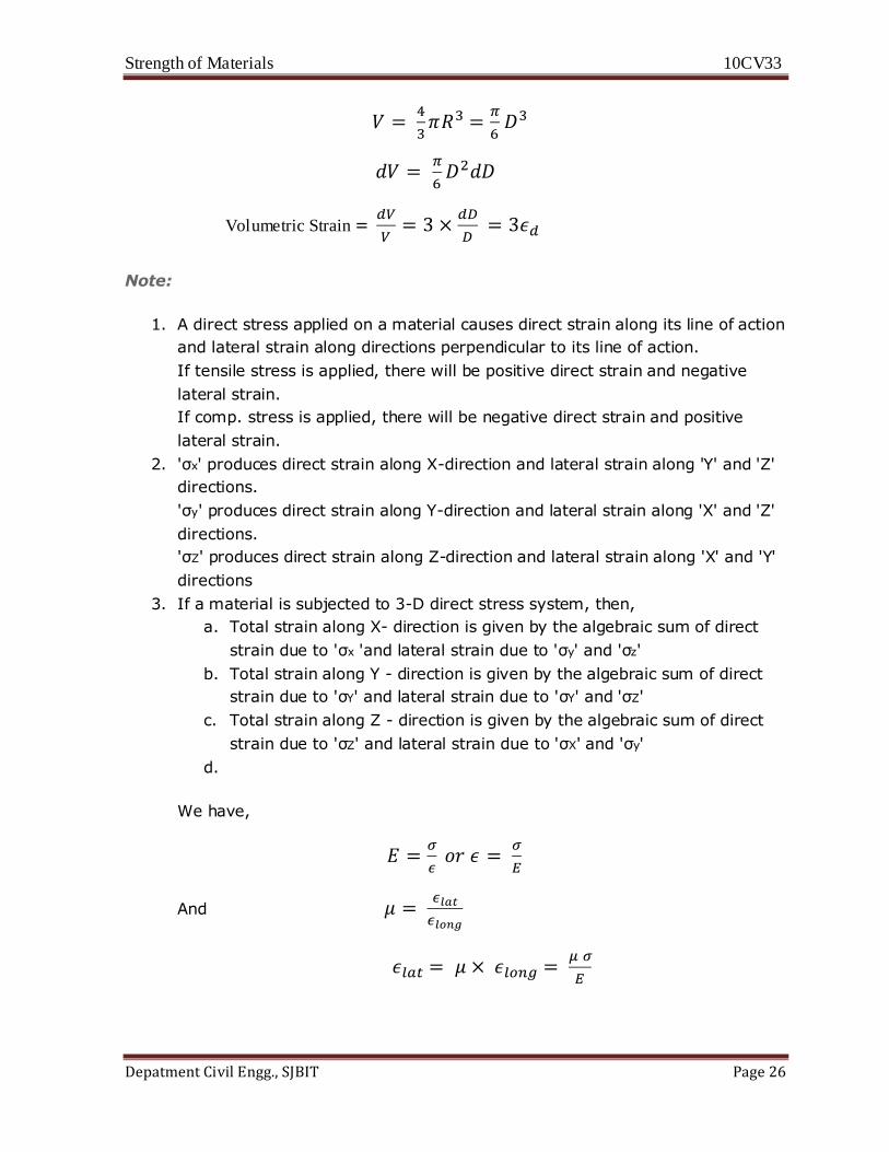
To show that Volumetric Strain of a sphere is thrice the strain along
diameter:
Let us consider a sphere of diameter 'D' Volume of a sphere is given by
Strength of Materials 10CV33
Depatment Civil Engg., SJBIT Page 26
Volumetric Strain =
Note:
1. A direct stress applied on a material causes direct strain along its line of action
and lateral strain along directions perpendicular to its line of action.
If tensile stress is applied, there will be positive direct strain and negative
lateral strain.
If comp. stress is applied, there will be negative direct strain and positive
lateral strain.
2. 'σx' produces direct strain along X-direction and lateral strain along 'Y' and 'Z'
directions.
'σy' produces direct strain along Y-direction and lateral strain along 'X' and 'Z'
directions.
'σZ' produces direct strain along Z-direction and lateral strain along 'X' and 'Y'
directions
3. If a material is subjected to 3-D direct stress system, then,
a. Total strain along X- direction is given by the algebraic sum of direct
strain due to 'σx 'and lateral strain due to 'σy' and 'σz'
b. Total strain along Y - direction is given by the algebraic sum of direct
strain due to 'σY' and lateral strain due to 'σY' and 'σZ'
c. Total strain along Z - direction is given by the algebraic sum of direct
strain due to 'σZ' and lateral strain due to 'σX' and 'σy'
d.
We have,
And

Strength of Materials 10CV33
Depatment Civil Engg., SJBIT Page 27
σz σy
σx σx
σy
σz
------- (1)
------- (2)
-------(3)
Equations (1), (2) and (3) relate 3 - dimensional stresses and corresponding strains. They are
called 'Generalized Hook's Law Statements'
Thermal Stress
When a body is subjected to change in temperature its dimensions will also be changed (since
the bodies are subjected to thermal expansion or contraction). For metals when the
temperature of a body is increased there is a corresponding increase in its dimensions.
When the body is allowed to expand (without restraining) no stress develops. But, in case the
body is restrained prevents the expansion, then the stresses in the body will develop. These
stresses are called as thermal stress. It may be tensile or compressive depending upon whether
the contraction is prevented or extension is prevented.
Mathematically it is defined as , let us consider a bar of length L placed between two supports
to prevent the extension in its length. If the temperature of bar is increased through Δ t°C, the
bar will be increased in length by an amount
Stress Direct Stress Lateral Strain
σx +
σy +
σz +
Strength of Materials 10CV33
Depatment Civil Engg., SJBIT Page 28
ΔL = L.α.Δt
Where α is the coefficient of thermal expansion.
The thermal stress is = σt = E = E L t/L = E t
Note: If the supports used to prevent the expansion yield by an amount δ, the total
amount prevented will become (ΔL –δ).
The thermal stress is = σt = E = E (L- δ) t/L
Problems:
1. The principal stresses at a point in an elastic material are 70 N/mm
2 tensile, 30 N/mm
2
tensile, and 50 N/mm2
compressive.
Calculate the volumetric strain. Given E = 2 × 10¹¹
N/m2; µ = 0.30
Solution:
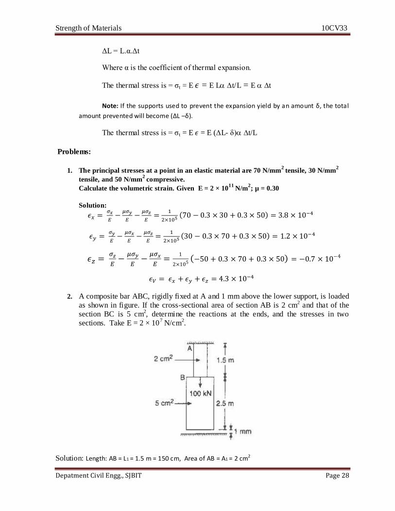
2. A composite bar ABC, rigidly fixed at A and 1 mm above the lower support, is loaded
as shown in figure. If the cross-sectional area of section AB is 2 cm2 and that of the
section BC is 5 cm2, determine the reactions at the ends, and the stresses in two
sections. Take E = 2 × 10⁷ N/cm2.
Solution: Length: AB = L1 = 1.5 m = 150 cm, Area of AB = A1 = 2 cm2

Strength of Materials 10CV33
Depatment Civil Engg., SJBIT Page 29
Length: BC = L2 = 2.5 m = 250 cm, Area of BC = A2 = 5 cm2 Distance between C and lower support = 0.1 cm
Load on the bar ‘P’ = 100 kN, Young’s modulus= E = 2 × 10⁷ N/cm2
Assume that, reaction at end A = RA, Reaction at end C = RC It is notable that the bar is rigidly
fixed at A and loaded at B, not at C. Thus, only AB is under tension while BC under no stress until C touches the rigid support
Let δL = Increase in length of AB when subjected to a load to 100 kN. From fundamentals δL = PL/AE
δL =
Since, the increase in length AB is more than 0.1 cm therefore some part of load will be
required to increase AB by 0.1 cm and remaining will be shared by the portions AB and BC of the bar.
Thus using; δL = PL / AE
0.1 = P1 × 150 / 2.0 × 2 × 107 P1 = 26.67 kN ⇒ P – P1 = P2 = 73.33 kN
The load P2 will be shared by AB and BC. Let the reaction at A (beyond 0.1 cm) = RA1 And the
reaction at C (beyond 0.1 cm) = RC
RA1 + RC = 73.33 kN ………..…(1)
Let δL1 = Increase in length of AB (beyond 0.1 cm)
δL2 = Decrease in length of BC (beyond 0.1 cm)
δL1 =
and δL2 =
δL1 = δL2
RA1 = 2/3 Rc
RC = 44 kN and RA1 = 29.33 kN
Total reaction at A = 26.67 + 29.3 = 56 kN and total reaction at B = 44 kN Therefore,
stresses in two sections are σAB = RA/A1 = 56 X 103/2 = 28kN/cm2
σBC = Rc/A2 = 44 X 103/5 = 8.8kN/cm2
Strength of Materials 10CV33
Depatment Civil Engg., SJBIT Page 30
Unit 3
Compound Stresses:
GENERAL
Structural members are subjected to various kinds of loads. This results in combination of
different stresses which changes from point to point. When an element (considered at any
point) in a body is subjected to a combination of normal stresses (tensile and/or compressive)
and shear stresses over its various planes, the stress system is known as compound stress
system. In a compound stress system, the magnitude of normal stress may be maximum on
some plane and minimum on some plane, when compared with those acting on the element.
Similarly, the magnitude of shear stresses may also be maximum on two planes when
compared with those acting on the element. Hence, for the considered compound stress
system it is important to find the magnitudes of maximum and minimum normal stresses,
maximum shear stresses and the inclination of planes on which they act.
PLANE STRESS OR 2–D STRESS SYSTEM OR BIAXIAL STRESS SYSTEM
Generally a body is subjected to 3–D state of stress system with both normal and shear
stresses acting in all the three directions. However, for convenience, in most problems,
variation of stresses along a particular direction can be neglected and the remaining stresses
are assumed to act in a plane. Such a system is called 2–D stress system and the body is called
plane stress body.
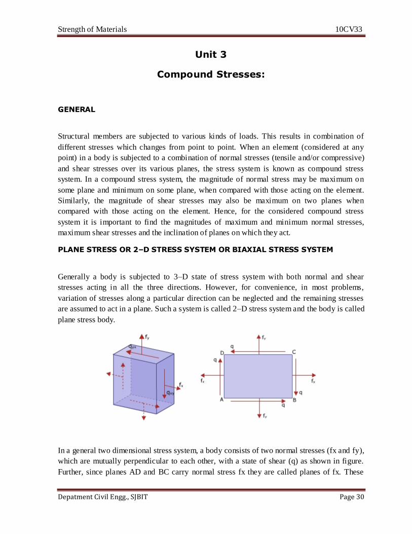
In a general two dimensional stress system, a body consists of two normal stresses (fx and fy),
which are mutually perpendicular to each other, with a state of shear (q) as shown in figure.
Further, since planes AD and BC carry normal stress fx they are called planes of fx. These
Strength of Materials 10CV33
Depatment Civil Engg., SJBIT Page 31
planes are parallel to Y–axis. Similarly, planes AB and CD represent planes of fy, which are
parallel to X–axis.
PRINCIPAL STRESSES AND PRINCIPAL PLANES
For a given compound stress system, there exists a maximum normal stress and a minimum
normal stress which are called the Principal stresses. The planes on which these Principal
stresses act are called Principal planes. In a general 2-D stress system, there are two Principal
planes which are always mutually perpendicular to each other. Principal planes are free from
shear stresses. In other words Principal planes carry only normal stresses.
MAXIMUM SHEAR STRESSES AND ITS PLANES
For a given 2–D stress system, there will be two maximum shear stresses (of equal
magnitude) which act on two planes. These planes are called planes of maximum shear. These
planes are mutually perpendicular. Further, these planes may or may not carry normal stress.
The planes of maximum shear are always inclined at 450 with Principal planes.
EXPRESSIONS FOR NORMAL AND TANGENTIAL COMPONENTS OF STRESS ON
A GIVEN PLANE
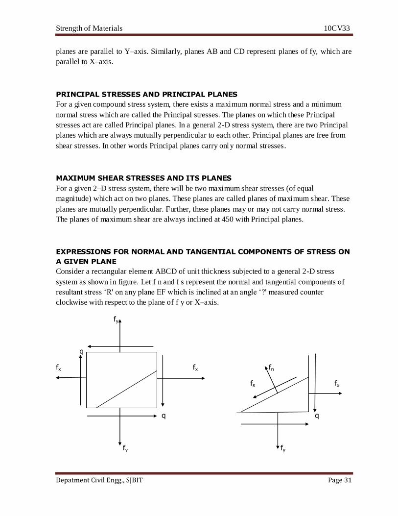
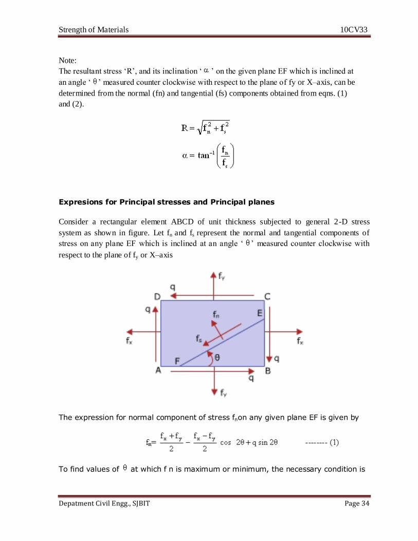
Consider a rectangular element ABCD of unit thickness subjected to a general 2-D stress
system as shown in figure. Let f n and f s represent the normal and tangential components of
resultant stress ‘R' on any plane EF which is inclined at an angle ‘?' measured counter
clockwise with respect to the plane of f y or X–axis.
fy
q
fx fx fn
fs fx
q q
fy fy
Strength of Materials 10CV33
Depatment Civil Engg., SJBIT Page 32
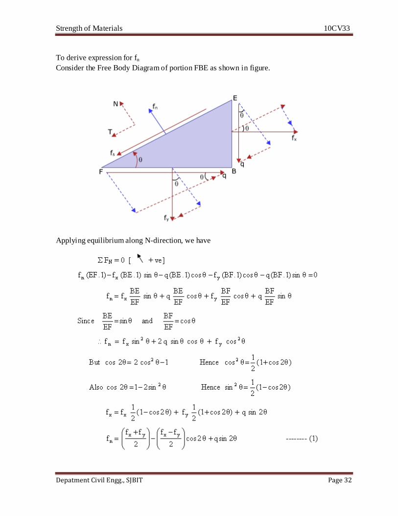
To derive expression for fn
Consider the Free Body Diagram of portion FBE as shown in figure.
Applying equilibrium along N-direction, we have
Strength of Materials 10CV33
Depatment Civil Engg., SJBIT Page 33
Equation (1) is the desired expression for normal component of stress on a given plane,
inclined at an angle ‘ ' measured counter clockwise with respect to the plane of fY or X–
axis
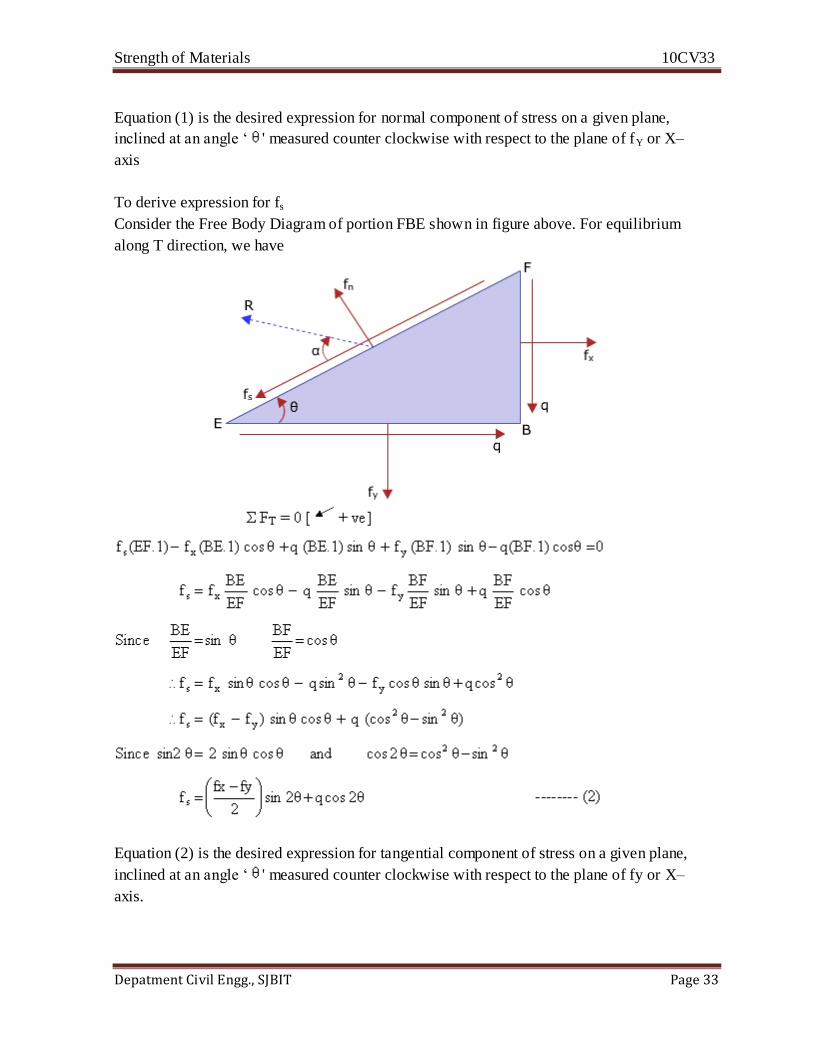
To derive expression for fs
Consider the Free Body Diagram of portion FBE shown in figure above. For equilibrium
along T direction, we have
Equation (2) is the desired expression for tangential component of stress on a given plane,
inclined at an angle ‘ ' measured counter clockwise with respect to the plane of fy or X–
axis.
Strength of Materials 10CV33
Depatment Civil Engg., SJBIT Page 34
Note:
The resultant stress ‘R’, and its inclination ‘ ’ on the given plane EF which is inclined at
an angle ‘ ’ measured counter clockwise with respect to the plane of fy or X–axis, can be
determined from the normal (fn) and tangential (fs) components obtained from eqns. (1)
and (2).
Expresions for Principal stresses and Principal planes
Consider a rectangular element ABCD of unit thickness subjected to general 2-D stress
system as shown in figure. Let fn and fs represent the normal and tangential components of
stress on any plane EF which is inclined at an angle ‘ ’ measured counter clockwise with
respect to the plane of fy or X–axis
The expression for normal component of stress fnon any given plane EF is given by
To find values of at which f n is maximum or minimum, the necessary condition is
Strength of Materials 10CV33
Depatment Civil Engg., SJBIT Page 35
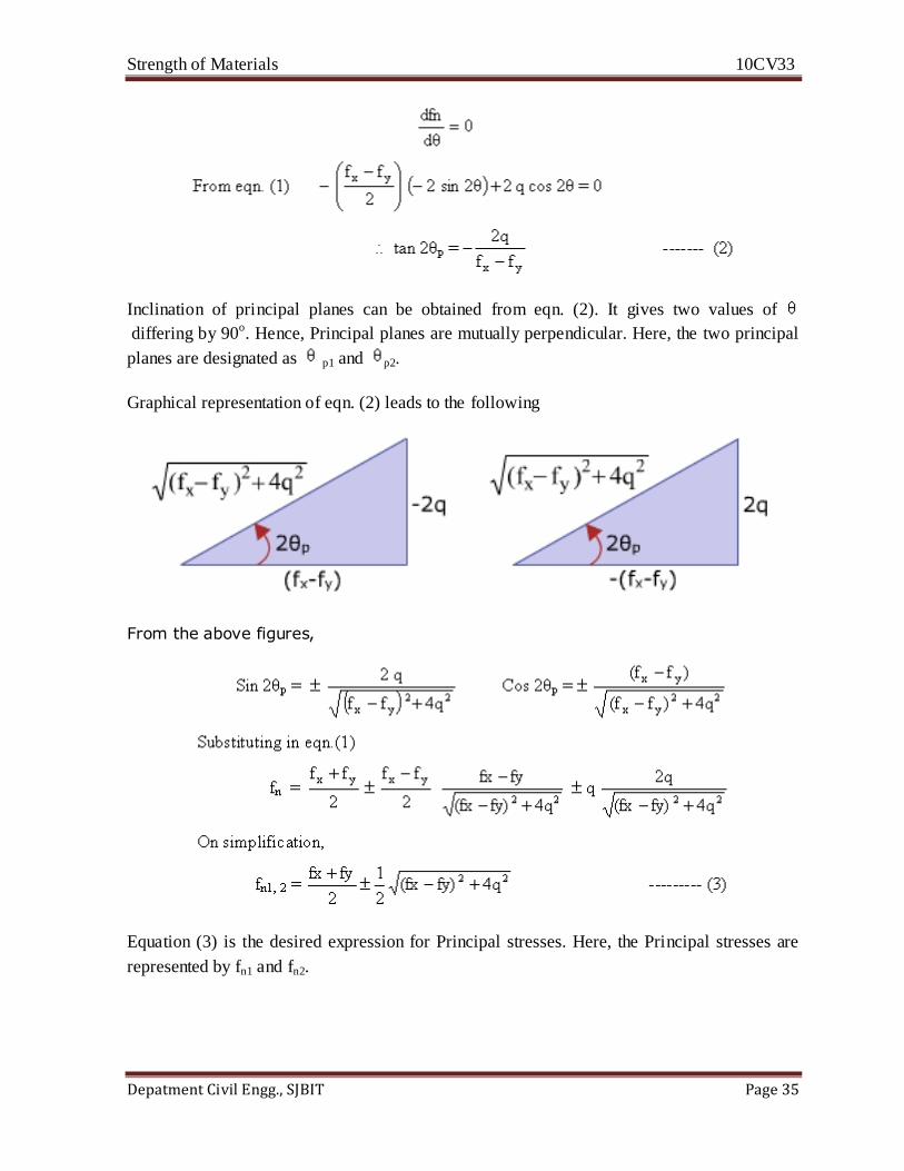
Inclination of principal planes can be obtained from eqn. (2). It gives two values of
differing by 90o. Hence, Principal planes are mutually perpendicular. Here, the two principal
planes are designated as p1 and p2.
Graphical representation of eqn. (2) leads to the following
From the above figures,
Equation (3) is the desired expression for Principal stresses. Here, the Principal stresses are
represented by fn1 and fn2.
Strength of Materials 10CV33
Depatment Civil Engg., SJBIT Page 36
Mohr’s Circle
The formulae developed so far (to find fn, fs, fn-max , fn-min , θp1 , θp2 , fs max, θs1 , θs2) may be used
for any case of plane stress. A visual interpretation of these relations, devised by the German
Engineer Christian Otto Mohr in 1882, eliminates the necessity of remembering them. In this
interpretation a circle is used; accordingly, the construction is called Mohr's Circle. If this
construction is plotted to scale the results can be obtained graphically; usually, however, only
a rough sketch is drawn and results are obtained from it analytically.
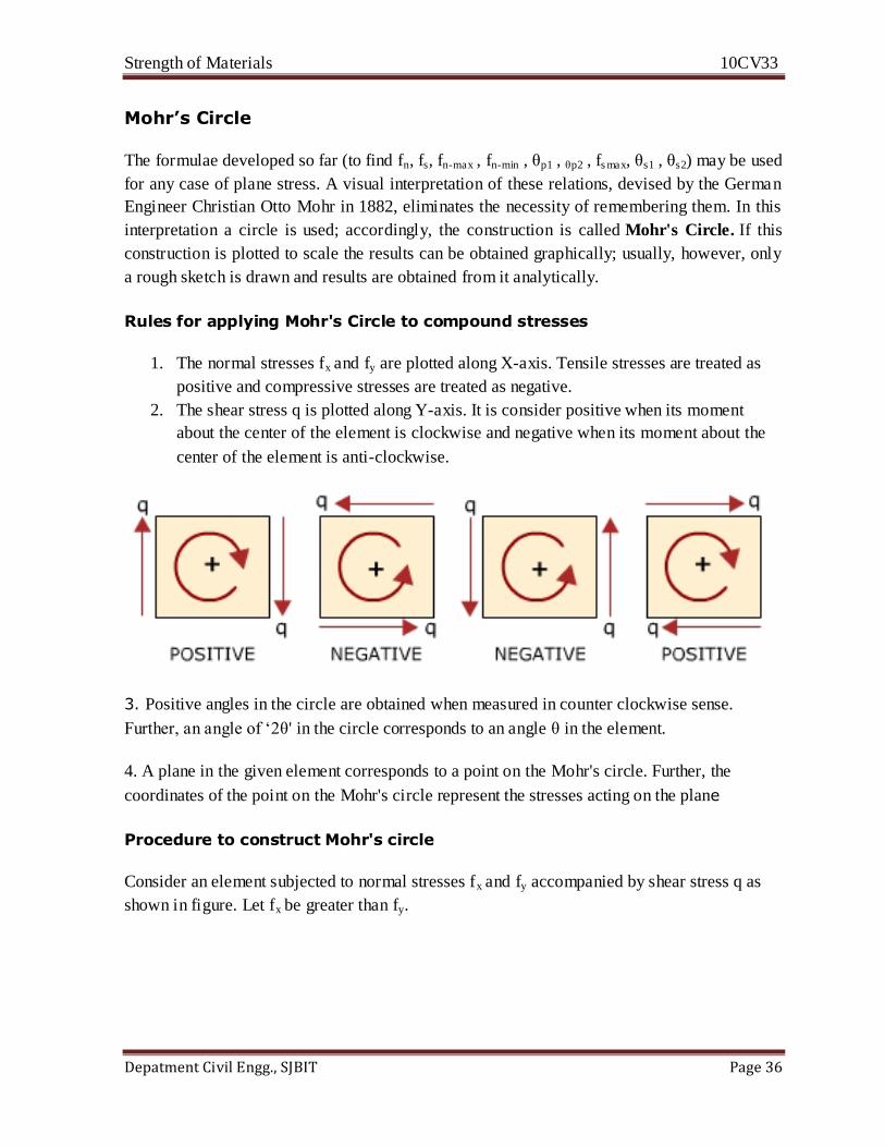
Rules for applying Mohr's Circle to compound stresses
1. The normal stresses fx and fy are plotted along X-axis. Tensile stresses are treated as
positive and compressive stresses are treated as negative.
2. The shear stress q is plotted along Y-axis. It is consider positive when its moment
about the center of the element is clockwise and negative when its moment about the
center of the element is anti-clockwise.
3. Positive angles in the circle are obtained when measured in counter clockwise sense.
Further, an angle of ‘2θ' in the circle corresponds to an angle θ in the element.
4. A plane in the given element corresponds to a point on the Mohr's circle. Further, the
coordinates of the point on the Mohr's circle represent the stresses acting on the plane
Procedure to construct Mohr's circle
Consider an element subjected to normal stresses fx and fy accompanied by shear stress q as
shown in figure. Let fx be greater than fy.
Strength of Materials 10CV33
Depatment Civil Engg., SJBIT Page 37
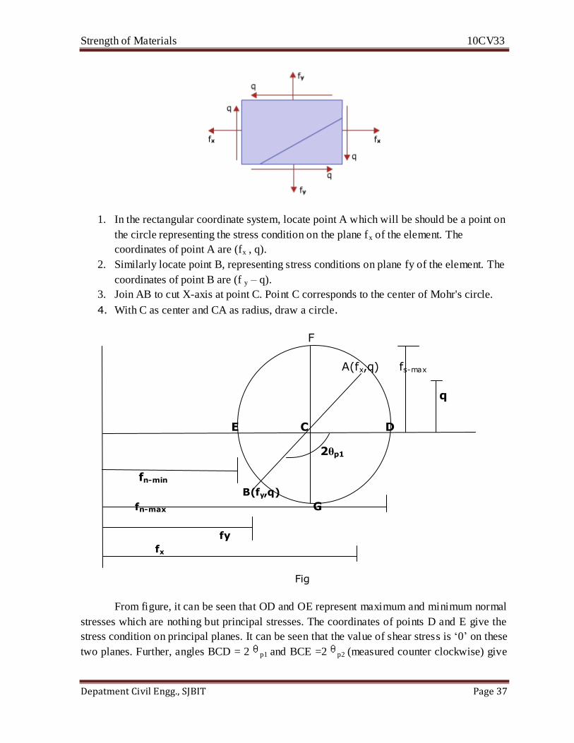
1. In the rectangular coordinate system, locate point A which will be should be a point on
the circle representing the stress condition on the plane fx of the element. The
coordinates of point A are (fx , q).
2. Similarly locate point B, representing stress conditions on plane fy of the element. The
coordinates of point B are (f y – q).
3. Join AB to cut X-axis at point C. Point C corresponds to the center of Mohr's circle.
4. With C as center and CA as radius, draw a circle.
F
A(fx,q) fs-max
q
E C D
2θp1
fn-min
B(fy,q)
fn-max G
fy
fx
Fig
From figure, it can be seen that OD and OE represent maximum and minimum normal
stresses which are nothing but principal stresses. The coordinates of points D and E give the
stress condition on principal planes. It can be seen that the value of shear stress is ‘0’ on these
two planes. Further, angles BCD = 2 p1 and BCE =2 p2 (measured counter clockwise) give
Strength of Materials 10CV33
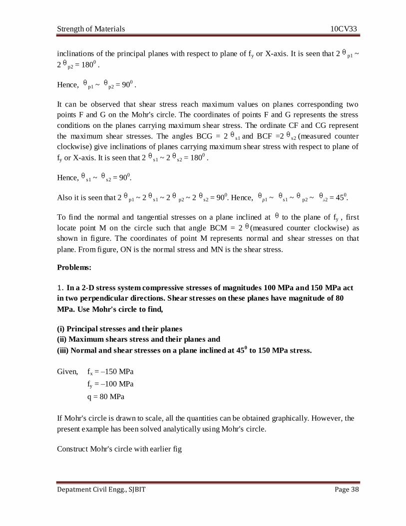
Depatment Civil Engg., SJBIT Page 38
inclinations of the principal planes with respect to plane of fy or X-axis. It is seen that 2 p1 ~
2 p2 = 1800 .
Hence, p1 ~ p2 = 900 .
It can be observed that shear stress reach maximum values on planes corresponding two
points F and G on the Mohr's circle. The coordinates of points F and G represents the stress
conditions on the planes carrying maximum shear stress. The ordinate CF and CG represent
the maximum shear stresses. The angles BCG = 2 s1 and BCF =2 s2 (measured counter
clockwise) give inclinations of planes carrying maximum shear stress with respect to plane of
fy or X-axis. It is seen that 2 s1 ~ 2 s2 = 1800 .
Hence, s1 ~ s2 = 900.
Also it is seen that 2 p1 ~ 2 s1 ~ 2 p2 ~ 2 s2 = 900. Hence, p1 ~ s1 ~ p2 ~ s2 = 450.
To find the normal and tangential stresses on a plane inclined at to the plane of fy , first
locate point M on the circle such that angle BCM = 2 (measured counter clockwise) as
shown in figure. The coordinates of point M represents normal and shear stresses on that
plane. From figure, ON is the normal stress and MN is the shear stress.
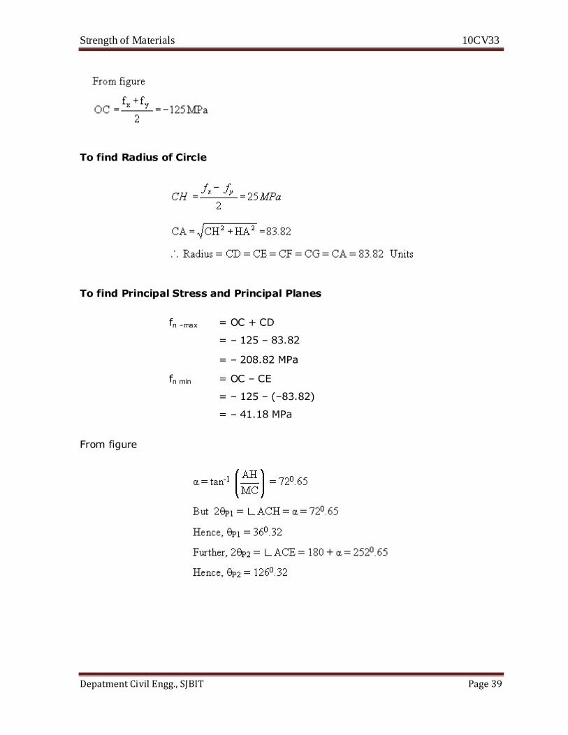
Problems:
1. In a 2-D stress system compressive stresses of magnitudes 100 MPa and 150 MPa act
in two perpendicular directions. Shear stresses on these planes have magnitude of 80
MPa. Use Mohr's circle to find,
(i) Principal stresses and their planes
(ii) Maximum shears stress and their planes and
(iii) Normal and shear stresses on a plane inclined at 450 to 150 MPa stress.
Given, fx = –150 MPa
fy = –100 MPa
q = 80 MPa
If Mohr's circle is drawn to scale, all the quantities can be obtained graphically. However, the
present example has been solved analytically using Mohr's circle.
Construct Mohr's circle with earlier fig
Strength of Materials 10CV33
Depatment Civil Engg., SJBIT Page 39
To find Radius of Circle
To find Principal Stress and Principal Planes
fn –max = OC + CD
= – 125 – 83.82
= – 208.82 MPa
fn min = OC – CE
= – 125 – (–83.82)
= – 41.18 MPa
From figure
Strength of Materials 10CV33
Depatment Civil Engg., SJBIT Page 40
Unit 4
Bending Moment and Shear Force
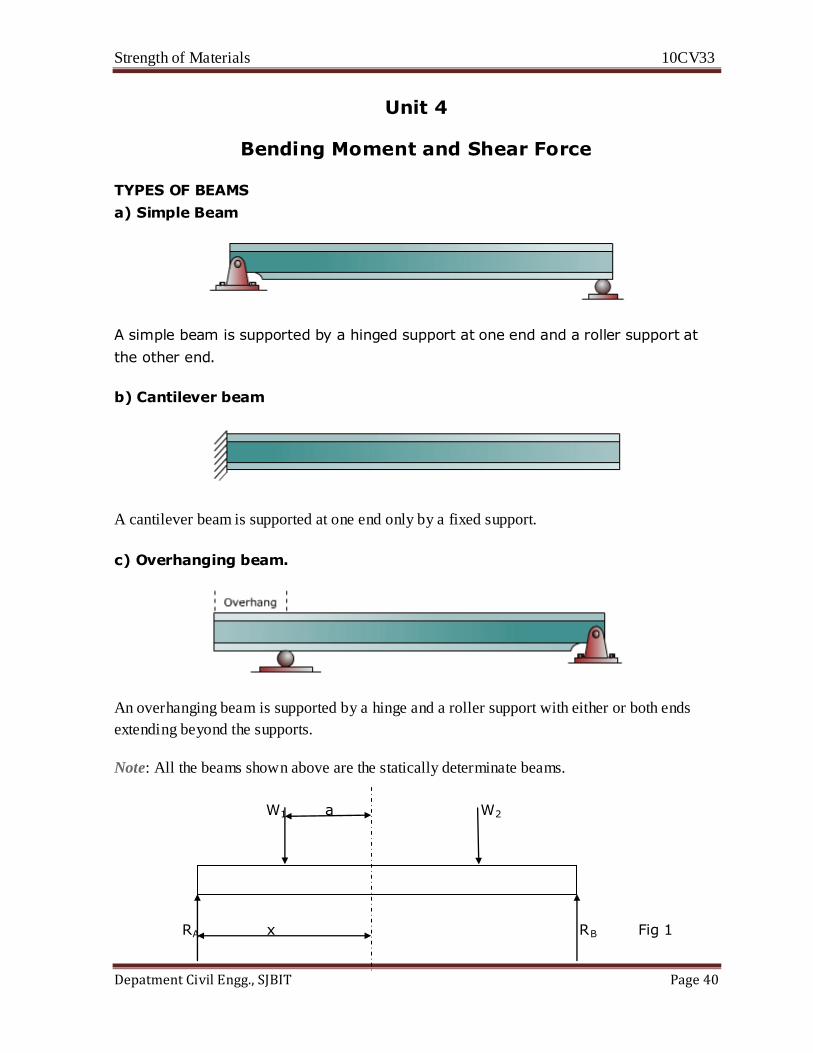
TYPES OF BEAMS
a) Simple Beam
A simple beam is supported by a hinged support at one end and a roller support at
the other end.
b) Cantilever beam
A cantilever beam is supported at one end only by a fixed support.
c) Overhanging beam.
An overhanging beam is supported by a hinge and a roller support with either or both ends
extending beyond the supports.
Note: All the beams shown above are the statically determinate beams.
W1 a W2
RA x RB Fig 1

Strength of Materials 10CV33
Depatment Civil Engg., SJBIT Page 41
W1
a
Rax-W1a
Ra
Fig 2 : Shear Force Fig 3 : Bending Moment
Consider a simply supported beam subjected to loads W1 and W2. Let RAand RB be the
reactions at supports. To determine the internal forces at C pass a section at C. The effects of
RA and W1 to the left of section are shown in Fig (b) and (c). In each case the effect of applied
load has been transferred to the section by adding a pair of equal and opposite forces at that
section. Thus at the section, moment M = (W1a-Rax) and shear force F = (RA-W1), exists. The
moment M which tend to bends the beam is called bending moment and F which tends to
shear the beam is called shear force.
Thus the resultant effect of the forces at one side of the section reduces to a single force and a
couple which are respectively the vertical shear and the bending moment at that section.
Similarly, if the equilibrium of the right hand side portion is considered, the loading is
reduced to a vertical force and a couple acting in the opposite direction. Applying these forces
to a free body diagram of a beam segment, the segments to the left and right of section are
held in equilibrium by the shear and moment at section.
Thus the shear force at any section can be obtained by considering the algebraic sum of all the
vertical forces acting on any one side of the section
Bending moment at any section can be obtained by considering the algebraic sum of all the
moments of vertical forces acting on any one side of the section.
Shear Force
It is a single vertical force developed internally at any point on the beam to balance the
external vertical forces and keep the point in equilibrium. It is therefore equal to algebraic sum
of all external forces acting to either left or right of the section.
Bending Moment
It is a moment developed internally at each point in a beam that balances the external
moments due to forces and keeps the point in equilibrium. It is the algebraic sum of moments
to section of all forces either on left or on right of the section.
Strength of Materials 10CV33
Depatment Civil Engg., SJBIT Page 42
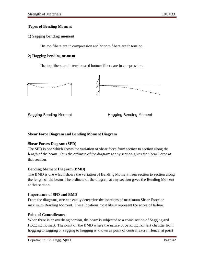
Types of Bending Moment
1) Sagging bending moment
The top fibers are in compression and bottom fibers are in tension.
2) Hogging bending moment
The top fibers are in tension and bottom fibers are in compression.
Sagging Bending Moment Hogging Bending Moment
Shear Force Diagram and Bending Moment Diagram
Shear Forces Diagram (SFD)
The SFD is one which shows the variation of shear force from section to section along the
length of the beam. Thus the ordinate of the diagram at any section gives the Shear Force at
that section.
Bending Moment Diagram (BMD)
The BMD is one which shows the variation of Bending Moment from section to section along
the length of the beam. The ordinate of the diagram at any section gives the Bending Moment
at that section.
Importance of SFD and BMD
From the diagrams, one can easily determine the locations of maximum Shear Force or
maximum Bending Moment. These locations most likely represent the zones of failure.
Point of Contraflexure
When there is an overhang portion, the beam is subjected to a combination of Sagging and
Hogging moment. The point on the BMD where the nature of bending moment changes from
hogging to sagging or sagging to hogging is known as point of contraflexure. Hence, at point
Strength of Materials 10CV33
Depatment Civil Engg., SJBIT Page 43
of contraflexure BM is zero. The point corresponding to point of contraflexure on the beam is
called as point of inflection.
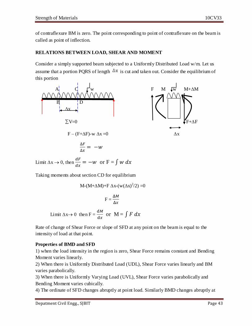
RELATIONS BETWEEN LOAD, SHEAR AND MOMENT
Consider a simply supported beam subjected to a Uniformly Distributed Load w/m. Let us
assume that a portion PQRS of length is cut and taken out. Consider the equilibrium of
this portion
A C w F M w M+M
B D
x
∑V=0 F+F
F – (F+F)-w x =0 x
Limit x 0, then
or F =
Taking moments about section CD for equilibrium
M-(M+M)+F x-(w(x)2/2) =0
F =
Limit x 0 then F =
or M =
Rate of change of Shear Force or slope of SFD at any point on the beam is equal to the
intensity of load at that point.
Properties of BMD and SFD
1) when the load intensity in the region is zero, Shear Force remains constant and Bending
Moment varies linearly.
2) When there is Uniformly Distributed Load (UDL), Shear Force varies linearly and BM
varies parabolically.
3) When there is Uniformly Varying Load (UVL), Shear Force varies parabolically and
Bending Moment varies cubically.
4) The ordinate of SFD changes abruptly at point load. Similarly BMD changes abruptly at
Strength of Materials 10CV33
Depatment Civil Engg., SJBIT Page 44
points where couple is acting.
5) The maximum or minimum Bending Moment occurs at a point where shear force is zero.
Problems:
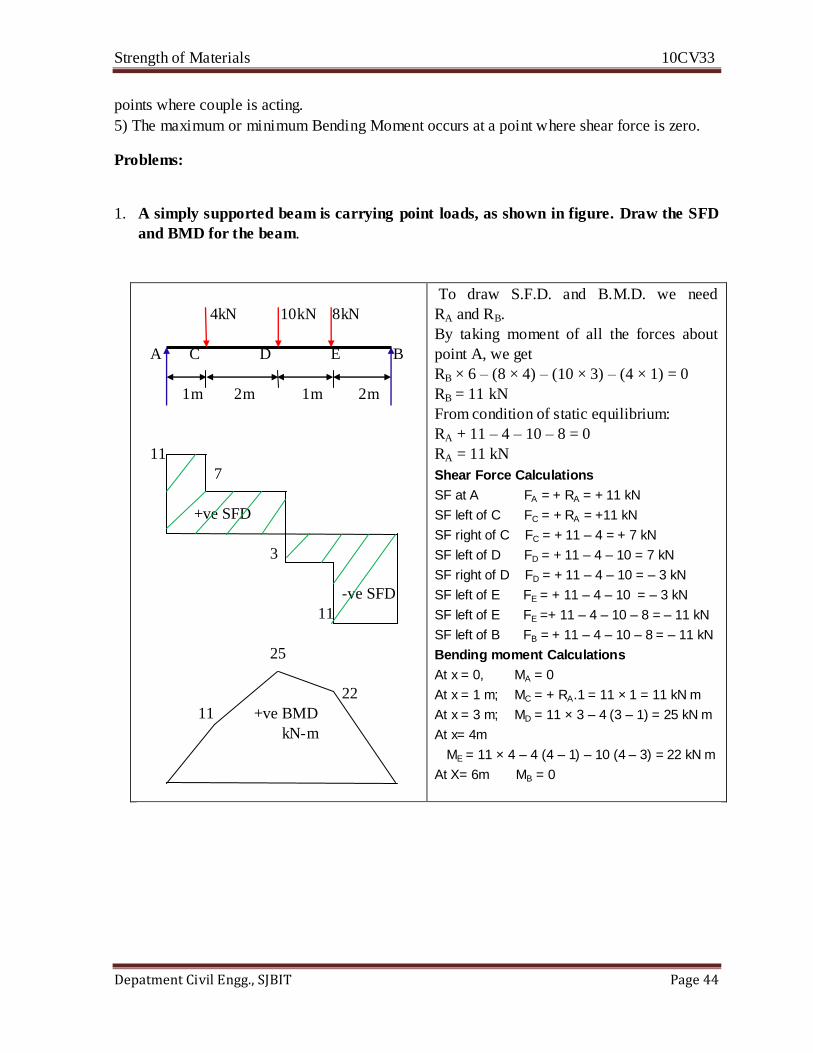
1. A simply supported beam is carrying point loads, as shown in figure. Draw the SFD
and BMD for the beam.
4kN 10kN 8kN
A C D E B
1m 2m 1m 2m
11
7
+ve SFD
3
-ve SFD
11
25
22
11 +ve BMD
kN-m
To draw S.F.D. and B.M.D. we need
RA and RB.
By taking moment of all the forces about
point A, we get
RB × 6 – (8 × 4) – (10 × 3) – (4 × 1) = 0
RB = 11 kN
From condition of static equilibrium:
RA + 11 – 4 – 10 – 8 = 0
RA = 11 kN
Shear Force Calculations
SF at A FA = + RA = + 11 kN
SF left of C FC = + RA = +11 kN
SF right of C FC = + 11 – 4 = + 7 kN
SF left of D FD = + 11 – 4 – 10 = 7 kN
SF right of D FD = + 11 – 4 – 10 = – 3 kN
SF left of E FE = + 11 – 4 – 10 = – 3 kN
SF left of E FE =+ 11 – 4 – 10 – 8 = – 11 kN
SF left of B FB = + 11 – 4 – 10 – 8 = – 11 kN
Bending moment Calculations
At x = 0, MA = 0
At x = 1 m; MC = + RA.1 = 11 × 1 = 11 kN m
At x = 3 m; MD = 11 × 3 – 4 (3 – 1) = 25 kN m
At x= 4m
ME = 11 × 4 – 4 (4 – 1) – 10 (4 – 3) = 22 kN m
At X= 6m MB = 0
Strength of Materials 10CV33
Depatment Civil Engg., SJBIT Page 45
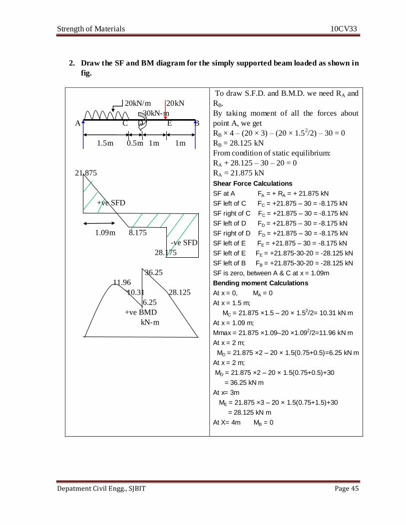
2. Draw the SF and BM diagram for the simply supported beam loaded as shown in
fig.
20kN/m 20kN
30kN-m
A C D E B
1.5m 0.5m 1m 1m
21.875
+ve SFD
1.09m 8.175
-ve SFD
28.175
36.25
11.96
10.31 28.125
6.25
+ve BMD
kN-m
To draw S.F.D. and B.M.D. we need RA and
RB.
By taking moment of all the forces about
point A, we get
RB × 4 – (20 × 3) – (20 × 1.52/2) – 30 = 0
RB = 28.125 kN
From condition of static equilibrium:
RA + 28.125 – 30 – 20 = 0
RA = 21.875 kN
Shear Force Calculations
SF at A FA = + RA = + 21.875 kN
SF left of C FC = +21.875 – 30 = -8.175 kN
SF right of C FC = +21.875 – 30 = -8.175 kN
SF left of D FD = +21.875 – 30 = -8.175 kN
SF right of D FD = +21.875 – 30 = -8.175 kN
SF left of E FE = +21.875 – 30 = -8.175 kN
SF left of E FE = +21.875-30-20 = -28.125 kN
SF left of B FB = +21.875-30-20 = -28.125 kN
SF is zero, between A & C at x = 1.09m
Bending moment Calculations
At x = 0, MA = 0
At x = 1.5 m;
MC = 21.875 ×1.5 – 20 × 1.52/2= 10.31 kN m
At x = 1.09 m;
Mmax = 21.875 ×1.09–20 ×1.092/2=11.96 kN m
At x = 2 m;
MD = 21.875 ×2 – 20 × 1.5(0.75+0.5)=6.25 kN m
At x = 2 m;
MD = 21.875 ×2 – 20 × 1.5(0.75+0.5)+30
= 36.25 kN m
At x= 3m
ME = 21.875 ×3 – 20 × 1.5(0.75+1.5)+30
= 28.125 kN m
At X= 4m MB = 0
Strength of Materials 10CV33
Depatment Civil Engg., SJBIT Page 46
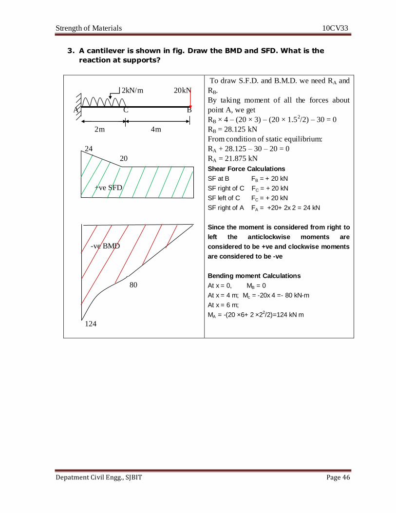
3. A cantilever is shown in fig. Draw the BMD and SFD. What is the
reaction at supports?
2kN/m 20kN
A C B
2m 4m
24
20
+ve SFD
-ve BMD
80
124
To draw S.F.D. and B.M.D. we need RA and
RB.
By taking moment of all the forces about
point A, we get
RB × 4 – (20 × 3) – (20 × 1.52/2) – 30 = 0
RB = 28.125 kN
From condition of static equilibrium:
RA + 28.125 – 30 – 20 = 0
RA = 21.875 kN
Shear Force Calculations
SF at B FB = + 20 kN
SF right of C FC = + 20 kN
SF left of C FC = + 20 kN
SF right of A FA = +20+ 2x 2 = 24 kN
Since the moment is considered from right to
left the anticlockwise moments are
considered to be +ve and clockwise moments
are considered to be -ve
Bending moment Calculations
At x = 0, MB = 0
At x = 4 m; Mc = -20x 4 =- 80 kN-m
At x = 6 m;
MA = -(20 ×6+ 2 ×22/2)=124 kN m
Strength of Materials 10CV33
Depatment Civil Engg., SJBIT Page 47
Unit 5
Stresses in Beams
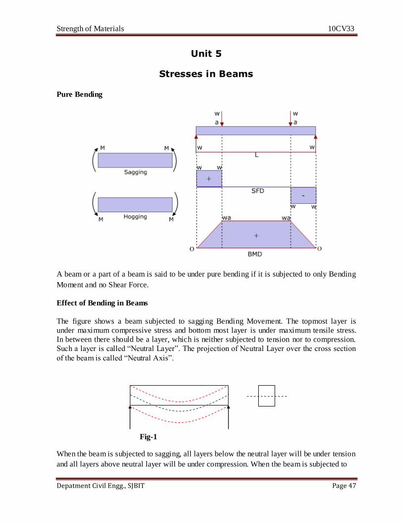
Pure Bending
A beam or a part of a beam is said to be under pure bending if it is subjected to only Bending
Moment and no Shear Force.
Effect of Bending in Beams
The figure shows a beam subjected to sagging Bending Movement. The topmost layer is
under maximum compressive stress and bottom most layer is under maximum tensile stress.
In between there should be a layer, which is neither subjected to tension nor to compression.
Such a layer is called “Neutral Layer”. The projection of Neutral Layer over the cross section
of the beam is called “Neutral Axis”.
Fig-1
When the beam is subjected to sagging, all layers below the neutral layer will be under tension
and all layers above neutral layer will be under compression. When the beam is subjected to
Strength of Materials 10CV33
Depatment Civil Engg., SJBIT Page 48
hogging, all layers above the neutral layer will be under tension and all the layers below
neutral layer will be under compression and vice versa if it is hogging bending moment
Assumptions made in simple bending theory
The material is isotropic and homogenous.
The material is perfectly elastic and obeys Hooke's Law i.e., the stresses are within the
limit of proportionality.
Initially the beam is straight and stress free.
Beam is made up of number of layers and they undergo bending independently.
Bending takes place over an arc of a circle and the radius of curvature is very large
when compared to the dimensions of the beam.
Normal plane sections before bending remain normal and plane even after bending.
Young's Modulus of Elasticity is same under tension and compression.
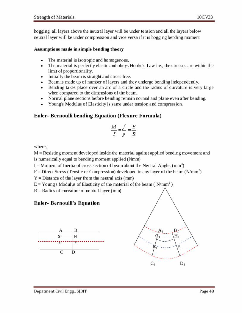
Euler- Bernoulli bending Equation (Flexure Formula)
where,
M = Resisting moment developed inside the material against applied bending movement and
is numerically equal to bending moment applied (Nmm)
I = Moment of Inertia of cross section of beam about the Neutral Angle. (mm4)
F = Direct Stress (Tensile or Compression) developed in any layer of the beam (N/mm2)
Y = Distance of the layer from the neutral axis (mm)
E = Young's Modulus of Elasticity of the material of the beam ( N/mm2 )
R = Radius of curvature of neutral layer (mm)
Euler- Bernoulli’s Equation
A B A1 B1
G1 H1
C D
E1 F1
C D
C1 D1
G H
E F
Strength of Materials 10CV33
Depatment Civil Engg., SJBIT Page 49
Consider two section very close together (AB and CD). After bending the sections will be at
A1 B1 and C1 D1 and are no longer parallel. AC will have extended to A1 C1 and B1 D1 will
have compressed to B1D1. The line EF will be located such that it will not change in length.
This surface is called neutral surface and its intersection with Z-Z is called the neutral axis.
The development lines of A'B' and C'D' intersect at a point 0 at an angle of θ radians and the
radius of E1F1 = R.
Let y be the distance(E'G') of any layer H1G1 originally parallel to EF.
Then H1G1/ E1F1 =(R+y)θ /R θ = (R+y)/R
and the strain at layer H1G1= = (H1G1'- HG) / HG = (H1G1- HG) / EF
= [(R+y)θ - R θ] /R θ
= y /R.
The relation between stress and strain is σ= E. Therefore
σ = E. = E. y /R
σ / E = y / R
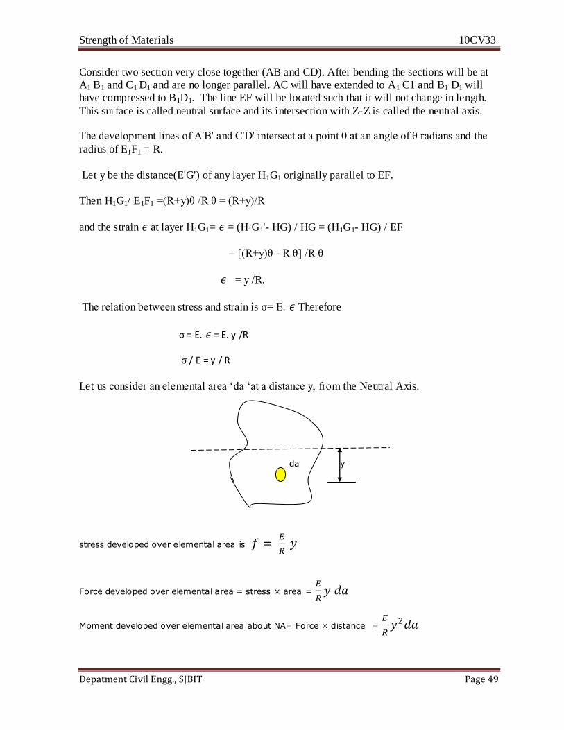
Let us consider an elemental area ‘da ‘at a distance y, from the Neutral Axis.
da y
stress developed over elemental area is
Force developed over elemental area = stress × area =
Moment developed over elemental area about NA= Force × distance =
Strength of Materials 10CV33
Depatment Civil Engg., SJBIT Page 50
Total Moment developed from all the elements about the NA =
M=
=
…………..(2)
From Eqn (1) and (2), we get
…………..(A)
Section Modulus(Z)
Section modulus of a beam is the ratio of moment of inertia of the cross section of the beam
about the neutral axis to the distance of the farthest fiber from neutral axis.
More the section modulus more will be the moment of resistive (or) moment carrying capacity
of the beam. For the strongest beam, the section modulus must be maximum.
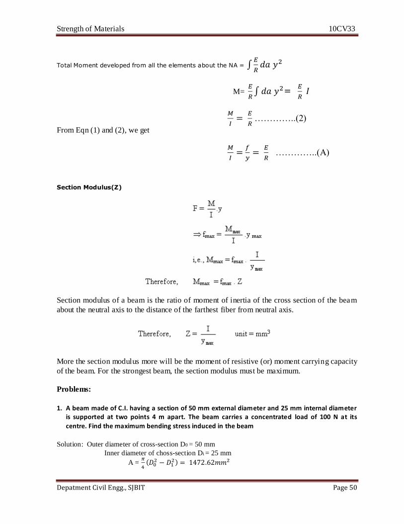
Problems:
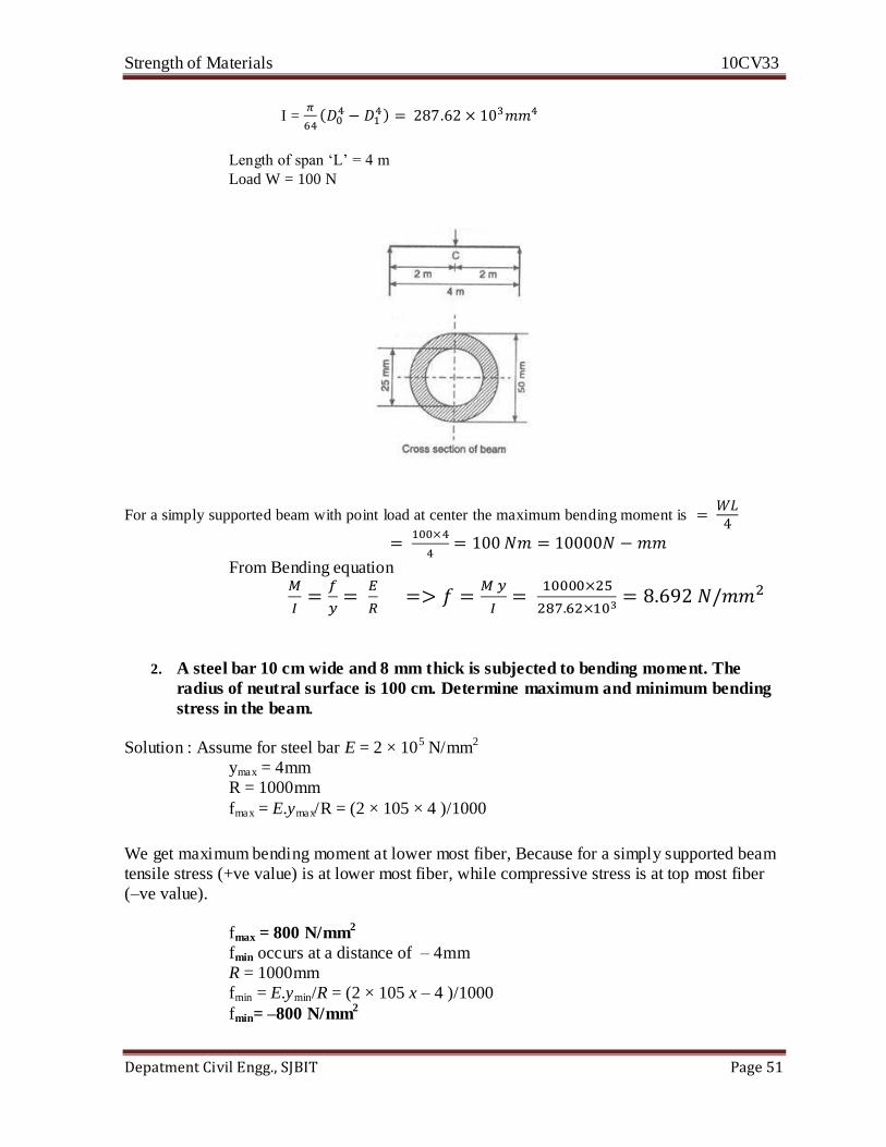
1. A beam made of C.I. having a section of 50 mm external diameter and 25 mm internal diameter
is supported at two points 4 m apart. The beam carries a concentrated load of 100 N at its
centre. Find the maximum bending stress induced in the beam
Solution: Outer diameter of cross-section D0 = 50 mm
Inner diameter of choss-section Di = 25 mm
A =
Strength of Materials 10CV33
Depatment Civil Engg., SJBIT Page 51
I =
Length of span ‘L’ = 4 m
Load W = 100 N
For a simply supported beam with point load at center the maximum bending moment is
From Bending equation
2. A steel bar 10 cm wide and 8 mm thick is subjected to bending moment. The
radius of neutral surface is 100 cm. Determine maximum and minimum bending
stress in the beam.
Solution : Assume for steel bar E = 2 × 10⁵ N/mm2
ymax = 4mm
R = 1000mm
fmax = E.ymax/R = (2 × 105 × 4 )/1000
We get maximum bending moment at lower most fiber, Because for a simply supported beam
tensile stress (+ve value) is at lower most fiber, while compressive stress is at top most fiber
(–ve value).
fmax = 800 N/mm2
fmin occurs at a distance of – 4mm
R = 1000mm
fmin = E.ymin/R = (2 × 10⁵ x – 4 )/1000
fmin= –800 N/mm2
Strength of Materials 10CV33
Depatment Civil Engg., SJBIT Page 52
3. A simply supported rectangular beam with symmetrical section 200mm in depth
has moment of inertia of 2.26 x 10⁻⁵
m4
about its neutral axis. Determine the
longest span over which the beam would carry a uniformly distributed load of
4kN/m run such that the stress due to bending does not exceed 125 MN/m2.
Solution: Given data:
Depth d = 200mm = 0.2m
I = Moment of inertia = 2.26 × 10⁻⁵ m4
UDL = 4kN/m
Bending stress s = 125 MN/m2 = 125 × 106 N/m2
Span = ?
Since we know that Maximum bending moment for a simply supported beam with UDL on its
entire span is given by = WL2/8
i.e; M = WL2/8 -------------(A)
From bending equation M/I = f/ymax
ymax = d/2 = 0.2/2 = 0.1m
M = f.I/ymax = [(125 × 106) × (2.26 × 10-5)]/ 0.1 = 28250 Nm
Substituting this value in equation (A); we get
28250 = (4 × 10³)L2/8
L = 7.52m
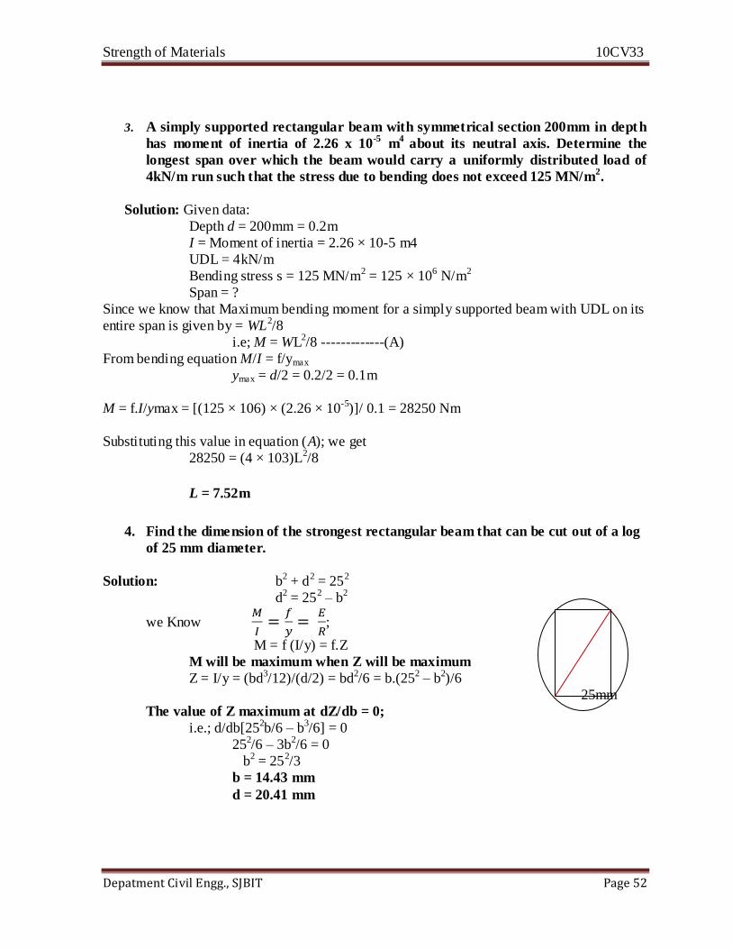
4. Find the dimension of the strongest rectangular beam that can be cut out of a log
of 25 mm diameter.
Solution: b2 + d2 = 252
d2 = 252 – b2
we Know
;
M = f (I/y) = f.Z
M will be maximum when Z will be maximum
Z = I/y = (bd3/12)/(d/2) = bd2/6 = b.(252 – b2)/6
25mm
The value of Z maximum at dZ/db = 0;
i.e.; d/db[252b/6 – b3/6] = 0
252/6 – 3b2/6 = 0
b2 = 252/3
b = 14.43 mm
d = 20.41 mm

Strength of Materials 10CV33
Depatment Civil Engg., SJBIT Page 53
Unit 6
Deflection of Beams
INTRODUCTION
Under the action of external loads, the beam is subjected to stresses and deformation at
various points along the length. The deformation is caused due to bending moment and shear
force. Since the deformation caused due to shear force in shallow beams is very small, it is
generally neglected.
Elastic Line:
It is a line which represents the deformed shape of the beam. Hence, it is the line along which
the longitudinal axis of the beam bends.
Deflection:
Vertical displacement measured from original neutral surface (refer to earlier chapter) to the
neutral surface of the deformed beam.
Slope:
Angle made by the tangent to the elastic curve with respect to horizontal
The designers have to decide the dimensions of beam not only based on strength requirement
but also based on considering deflection. In mechanical components excessive deflection
causes mis-alignment and non performance of machine. In building it give rise to
psychological unrest and sometimes cracks in roofing materials. Deflection calculations are
required to impose consistency conditions in the analysis of indeterminate structures.
W
θA θB
y
Strength:
It is a measure of the resistance offered by the beam to load
Strength of Materials 10CV33
Depatment Civil Engg., SJBIT Page 54
Stiffness:
It is a measure at the resistance offered by the beam to deformation. Usually span / deflection
is used to denote the stiffness. Greater the stiffness, smaller will be the deflection. The term
(EI) called “flexural rigidity” and is used to denote the stiffness.
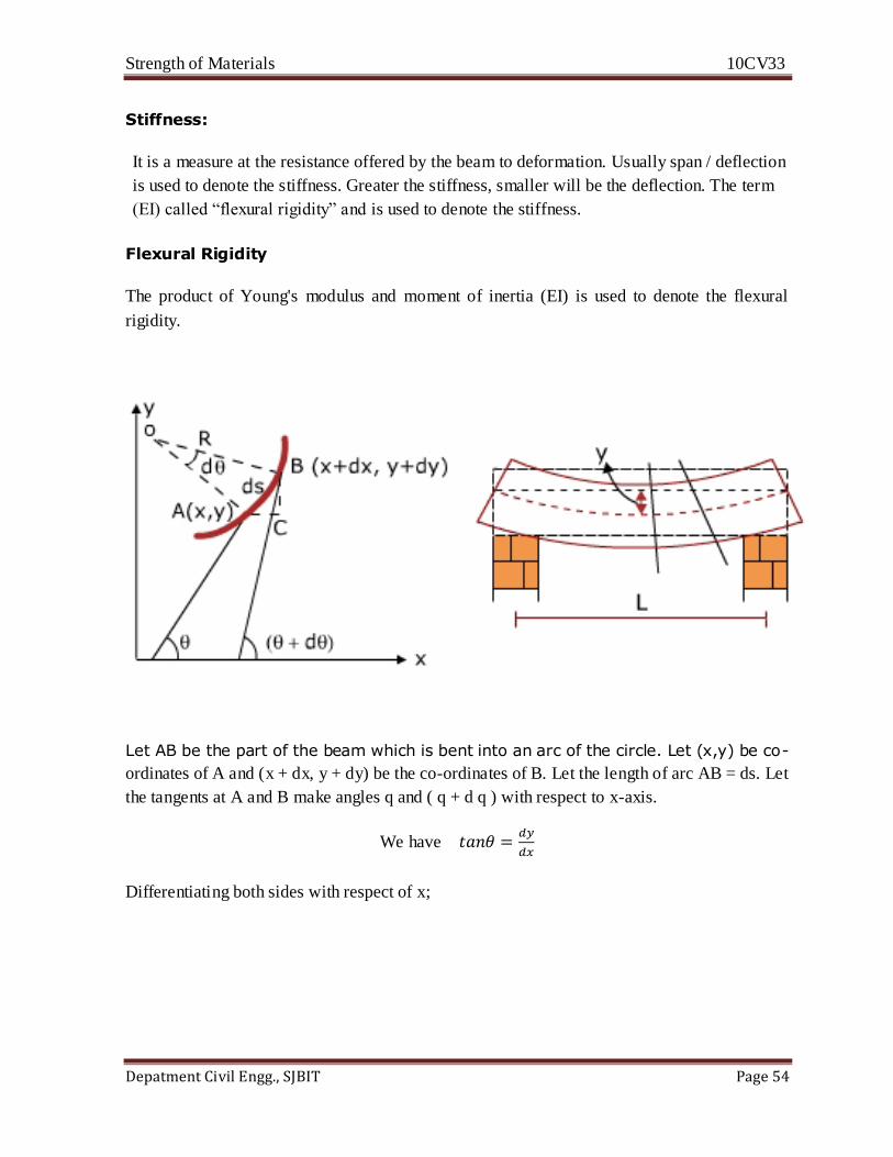
Flexural Rigidity
The product of Young's modulus and moment of inertia (EI) is used to denote the flexural
rigidity.
Let AB be the part of the beam which is bent into an arc of the circle. Let (x,y) be co-
ordinates of A and (x + dx, y + dy) be the co-ordinates of B. Let the length of arc AB = ds. Let
the tangents at A and B make angles q and ( q + d q ) with respect to x-axis.
We have
Differentiating both sides with respect of x;

Strength of Materials 10CV33
Depatment Civil Engg., SJBIT Page 55
Since dy/dx is small, its square is still small, neglecting (dy/dx)2 ; we have
This is also known as Euler - Bernoulli's equation.

Strength of Materials 10CV33
Depatment Civil Engg., SJBIT Page 56
NOTE:
While deriving Y-axis is taken upwards
Curvature is concave towards the positive y axis.
This occurs for sagging BM, which is positive.
Sign Convention
Bending moment Sagging + vc
If Y is +ve - Deflection is upwards
Y is –ve - Deflection is downwards
If is +ve – Slope is Anticlockwise
is - ve – Slope is clockwise
Methods of Calculating Deflection and Slope
Double Integration method
Macaulay's method
Strain energy method
Moment area method
Conjugate Beam method
Each method has certain advantages and disadvantages.
Relationship between Loading, S.F, BM, Slope and Deflection

Strength of Materials 10CV33
Depatment Civil Engg., SJBIT Page 57
Macaulay's Method
1. Take the origin on the extreme left.
2. Take a section in the last segment of the beam and calculate BM by considering left
portion.
3. Integrate (x-a) using the formula
4. If the expression (x-a)n becomes negative on substituting the value of x, neglect the terms
containing the factor (x-a)n
5. If the beam carries UDL and if the section doesn't cuts the UDL, extend the UDL upto the
section and impose a UDL in the opposite direction to counteract it.
6. If a couple is acting, the BM equation is modified as; M = R A x + M (x-a)0.
7. The constant C1 and C2 all determined using boundary conditions.
a) S.S. Beam – Deflection is zero at supports
b) Cantilever – Deflection and slope are zero at support.
Problems:
1. Determine the maximum deflection in a simply supported beam of length L carrying a
concentrated load P at its midspan.
P
A B
L/2
L

Strength of Materials 10CV33
Depatment Civil Engg., SJBIT Page 58
…………………(1)
…………………(2)
At x =0; y =0 C2 =0
At x = L y =0
Maximum deflection occurs at x = L/2
Substituting the values of x and C1 in equation…. (2)
The negative sign indicates that the deflection is below the undeformed neural axis
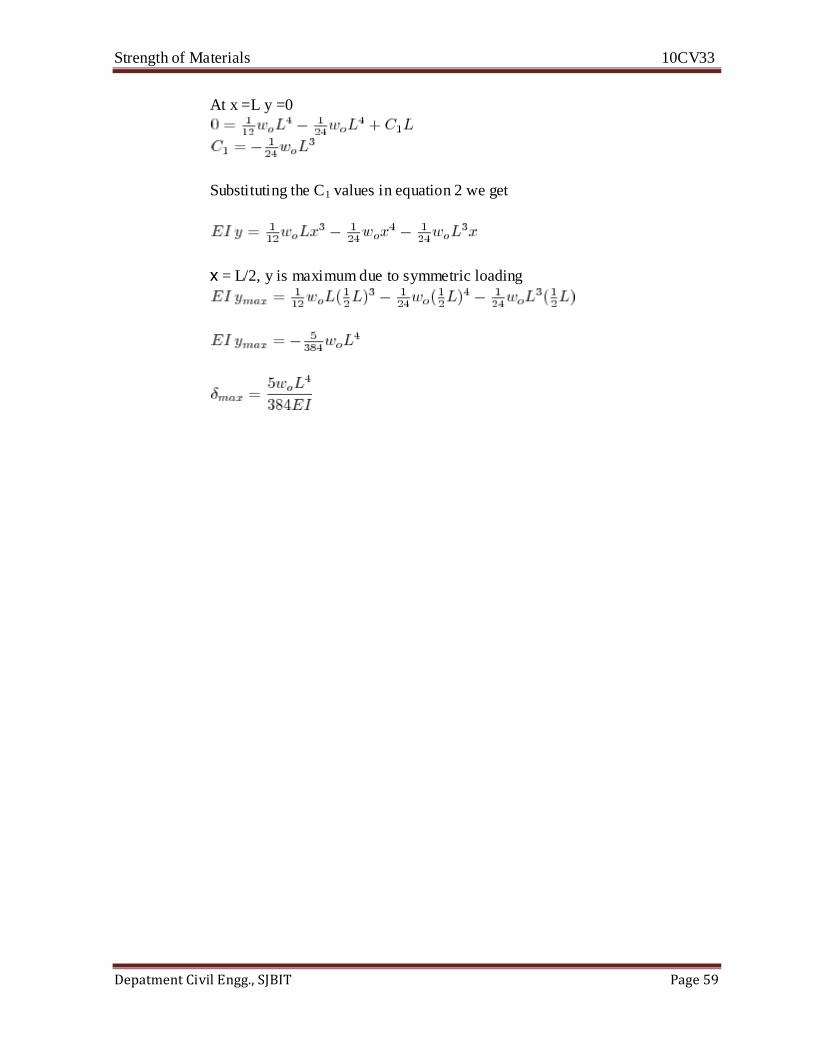
3. Determine the maximum deflection in a simply supported beam of length L
carrying a uniformly distributed load ‘w’ for the entire length of the beam.
Solution : From the following fig
w
L
………………..(1)
…………(2)
At x =0 y=0 and C2 =0
Strength of Materials 10CV33
Depatment Civil Engg., SJBIT Page 59
At x =L y =0
Substituting the C1 values in equation 2 we get
x = L/2, y is maximum due to symmetric loading
Strength of Materials 10CV33
Depatment Civil Engg., SJBIT Page 60
UNIT 7
TORSION OF SHAFTS
Bending Moment
The moment applied in a vertical plane containing the longitudinal axis is resisted by
longitudinal tensile and compressive stresses of varying intensities across the depth of beam
and are called as bending stresses. The moment applied is called Bending Moment.
Torsional Moment
The moment applied in a vertical plane perpendicular to the longitudinal axis i.e., in the plane
of the cross section of the member, it causes twisting of layers which will be resisted by the
shear stresses. The moment applied is called Torsion Moment or Torsional Moment. Torsion
is useful form of transmitting power and its application is seen in screws and shafts.
PURE TORSION
A circular member is said to be in a state of pure torsion when it is subjected to a twisting
moment which coincides with the axis of the shaft and not accompanied by bending and axial
force.
ASSUMPTIONS IN TORSION THEORY
1. Material is homogenous and isotropic
2. Plane section remain plane before and after twisting i.e., no warpage of planes.
3. Twist along the shaft is uniform.
4. Radii which are straight before twisting remain straight after twisting.
5. Stresses are within the proportional limit.
DERIVATION OF TORSIONAL EQUATION:
Torsional Rigidity
As product (CIP ) is increased deformation q reduces. This product gives the strength of the
section to resist torque and is called Torsional rigidity.
Strength of Materials 10CV33
Depatment Civil Engg., SJBIT Page 61
Polar Modulus : (ZP)
POWER TRANSMITTED BY SHAFT
Power transmitted = Torsional moment x Angle through which the torsional moment rotates /
unit tank
If the shaft rotates with ‘N' rpm
Note:
N is in rpm and T is in N-m
Problems:
1. Find the maximum shear stress induced in a solid circular shaft of diameter 200
mm when the shaft transmits 190 kW power at 200 rpm
Given data: Power transmitted, P = 190 kW, Ip =
1.57 X 108 mm4
speed N = 200 rpm and diameter of shaft = 200 mm.
Strength of Materials 10CV33
Depatment Civil Engg., SJBIT Page 62
T
N-mm
From the formulae
Substituting all the values fs = 5.78N/mm2.
2. A solid shaft of mild steel 200 mm in diameter is to be replaced by hollow shaft of
allowable shear stress is 22% greater. If the power to be transmitted is to be
increased by 20% and the speed of rotation increased by 6%, determine the
maximum internal diameter of the hollow shaft. The external diameter of the hollow
shaft is to be 200 mm.
Solution: Given that:
Diameter of solid shaft d = 200 mm
For hollow shaft diameter, d0 = 200 mm
Shear stress; tH = 1.22 ts
Power transmitted; PH = 1.20 Ps
Speed NH = 1.06 Ns
As the power transmitted by hollow shaft
PH = 1.20 Ps
(2π.NH.TH)/60 = (2π.Ns.Ts)/60 × 1.20
NH.TH = 1.20 Ns.Ts
1.06 Ns.TH = 1.20 NsTs
1.06/1.20 TH = Ts
1.06/1.20 × π/16 tH [(d0)4 – (di)
4/d0] = π/16 ts.[d]3
1.06/1.20 × 1.22 ts [(200)4 – (di)4/200] = ts × [200]3
di = 104 mm
3. A solid shaft is subjected to a maximum torque of 1.5 MN.cm Estimate the diameter
for the shaft, if the allowable shearing stress and the twist are limited to 1 kN/cm2 and
1o respectively for 200 cm length of shaft. Take G = 80 × 105 N/cm
2
Solution: Since we have
T/Ip = fs/r = C.θ/L
fs = T.Ip r = 1.5 × 10⁶ / θ/32.d4 . d/2
1 × 103 * 2π /1.5 × 106 * 32 = 1/d3
d = 19.69 cm
θ = T.L / C.Ip
1.5 × 106 * 2π / 1.5 × 106 * 32 = 1 / d3
d = 19.69 cm
θ = T.L / C.Ip
1.5 × 106 * 200 d/80 * 105 * π/32 d4 = π/180
Strength of Materials 10CV33
Depatment Civil Engg., SJBIT Page 63
d3 = 1.5 × 106 * 180 * 200 * 32 / (80 * 105 * π * π)
d = 27.97 cm
4. A hollow circular shaft of 20 mm thickness transmits 300 kW power at 200 r.p.m.
Determine the external diameter of the shaft if the shear strain due to torsion is
not to exceed 0.00086. Take modulus of rigidity = 0.8 × 10⁵ N/mm
2.
Solution: Let di = inner diameter of circular shaft
d0 = outer diameter of circular shaft
Then d0 = di + 2t where t = thickness
d0 = di + 2 * 20
d0 = di + 40
di = d0 – 40
Since we have
Power transmitted = 2π NT/60
300,000 = 2π * 200 * T / 60
→ T = 14323900 N mm
Also, we have C = fs/y
→ 0.8 * 105 = fs /0.00086
→ fs = 68.8 N/mm2
Now T = π/16. fs.(d04 – di
4 / d0)
14323900 = fs /16 * 68.8 (d04 – (d0 – 40)4 / d0)
1060334.6 d0 = d04 – (d0 – 40)4
= (d02 – d0
2 + 80d0 – 1600)*(d02 + d0
2 – 80d0 + 1600)
= (80d0 – 1600) (2d02 – 80d0 + 1600)
= 80 (d0 – 20) * 2 * (d02 – 40 d0 + 800)
= 160 (d03 – 40d0
2 + 800 d0 – 20 d02 + 800 d0 – 16000)
→ 1060334.6 d0 / 160 = d03 – 60d0
2 + 1600d0 – 16000
→ 6627 d0 = d03 – 60d0
2 + 1600 d0 – 1600
→ d03 – 60d0
2 + 1600d0 – 6627 d0 – 16000 = 0
→ d03 – 60d0
2 – 5027 d0 – 16000 = 0
Using trial and error method to solve the above equation for d0, we get d0 = 107.5 mm.
Strength of Materials 10CV33
Depatment Civil Engg., SJBIT Page 64
Unit 8
Elastic Stability of Columns
Columns and Struts:
Columns and struts are structural members subjected to compressive forces. Theses members
are often subjected to axial forces, although they may be loaded eccentrically. The lengths of
these members are large compared to their lateral dimensions. In general vertical compressive
members called columns and inclined compressive members are called struts.
CLASSIFICATION OF COLUMNS:
Columns are generally classified in to three general types. The distinction between types of
columns is not well, but a generally accepted measure is based on the slenderness ratio
(le/r min).
Short Column :
A short column essentially fails by crushing and not by buckling. A column is said to be short,
if le /b 15 or le /rmin 50, where le = effective length, b = least lateral dimension and r min=
minimum radius of gyration.
Long Column :
A long column essentially fails by buckling and not by crushing. In long columns, the stress at
failure is less than the yield stress. A column is said to be long le/b > 15 or le /rmin> 50.
Intermediate Column :
An intermediate column is one which fails by a combination of crushing and buckling.
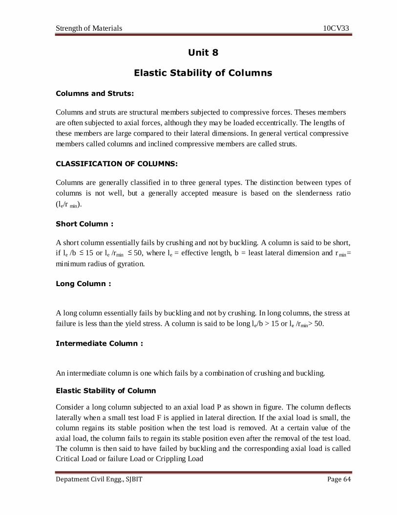
Elastic Stability of Column
Consider a long column subjected to an axial load P as shown in figure. The column deflects
laterally when a small test load F is applied in lateral direction. If the axial load is small, the
column regains its stable position when the test load is removed. At a certain value of the
axial load, the column fails to regain its stable position even after the removal of the test load.
The column is then said to have failed by buckling and the corresponding axial load is called
Critical Load or failure Load or Crippling Load
Strength of Materials 10CV33
Depatment Civil Engg., SJBIT Page 65
P P
F
P
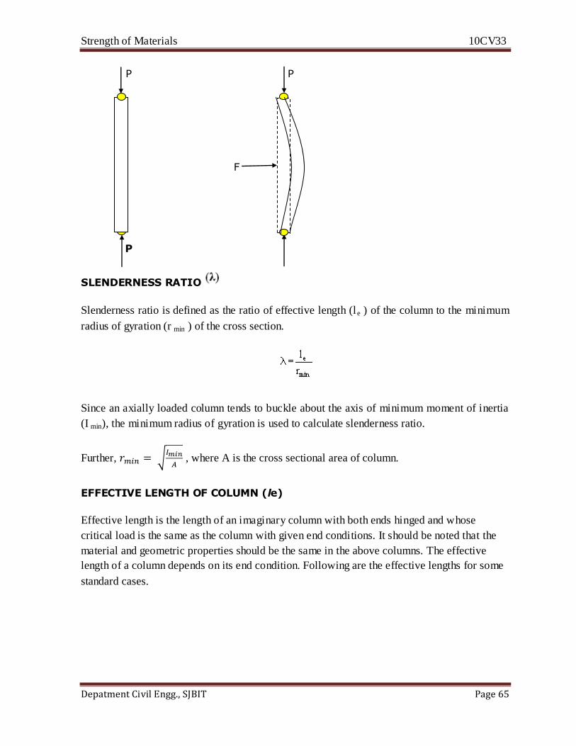
SLENDERNESS RATIO
Slenderness ratio is defined as the ratio of effective length (le ) of the column to the minimum
radius of gyration (r min ) of the cross section.
Since an axially loaded column tends to buckle about the axis of minimum moment of inertia
(I min), the minimum radius of gyration is used to calculate slenderness ratio.
Further,
, where A is the cross sectional area of column.
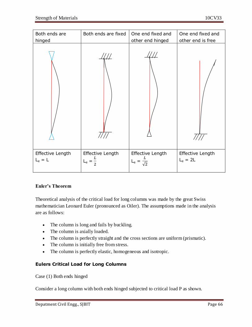
EFFECTIVE LENGTH OF COLUMN (le)
Effective length is the length of an imaginary column with both ends hinged and whose
critical load is the same as the column with given end conditions. It should be noted that the
material and geometric properties should be the same in the above columns. The effective
length of a column depends on its end condition. Following are the effective lengths for some
standard cases.
Strength of Materials 10CV33
Depatment Civil Engg., SJBIT Page 66
Both ends are
hinged
Both ends are fixed One end fixed and
other end hinged
One end fixed and
other end is free
Effective Length
Le = L
Effective Length
Le =
Effective Length
Le =
Effective Length
Le = 2L
Euler’s Theorem
Theoretical analysis of the critical load for long columns was made by the great Swiss
mathematician Leonard Euler (pronounced as Oiler). The assumptions made in the analysis
are as follows:
The column is long and fails by buckling.
The column is axially loaded.
The column is perfectly straight and the cross sections are uniform (prismatic).
The column is initially free from stress.
The column is perfectly elastic, homogeneous and isotropic.
Eulers Critical Load for Long Columns
Case (1) Both ends hinged
Consider a long column with both ends hinged subjected to critical load P as shown.

Strength of Materials 10CV33
Depatment Civil Engg., SJBIT Page 67
P
L
y
x
P
Consider a section at a distance x from the origin. Let y be the deflection of the column at this
section. Bending moment in terms of load P and deflection y is given by
We can also write that for beams/columns the bending moment is proportional to the
curvature of the beam, which, for small deflection can be expressed as
or
…………….(2)
where E is the Young's modulus and I is the moment of Inertia.
Substituting eq.(1) in eq.(2)

Strength of Materials 10CV33
Depatment Civil Engg., SJBIT Page 68
This is a second order differential equation, which has a general solution form of
where C1 and C2 are constants. The values of constants can be obtained by applying the
boundary conditions:
(i) y = 0 at x = 0. That is, the deflection of the column must be zero at each end since it is
pinned at each end. Applying these conditions (putting these values into the eq. (3)) gives us
the following results: For y to be zero at x =0, the value of C2 must be zero (since cos (0) = 1).
(i) Substituting y = 0 at x = L in eq. (3) lead to the following.
While for y to be zero at x = L, then either C1 must be zero (which leaves us with no equation
at all, if C1 and C2 are both zero), or
which results in the fact that
Taking least significant value of n, i.e. n = 1
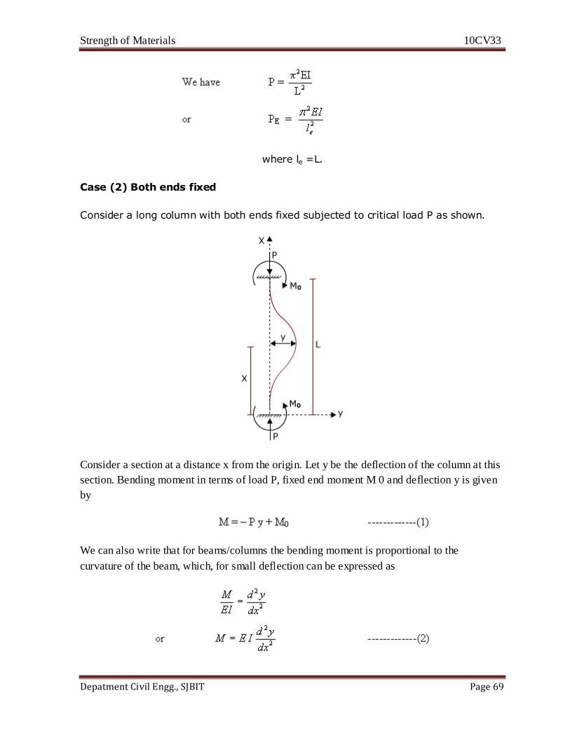
Strength of Materials 10CV33
Depatment Civil Engg., SJBIT Page 69
where le =L.
Case (2) Both ends fixed
Consider a long column with both ends fixed subjected to critical load P as shown.
Consider a section at a distance x from the origin. Let y be the deflection of the column at this
section. Bending moment in terms of load P, fixed end moment M 0 and deflection y is given
by
We can also write that for beams/columns the bending moment is proportional to the
curvature of the beam, which, for small deflection can be expressed as

Strength of Materials 10CV33
Depatment Civil Engg., SJBIT Page 70
where E is the Young's modulus and I is the moment of Inertia.
Substituting eq.(1) in eq.(2)
This is a second order differential equation, which has a general solution form of
where C1 and C2 are constants. The values of constants can be obtained by applying the
boundary conditions:
(i) y = 0 at x = 0. That is, the deflection of the column must be zero at near end since it is
fixed. Applying this condition (putting these values into the eq. (3)) gives us the following
result:
ii) At X = 0
=0, that is, the slope of the column must be zero, since it is fixed.
Substituting the boundary condition in eq. (4)
Substituting the constants C1 and C2 in eq. (3) leads to the following
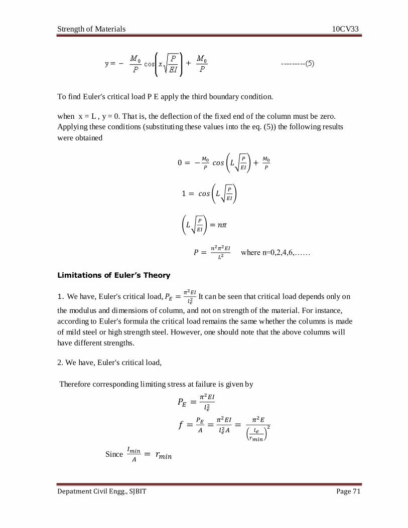
Strength of Materials 10CV33
Depatment Civil Engg., SJBIT Page 71
To find Euler's critical load P E apply the third boundary condition.
when x = L , y = 0. That is, the deflection of the fixed end of the column must be zero.
Applying these conditions (substituting these values into the eq. (5)) the following results
were obtained
where n=0,2,4,6,……
Limitations of Euler’s Theory
1. We have, Euler's critical load,
It can be seen that critical load depends only on
the modulus and dimensions of column, and not on strength of the material. For instance,
according to Euler's formula the critical load remains the same whether the columns is made
of mild steel or high strength steel. However, one should note that the above columns will
have different strengths.
2. We have, Euler's critical load,
Therefore corresponding limiting stress at failure is given by
Since

Strength of Materials 10CV33
Depatment Civil Engg., SJBIT Page 72
The variation of limiting stress ‘f' versus slenderness ratio
in the above equation is
shown below.
f
The above plot shows that the limiting stress ‘f' decreases as increases. In fact, when very
small, limiting stress is is close to infinity, which is not rational. Limiting stress cannot be
greater than the yield stress of the material.
3. Eulers formula determines the critical load, not the working load. Suitable factor of safety
(which is about 1.7 to 2.5) should be considered to obtain the allowable load.
Rankine's critical Load
Rankine Gordon Load is given by the following empirical formula,
This relationship is assumed to be valid for short, medium and long columns. This relation can
be used to find the load carrying capacity of a column subjected to crushing and/or buckling.
From eq. (1)
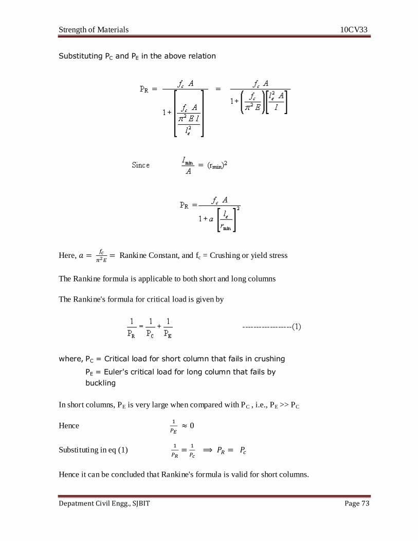
Strength of Materials 10CV33
Depatment Civil Engg., SJBIT Page 73
Substituting PC and PE in the above relation
Here,
Rankine Constant, and fc = Crushing or yield stress
The Rankine formula is applicable to both short and long columns
The Rankine's formula for critical load is given by
where, PC = Critical load for short column that fails in crushing
PE = Euler's critical load for long column that fails by
buckling
In short columns, PE is very large when compared with PC , i.e., PE >> PC
Hence
Substituting in eq (1)
Hence it can be concluded that Rankine's formula is valid for short columns.
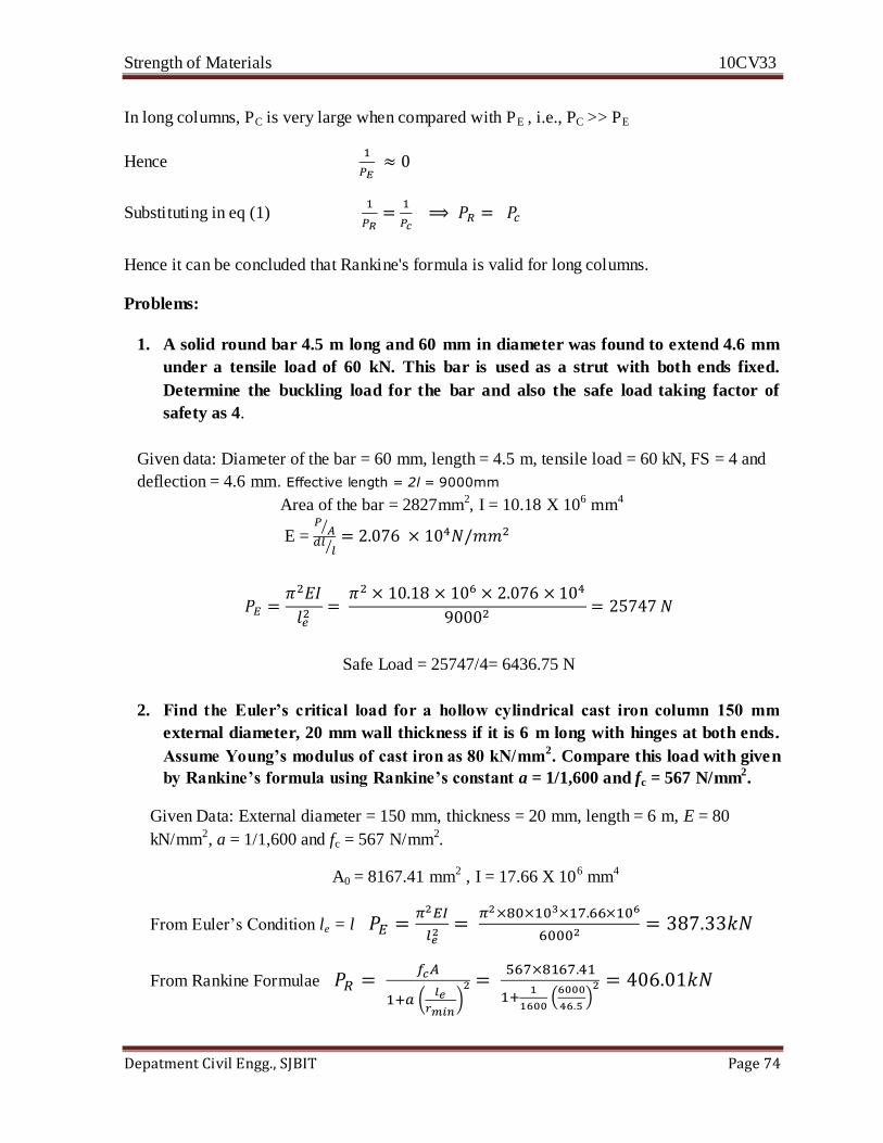
Strength of Materials 10CV33
Depatment Civil Engg., SJBIT Page 74
In long columns, PC is very large when compared with PE , i.e., PC >> PE
Hence
Substituting in eq (1)
Hence it can be concluded that Rankine's formula is valid for long columns.
Problems:
1. A solid round bar 4.5 m long and 60 mm in diameter was found to extend 4.6 mm
under a tensile load of 60 kN. This bar is used as a strut with both ends fixed.
Determine the buckling load for the bar and also the safe load taking factor of
safety as 4.
Given data: Diameter of the bar = 60 mm, length = 4.5 m, tensile load = 60 kN, FS = 4 and
deflection = 4.6 mm. Effective length = 2l = 9000mm
Area of the bar = 2827mm2, I = 10.18 X 106 mm4
E =
Safe Load = 25747/4= 6436.75 N
2. Find the Euler’s critical load for a hollow cylindrical cast iron column 150 mm
external diameter, 20 mm wall thickness if it is 6 m long with hinges at both ends.
Assume Young’s modulus of cast iron as 80 kN/mm2. Compare this load with given
by Rankine’s formula using Rankine’s constant a = 1/1,600 and fc = 567 N/mm2.
Given Data: External diameter = 150 mm, thickness = 20 mm, length = 6 m, E = 80
kN/mm2, a = 1/1,600 and fc = 567 N/mm2.
A0 = 8167.41 mm2 , I = 17.66 X 106 mm4
From Euler’s Condition le = l
From Rankine Formulae