strategies for concurrent processing complex algorithms in data driven ... · strategies for...
TRANSCRIPT

NASA Contractor Report 181657
. STRATEGIES FOR CONCURRENT PROCESSING OF COMPLEX ALGORITHMS I N DATA DRIVEN ARCHITECTURES
John W . S t o u g h t o n and R o l a n d R. M i e l k e
OLD DOMINION U N I V E R S I T Y RESEARCH FOUNDATION N o r f o l k , V i r g i n i a
( W B S P C B - 18 16 57) PROCESSING OF COXPLEX ALGORITHHS IN DATA D R I V E N ARCHITECTURES (Old Dominion U n i v . ) 7 3 p C S C L J 9 C Unclas
STR A T E G I E S FOR CONC U RR EN l? N88-23C83
G 3 / 3 3 0145915
G r a n t N A G 1 - 6 8 3 February 1988
.
National Aeronautics and Space Administration
Langley Research Center Hampton, Virginia 23665
https://ntrs.nasa.gov/search.jsp?R=19880013699 2018-06-02T11:18:49+00:00Z

TABLE OF CONTENTS
Page
CHAPTER
1.0 INTRODUCTION . 0
2.0 ATAMM MODEL DEVELOPMENT ...................................
3.0
2.1 I n t r o d u c t i o n ..................................... 2.2 Problem Desc r ip t i on .............................. 2.3 Algo r i t hm D i rec ted Graphs ........................ 2.4 P e t r i Nets and Marked Graphs ..................... 2.5 Algo r i t hm Marked Graph ........................... 2.6 Computational environment..............^....*...*
2.7 Computational Marked Graph ....................... GRAPH MODEL OPERATING CHARACTERISTICS .....................
3.1 I n t r o d u c t i o n ..................................... 3.2 S t a t e Equat ion Desc r ip t i on ....................... 3.3 Marked Graph Proper t i es .......................... 3.4 A n a l y t i c a l Bounds on Computational Performance ...
4.0 PROTOTYPE ARCHITECTURE .................................... 4.1 I n t r o d u c t i o n ..................................... 4.2 Proto type Overview ............................... 4.3 Proto type Graph Manager .......................... 4.4 Proto type Func t iona l U n i t ........................ 4.5 Proto type Global Memory .......................... 4.6 Synthesis Considerat ions .........................
1
4
4
5
8
9
11
13
19
23
23
23
26
31
34
34
34
35
37
39
39
i

TABLE OF CONTENTS- continued
5.0 EXPERIMENTAL EVALUATION .................................... 5.1 I n t roduc t i on ...................................... 5.2 System Diagnost ics ................................
6.0 CONCLUSIONS AND FUTURE DIRECTIONS .......................... HEFERENCES ...................................................... BIBLIOGRAPHY .................................................... APPENDIX A: PETRI NET BACKGROUND ............................... APPENDI x B: PUBLICATIONS AND PRESENTATIONS .....................
LIST OF FIGURES
Figure
2 . 1 Algor i thm t o a r c h i t e c t u r e mapping problem ................ 2.1 Funct ional correspondence ................................ 2.2 Algor i thm d i r e c t e d graph-decomposed s t a t e equat ion ....... 2.3 Marked o rd ina ry P e t r i n e t ................................ 2.4 Algor i thm Marked Graph-decomposed s t a t e equat ion ......... 2.5 Candidate a r c h i t e c t u r e ................................... 2.6 Node marked graph 3-node model ........................... 2.7 Node marked graph one-node model ......................... 2.8
2.9 Re la t iona l diagram o f ATAMM model ........................ 3.1 Performance Bounds .......................................
Computational Marked Graph o f Decomposed State Equation ..
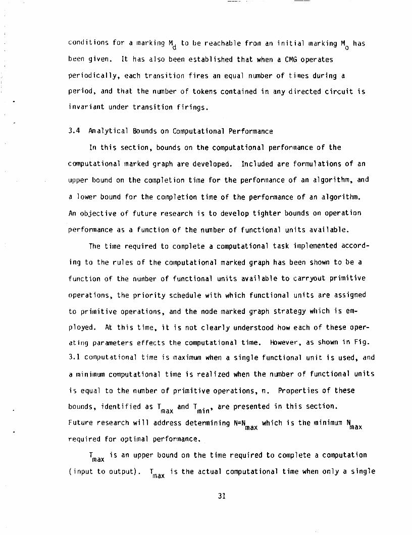
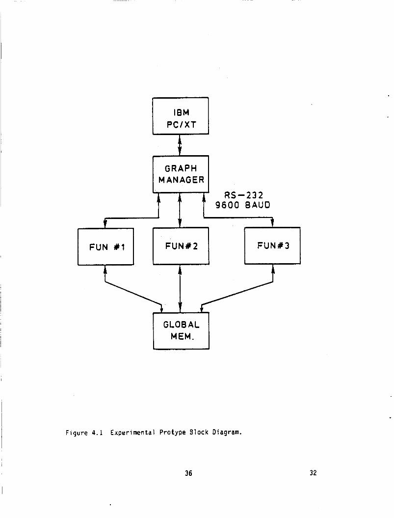
4.1 Experimental Protype Block Diagram ....................... 4.2 S i m p l i f i e d Graph Manager c o n t r o l s t a t e s .................. 4.3 Funct ional Un i t Control .................................. 4.4 Global Memory Control Diagram ............................ 4.5 Expanded Read Node Marked Graph ..........................
ii
Page
46
46
46
56
58
59
64
67
Page
2
6
10
1 2
1 4
1 6
1 9
19
20
2 2
32
36
38
40
4 1
43

.
TABLE OF COIITENTS . concluded
LIST OF FIGURES . concluded
F i gure
4.6 Prototype Communication Dialogue ......................... 4.7 Expanded Node Marked Graph (NMG) .......................... 5.1 Analyzer's Node A c t i v i t y Display, Assigned FU's .......... 5.2 Read/Process/Write Node A c t i v i t y ......................... 5.3 Enlargement o f Read/Process/Write Display ................ 5.4 FUN A c t i v i t y ............................................. 5.5 Timing Analysis Display .................................. 5.6 Analyzer's Concurrency Display ...........................
Page
44
4 5
48
50
51
5 2
53
55
iii

CHAPTER 1
1.0 INTRODUCTION
This r e p o r t presents t h e r e s u l t s o f ongoing research d i r e c t e d a t deve l -
oping a graph t h e o r e t i c model f o r desc r ib ing da ta and c o n t r o l f l o w associ-
ated w i t h t h e execut ion o f l a r g e grained a lgor i thms i n a spec ia l d i s t r i b u t e d
computer environment.
represents - Algor i thm - - To Arch i tec tu re - Mapping - Model.
inodel i s t o p rov ide a b a s i s f o r e s t a b l i s h i n g r u l e s f o r r e l a t i n g an a lgo r i t hm
t o i t s execut ion i n a mul t iprocessor environment. S y n b o l i c a l l y t h i s problem
i s i l l u s t r a t e d i n F igu re 1.1
Th is model i s i d e n t i f i e d b y t h e acronyn ATAMM which
The purpose of such a
Specif c a t i o n s de r i ved from t h e model l ead d i r e c t l y t o t h e d e s c r i p t i o n
o f a da ta f ow a r c h i t e c t u r e which i s a consequence o f t h e i nhe ren t behavior
o f t he da ta and c o n t r o l f l o w descr ibed b y t h e model. The purpose o f t h e
ATAMM based a r c h i t e c t u r e i s t o op t im ize computational concurrency i n t h e
inul t i processor environment and t o p rov ide an a n a l y t i c a l b a s i s f o r perfor-
mance eva lua t ion . The ATAMM model and a r c h i t e c t u r e s p e c i f i c a t i o n s are dem-
ons t ra ted on a p ro to type system f o r concept v a l i d a t i o n .
The problem domain o f t h e research repo r ted he re in Consis ts o f dec i s ion
f r e e algor i thms w i t h cornputat ional ly complex p r i m i t i v e operat ions which a r e
assumed t o be implemented i n a dedicated d i s t r i b u t e d mult icomputer env i ron-
ment. The algor i th,ns a re such as may be found i n ( b u t n o t l i m i t e d t o ) l a r g e
1

RULES???
ALGORITHM GRAPH CONCURRENT PROCESSING ARCHITECTURE
Fiqure 1.1 A l g o r i t h m t o architecture mapping probleiri.
2

scale s i yna l processing and c o n t r o l app l i ca t ions .
cessor environment i s assumed t o cons is t o f 2 t o 20 processing elements f o r
concurrent. execut ion o f the var ious a lgor i th ln p r i i n i t i v e s . Fur ther , Very
High Speed In tegra ted C i r c u i t (VHSIC) technology i nco rpo ra t i ng t h e MIL-STD
1 7 W A i n s t r u c t i o n se t i s t h e intended technology f o r t h e support o f t h e
mul t iprocessor environment.
The an t i c ipa ted mul t ip ro -
From t h e g iven problem domain, t h e research products a re t h e r e s u l t o f
understanding two major areas.
sor a rch i tec tu res and P e t r i - n e t and marked graph theo ry which prov ides t h e
t h e o r e t i c a l b a s i s f o r t h e ATAMM model.
These areas are non Von Neumann mul t iproces-
Chapter 2 presents t h e ATAMM model development. From the model des-
c r i p t i o n , general s p e c i f i c a t i o n s of a da ta f low arch i t e c t i i r e are generated.
Chapter 3 presents an i n t r o d u c t o r y d iscuss ion o f performance measures.
Chapter 4, a da ta f l o w pro to type o f a mul t iprocessor a r c h i t e c t u r e design
based on t h e ATAMM s p e c i f i c a t i o n s i s described.
I n
Implelnentation o f t h i s
on o f t h e ATAMN Model r u l e s .
r e s u l t s f rom t h e da ta f l o w
d i r e c t i o n o f t h e research.
The use o f brand names i n t h i s document i s f o r completeness and
does n o t imp ly NASA endorsement.
p ro to type prov ides experimenta
Chapter 5 presents p r e l i in inary
prototype. Chapter 6 o u t l i n e s
v e r i f i c a t
eval ua t i o n
t h e f u t u r e
3

CHAPTER 2
2.0 ATAm MOOEL DEVELOPMENT
2.1 In t roduc t i on
New computer a rch i tec tu res based upon mu1 t i p l e processor o rgan iza t ions
f o r coinputation are mot ivated main ly b y t h e d e s i r e t o increase computer
performance through the use o f concurrency f o r computational l y i n t e n s i v e
appl i ca t i ons . The development o f p a r a l l e l a rch i tec tu res composed o f
ident ica l , ' spec ia l purpose computing elements i s a l ready a t o p i c o f g rea t
i n t e r e s t t o inany researchers.
o f a lyor i thms i n t h i s s e t t i n g do n o t appear t o be adequate t o address t h e
complex issues o f scheduling, coord ina t ion , and communication.
However, models f o r descr ib ing t h e behavior
I n t h i s chapter, a modeling process t o descr ibe concurrent processing
o f decomposed a lgor i thms i s presented. The r e s u l t i n g model (ATAMM) cons is t s
o f a P e t r i ne t marked graph which incorpora tes general s p e c i f i c a t i o n s of
coininunication and processing associated w i t h each computational event i n a
mul t iprocessor da ta f l o w a rch i tec tu re .
process i s impor tant f o r t w o reasons. F i r s t , t h e model p rov ides a hardware-
independent context i n which t o i n v e s t i g a t e t h e r e l a t i v e m e r i t s o f d i f f e r e n t
a lgor i thm decomposition and implementat ion s t ra teg ies .
c l e a r l y d i sp lays t h e da ta f l o w and c o n t r o l f l o w which must be manifested b y
any da ta f low computer a r c h i t e c t u r e implementing t h e decomposed algor i thm.
Thus the ATAMM Model prov ides the foundat ion f o r t h e development o f design
procedures f o r concurrent processing o f complex a l g o r i t h m .
The a v a i l a b i l i t y o f such a inodeling
Second, t h e model
I n Section 2.2, a d e s c r i p t i o n o f t h e c l a s s o f problems under considera-
t i o n i s given. The d i r e c t e d graph representa t ion o f p a r t i c u l a r decomposed
4

algor i thms i s described i n Sect ion 2.3. A f t e r a b r i e f i n t r o d u c t i o n t o
P e t r i - n e t and marked graphs i n Sections 2.4 and 2.5, t h e bas ic assumptions
concerning the a r c h i t e c t u r a l environment are presented i n Sect ion 2.6. The
development of t he computational marked graph model i n Sect ion 2.7 completes
the ATAMM model development.
2.2 Problem Desc r ip t i on
The computational problems of i n t e r e s t are dec i s ion - f ree computation-
a l l y complex problems as are o f t e n found i n s igna l processing and c o n t r o l
app l i ca t i ons .
f unc t i on g iven by t h e t r i p l e ( X , Y , F ) .
m i s s i b l e inputs , Y represents the set o f admissible outputs, and F:X + Y i s
t he r u l e o f correspondence which unambiguously assigns e x a c t l y one element
from X t o each element of Y . This f u n c t i o n a l problem statement i s i l l u s -
t r a t e d i n F igu re 2.1.
r i th in .
operat ions and operands which represent t h e p a r t i c u l a r r u l e of correspon-
tlence F : X + Y.
A problem d e s c r i p t i o n normal ly r e s u l t s i n the d e f i n i t i o n of a
The se t X represents the s e t of ad-
Associated w i t h a computational problem i s an alga-
An a lgo r i t hm i s composed o f a s e q u e n t i a l l y ordered se t of p r i m i t i v e
A g iven problem o f t e n decomposes i n t o a number o f d i f f e r e n t a l g o r i t h m .
I n general, a g iven a lgo r i t hm can be decomposed by several d i f f e r e n t p r i m i -
t i v e operator sets.
of t en d i f f e r e n t sequences o f p r i m i t i v e operat ions which can be scheduled t o
c a r r y o u t t h e algor i thm. For i l l u s t r a t i o n , consider t h e f o l l o w i n g problem.
Suppose t h a t Y = X i s t h e se t o f (nxn) matr ices w i t h elements i n R ( s e t of
r e a l nunbers.) 2
y E Y g iven by y = f ( x ) = x
i r ia l r ices w i t h elements i n R .
Also, f o r a given p r i m i t i v e operator set , t h e r e are
Given a m a t r i x x E n, i t i s des i red t o compute a m a t r i x
+ ax + b where a and b are s p e c i f i e d (nxn)
This a lgo r i t hm can be decomposed i n the two
5

f: x -Y
tasks -function
Figure 2.1 Functional correspondence.
6

s e t s o f p r i m i t i v e opera tors s ta ted below.
P r i m i t i v e Operator Set One:
and
P r i m i t i v e Operator Set Two
f3(p,q,r) = ( P 9) + r *
Using p r i m i t i v e operator s e t one, t h e a lgor i thm i s represented by two
d i f f e r e n t opera tor sequences:
y = f ( x ) = { [ ( x x ) + ( a x ) ] + b)
= flI fl[f2(X’& f2(a,x)l,b1,
o r
y = f ( x ) = { [x ( x + a ) ] + b)
= flt f2[x,f1(x,a), b)
Another decomposition i s expressed us ing p r i m i t i v e ope ra t i ve s e t two:
where t h e n o t a t
y = f ( x ) = { x [(l x) + a] + b)
= f31x, f3[1,a,xl, b)
on 1 i s used t o represent t h e (nxn) i d e n t t y ma t r i x .
7

2.3 A1 g o r i thm D i rec ted Graph
An a lgor i thm d i r e c t e d graph (ADG) i s a d i r e c t e d graph which represents
The graph prov ides a d e s c r i p t i o n o f t he a r p e c i f i c a lgor i thm decomposition.
operand da ta f low and opera t ion sequence requ i red by t h e a lgor i thm
decomposition.
each occurence o f a p r i m i t i v e operat ion.
edge ( i , j ) d rec ted froin ver tex i t o ve r tex j i f t h e ou tpu t o f p r i m i t i v e
opera t ion i s an i n p u t operand f o r p r i m i t i v e opera t ion j.
cons t ruc t i ng an a lgor i thm graph, v e r t i c e s ( p r i m i t i v e operat ions) a re
d isp layed as c i r c l e s , and edges ( i npu t -ou tpu t s igna ls ) a re d isp layed as
d i rec ted l i n e segments connect ing appropr ia te v e r t i c e s . Sources and s inks
fo r i npu t and output s igna ls a re represented as squares.
constants are no t i i s u a l l y inc luded i n t h e a lgor i thm graph; however,
t r i a n g l e s are used f o r t h i s purpose when necessary.
Ver t ices o f the ADG are i n a one-to-one correspondence w i t h
The a lgor i thm graph conta ins an
When
Sources froin
To i l l u s t r a t e the cons t ruc t i on o f an a lgo r i t hm d i r e c t e d graph, cons ider
the problem o f computing t h e ou tpu t o f a d i s c r e t e l i n e a r system g iven a
sequence o f i npu ts t o t h e system.
p a r t i t i o n e d s t a t e equat ion
Let t h e system be descr ibed by t h e
and
8

where x1 i s a p-vector, x i s a q-vector, u i s an m-vector, y i s an r-vec-
t o r , p + q = n, and Aij and Bk are constant submatrices. The p r i m i t i v e
operat ions are def ined as m a t r i x m u l t i p l i c a t i o n and vec tor add i t ion , and t h e
na tu ra l a lgor i thm decomposition r e s u l t i n g f rom the s t a t e equat ion descr ip -
t i o n i s selected.
r i t h m i s shown i n F ig . 2.2. Note t h a t each edge i s labe led w i th t h e corre-
sponding da ta and t h e nodes are labe led t o i n d i c a t e t h e associated computa-
t iona l operat ion.
2
The a lgor i thm d i r e c t e d graph f o r t h i s decomposed algo-
2.4 P e t r i Nets and Marked Graphs
P e t r i ne ts have been es tab l i shed as an appropr ia te model f o r descr ib-
i ng o r c o n t r o l 1 i n g systems def ined by some sequence o f events. Without
argument, t h e a lgor i thm d i r e c t e d graph s a t i s f i e s t h i s general aspect. Fur-
t he r , s ince computers need t o communicate and be c o n t r o l l e d on t h e occurence
o f c e r t a i n events, t h e P e t r i n e t becomes a s u i t a b l e t o o l t o form the bas i s
of t he ATAMM model.
lems under cons idera t ion lead t o a s i m p l i f i e d P e t r i ne t representat ion.
(For a formal d e s c r i p t i o n o f P e t r i n e t features, t h e reader i s r e f e r r e d t o
Appendix A.)
Cer ta in phys ica l c h a r a c t e r i s t i c s o f t h e c lass o f prob-
Consider ing t h e da ta f l o w i n an a lgor i thm d i r e c t e d graph, t h e execut ion
o f a p r i m i t i v e opera t ion i s precondi t ioned on t h e a v a i l a b i l i t y of i n p u t
s i g n a l s ( o r operands).
" t r a n s i t i o n " which is "enabled" f o r " f i r i n g " when i n p u t "places" t o t h e
t r a n s i t i o n are marked w i t h "tokens". Because t h e s igna l o r da ta a v a i l a b i l -
i t y i s a b i n a r y cond i t ion , i t i s appropr ia te t h a t t h e tokens are l i m i t e d t o
t h e s e t (0,l) i n order t o associate p laces (cond i t ions) t o t ransac t i ons
(events) i n a b i n a r y way. A P e t r i n e t having such r e s t r i c t e d i n p u t and
Th is process may be d i r e c t l y modeled by a P e t r i - n e t
9

L X 0 -0
x C cn .-
*
- L J 0 m
c 0
N
10
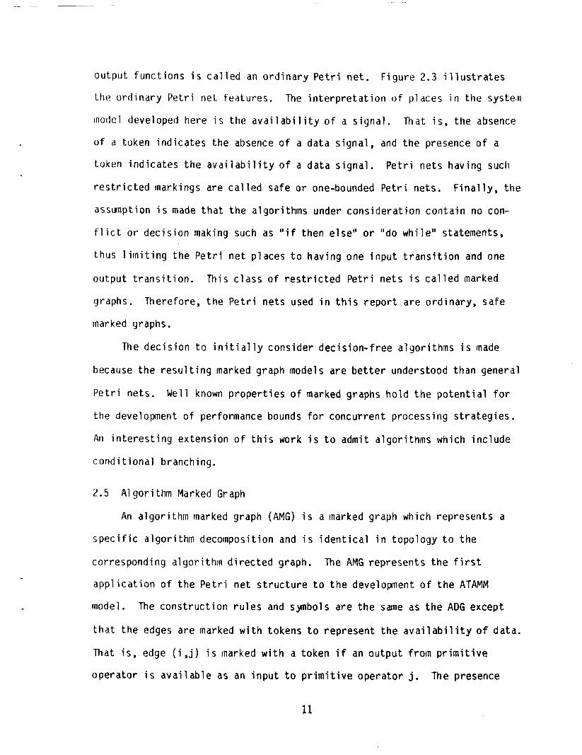
output func t ions i s c a l l e d an o r d i n a r y P e t r i n e t .
I.he o rd ind ry P e t r i net. features.
model developed here i s t h e a v a i l a b i l i t y o f a s igna l ,
o f d token ind i ca tes t h e absence o f a data s igna l , and t h e presence of a
token ind i ca tes t h e ava l a b i l i t y o f a da ta s igna l .
r e s t r i c t e d markings are c a l l e d safe o r one-bounded P e t r i nets .
assunpt ion i s made t h a t t h e a lgor i thms under cons idera t ion con ta in no con-
f l i c t o r dec i s ion making such as "if then e lse" o r "do wh i l e " statements,
F igure 2.3 i l l u s t r a t e s
The i n t e r p r e t a t i o n o f p ldces i n the systeln
That i s , t h e absence
P e t r i ne ts having such
F i n a l l y , t h e
thus l i m i t i n g t h e P e t r i n e t p laces t o hav ing one i n p u t t r a n s i t i o n and one
output t r a n s i t i o n . This c l a s s o f r e s t r i c t e d P e t r i ne ts i s c a l l e d marked
graphs. Therefore, t h e P e t r i ne ts used i n t h i s r e p o r t a re o rd ina ry , safe
marked graphs.
The dec i s ion t o i n i t i a l l y cons ider dec is ion- f ree a l g o r i t h m i s made
because t h e r e s u l t i n g marked graph models a re b e t t e r understood than general
P e t r i ne ts .
the development o f performance bounds f o r concurrent processing s t ra teg ies .
An i n t e r e s t i n g extens ion o f t h i s work i s t o admit a l g o r i t h m which i nc lude
cond i t i o n a l branching.
Well known p r o p e r t i e s o f marked graphs h o l d t h e p o t e n t i a l f o r
2.5 A lgor i thm Marked Graph
An a lgor i thm marked graph (AMG) i s a marked graph which represents a
s p e c i f i c a lgor i thm decomposition and i s i d e n t i c a l i n topology t o t h e
corresponding a lgor i thm d i r e c t e d graph.
a p p l i c a t i o n o f t h e P e t r i n e t s t r u c t u r e t o t h e developnent o f t h e ATAMM
model.
t h a t t h e edges a re marked w i t h tokens t o represent t h e a v a i l a b i l i t y o f data.
That i s , edge ( i , j ) i s marked w i t h a token i f an ou tpu t f rom p r i m i t i v e
opera tor i s a v a i l a b l e as an i n p u t t o p r i m i t i v e opera tor j.
The AMG represents t h e f i r s t
The cons t ruc t i on r u l e s and synbols are t h e same as t h e ADG except
The presence
11

I
PETRI NET REPRESENT
MARKED GRAPH REPRESENTATION
Figure 2 . 3 Marked ordinary Petri net.

t irne
2.6
; n u l t
of a token on an edge i s ind ica ted by a s o l i d d o t placed on t he edge.
v e r t i c e s corrcsporid t o t r a n s i t i o n s which may f i r e a f t e r be ing enabled b y the
a v a i l a b i l i t y o f a l l i npu t da ta tokens.
The
The decomposed s t a t e equat ion represented i n F i g . 2.2 i s used t o
i l l u s t r a t e t h e AMG. The example AMG i s shown i n Fig. 2.4. It should be
noted t h a t t he i n i t i a l cond i t i ons f o r t h e recu rs ion are represented b y
tokens on t h e l oop edges.
The a lgor i thm marked graph i s a useful t o o l f o r represent ing decomposed
a lgor i thms and f o r d i s p l a y i n g da ta f l o w w i t h i n an a lgor i thm.
AMG does n o t d i s p l a y procedures t h a t a computing s t r u c t u r e must mani fest i n
order t o perform the computing task.
However, t h e
I n add i t ion , t h e issues o f c o n t r o l ,
performance, and resource inanaganent a re n o t apparent i n t h i s graph.
Co m p u t a t i o n a 1 En v i r o ninen t
The computational environment f o r
processor da ta - f l ow computer arch
the ATAMM model i s assuned t o be a
tec tu re . The da ta f l o w aspect i s
mot ivated b y the a lgor i thm d i r e c t e d graph which de f ines t h e da ta f low
requ i red t o execute the algor i thm.
The a r c h i t e c t u r e i s assuned t o c o n s i s t o f R i d e n t i c a l processors o r
f unc t i ona l u n i t s (FUNs) where R has a va lue i n t h e range o f two t o twenty.
This upper bound i s suggested f o r p r a c t i c a l reasons due t o t h e l a r g e gra ined
a5pect o f t he a lgor i thm decomposition and t h e need t o ma in ta in communication
t iines sinal 1 re1 a t i v e t o process t imes.
f o r access t o communication paths occurs between f u n c t i o n a l u n i t s .
Therefore, 1 i t t l e o r no conten t ion
Each FUN i s a processor having l o c a l rnemory f o r program storage and
temporary i npu t and ou tpu t da ta conta iners.
execute any a l g o r i t h m p r i m i t i v e operat ion.
Each FUN has t h e c a p a b i l i t y t o
The FUNs share a comon g loba l
13

c 0 .C
U aJ Y L
9
c U
14

memory (GLM) which may be e i t h e r c e n t r a l i z e d o r d i s t r i b u t e d .
coord ina t ion o f FUNS i n r e l a t i o n t o da ta and c o n t r o l f l o w i s d i r e c t e d b y t h e
graph manager (GRM).
The
The GRM i t s e l f may be c e n t r a l i z e d o r d i s t r i b u t e d .
Output created b y t h e complet ion o f a p r i m i t i v e opera t ion i s placed
i n t o g loba l memory o n l y a f t e r t h e ou tpu t da ta conta iners have been emptied.
That i s , outputs must be consumed as i n p u t s t o successor p r i m i t i v e
operat ions before a l low ing new data t o f i l l t h e output l o c a t i o n s .
Assignment o f a f u n c t i o n a l u n i t t o a s p e c i f i c a lgor i thm p r i m i t i v e
opera t ion i s made b y t h e GRM o n l y when a l l i n p u t s r e q u i r e d b y t h e opera t ion
are a v a i l a b l e i n g loba l memory and a f u n c t i o n a l u n i t i s ava i lab le .
feature t h a t w i l l be developed l a t e r i s t h a t assignment o f f u n c t i o n a l u n i t s
t o p r i m i t i v e operat ions i s performed cont inuous ly dur ing run- t ime execut ion
o f t h e algor i thm.
i n which p r i m i t i v e operat ions are assigned t o s p e c i f i c f u n c t i o n a l u n i t s
d u r i n g program d e v e l o p e n t , and w i t h dynamic resource assignment procedures
i n which p r i m i t i v e operat ions are assigned t o s p e c i f i c f u n c i t o n a l u n i t s
d u r i n g program compi lat ion.
cons is ten t w i t h these assumptions i s shown i n F ig . 2.5.
o f an experimental prototype a r c h i t e c t u r e are descr ibed i n Chapter 4.
A
This c o n t r a s t s w i t h s t a t i c resource assignment procedures
One o f many poss ib le computer a r c h i t e c t u r e s
Speci f ic features
Algor i thm requirements and t h e computing environment may now be
i n t e g r a t e d i n t o a comprehensive P e t r i n e t model t o complete t h e ATAMM model.
The model c o n s i s t s of a P e t r i n e t marked graph c a l l e d t h e computational
marked graph (CMG).
requ i red t o implement a decomposed a lgor i thm i n a mul t iprocessor da ta f l o w
computer a rch i tec tu re .
an in termediate graph c a l l e d t h e node marked graph (NMG).
The CMG d i s p l a y s t h e d a t a f l o w and c o n t r o l low
Before d e f i n i n g t h i s model, i t i s h e l p f u t o de f ine
15

FUN # 1 w I -- G R A P H
MANAGER
f
FUN # 2 I
i
0 0 v
7 GLOBAL 1 MEMORY
t FUN #n
F i g u r e 2.5 Candidate architecture.
16

The NMG represents the computing a c t i v i t i e s o f execut ing a p r i m i t i v e
opera t ion by a func t i ona l u n i t . Three pr imary a c t i v i t i e s , reading o f i n p u t
da ta from g loba l memory, processing o f i n p u t da ta t o compute an output, and
w r i t i n g o f output data t o g loba l memory, are represented as t r a n s i t i o n s
( v e r t i c e s ) i n the NMG.
places (edges), and the presence o f s igna ls i s notated b y tokens marking
appropr ia te edges. The cond i t i ons f o r f i r i n g t h e process and w r i t e
t r a n s i t i o n s o f t he NMG are as def ined f o r a general P e t r i net , wh i l e t h e
read t r a n s i t i o n has one a d d i t i o n a l cond i t i on f o r f i r i n g . In a d d i t i o n t o
having a token present on each incoming s igna l edge, a f u n c t i o n a l u n i t must
be a v a i l a b l e f o r assignment t o t h e p r i m i t i v e opera t ion be fore t h e read node
can f i r e .
process, and w r i t e operat ions be fore being re tu rned t o a queue of a v a i l a b l e
FUNS.
Data and c o n t r o l f l o w paths are represented as
Once assigned, t h e f u n c t i o n a l u n i t i s used t o implement t h e read,
Two d i f f e r e n t node marked graphs are de f ined t o represent t w o d i f f e r e n t
s t ra teg ies .
c o n t r o l s igna ls i n d i c a t i n g t h a t empty da ta conta iners are a v a i l a b l e t o
rece ive new output are i npu t edges t o the w r i t e t r a n s i t i o n . Therefore,
i n i t i a t i o n of t h e p r i m i t i v e opera t ion depends on ly on a v a i l a b l i t y o f i n p u t
da ta and a v a i l a b i l i t y o f a f u n c t i o n a l u n i t .
p r i m i t i v e opera t ion t o commence w i thout f i r s t having an ou tpu t con ta iner
a v a i l a b l e i n g loba l memory. This model i s shown i n F ig . 2.6. The second
model, c a l l e d t h e one node model, requ i res c o n t r o l s igna ls i n d i c a t i n g t h a t
empty da ta conta iners are a v a i l a b l e t o rece ive new outpu t as i n p u t edges t o
The f i r s t mode, c a l l e d the th ree node model, requ i res t h a t
This s t r a t e g y a l lows a
t h e read t r a n s i t o n . Therefore, i n i t i a t i o n o f t h e p r i m i t i v e opera t ion
requ i res n o t o n l y the a v a i l a b i l i t y o f i n p u t da ta and a f u n c t i o n a l u n i t , b u t
17

Figure 2 . 6 Node marked graph 3-node model.
Figure 2 . 7 Node marked graph one-node model.
18

a lso the a v a i l a b i l i t y o f empty ou tpu t da ta conta iners i n g loba l memory.
This model i s shown i n Fig. 2.7. It i s noted t h a t t he th ree node inodel i s
used i n most o f the exanples o f t h i s r e p o r t .
observed t h a t the one node model has the inherent p roper t y o f ma in ta in ing
deadlock f r e e CMG graphs. Tnus, i t i s an t i c ipa ted t h a t the one node NMG
w i l l become prominent i n f u t u r e development and appl i c a t i o n o f t h e ATAMM
model.
However, i t has been r e c e n t l y
2.7 Computational Marked Graph
A computational marked graph (CMG) i s const ructed from an a lgor i thm
marked graph according t o the f o l l o w i n g r u l e s .
1. Source and s ink nodes i n t h e a lgor i thm graph are represented b y
source and s ink nodes i n the CMG.
Nodes corresponding t o p r i m i t i v e opera t ions i n t h e a lgo r i t hm graph
a re represented by NMGs i n t h e CMG.
Edges i n the a lgor i thm graph are represented b y edge pa i rs , one
forward d i r e c t e d f o r da ta f l o w and one backward d i r e c t e d f o r
c o n t r o l f low, i n the CMG.
2.
3.
The p l a y o f t he CMG proceeds according t o the f o l l o w i n g graph r u l e s .
1) A node i s enabled when a l l incoming edges are marked w i t h a token.
An enabled node f i r e s b y encunbering one token f r o m each incoming
edge, de lay ing f o r sane s p e c i f i e d t r a n s i t i o n time, and then
depos i t i ng one token on each outgoing edge.
A source node and a s i n k node f i r e when enabled w i thout regard f o r
t h e a v a i l a b i l i t y o f a FUN.
A p r i m i t i v e ope ra t i on i s i n i t i a t e d when t h e read node o f an NMG i s
enabled and a FUN i s a v a i l a b l e f o r assignment t o t h e NMG and thus
f i r e s t h e read node,
2)
3 )
A FUN remains assigned t o an NMG u n t i l
19

20

complet ion o f t h e f i r i n g o f t h e w r i t e node o f t h e NMG.
of t h i s l o g i c a l assignment o f t h e FUN i s managed b y t h e GRM.
Supervision
I n order t o i l l u s t r a t e t h e cons t ruc t i on o f a computational marked
graph, the CMG corresponding t o t h e a lgor i thm graph o f Fig. 2.2 i s shown i n
Fig. 2.8. The th ree node NMG i s used i n t h i s CMG f o r convenience o f
presentat ion.
c l e a r l y d i sp lays t h e da ta and c o n t r o l f l o w which must occur i n any hardware
implementation o f t h e model process, and because i t provides a hardware
independent contex t i n which t o evaluate process performance.
becomes the t h e o r e t i c a l v e h i c l e f o r present ing t h e ATAMM model.
The computational marked graph i s important because i t
Thus, t h e CMG
The ATAMM model cons i s t s o f a l l t h e modeling steps which l ead t o t h e
i n t e g r a t i o n o f t h e a lgor i thm data f l o w w i t h t h e da ta f l o w arch i tec tu re .
p i c t o r i a l d e s c r i p t i o n o f t h e ATAMM model i s shown i n Fig. 2.9.
A
21

4 ALGO RI TH M I DIRECTED I
I
22

CHAPTER 3
3.0 6RAPH MOEL OPERATING CHARACTERISTICS
3.1 I n t r o d u c t i o n
An important component o f t h e ATAMM model, as p r e v i o u s l y described, i s
t h e CMG a lgor i thm/arch i tec tu re behaviora l model. Th is model i s impor tant
because i t prov ides a hardware independent contex t i n which t o i n v e s t i g a t e
t h e r e l a t i v e m e r i t s o f d i f f e r e n t a lgor i thm decompositions and d i f f e r e n t
implementation s t ra teg ies .
model a re s tud ied a n a l y t i c a l l y t o determine graph opera t ing c h a r a c t e r i s t i c s
and t o develop bounds on computational performance. Many o f t h e p r o p e r t i e s
presented here r e s u l t from r e s t r i c t i n g t h e a lgor i thms under cons idera t ion t o
be dec is ion- f ree so t h a t t h e graph models are marked graphs.
extens ion o f t h i s work i s t o conduct a s i m i l a r study admi t t ing a lgor i thms
conta in ing dec is ion p o i n t s (branching).
I n t h i s chapter, p r o p e r t i e s of t h e CMG P e t r i n e t
An impor tant
I n Sect ion 3.2, a s t a t e v a r i a b l e d e s c r i p t i o n i s developed f o r t h e com-
pu ta t i o n a l marked graph (CMG) . This fo rmula t ion expresses t h e nex t graph
marking as a f u n c t i o n o f t h e present marking and a vec tor which i n d i c a t e s
which t r a n s i t i o n i s t o be f i red. Graph operat ing c h a r a c t e r i s t i c s a r e de-
veloped a n a l y t i c a l l y i n Sect ion 3.3. Anong t h e p r o p e r t i e s considered a r e
r e a c h a b i l i t y , 1 iveness and safeness. Then, i n Section 3.4, performance
bounds are inves t iga ted .
estab l ished.
Upper and lower bounds f o r computational t i m e are
3.2 S ta te Equation Descr ip t ion
I n t h i s sect ion, a s t a t e equat ion fo rmula t ion f o r computing t h e marking
vec tor o f a marked graph i s presented.
t o general P e t r i nets .
Th is developnent i s e a s i l y extended
Let G be a marked graph c o n s i s t i n g o f m places and n
23

t r a n s i t i o n s .
f i r i n g o f some sequence o f k t r a n s i t i o n s .
The in-vector Mk i s t h e marking vec to r f o r G r e s u l t i n g f rom t h e
The f o l l o w i n g two d e f i n i t i o n s a re
necessary f o r t h e s t a t e equat ion fo rmula t ion .
Complete incidence Mat r ix . The coinplete inc idence m a t r i x f o r a marked graph
G i s the (nxin) m a t r i x A = [a . .] having rows corresponding t o t r a n s i t i o n s and 1J
columns corrc:l;ponding t o places, and where
q - 1 ) i f p lace j i s i n c i d e n t a t t r a n s i t i o n i and
d i r e c t e d o u t o f ( i n t o ) t he t r a n s i t i o n
i f p lace j i s n o t i n c i d e n t a t t r a n s i t i o n i.
Elementary F i r i n g Vector. An elementary f i r i n g vec to r uk i s an n-vector
having a l l zero e n t r i e s except f o r t h e i t h component which i s 1 denot ing
t h a t t r a n s i t i o n i i s t h e k t h t r a n s i t i o n t o f i r e i n soine t r a n s i t i o n f i r i n g
sequence.
To ga in i n s i g h t t o t h e s t a t e equat ion for inu lat ion, i t i s h e l p f u l t o
consider the f i r i n g o f t r a n s i t i o n k.
t r a n s i t i o n k.
I f aki = -1, p lace i i s an i n p u t t o
Therefore, t r a n s i t i o n k i s enabled i f N ( i ) = 1 f o r each p lace
i f o r which aki = -1.
each p lace i f o r which a
which a
d e s c r i p t i o n f o r t he marking vec to r o f a marked graph.
When t r a n s i t i o n k f i r e s , one token i s removed froin
= -1, and one token i s added t o each p lace j f o r k i
= +l. These observat ions lead t o t h e f o l l o w i n g s t a t e equat ion k j
State Equation Descr ip t ion. For a marked graph G w i t h present marking Mk,l
dnd elementary f i r i n g vec tor u t h e nex t marking vec tor i s g iven by k ’
24

where T denotes transpose.
The s t a t e equat ion fo rmula t ion can be used t o express t h e graph marking
r e s u l t i n g from the a p p l i c a t i o n o f sequences o f elementary f i r i n g vectors .
Th is i s done i n t h e nex t t w o d e f i n i t i o n s .
F i r i n g Count Vector.
vec tors t a k i n g a marked graph G f rom an i n i t i a l marking bl t o a d e s t i n a t i o n
marking Md.
sequence i s de f ined by,
Let (u1,u2,. . . . ,ud) be a sequence o f elementary f i r i n g
0
The f i r i n g count vec to r xd f o r t h i s elementary f i r i n g vec to r
, k=1,2.. .d k
x = c u d
S ta te Trans i t ions .
(Ul,U2’ . . . ,ud) t a k i n g marked graph G f rom marking Mo t o Md.
Then
Consider a sequence o f elementary f i r i n g vec to rs
T
T M1 = Mo + A u1
M2 = M1 + A u2
. T - + A ud
Md - M d - l
and repeated s u b s t i t u t i o n y i e l d s t h e s t a t e t r a n s i t i o n equat ion
where x i s t h e f i r i n g count vec tor . d
25

This s t a t e equat ion d e s c r i p t i o n f o r t h e marking vec tor o f a marked
grdph i s used i n t h e nex t sec t i on t o i n v e s t i g a t e p roper t i es o f t h e computa-
t iorial marked graph.
3 . 3 Marked Graph Proper t ies
Several graph t h e o r e t i c p roper t i es o f t h e computational marked graph
a re developed i n t h i s sect ion.
r e a c h a b i l i t y , l iveness, and safeness.
viewed as a p r e l i m i n a r y s tudy only; a d d i t i o n a l p roper t i es are l i k e l y t o be
developed as more experience i s gained with t h e computat ional marked graph
The p r o p e r t i e s i nves t i ga ted i nc lude
This area o f i n v e s t i g a t i o n should be
model. It w i l l a l so be important t o at tempt t o extsnd these o r s i m i l a r
p roper t i es t o the more general P e t r i n e t model o f concurrent processes.
The f i r s t graph p roper t y t o be considered i s r e a c h a b i l i t y . We beg in
w i t h a d e f i n i t i o n o f t h i s proper ty .
Reachab i l i t y .
sequence o f elementary f i r i n g vec tors t h a t t ransforms Mo t o Md.
s t a t i n g cond i t i ons f o r r e a c h a b i l i t y , i t i s necessary t o def ine a new m a t r i x
q u a n t i t y c a l l e d a fundamental c i r c u i t ma t r i x .
t h a t G i s connected.
i n G.
Fundamental ---- C i r c u i t s .
fundamental ( o r f ) c i r c u i t s , each un ique ly formed by appending one co t ree
edge t o t h e t ree , a re c a l l e d the fundamental c i r c u i t s o f G f o r t r e e T.
A marking Md i s reachable f rom a marking Mo i f t h e r e e x i s t s a
Before
For s i m p l i c i t y , i t i s assumed
That i s , a pa th e x i s t s between every p a i r of v e r t i c e s
Le t T be a t r e e o f G. Then t h e se t o f (mn-n+l)
Fundamental C i r c u i t Mat r i x . The fundamental c i r c u i t m a t r i x o f a graph G
f o r t r e e T i s t h e (m-n+l) x (m) m a t r i x Bf= [b. . ] having rows corresponding
t o places, and where 1 J
26

b i j =
+l( -1) if place j i s conta ined i n f - c i r c u i t
i and the edge and c i r c u i t d i r e c t i o n s agree
( d i sagree)
i f p lace j i s n o t conta ined i n f - c i r c u i t i. lo The f o l l o w i n g p roper t y g ives necessary and s u f f i c i e n t cond i t i ons f o r a inark-
i n g Md t o be reachable froin an i n i t i a l marking Mo.
-- Proper ty 1 (Reachab i l i t y ) .
i s reachable from an i n i t i a l marking M
i s a fundamental c i r c u i t m a t r i x f o r G.
Proof o f Necesr i ty . Suppose Md i s reachable from Mo.
t r a n s i t i o n equation, t he re e x i s t s a f i r i n g count vec tor xd and inc idence
m a t r i x A, such t h a t
I n a computational marked grdph G, a marking Md
= B M where Bf 0 f d f o
i f and o n l y i f B M
Then froin the s t a t e
T Md- Mo = AM = A x,,.
I t i s known from l i n e a r a lgebra t h a t t h i s equat ion has a s o l u t i o n f o r xd if
and o n l y i f A M i s orthogonal t o every s o l u t i o n o f t h e transposed homogenous
equat ion A By t h e o r t h o g o n a l i t y o f A and Rf, i t i s
appdrent t h a t a l l poss ib le s o l u t i o n s f o r y a re conta ined i n t h e space span-
ned by the colurins o f Bf .
= 0 (y i s rnxl vec tor ) . Y
T Thus B p M d = 0 and t h e p r o p e r t y fo l l ows .
0 and i t f o l l o w s b y
on
Proof o f Su f f i c i ency . Suppose BfMd = BfMo. Then BfAM =
t h e above aryument t h a t t he re e x i s t s a vec tor xd s a t i s f y ny t h e equat
27

I t i s known t h a t x
d i r e c t e d c i r c u i t s o f G con ta in one o r more tokens [ 4 . no token f r e e d i r e c t e d c i r c u i t s , x d i s executable so tha t Md i s reachable
from M .
i s an executable f i r i n g count vec tor i f and o n l y i f a l l d Since a CMG conta ins
This completes t h e proo f . 0
The second graph p roper t y t o be considered i s 1 veness. A1 so presented
i s a d iscuss ion o f another c l o s e l y r e l a t e d p roper t y c a l l e d consistency.
Liveness. A marked graph G i s l i v e f o r marking Mo i f , f o r a l l markings
reachable from Mo, i t i s poss ib le t o f i r e any t r a n s i t i o n o f G by progress ing
through some f i r i n g sequence.
The fo l l ow ing p roper t y g i ves necessary and s u f f i c i e n t cond i t i ons f o r a graph
t o be l i v e .
Proper ty 2 (Liveness).
i f G has no token f r e e d i r e c t e d c i r c u i t s i n marking icl.
A p roo f o f t h i s p r o p e r t y i s g iven i n [ 4 ] and i s n o t repeated here. Since b y
the cons t ruc t i on r u l e s o f t he CMG t h e r e are no token- f ree d i r e c t e d c i r c u i t s ,
i t fo l lows t h a t t h e CMG i s l i v e .
A marked graph G i s l i v e f o r marking M if and o n l y
A v e r y impor tan t p r o p e r t y which i s c l o s e l y r e 1 ated t o 1 iveness i s
a p roper t y c a l l e d consistency.
- Consistency.
and a f i r i n g sequence C from M back t o M such t h a t every t r a n s i t i o n occurs 0 0
a t l e a s t once i n E.
I_ Proper ty 3 (Consistency).
t r a n s i t i o n o f G occurs i n C an equal nunber o f t imes.
Proof. The inc idence m a t r i x f o r a marked graph G i s an ( n x m ) m a t r i x A.
I f G i s connected, then i t i s shown [ 9 ] t h a t t h e rank o f A i s n-1, and thus T T
t t i e n u l l space o f A has dimension one.
has dimension one.
I t i s shown t h a t t h e CMG i s cons is ten t .
A marked graph G i s c o n s i s t e n t if t h e r e e x i s t s a marking Mo
A connected CMG i s cons i s ten t . In add i t ion , each
It i s observed t h a t each row of A T
It i s observed t h a t each row o f A has one ( l ) , one (-1)
28

T and a l l remaining terins o f (0)s; and, i n terins o f t h e colunns, C., o f A J
N' C C j = 0 j=l,2, ... n
I t i s r e a d i l y shown t h a t t he homogeneous equations
E k.C = 0 j = 1,2 ,..., n J J
has o n l y one non zero s o l u t i o n f o r t h e k . ' s .
where K i s an a r b i t r a r y constant.
equat ion
That i s , kl=k2=**=kn=l*K, J
The homogenous s o l u t i o n f o r t h e S ta te
where A M i s zero, d i r e c t l y fo l lows.
elements a l l equal t o an a r b i t r a r y constant, K, o r x = [K,K, .... K] . Because x By
f u r t h e r r e s t r i c t i n g K t o be non zero and e l i m i n a t i n g the n u l l f i r i n g Vector,
then A x = 0 imp l i es t h a t t he re e x i s t s a non t r i v i a l f i r i n g sequence such
t h d t Md =
That i s , t h e f i r i n g vector , xd, has T
d i s a f i r i n g vector, K i s r e s t r i c t e d t o non negat ive in tegers. d
T
and thus G i s cons is ten t . This completes t h e proof. MO
The consis tency p r o p e r t y i s impor tant because i t snows t h a t t he CMG
operates p e r i o d i c a l l y as long as i npu ts are ava i lab le .
each t r a n s i t i o n o f t h e CMG f i r e s an equal nunber o f t imes.
During each per iod,
The t h i r d and f i n a l graph p roper t y considered i n t h i s sec t i on i s
safeness.
i s safe.
This p r o p e r t y i s f i r s t def ined, and then i t i s shown t h a t t he CMG
29

Uoundedness. - markings reachable from Mo, no p lace conta ins more than K tokens.
-- Safeness. A marked graph G i s safe f o r marking Mo i f i t i s 1-bounded f o r
M .
- Property 4 (Safeness).
every p lace o f G belongs t o a d i r e c t e d c i r c u i t w i t h token count one.
Proof. Let Rd = [ b . . ] be t h e d i r e c t e d c i r c u i t m a t r i x f o r G.
o f G correspond t o d i r e c t e d c i r c u i t s o f G, t h e colunns correspond t o
d i rec ted c i r c u i t s o f G, and the e n t r i e s o f B a re g iven by
A marked graph G i s K-bounded f o r marKing Mo i f , f o r a l l
0
A l i v e marking Mo o f a marked graph G i s sa fe i f
Then t h e rows 1J ---
f
+1 i f p lace j i s i n d i r e c t e d c i r c u i t i
b i j = I 0 i f place j i s n o t i n d i r e c t e d c i r c u i t i
Consider t h e s t a t e t r a n s i t
incidence m a t r i x A, i t f o l
Bd‘d
on equat ion f o r G.
ows t h a t f o r any marking M reachable f rom M d 0’
Since Bd i s orthogonal t o the
For any M, the p t h component o f vec tor BdM i s equal t o the nunber of tokens
contained i n d i r e c t e d c i r c u i t p.
conta ined i n a d i r e c t e d c i r c u i t i s i n v a r i a n t .
belongs t o a d i r e c t e d c i r c u i t w i t h token count one f o r marking M
fo l lows t h a t every p lace belongs t o a d i r e c t e d c i r c u i t w i t h token count one
f o r a l l markings reachable froin M It fo l l ows t h a t no p lace o f G conta ins
inore than one token.
It f o l l o w s t h a t t h e number o f tokens
Therefore, i f every p lace
i t 0’
0 ’
This completes t h e proof.
I n sunmary, i t has been shown t h a t t h e computational marked graph i s
l i v e , cons is ten t , and safe. I n add i t ion , necessary and s u f f i c i e n t
30
cond i t i ons f o r a marking M
been given. It hds a lso been es tab l i shed t h a t when a CMG operates
p e r i o d i c a l l y , each t r a n s i t i o n f i r e s an equal number o f t i:nes du r ing a
per iod, and t h a t t h e nunber o f tokens conta ined i n any d i r e c t e d c i r c u i t i s
i n v a r i a n t under t r a n s i t i o n f i r i n g s .
t o be reachable froln an i n i t i a l marking Mo has d
3.4 A n a l y t i c a l Bounds on Computational Performance
I n t h i s sect ion, bounds on t h e computational performance o f t h e
Inc luded a re fo rmula t ions o f an computat ional marked graph are developed.
upper Ilound on t h e complet ion t ime f o r t h e performance o f an algor i thm, and
a lower bound f o r t h e complet ion t ime o f t h e performance o f an algor i thm.
An o b j e c t i v e o f f u t u r e research i s t o develop t i g h t e r bounds on opera t ion
performance as a func t i on o f t h e nunber o f f u n c t i o n a l u n i t s ava i lab le .
The t ime requ i red t o complete a computational t ask implemented accord-
i n g t o the r u l e s o f t h e computational marked graph has been shown t o be a
f u n c t i o n o f the nunber o f f unc t i ona l u n i t s a v a i l a b l e t o ca r ryou t p r i m i t i v e
operat ions, the p r i o r i t y schedule w i t h which f u n c t i o n a l u n i t s a re assigned
t o p r i m i t i v e operat ions, and t h e node marked graph s t r a t e g y which i s em-
ployed.
a t i r i g parameters e f f e c t s t h e computat ional t ime.
3.1 computat ional t ime i s maximum when a s i n g l e f u n c t i o n a l u n i t i s used, and
a minimum computational t ime i s r e a l i z e d when t h e nunber o f f u n c t i o n a l u n i t s
i s equal t o t h e nunber o f p r i m i t i v e operat ions, n.
bounds, i d e n t i f i e d as Tmax and Tmin, are presented i n t h i s sec t ion .
Fu ture research w i 11 address determin ing N=Nmax which i s t h e minimum Nmax
requ i red f o r opt imal performance.
A t t h i s time, i t i s n o t c l e a r l y understood how each o f these oper-
However, as shown i n Fig.
P roper t i es o f these
i s an upper bound on t h e t ime requ i red t o complete a computation Tm ax
( i npu t t o ou tpu t ) . Tmax i s t h e ac tua l computat ional t ime when o n l y a s i n g l e
31

N = n
N=Nrnax
N = l
RESOURCES EXPERI MENTALLY EVALUATED I- ----m
----K I
TIME I I
Tmin
F i g u r e 3 . 1 Performance Bounds.
32

f unc t i ona l u n i t i s ava i lab le .
oper a t i ng bound.
The f o l l o w i n g a r e p r o p e r t i e s o f t h e
i s an upper bound f o r a l l admissable opera t ing cond i t ions . '. Trnax Task performance i s dlways completed w i t h i n t h i s time.
i s independent of node marked graph s t ra tegy . The same * * Tmax
maxiinum t ime i s requ i red i n t h e three-node model and the one-node
model . i s independent o f p r i o r i t y schedule used t o assign f u n c t i o n a l 3 * Trnax
u n i t s t o p r i m i t i v e operat ions.
= 1 Tk, k=1,2,. .,n 4. 'max
where Tk i s t h e de lay t ime associated w i t h t r a n s i t i o n k.
T i s a lower bound on t h e t ime requ i red t o complete a computation. m i n
The fo l l ow ing are p r o p e r t i e s o f t h i s opera t ing bound.
i s a lower bound f o r a l l admissable opera t ing cond i t i ons . ' 0 Trnin
Task performance i s never completed i n a s h o r t e r p e r i o d o f t h e .
Tmin i s dependent on node marked graph opera t i ng s t ra tegy . It i s
a n t i c i p a t e d t h a t Tmin (1-node model) i s g rea te r than Tlnin (3-node
model). However, t h i s p roper t y requ i res f u r t n e r research f o r more
spec i f i c asses sinen t .
2.
3 . T m i n = Max {T(Ci)/Mo(Ci)}
where T(Ci) i s the sum o f t r a n s i t i o n s delays i n d i r e c t e d c i r c u i t
Ci, M (Ci) i s t h e nunber o f tokens conta ined i n d i r e c t e d c i r c u i t Ci, and t h e
maxiinurn i s taken over a l l d i r e c t e d c i r c u i t s .
0
I n the next chapter, a p ro to type hardware implementat ion which operates
according t o the CMG r u l e s i s presented.
the CMG model, and as an exper imental tes tbed t o i n v e s t i g a t e computat ional
performance .
The pro to type i s used t o v a l i d a t e
33

CHAPTER 4
4.0 PROTOTYPE ARCHITECTURE
4 . 1 In troduc t i on
A d e s c r i p t i o n o f a p ro to type system which was used t o implement t h e
ATAMM Model i s discussed i n t h i s chapter.
presented i n Section 4.2.
presented i n Sect ion 4.3.
g loba l memory are presented i n Sections 4.4 and 4.5, respec t ive ly .
d iscuss ion o f t h e r e l a t i o n s h i p between design requirements and graph
v a l i d a t i o n i s discussed i n Sect ion 4.6.
An overview o f t h e system i s
A d e s c r i p t i o n o f t h e pro to type graph manager i s
Discussion o f t h e pro to type f u n c t i o n a l u n i t and
A
4.2 Prototype Overview
The prototype r e a l i z a t i o n i s based on computing environment assunptions
f o r t h e ATAMM model as descr ibed i n Sect ion 2.6.
r e i t e r a t e d below.
These assunptions are
1. The computing s t r u c t u r e conta ins N f u n c t i o n a l u n i t s (FUN). FUNs
are processors w i t h l o c a l memory f o r program storage and temporary
i n p u t and output da ta conta iners. The s to red programs i n c l u d e a l l
p r i m i t i v e s t o be executed.
2. The computing s t r u c t u r e conta ins a g loba l da ta memory access ib le t o
a l l FUNs.
chosen t o be c e n t r a l i z e d f o r implementation convenience.
data f o r each p r i m i t i v e opera t ion are found i n f i x e d data
conta iners i n t h e g loba l d a t a memory.
Although t h e GLM cou ld be d i s t r i b u t e d , t h e GLM was
The i n p u t
34

3. A p r i m i t i v e opera t ion i s assigned f o r execut ion on a func t i ona l
u n i t o n l y when a l l i n p u t s requ i red b y t h e opera t ion are a v a i l a b l e
i n da ta memory, and a FUN i s a v a i l a b l e t o c a r r y o u t t h e p r i i n i t i v e
oper a t ion.
4. Output created by t h e complet ion o f a p r i m i t i v e opera t ion may be
placed i n t o g loba l memory o n l y a f t e r t h e output da ta conta iners
have been emptied.
successor p r i m i t i v e operat ions be fore a l low ing new da ta t o f i l l t h e
That i s , ou tpu ts must be consuned as i n p u t s t o
ou tpu t loca t ions .
A pro to type arch i tec tu re , based upon t h e above requireinents, has been
implemented t o p rov ide hardware v a l i d a t i o n o f t h e ATAMM model ru les . The
NMG t h a t i s used i s t h e th ree node model.
i s o n l y one o f several candidates which cou ld have been used t o perform t h e
The pro to type i s n o t unique and
concurrent operat ions. The r e s u l t i n g s t r u c t u r e i s a da ta- f low arct i i t e c t u r e
which i s a n a t u r a l consequence o f meet ing t h e requirements o f t h e ATAMM
model.
The hardware c o n f i g u r a t i o n o f t h e pro to type i s shown i n F ig . 4.1. A
pr imary mo t i va t i on f o r t h e p a r t i c u l a r design was t h e a v a i l a b i l i t y o f hard-
ware.
each hav ing an I n t e l 8088 CPU card, m u l t i p l e s e r i a l 1/0 channels and 32K
The hardware used t o implement t h e system cons is t s o f S-100 cra tes ,
memory. An I B M PC/XT i s used t o hos t t h e system and t o download a lgor i thm
graph desc r ip t i ons t o t h e system. A working pro to type o f t h e system has
been developed w i t h th ree FUNS employing s e r i a l communications i n l i e u of
b us- 1 eve 1 coinrnu n i ca t i on s .
4 . 3 Prototype Graph Manager
The purpose o f the graph manager (GRM) i s t o f a c i l i t a t e t h e assignment
35
IBM PC/XT
GRAPH M A N A G E R
c
'1 G L O B A L
MEM.
Figure 4.1 Experimental Protype Slock Diagram.
36 32

of FUNs t o t h e var ious a lgor i thm graph node operat ions i n r e l a t i o n t o t h e
ddvanceinent o f tokens and t r a n s i t i o n f i r i n g i n t h e CMG f o r t h e p a r t i c u l a r
a lgor i th ln be ing executed.
ta ined by the GHM.
infor i t tat ion which i s corninunicated t o and/or froin the a c t i v e FUNs i n t h e i r
respec t ive stages o f computing a c t i v i t y .
GKM when enabl ing in fo rmat ion has been determined.
the FUN which w i l l execute t h e p a r t i c u l a r process.
manages the abs t rac t p roper t i es o f t h e graph through placement o f tokens,
The NMG c h a r a c t e r i s t i c s f o r each node are main-
The updat iny o f token placement i s f a c i l i t l i t e d by s ta tus
Node f i r i n g s are actuated by t h e
Also, t h e GRM assigns
It i s noted t h a t t h e GRM
b u t does no t handle data, per se. The GRM o n l y respond t o t h e da ta f low
cond i t i ons i n t h e CMG and f a c i l i t a t e s t h e f i r i n g o f enabled t r a n s i t i o n s .
A s i m p l i f i e d l o g i c a l f l o w diagram f o r t h e pro to type GRM opera t ing
system i s shown i n F ig . 4.2.
predetermined order which es tab l i shes a p r i o r i t y o rder among t h e nodes.
example, cons ider the fo l l ow ing pa th i n t h e c o n t r o l f l o w :
Each node NMG a t t r i b u t e i s scanned i n a
For
I f a node i s no t busy, ( 8 f a l se ) , then t h a t node i s checked t o de te r -
inine if i t i s enabled by a l l i n p u t tokens being present . If t h e node i s
enabled ( I E t r u e ) , and if a FUN i s a v a i l a b l e ( F t r u e ) f rom t h e func t iona l
u n i t queue, t h e n an a v a i l a b l e FUN i s assigned t o t h e p a r t i c u l a r node t o b e
f i r e d , and t h e node p o i n t e r i s rese t t o t h e top o f t h e node l i s t .
The c o n t r o l f l o w i s i n t e r r u p t e d when new s ta tus cond i t i ons a re be ing
repor ted by the var ious FUNS. These s t a t u s cond i t i ons are then recorded i n
t h e var ious node NMG a t t r i b u t e s and c o n t r o l f l o w i s resumed on t h e updated
cond i t ions.
4.4 Prototype Funct ional U n i t
Each FUN must p rov ide f o r communication hand l ing as w e l l a s execut ion
o f t h e p r i m i t i v e . The FUN must communicate s t a t u s cond i t i ons t o t h e GRM
37
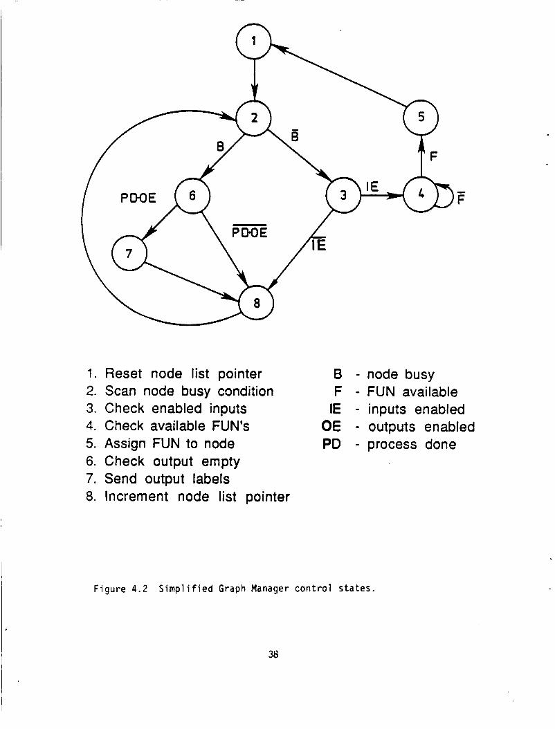
Figure 4.2 S i m p l i f i e d Graph Manager c o n t r o l s t a t e s .
38
1. Reset node list pointer B - node busy 2. Scan node busy condition F - FUN available 3. Check enabled inputs IE - inputs enabled 4. Check available FUN'S OE - outputs enabled 5. Assign FUN to node PO - process done 6. Check output empty 7. Send output labels 8. Increment node list pointer

i n order t h a t the GRM may t r a c k CMG token f low.
w i t h the GLM t o f a c i l i t a t e t h e appropr ia te access o f da ta conta iners.
GRM i d e n t i f i e s an i d l e FUN t o which i s passed l a b e l s i n d i c a t i n g p r i m i t i v e
execut ion and da ta conta iners o f i n p u t operands.
w i t h t h e GRM prov ides output da ta conta iners l a b e l s (when t h e y become
ava i l ab le ) and complet ion o f t h e processing events.
system of t h e FUN must manage graph a t t r i b u t e d e t a i l s w i th t h e GHM and
actual da ta management w i t h t h e GLM.
The FUN must communicate
The
Subsequent communication
Thus t h e opera t ing
A c o n t r o l f l o w didgram o f t h e pro to type FUN opera t ing system i s shown
i n F ig . 4.3.
" Z " .
Task ( Z = 3 ) , Wait f o r Empty Output Container, ( Z = 4 ) , and Output Data (Z=5) .
The c o n t r o l s t a t e o f t h e FUN opera t i ng system i s denoted b y
The f i v e c o n t r o l s ta tes are Wait ( Z = l ) , Fetch Data (Z=2) , Complete
4.6 Prototype G1 obal Memory
The GLM opera t ing system responds t o d i r e c t i v e s b y t h e FUN t o e i t h e r
f e t c h o r w r i t e operands t o t h e var ious da ta conta iner l a b e l s i n t h e g loba l
Inernory.
F igu re 4.4.
t o determine t h e request f o r t r a n s f e r o f data.
the type ( i n p u t o r output ) and l a b e l i s t r a n s f e r . Then t h e appropr ia te da ta
i s t rans fer red .
A s i m p l i f i e d opera t ing system f o r t h e pro to type GLM i s shown i n
The opera t ing system p o l l s each FUN s e r i a l communication p o r t
I f a t r a n s f e r i s requested,
4.7 Synthesis Considerat ions
The synthes is procedure f o r a p a r t i c u l a r r e a l i z a t i o n o f t h e ATAMM based
a r c h i t e c t u r e must preserve t h e graph model requirements. Care must be exer-
c ised no t t o change t h e behavior o f t h e ATAMM c h a r a c t e r i s t i c s as represented
by the NMG model. Thus coinmunication/data exchange events b u i l t i n t o t h e
a r c h i t e c t u r e must be modeled i n accordance wi th graph expansion r u l e s f o r
39

U I N
N II *
c, c 3 0 c, .C - 3 c a
V E 3
L L
(3
d
40

t
POLL FUN ( i )
F i g u r e 4 . 4 Global Memory Cont ro l Diagram.
41
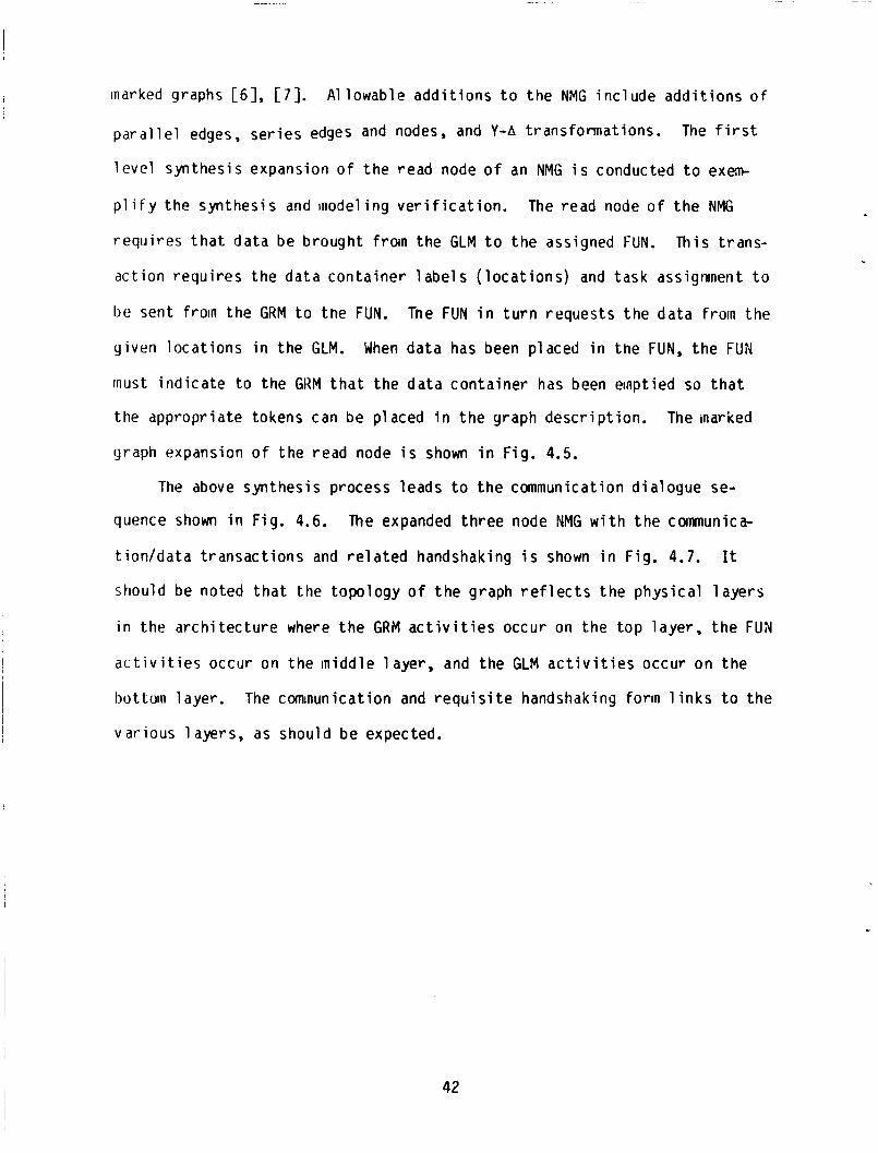
marked graphs [ 6 ] , [ 7 ] . A l lowable add i t i ons t o t h e NMG i nc lude add i t i ons o f
edges, se r ies edges and nodes, and Y-A t ransformat ions. The f i r s t
l e v e l synthes is expansion of t h e read node o f an NMG i s conducted t o exem
p l i f y the synthes is and modeling v e r i f i c a t i o n .
requ i res t h a t da ta be brought froin the GLM t o t h e assigned FUN. This t rans-
ac t ion requ i res the da ta conta iner l a b e l s ( l o c a t i o n s ) and task assignment t o
be sent froin the GRM t o the FUN. Tne FUN i n t u r n requests t h e da ta froin the
y iven loca t ions i n the GLM.
must i n d i c a t e t o the GKM t h a t t he da ta conta iner has been emptied so t h a t
the appropr ia te tokens can be placed i n t h e graph descr ip t ion .
graph expansion o f t he read node i s shown i n Fig. 4.5.
The read node o f t h e NMG
When data has been placed i n the FUN, t h e FUN
The marked
The above synthes is process leads t o t h e communication d ia logue se-
quence shown i n Fig. 4.6.
t i on /da ta t ransac t ions and r e l a t e d handshaking i s shown i n Fig. 4.7.
should be noted t h a t the topology o f t h e graph r e f l e c t s t h e phys ica l l a y e r s
i n t he a rch i tec tu re where the GRM a c t i v i t i e s occur on the t o p layer , t h e FUN
a c t i v i t i e s occur on the midd le layer , and the GLM a c t i v i t i e s occur on t h e
bottom layer .
var ious layers, as should be expected.
The expanded th ree node NMG w i t h t h e communica-
It
The cominunication and r e q u i s i t e handshaking forin l i n k s t o t h e
42

.
. ..
tn tn
/ E / o
L l e li I I I I I I I I I I I I I I I I 1 I \
\
I I I I I I I
I’
0, U 0 C
0 0 Q,
I
a I
I
- C 0,
E C 0, cn cn cn 0
x u) 0
0, > 0, V
.-
L
.-
I 1 0
0
0 U
3 a
e
e
L L .- e cn Q, 3 0 Q,
II a n
0 0 U
3
CI
.L,
a t ..
C 0
a Q, V 0, L
0 0 0 Q, 0, U Q,
E 0 C s V
II U
.. L
U
-
a
h
c Q, 3 0 G
43

f- C Q,
1 ' - c
x u
C 0
V C J lL
.- e
C I ;
U
.C
0 Y 0 L a
aJ L
Q, a .C
44

\
W e c
I I
I I I I I I \ \ \ \ \ \
z
\ \ \ \ \ \
- c
4
b \ i c a
l-0 L ;3
L Q x 0 J 0 I v
$ 0
X W
a
h
0
QI L 3 m . .-
I&
I 45

CHAPTER 5
5 .O EXPERIMENTAL EVALUATION
5.1 In t roduc t i on
Chapter f i v e presents a p r e l im inary eva lua t i on o f t h e pro to type imple-
mentat ion descr ibed i n Chapter Four.
development o f a d iagnos t ic procedure which i n t e r a c t s w i t h the GRM.
d iagnos t ics are discussed i n Sect ion 5.2.
t o i l l u s t r a t e bo th t h e behavior o f t he system and d iagnos t ic a t t r i b u t e s .
The eva lua t i on i s supported b y t h e
The
An a lgor i thm example i s executed
5.2 Systen Diagnost ics
The eva lua t ion o f t h e pro to type i s impor tant i n order t o determine i f
the system i s behaving i n accordance w i t h t h e ATAMM model. Analys is i s
d i f f i c u l t due t o the concurrent processing and communication events t a k i n g
place. An appropr ia te d iagnos t ic o r ana lys i s t o o l should make use o f t h e
p roper t i es o f the Graph Manager i n t h a t a l l system events a re known as a
t r a n s l a t i o n o f t h e CMG token placement and node f i r i n g s .
The Graph Manager has an i n t e r n a l r e a l t ime c lock which may be used t o
t ime mark each event. The events t o be recorded inc lude:
1.
2.
the assignment o f a FUN t o a p a r t i c u l a r node,
t h e a c q u i s i t i o n o f i n p u t da ta b y t h e node being processed,
3.
4.
5.
The format o f each o f t he e n t r i e s o f t h e r e p o r t con ta ins t h e nex t
the complet ion o f t he node processing,
the f u l l o r empty c o n d i t i o n o f t h e da ta conta iner labe ls ,
the w r i t i n g o f t he output data,
46

i tems o f in format ion:
I .
2.
3.
By record ing the event t ime o f every event o f a p a r t i c u l a r graph execu-
Time a t which the event took place.
Node a t which the event took place.
Type o f event (any o f the above).
t i o n , t he system can be analyzed. The ana lys is y i e l d s i n fo rma t ion on how
the var ious FUNs dispatch t h e i r respec t ive assignments, how they are con-
t r o l l e d by the da ta f l o w i n t h e system, and how they compete for memory
access.
da ta th ruput parameters.
in fo rmat ion t o a inore readable form i s be ing developed.
c a l led ANALYZER.
I n t e r m of performance, in fo rmat ion can be der ived t o evaluate
For such an analysis, a program t o t r a n s l a t e t h i s
This software i s
I n order t o demonstrate the general fea tures o f t h e ANALYZER program,
an example was r u n i n the pro to type system.
s t a t e equat ion a lgor i thm t h a t was p rev ious l y descr ibed
Recal l t h a t t h i s p a r t i c u l a r graph has eleven nodes, one
a lgor i thm and one output f rom t h e algor i thm. The a lgo r
w i t h a Fequence o f t en inputs .
Th is exainp e i s t h e p a r t i t i o n e d
n Sect ion 2.3.
i n p u t t o t h e
thm i s presented
Several f i g u r e s are presented t o i l l u s t r a t e t h e behavior o f t h e algo-
F igure 5.1 i s a d i s p l a y o f r i t h m and the d iagnos t ic products o f ANALYZER.
the a c t i v i t y o f the a lgor i thm graph nodes 1 t o 7.
axes ( t ime) w e a l igned i n order t o show the concurrent behavior of t h e
vdr ious notles. The lowest graph i s a d i s p l a y o f Node #l. The d i s p l a y i n d i -
cates when t h a t node becomes a c t i v e and the du ra t i on o f t h a t s ta te . For
t.his example, t h ree FUNs are a v a i l a b l e t o t h e system. Whenever a box i s
f i l l e d w i t h h o r i z o n t a l l i n e s i t i n d i c a t e s t h a t t h e Funct ional Uni t #1 i s
connected t o t h a t p a r t i c u l a r task o r node. V e r t i c a l l i n e s i n d i c a t e
I n these p lo t s , t he x-
47

NODE MTIUITY DISPIAY TIME &-TIHE 1 8
b i g d N's IlQuVoIltput
DEPW [ 1 I b b e r of ewents: W Execution tin: 18192
F i q u r e 5.1 Analyzer's Node Act iv i ty Display, Assigned F U ' s .
48

Funct ional IJn i t #2, 1 iries running from u p - l e f t t o down-r ight i n d i c a t e Func-
t . i or id l Uni t #3, and so on. The d i s p l a y can be changed i n o rder t o show the
,vwi int o f t irne requ i red t o execute the i n d i v i d u a l sub-processes ( i .e. da ta
input read time, process t i m e , wa i t i ny f o r da ta ou tpu t c l e a r and da ta ou tpu t
w r i t e time) f o r every node.
I io r i zon ta l 1 ines i n d i c a t e i n p u t read time, v e r t i c a l l i n e s i n d i c a t e process
time, l i n e s running f ro in u p - l e f t t o down-r ight i n d i c a t e w a i t i n g f o r da ta
outputs t o c lear , and l i n e s running from down- le f t t o u p - r i g h t i n d i c a t e da ta
output w r i t e time.
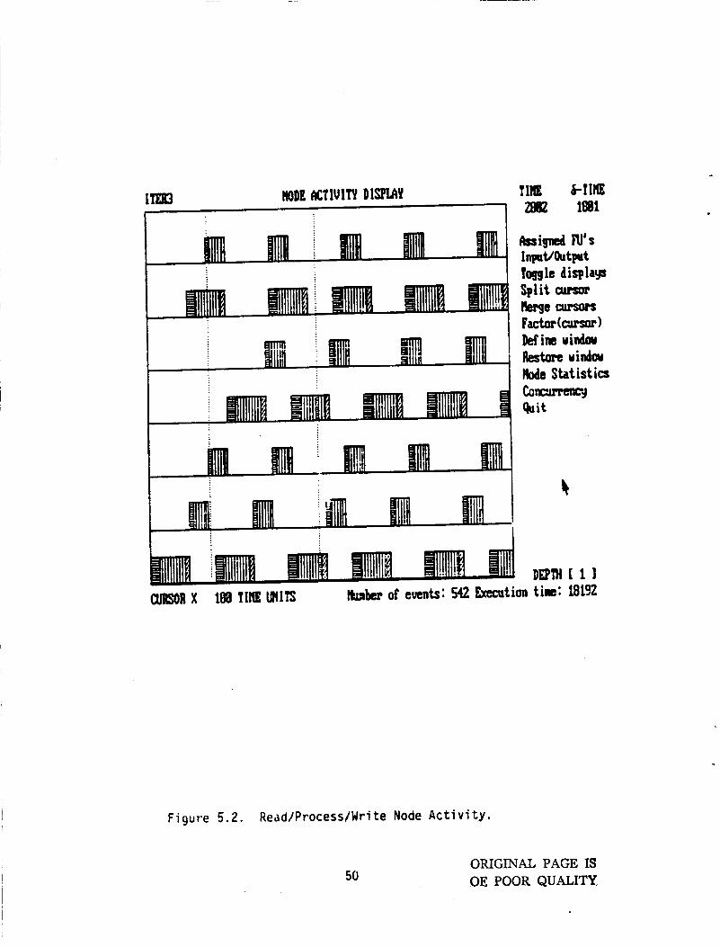
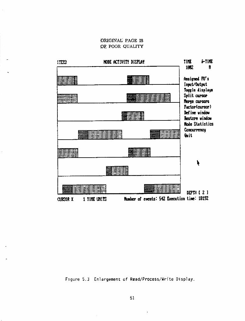
the data presented b y these d i sp lays i s t h e c a p a b i l i t y t o "zooin i n " t o a
marked sect ion. The r e g i o n enclosed b y t h e t w o cursors i n Fig. 5.2 i s en-
larged i n F ig . 5.3. Any o the r reg ion can be de f ined i n F ig . 5.3 and be
enlaryed again and so on.
processes marking are inore evident.
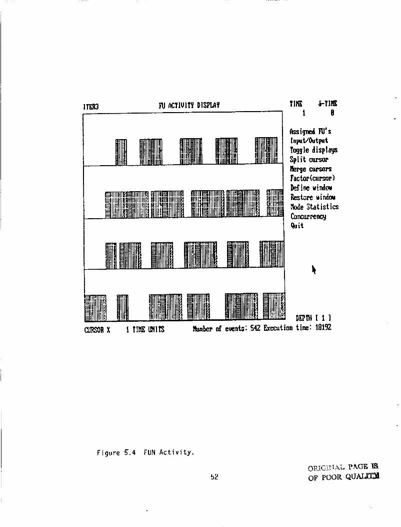
d c t i v i t y h i s t o r y o f each i n d i v i d u a l FUN.
f o r the a lgor i thm example i s shown i n Fig. 5.4. The bottom p l o t co r re -
sponds t o Funct ional U n i t #l. It i s a l so poss ib le t o app ly t h e "zoorn'l fea-
t u r e t o t h i s screen.
shown i n F i g . 5.2.
This p resenta t ion format i s shown i n F ig . 5.2.
A f e a t u r e t h a t helps t h e user t o more c l o s e l y exanine
In t h i s case t h e d i f f e r e n c e s between t h e sub-
An add i t i ona l d i s p l a y prov ides a t ime
Th is ANALYZER FUN a c t i v i t y d i s p l a y
The i n t e r p r e t a t i o n o f t h e pa t te rns i s t h e sane as
Of p a r t i c u l a r importance i s t h e quan t i f y i ng o f t n e a l g o r i t h n da ta
pcrfonnance. The ANALYSER program prov ides d i sp lays t o i n d i c a t e The Input
t o Output t i m e (TBIO), Time between Inputs (TBI) , and Time between Outputs
( T U O ) . For the a lgor i thm example having a sequence o f t en inputs, Fig. 5.5
Tne s o l i d l i n e r e p r e shows t h e tabulated va lues and a p i c t o r i a l d i sp lay .
sents T B I , t h e dashed l i n e represents TBIO, and t h e do t ted l i n e represents
THO. The graphs a r e n o t presented on t h e same scale, b u t a r e presented t o
prov ide qual i t a t i v e in format ion on t h e t r a n s i e n t and steady s t a t e
49
kignd N's InpuVOutput
I I Toggle displays
I Mine uiwiou Restore uindm M e Statistics
F i g u r e 5.2. Redd/Process/Wri t e Node A c t i v i t y .
50 ORIGINAL PAGE IS OE POOR QUALITY
ORIGINAL PAGE IS SI€! POOR QUALITY
Clssigned N's InpuVhtput
I I Toggle displays
Define uindw Restart uindw M e Statistics
CURIORX 1YItlEMlTS h b e r d emts: 542 Execution t ie: 18192
Figure 5.3 Enlargement o f ReadlProcessiWrite Display.
51
Toggle displays Split cursor krge cursors
W R X 1 TIHEMITS b b e r of events: 542 Execution ti=: 18192
Figure 5.4 FUN A c t i v i t y .

ITER3 IHPUI/OUTPUT DISPIA'I
lei; le677",Mv
12: P la67 la67 2213 11: -#
OEPM t 1 1 ClJBORX 1 T M E ~ I l ' S haher d eueuts: 542 Execution tine: 18192
TIHE H I H E 1 8
Figure 5.5 Timing Analysis Display.
53

c h a r a c t e r i s t i c s o f these performance measures. An add i t i ona l performance
s t a t i s t i c provided by ANALYZER i s t h e mean va lue of every sub-process t ime
f o r a q iven node f o r the e n t i r e process.
currier o f Figs. 5.1, 5.2, 5.3 and 5.4 con ta in t h i s in for .nat ion f o r several
nodes.
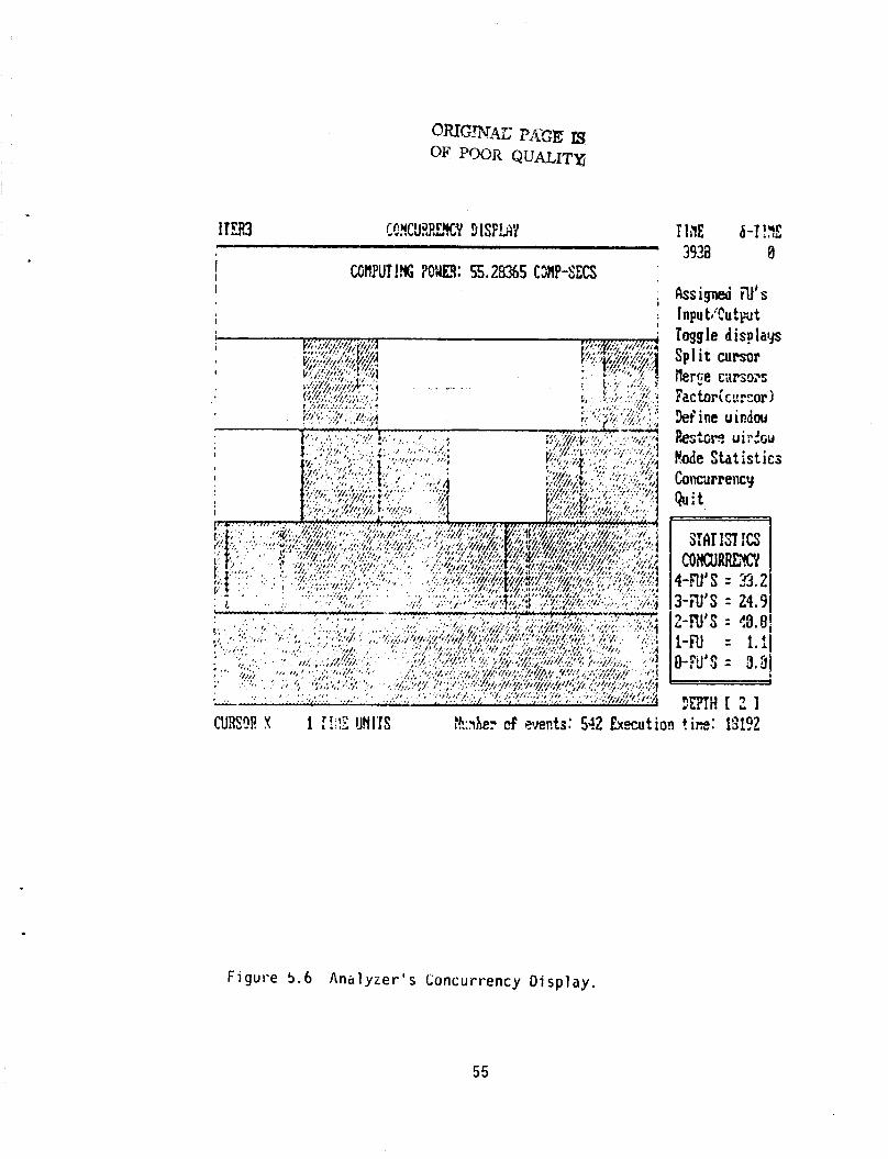
F i g . 5.6.
same t ime versus time. The box i n the lower r i g h t corner i nd i ca tes t h e
percentage o f the t o t a l t ime i n t h e v iewpor t t h a t a g iven nunber o f nodes o r
FUNS are working a t t h e same time. Time between any two p o i n t s along t h e x-
ax is can be measured us ing a double cursor arrangement. One cursor i s f i x e d
and the o ther can be placed a t any p o i n t i n time.
bo th i s con t inuous ly repor ted i n the upper r i g h t corner o f t he screen as
shown i n Fig. 5.2.
The boxes i n the lower r i y h t
The "concurrency' o f a se lec ted reg ion i n t ime i s i l l u s t r a t e d i n
This p l o t t i n g snows t h e nunber o f nodes t h a t are working a t t h e
The d i f f e r e n c e between
The SIMULATION prograrn, as repor ted i n [ 8 ] , has been mod i f i ed i n order
t o r e p o r t t he same t ype o f in fo rmat ion as t h e hardware system.
Fashion, t h e execut ion o f a s p e c i f i c graph can be compared t o t h a t o f t h e
simulated behavior using t h i s analyzer program.
prograrn can be ' tuned ' t o the hardware f o r more accuracy.
proyran w i l l r un i n an I B M PC o r t r u e compat ib le w i t h a t l e a s t 256k o f
inanory, one d i s k d r i v e and an Enhanced Graphics Adapter w i th a t l e a s t 64k o f
iiianory and e i t h e r an Enhanced Color Disp lay o r Monochrome Display.
vers ion used f o r the f i g u r e s w i l l r un under these d i s p l a y r e s t r i c t i o n s us ing
an Enhanced Color D isp lay (640x350 p i x e l s ) o r Monochroane D isp lay us iny j u s t
four c o l o r s o r tones.
using a Color Disp lay and showing up t o s i x teen c o l o r s (b40X200 p i x e l s ) o r
w i t h an Enhanced Color D isp lay a l so w i t h s i x teen c o l o r s (640x350 p i x e l s ) .
I n t h i s
This way t h e s imu la t i on
The ANALYZEK
The
There i s another ve rs ion o f t he proyran t h a t w i l l r un
54
IIRE h-T!!?E 3938 0
Assigned U s Inpu tiCu tpt Toggle displays Split cursor iler2e C;IFS;OZS
FEC tori c ccor 1 Wine uidw Pastm u i:*Gw fade Statistics Concurrency Quit
Figure 5 . 6 A n a l y z e r ' s Concurrency D isp lay .
55

Th
tl ev e 1 o p
grained
CHAPTER 6
6.0 COUCLUSIONS AND FUTURE DIRECTIONS
s r e p o r t has presented t h e r e s u l t s o f ongoing research d i r e c t e d a t
ny a graph t h e o r e t i c model f o r desc r ib ing t h e behavior o f l a r g e
a lgor i thms i n a spec ia l d i s t r i b u t e d computer environment. The ATAMM
model has been shown t o p rov ide a b a s i s f o r e s t a b l i s h i n g da ta f l o w arch i tec-
t u r e design r u l e s as wel l as p rov id ing a t h e o r e t i c a l bas is f o r determin ing
performance c h a r a c t e r i s t i c s o f a lgor i thms whose da ta f l o w i s descr ibed b y
d i r e c t e d graphs.
The t h e o r e t i c a l m e r i t o f t h e ATAMM Model i s der ived from a spec ia l
c lass o f P e t r i Net graphs c a l l e d marked graphs.
t h e c i r c u i t p roper t i es o f t h e ATAMM computat ional marked graphs which de-
sc r i be bo th da ta f l o w and c o n t r o l f l o w w i t h i n t h e a lgor i thm and da ta f l o w
d r c h i tec tu re .
approach t o determine a n a l y t i c a l bounds on c e r t a i n aspects o f t h e computa-
t i o n a l performance. These p roper t i es i nc lude which i s t h e minimum
O f p a r t i c u l a r i n t e r e s t i s
Froin these p roper t i es , t h i s research has developed an
where T i s t h e lower
Another comput a t i ona 1 min
admi ssabl e oper a t i n g
eted w i t h i n t h i s time.
The research represents a s i g n i f i c a n t beginning i n t h e development o f
an a n a l y t i c a l methodology f o r determin ing computational performance measures
f o r concu r ren t l y processed a lgor i thms.
c lude such d i r e c t i o n s as
Future work i s a n t i c i p a t e d t o i n -
1. Performance o p t i m i z a t i o n
. 2. Operator decomposition f o r maximal use o f resources
3. Fau l t to le rance s tud ies based on t r i p l e mode redundancy
56
number o f f unc t i ona l u n i t s requ i red t o achieve T m i n bound on the t ime requ i red t o complete an opera t ion
bound, Tmax i s defined t o be an upper bound f o r a l l
cond i t ions . It i s noted t h a t a task i s always comp

4. Uevelopnent o f an experimental testbed using micro-computers and
LAN coininuri i c a t i or1 5 . Oevelopnent o f a more d e t a i l e d node marked graph character izat ion
f o r inore precise ly account for read and w r i t e tiininy.
Develop a l g o r i thn graph augmentation techniques t o adjust perfor-
mance i n the presence o f 1 irnited computing resources.
5.
6 .
57

REFERENCES
1.
2 .
3.
4.
5 .
6.
7.
9.
C. P e t r i , "Kommunikation l n i t Automaton," Ph.D Disser ta t ion, U n i v e r s i t y of Bonn, West Germany, 1962.
A. H o l t and F. Camoner, "Event and Condit ions" Appl ied Data Research, New York, 1970.
J. L. Peterson, P e t r i Net Theory and the Modeling o f Systems, Englewood C1 i f f s , N. J. , Pren t i ce -Ha l l , 1981.
T. Murata, " C i r c u i t Theoret ic Analys is and Synthesis o f Marked (4-aphs ,I' I E E E Transact ions on C i r c u i t s and Systems, Vol. CAS-24, No. 7, pp. 400- 405, J u l y 1977.
J. W. Stoughton and R. R. Mielke, " P e t r i Net Model f o r Concurrent Pro- cessing of Complex A1 yorithms," Proceedings 1986 Government Micro- c i r c u i t App l i ca t i ons Conference, Vol. 12, pp. 11-14, November 1986.
T. Murata and J. Koh, "Reduction and Expansion o f L i v e and Safe Marked Graphs," IEEE Transact ions on C i r c u i t s and Systems, Vol. CAS-27, No. 1, January 1980.
H. Johnsonbauyh and T. Murata, "Add i t i ona l Methods f o r Reduction and Expansion of Marked Graphs," IEEE Transact ions on C i r c u i t s and System, Vol. CAS-28, No. 10, October 1981.
K. Jackson, H. Tynchyshyn, R. Mielke, J. Stoughton and K . Obando, "Sirn- u l a t i o n Software f o r Concurrent Processing," Proceedings o f Southeastcon 87, Tampa, FL A p r i l 1987.
S. Seshu, and M. Reed, L inea r Graphs and E l e c t r i c a l Networks, Addison- Wesley Pub l i sh ing Co., Inc., 1961.
58

IT TI< I -NE TS
. F. Cannoner, "Deadlocks i n P e t r i Nets ,'I Report CA-7206-2311, 'ulakefield,
Massachusetts, Computer Associates, (June 1972), 50 pages.
f-. Cocmnoner, A. Hol t , S . Even, and A. Pnueli, "Marked D i rec ted Graphs," Journal o f Computer and System Sciences, Volune 5, Number 5, (October 1971), pages 511-523.
11. UeVi l l e rs , and G. Louchard, "Rea l i za t i on o f P e t r i Nets Without Condi- t i o n a l Statements," I n fo rma t ion Processing L e t t e r s , Volune 2, Number 4, (October 1973), payes 105-107.
H. Genrich and E. Stankiewicz-Wiechno, "A D i c t i o n a r y o f Some l3asic Not ions o f N e t Theory," Lecture Notes i n Computer Science, B e r l i n : Springer- Verl ag, (1980).
[Genrich and Lautenbach 19781 H. Genrich, and K. Lautenbach, "Facts i n P1 ace/Transi tion-Nets," Proceedings o f t h e Seventh Synposiun on Mathe- ma t i ca l Foundations o f Computer Science 1978, Lecture Notes i n Computer Science, Volune 64, B e r l i n : Springer-Verlag, (September 1978), pages 213- 9 9 1 C31.
A . Hol t , and F. Cmnoner, "Events and Conditions," Record o f t h e P r o j e c t MAC Conference on Concurrent Systems and Para1 l e 1 Computation, New York: ACM, (June 1970), pages 1-52.
M. Jaritzen and I?. Valk, "Formal P roper t i es o f Place T r a n s i t i o n Nets," Lec- t u r e Notes i n Computer Science, B e r l i n : Springer-Verlag. (1980).
L. Kinney , and Y. Han, "Reduction o f P e t r i Nets," Proceedings o f t h e 1 4 t h A1 l e r t o n Conference on C i r c u i t s and Systens Theory, ( Septelnber 1976).
T. Murata, "State Equations, C o n t r o l l a b i l i t y and Maximal Matchings o f P e t r i Nets," IEEE Transact ions on Automatic Control, Volune AC-22, Number 3, (June 1977), payes 412-416.
Proceedings o f t h e Tenth Annual Asilomar Conference on C i r c u i t s , Systems, m d Computers, (November 1976), pages 202-206.
C i r c u i t s and Systems Soc ie ty Newslet ter , Volune 11, Number 3, (June 1Y77), payes 2-12.
T. Murata, " A Method f o r Synthesiz ing Marked Graphs f rom Given Markings,"
T . Murata, " P e t r i Nets, Marked Graphs, and C i r c u i t-System Theory," I E E E
T. Murata, " C i r c u i t Theoret ic Analys is and Synthesis o f Marked Graphs," I E E E Transact ions on C i r c u i t s and Systems, Volune CAS-24, Number 7, ( J u l y 1977), pages 400-405.
T. Murata, and R. Church, "Analys is o f Marked Graphs and P e t r i Nets b y M a t r i x Equations," Research Report MDC 1.1.8, Department o f I n f o r m a t i o n Engineering, U n i v e r s i t y o f I l l i n o i s , Chicago, I l l i n o i s , (November 1975).
59
T. Murata, and T. Shah, "On Liveness, Deadlock, and Reachab i l i t y o f E-Nets," Proccedinys o f t he 14 th Annual A l l e r t o n Conference on C i r c u i t s and Sys tem Theory, (September 1976), pages 597-605.
T. Murata, R. Church, and A. Pmin, "Mat r ix Equations f o r P e t r i Nets and Marked Graphs," Proceedings o f t he N i n t h Annual As i lanar Conference on C i r c u i t s , System, and Computers, (November 1975), pages 36-41.
C. P e t r i , " I n t r o d u c t i o n t o General Net Theory," Lecture Notes i n Computer Science, B e r l i n : Spr inger-Ver lag, (1980).
, J . Si fak is , "S t ruc tu ra l Proper t ies o f P e t r i Nets," Proceedings o f t h e Seventh Symposiun on Mathematical Foundations o f Computer Sc ience 1978, Lecture Notes i n Computer Science, Vol m e 64, Ber l i n : Spr inger-Ver l ag, (September 1978), pages 474-483.
S. Yu, and T. Murata, "PT-marked Graphs: A Reduced Model o f P e t r i Nets," Proceedings o f t h e 16 th A1 l e r t o n Conference on Communication, Cont ro l and Computing, (October 1978).
H. J. Genrich, K. Lautenbach, and P. S. Thiagarajan, "Elements o f General Net Theory," Net Theory and Appl i ca t i ons , Lec ture iJ0 t e s i n Computer Science, vo l . 84, Springer-Ver lag, New York, 1980. pp. 21-164.
E. W. May, ''An Alyor i th in f o r t h e General P e t r i Net Reachab i l i t y Problem, Procs, o f t h e 13 th Annual ACM Symposiun on Theory o f Computing, May 1981, pp. 238-246.
J. L. Peterson, P e t r i Net Theory and t h e IYodeling o f Systems, Prent ice-Ha l l , Enylewood C I i f f s , N. J., 1981.
A. T. Pmin and T. Murata, " A Charac te r i za t i on o f L i ve and Safe Markings o f D i rec ted Graphs," Proceedings o f t h e 1976 Conference on I n f o . S c i . and Syst ., Johns Hopkins Un ive rs i t y , Bal t imore, March 1976.
T. Murata and J. Y. Koh, "Reduction and Expansion o f L i ve and Safe Marked Graphs," I E E E Transact ions on C i r c u i t s and Systems, v o l . CA -27, No. 1, Jan. 1980. pp. 68-70.
R . Johnsonhaugh and T. Murata, "Add i t i ona l Methods f o r Reduction and Expansion o f Marked Graphs," I E E E Transact ions on C i r c u i t s and Systems; idem. "Analys is o f Resource Requirements i n Marked Graph Computation Models," Proceedings o f t h e 1980 I n t e r n a t i o n a l Symposiun on C i r c u i t s and Systems, Apr. 1980, pp. 342-345.
E. Pless and H. Plunnecke, " A B ib l i og raphy o f Net Theory," Report ISF, ISF- 79-04, GMD, Bonn, August 1979.
MOIIELS FOR CONCURRENT PROCESSING
I). Adarns, " A Model f o r Paral l e 1 Computations ,'I Paral l e 1 Processor Systems, Technologies and App l ica t ions , New York: Spartan Books, (1970), pages 311 -334.
60

.
T . Ayerwala, "Some App l i ca t i ons o f P e t r i Nets," Proceedings o f t h e 1978 Nat ional E lec t ron i cs Conference, Vol une 23, (October 197R), pages 149-1 54.
1'. Arena, R . Va let te , a i d M. D iaz , " P e t r i Nets as a Cmnon Tool for Design V c r i f i c d t ion and Ilardwart. Simul ation," Proceedings 1 3 t h Design Automation Conference, New York: I E E E , (June 1976), pages 109-116.
J. fJaer, "A Survey o f Sane Theoret ica l Aspects o f Mu1 t iprocess ing," Cornputing Surveys, Volune 5, Number 1, (March 1973), pages 31-80.
J . Cotronis, and P. Lauer, " V e r i f i c a t i o n o f Concurrent Systerfls of Processes," Proceedings o f t h e I n t e r n a t i o n a l Computing Synposiun 1977, Amsterdam North-Holland, ( A p r i 1 1977), pages 197-207.
S . Foo, and I;. Musgrave, "Comparison o f Graph Models f o r P a r a l l e l Computation and Thei r Extension," proceedings o f t h e 1975 I n t e r n a t i o n a l Synposi un on Computer Hardware Desc r ip t i on Languages and Thei r Appl i c a t i o n s , New York: IEEE, (September 1975), pages 16-21.
R. L ipton, L. Snyder, and Y. Za lcste in , "A Comparative Study o f Models of P a r a l l e l Computation," Proceedings o f t h e 1 5 t h Annual Symposiun on Switching and Automata Theory, N e w York: IEEE, (October 1974), pages 145-1 55.
R. M i l l e r , "A Comparison o f Some Theoret ica l Models o f P a r a l l e l Coinputation," IEEE Transact ions on Computers, Volune C-22, Number 8, (August 1973) , pages 710-71 7.
J. Peterson, and T. Bredt, "A Comparison o f Models o f P a r a l l e l Computation," In format ion Processing 74, Proceedings o f t h e 1974 I F I P Congress, h s t e r d a n : North-Hol l and, (August 1974), pages 466-470.
F. h n m i y , "Petr i -Net Based Descr ip t ion, Analys is and Si inulat ion o f Concurrent Processes," Proceedings 14 th Oesign Automation Conference, New York: IEEE, (June 1977).
K. Lautenbach m d H. A.Schmid, "Use o f P e t r i ne ts f o r p rov iny co r rec tness o f concurrent systelns," Proceedings o f I F I P Congress 74, North Hol land Pub. CO., 1974, pp. 187-191.
H. t. M i l l e r , "Sane r e l a t i o n s h i p s between va r ious models o f p a r a l l e l i s m and synchronizat ion," Report RC-5074, IBM T. J. Watson Res. Center, Yorktown Heiyhts, N. Y., Oc t . 1974.
T . Plurata, "Relevance o f Network Theory t o Models o f D i s t r i b u t e d / P a r a l l e l Processing," Journal o f t h e F r a n k l i n I n s t i t u t e , vo l . 310, no. 1, 1980, pp. 41-50.
C. Rarnchandam, "Analys is o f Asynchronous Concurrent Systems b y Timed P e t r i Nets," Report TH-120, P r o j e c t MAC, MIT, Cambridge, Mass., Feb. 1974.
61
I . Cox, Jr., " P r e d i c t i n g Concurrent Computer System Performance Using P e t r i Net Models ,I' Proccetlinys o f t he 1978 ACPl,(Decanber 1!J7 t j ) , payes 901-913.
Y. Itan, "Perforiiidnce Eva lua t ion o f a D i g i t a l System Usiny a P e t r i N e t - l i k e Approach," Proceedings o f the Nat iona l E l e c t r o n i c s Conference, Volune 23, (October 19/8U, pages 166-112.
W. Heiinerdinyer, "A P e t r i Net Approacn t o System Level Fau l t Tolerance Analysis, Proceedings o f t h e Nat iona l E l e c t r o n i c s Conference, Volune 23, (October 1978), pages 161-165.
Modeling and Eva lua t i on o f Computer Systems: Proceedings o f t h e T h i r d I n t e r n a t i o n a l Workshop on Model i n g and Performance Eva lua t ion of Computer System, Ansterdan: Nor th Holland, (1977), pages 75-93.
3. S i f a k i s , "Use o f P e t r i Nets f o r Performance Evaluation, Measuring,
-.
J. Si fak is , "Rea l i za t i on of Fau l t -To le ran t Systems b y Coding P e t r i Nets," Proceedings o f t h e E igh th Annual I n t e r n a t i o n a l Conference on Fau l t - Tolerant Computing, New York: IEEE, (June 1978), page 205; Also ( r e v i s e d ) Journal o f Design Automation and Faul t -To le ran t Computing, Volune 3, Nunber 2, (1979).
J. Si fak is , "Use o f P e t r i Nets f o r Performance Evaluation," Advanced Course on General Net Theory o f Processes and Systems, Hamburg, (October 1979); Also Lecture Notes i n Computer Science, B e r l i n : Springer-Verlag. (1980).
G . S. Ho and C. V. Rananoorthy, "Performance Eva lua t ion o f Asynchronous Concurrent Systems Using P e t r i Nets," IEEE Transact ions on Software Enyineering, v o l . SE-6, no. 5, Sept. 1980, pp. 440-449.
T. Murata, "Synthesis o f Deci sion-Free Concurrent Systems f o r Prescr ibed itesources and Performance," I E E E Transact ions on Software Engineeriny, v o l . SE-6, no. 6, Nov. 1980, pp. 525-530.
DATA FLOW ARCH I TECTUKE
J. Dennis, "Modul ar, Asynchronous Contro l S t ruc tures f o r a High Performance Processor," Record o f t h e P r o j e c t MAC Conference on Concurrent Systems and P a r a l l e l Computation, New York; ACM, (June 1970), payes 55-80.
C. Sei t z , "Asynchronous Machines E x h i b i t i n g Concurrency," Record o f t h e P r o j e c t MAC Conference on Concurrent Systems and Para1 l e 1 Computation, New York: ACM, (June 1970), pages 93-106.
M. Sowa and T. Murata, " A d a t a f l ow computer a r c h i t e c t u r e w i t h program and token memories," Procs. o f t h e 14th Asilomar Conf. o n C i r c u i t s , Systems, and Computer, I E E E Comp. Society, Long Beach, Cal., Nov. 1980. Also I E E E Trans. on Computers, Sopt. 1982, pp. 820-824.
S. li. Yu and T. Murata, "Modeling and s imu la t i ng d a t a f l o w computations a t machine 1 anyuage 1 evel," Procs. o f Conf. on Simulat ion, Measurement and Modeling o f Computer Systems, ACM, New York, Aug. 1979, pp. 207-213.
.
62

,I. 13. Dennis "Data F l o w Supercomputers," Computer, v o l . 13, Nov. 1980, pi). 48-56.
5 . 5 . I k d d i , "A Para l le l Computer with C e n t r a l i z e d Con t ro l , " I E E E Comp. So. I<flposi tory, V16-72, Feb. 1976.
63
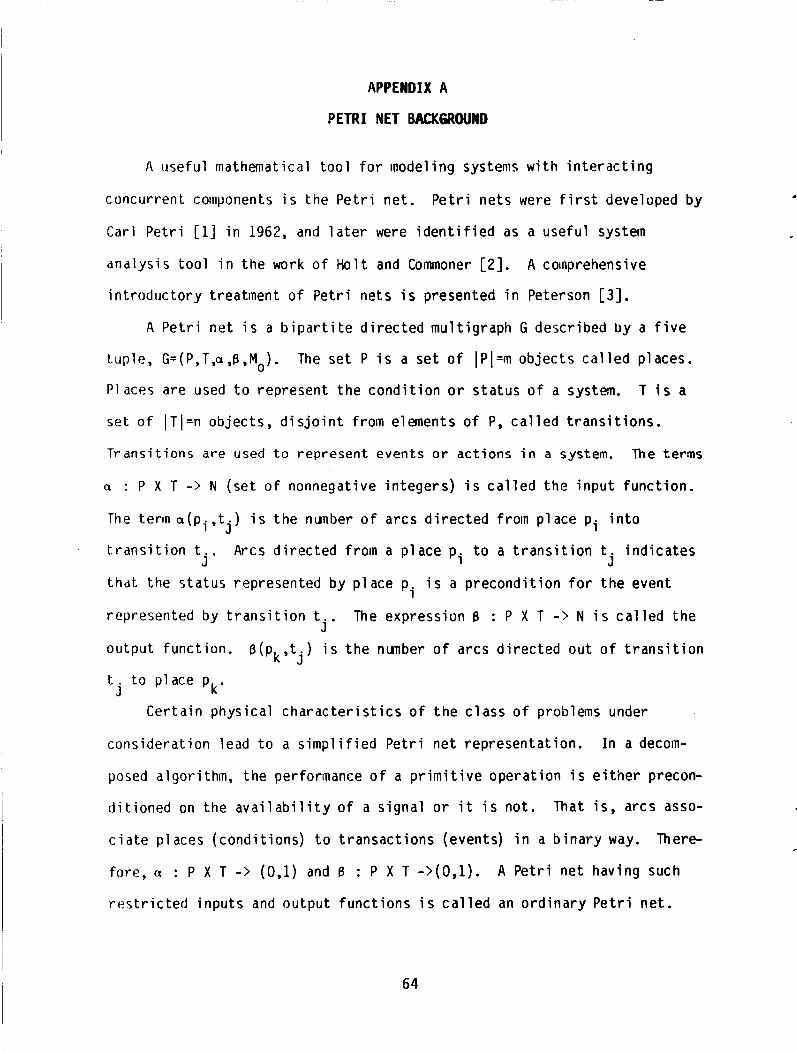
APPENDIX A
PETRI NET BACKMOUND
I\ usefu l mathematical t o o l f o r modeling systems w i t h i n t e r a c t i n g
concurrent components i s the P e t r i n e t .
C a r l P e t r i [l] i n 1962, and l a t e r were i d e n t i f i e d as a use fu l system
ana lys i s t o o l i n the work o f H o l t and Commoner [ Z ] . A comprehensive
i n t roduc to ry t reatment o f P e t r i ne ts i s presented i n Peterson [3].
P e t r i ne ts were f i r s t developed by
A P e t r i n e t i s a b i p a r t i t e d i r e c t e d mu l t i g raph G descr ibed by a f i v e
The se t P i s a s e t o f IPI=rn ob jec ts c a l l e d places.
T i s a
t up le , G=(P,T,a,B,Mo).
P1 aces are used t o represent t h e c o n d i t i o n o r s ta tus o f a system.
se t o f IT I=n ob jec ts , d i s j o i n t f rom elements o f P, c a l l e d t r a n s i t i o n s .
Transitions are u s e d t o represent events or actions i n a system. The terms
o : P X T -> N ( se t o f nonnegative i n tege rs ) i s c a l l e d t h e i n p u t f unc t i on .
The term a(pi , t . ) i s t h e nunber o f a rcs d i r e c t e d frorn p lace pi i n t o
t r a n s i t i o n t
t h d t the s ta tus represented by p lace p i represented by t r a n s i t i o n t The expression B : P X T - > N i s c a l l e d t h e
output funct ion. ~ ( p , t . ) i s t h e nunber o f arcs d i r e c t e d ou t o f t r a n s i t i o n
t . t o p lace p
J Arcs d i r e c t e d f rom a p lace pi t o a t r a n s i t i o n t i n d i c a t e s
j' j i s a p recond i t i on f o r t h e event
j '
k J
k ' J Cer ta in phys ica l c h a r a c t e r i s t i c s o f t h e c l a s s o f problems under
cons idera t ion lead t o a s i m p l i f i e d P e t r i n e t representa t ion .
posed algor i thm, the performance of a p r i m i t i v e opera t ion i s e i t h e r precon-
d i t i o n e d on the a v a i l a b i l i t y o f a s igna l o r i t i s no t . That i s , arcs asso-
c i a t e places (cond i t ions) t o t ransac t i ons (events) i n a b i n a r y way. There-
fore, J : P X T -> ( 0 , l ) and B : P X T - > ( O , l ) .
r e s t r c ted i npu ts and output f u n c t i o n s i s c a l l e d an o r d i n a r y P e t r i ne t .
I n a decom-
A P e t r i ne t having such
64

Arcs d i r e c t e d from a t r a n s i t i o n t . t o a p lace p J k i n d i c a t e s t h a t the
ac t i on represented b y t r a n s i t i o n t t o a p lace p r e s u l t s i n t h e s t a t u s
represented b y p lace pk.
the corresponding p lace w i t h one o r more tokens. M0:P - > N i s c a l l e d the
i n i t i a l marking vector .
marking each place.
j k A c o n d i t i o n may e x i s t and i s i nd i ca ted b y marking
The components o f Mo i d e n t i f y t h e nunber o f tokens
The placement o f tokens i n a P e t r i net , and the s t a t u s o f t h e co r re -
sponding system, evolve according t o t h e f o i l o w i n g r u l e s .
i s enabled i f a l l i npu t places con ta in a t l e a s t as many tokens as i n p u t
drcs.
f i r e s , tokens i n each i n p u t p lace p . equal i n nunber t o the nunber o f i n p u t J
arcs a ( p . , t . ) are removed.
t o the nunber o f ou tpu t arcs B(pk,ti) are deposited.
cont inue as long as a t l e a s t one t r a n s i t i o n i s enabled.
enabled t r a n s i t i o n s , t h e execut ion o f t h e n e t h a l t s .
A t r a n s i t i o n ti
k a t i s , M(p) > a(p,ti) f o r a l l p E: P. When an enabled t r a n s i t i o n ti
Tokens i n each ou tpu t p lace pk equal i n nunber J 1
T r a n s i t i o n f i r i n g s
When t h e r e a re no
The concept o f t ime i s n o t e x p l i c i t l y inc luded i n t h e d e f i n i t i o n of
P e t r i nets.
i s necessary and usefu l t o d e f i n e t imed delays associated w i t h t h e perfor-
mances o f events. Such a P e t r i n e t i s c a l l e d a t imed P e t r i n e t and i s
de f ined by the s i x - t u p l e G = (P,T,a,B, Mo,X) .
a s prev ious l y def ined.
i 5 c a l l e d the f i r i n g t ime func t i on .
de lay associated w i t h each t r a n s i t i o n .
tiowever, f o r performance eva lua t ion and schedul i n y problems, i t
The f i r s t f i v e paraneters a re
The f u n c t i o n X : T -> R (nonnegat ive r e a l nunbers)
The components o f X i d e n t i f y t h e time
The placement o f tokens i n a t imed
Tokens have two s ta tes
i n p u t I
As
P e t r i ne t evolve according t o the f o l l o w i n g ru les .
c a l l e d reserved and non-reserved. A t r a n s i t i o n ti
places conta in a t l e a s t as many non-reserved tokens
before, an enabled t r a n s i t i o n may o r may n o t f i r e .
s enabled i f a1
as i n p u t arcs.
When an enaDled
65

t r a n s i t i o n t . f i r e s , t h e f i r i n g process commences b y changing t h e s ta tus o f
tokerir i n each i n p u t p lace p
a(P ,t ) , froin non-reserved t o reserved. j i
X ( t . ) t ime u n i t s a f t e r i n i t i a t i o n b y removing a(p . , t \ reserved tokens froin 1 J
each i npu t p lace p
output p lace p
1
equal i n nunber t o tne nunber o f i n p u t a rcs j’
F i r i n g o f t r a n s i t i o n ti terminates
and depos i t ing B(Pk,ti) non-reserved tokens a t each j’
k ’ Two ve ry impor tant subclasses o f P e t r i n e t s a r e s t a t e machines and
marked graphs.
r e s t r i c t e d t o having e x a c t l y one i n p u t p lace and one output place.
graph i s t h e dual o f a s t a t e machine.
which each p lace i s r e s t r i c t e d t o having e x a c t l y one i n p u t t r a n s i t i o n and
one output t r a n s i t i o n .
p lace w i t h several output t r a n s i t i o n s , b u t cannot model t n e c r e a t i o n and
des t ruc t i on o f tokens requ i red t o model concurrency o r t h e w a i t i n g which
charac ter izes synchronizat ion.
model c o n f l i c t s o r data-dependent dec is ions, b u t can model concurrency.
A s t a t e machine i s a P e t r i n e t i n which each t r a n s i t i o n i s
A marked
A marked graph i s a P e t r i n e t i n
Thus, a s t a t e machine can represent c o n f l i c t s b y a
Marked graphs, on t h e o the r hand, can n o t
.
66

APPENDIX B
PUBLICATIONS AWD PRESENTATIONS
1. John W. Stoughton and Roland R. Mielke, " P e t r i Net Model f o r Concurrent Processing o f Complex A1 orithms," Government M i c r o c i r c u i t App l i ca t i ons Conference, Vol. 12 pp. 9 1-14, Nov. 1986.
2. K. Jackson, R. Tynchyshyn, John W. Stoughton and Roland R. Mielke, "S imulat ion Software f o r Concurrent Processsing," Proceedings o f Southeastcon 1987. Tampa, FL. Apr. 1987.
67
1 . Report No. 2. Government Accession No.
i IA '>A CN- 181657 4 rille and Subtitle
SIHATEGJES FUR CONCURRENT PROCESSING OF (;OMPLEX / \ I -GOKI lHMS I N DATA D R I V E N ARCHITECTURES
3. Recipient's Catalog No.
5. Repon Date FEBRUARY 1988
6. Performing Organization Code
7. Key Words (Suggested by Authorlsl)
concur ren t processing, marked graphs, Pe t r i -ne t , da ta f l o w a rch i tec tu re , d i s t r i b u t e d computing, l a rge gra ined a lgor i thms
I
7 Author(r) 8. Performing Organization Report No.
18. Distribution Statement
Unclass i f ied-Unl i m i t ed Subject Category 33
,Jotin W . 5 i.oughtcrn Roland H. Mielke
9 Security Clauif (of this report) 20. Security Clauif. (of this paprl 2t. No. of Peger
U n c l a s \ i f i e d Unc lass i f i ed 7 1
9. Performing Organization Name and Address Old Dominion U n i v e r s i t y Research Foundation P.O. Box 6369 Nor fo lk , V i r g i n i a 23508
22. Rice'
A04
2. Swnroring Agency Name and Address
Nat ional Aeronaut ics and Space Admin i s t ra t i on Lanqley Research Center
10. Work Unit No.
584-02-11-01
NAG1-683 13. Type of Report and Period Covered
I Contractor Report I 14. Sponsoring Agency cock
" - Hanipton, VA 23665 I I cxhn ica l Moni tor : Paul J . Hayes P t i r i c i pa l I n v e s t i g a t o r : D r . John W. Stoughton
5 Supplementary Notes
6. Abstract
Research d i r e c t e d a t developing a graph t h e o r e t i c model f o r desc r ib ing data and c o n t r o l f l o w associated w i t h the execut ion of l a r g e gra ined a lgor i thms i n a spec ia l d i s t r i b u t e d computer environment i s presented. Th is model i s i d e n t i f i e d by the acronym ATAMM which represents A lgo r i t hm 10 A r c h i t e c t u r e Mapping Model. o f such a model i s t o p rov ide a bas is f o r e s t a b l i s h i n g r u l e s fo r r e l a t i n g an a lgo- r i t h m t o i t s execut ion i n a mu l t ip rocessor environment. the model lead d i r e c t l y t o the d e s c r i p t i o n o f a data f l o w a r c h i t e c t u r e which i s a consequence o f the inherent behavior o f the data and c o n t r o l f l o w descr ibed by the model. concurrency i n the mul t ip rocessor environment and t o p rov ide an a n a l y t i c a l bas is f o r performance eva lua t ion . The ATAMM model and a r c h i t e c t u r e spec i f i ca t i ons a re dem- ons t ra ted on a p ro to type system f o r concept v a l i d a t i o n .
The purpose
Spec i f i ca t i ons de r i ved from
The purpose o f the ATAMM based a r c h i t e c t u r e i s t o op t im ize computat ional
For sale by the National Technical Information Service, Springfield. Virginia 22161