strategic waste management and alternative waste treatment
TRANSCRIPT
©Sinclair Knight Merz, 2013
Strategic Waste Management
and Alternative
Waste Treatment
Infrastructure Training
Alternative Waste Treatment (AWT)
Please note that all information, concepts, ideas, data and other material in this training pack are the
Intellectual Property of Sinclair Knight Merz Pty Limited (SKM), and includes present and future
copyright, trademark, patent or other analogous rights without need for further registration or
definition. The material is provided only for internal use and information by delegates attending the
“Strategic Planning and AWT s infrastructure ” training course and must not be used, reproduced,
distributed or passed on in full or part to any other party without SKM’s prior written permission. No
licence or permission is granted to use the materials for any other purpose including for any
commercial or business development purposes. The purpose of the materials is to provide general
information on Strategic Waste Management and Alternative Waste Treatment (AWT) technologies.
It does not contain a full analysis of all aspects of Strategic Waste Management and AWT’s or
address any specific situations. The materials must not be relied upon as advice or as the basis for
making decisions and SKM disclaims all liability for any reliance on the materials.
©Sinclair Knight Merz, 2013
What is Alternative Waste Treatment (AWT)
Historically, the vast majority of mixed general waste in Australia has been sent to landfill for
disposal. Different approaches to the management of mixed general waste are increasingly
being considered and adopted across the globe as alternatives to the disposal of un-
segregated materials to landfill. These approaches, in general terms, can increase resource
recovery in the form of materials and / or energy by utilising a single or combination of
Alternate Waste Treatment (AWT) technologies.
The definition of AWT in Australia is essentially any technology other than Landfill. However
it should be noted that in Europe the term AWT applies only to new technological processes
to manage waste.
The Role of Alternative Waste Treatment (AWT) in Strategic Planning
The principles of the Waste Hierarchy would rightly suggest that waste should be avoided,
reduced and recycled before treatment, energy recovery and disposal. However, in some
cases, waste is an inevitable bi-product of consumption. Sometimes where it is not
economically, environmentally or some cases technically viable to recycle the material,
treatment and disposal will be required to process the residual (general mixed) waste that
will always be generated.
Despite best endeavours to collect them at the kerbside, materials are not always placed in
the correct containers, and recyclables end up in the residual waste. Alternative approaches
to recover these materials and realise the true value of the resource rather than valuable
items being disposed of at landfills is required.
A material is only recycled once it has been collected and processed into a new product.
Just because a material has been collected for recycling at the kerbside, unfortunately does
not mean it will necessarily be recycled. If a market does not exist, or ceases to exist, the
value of the material can be liberated in other ways such as recovering the energy contained
within. If materials are in the mixed general waste (for various reasons), it is important to
recover as much product or energy value as possible from it prior to disposal.
There will always be a need for landfill. However it is recognised that landfill availability is
decreasing and therefore the challenge is to reduce the mass and volume of the residual
waste in order to minimise landfill usage. To do this it is important to understand how much
residual waste there is, understand what the residual waste consists of and then design and
implement appropriate technology to manage the waste in a manner which meets the local
and regional strategic objectives in accordance with the waste hierarchy.
It is important to be clear on the purpose of procuring a technology, for example:
� Is it to reduce the mass and volume of the waste to maximise the life of landfill assets?
©Sinclair Knight Merz, 2013
� Is to produce an end product such as quality compost, recyclables or “high end value
recyclables”?
� Is it to pre-treat the waste to produce a feedstock for another process e.g. Refuse
Derived Fuel (RDF) or Solid Recovered Fuel (SRF);
� To generate and export power or heat in the form of electricity, heat/steam, biogas /
syngas? or
� To stabilise the waste prior to disposal to landfill?
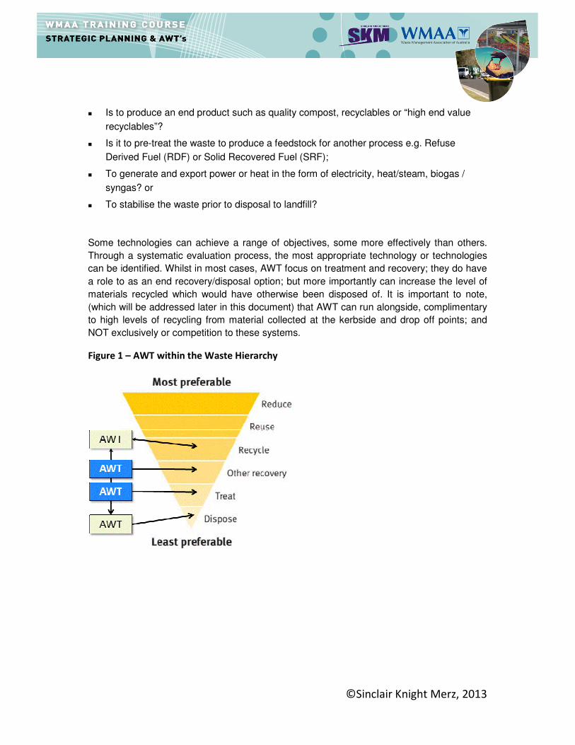
Some technologies can achieve a range of objectives, some more effectively than others.
Through a systematic evaluation process, the most appropriate technology or technologies
can be identified. Whilst in most cases, AWT focus on treatment and recovery; they do have
a role to as an end recovery/disposal option; but more importantly can increase the level of
materials recycled which would have otherwise been disposed of. It is important to note,
(which will be addressed later in this document) that AWT can run alongside, complimentary
to high levels of recycling from material collected at the kerbside and drop off points; and
NOT exclusively or competition to these systems.
Figure 1 – AWT within the Waste Hierarchy
©Sinclair Knight Merz, 2013
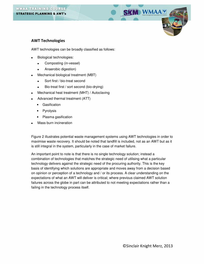
AWT Technologies
AWT technologies can be broadly classified as follows:
� Biological technologies:
� Composting (in-vessel)
� Anaerobic digestion)
� Mechanical biological treatment (MBT)
� Sort first / bio-treat second
� Bio-treat first / sort second (bio-drying)
� Mechanical heat treatment (MHT) / Autoclaving
� Advanced thermal treatment (ATT)
• Gasification
• Pyrolysis
• Plasma gasification
� Mass burn incineration
Figure 2 illustrates potential waste management systems using AWT technologies in order to
maximise waste recovery. It should be noted that landfill is included, not as an AWT but as it
is still integral in the system, particularly in the case of market failure.
An important point to note is that there is no single technology solution; instead a
combination of technologies that matches the strategic need of utilising what a particular
technology delivers against the strategic need of the procuring authority. This is the key
basis of identifying which solutions are appropriate and moves away from a decision based
on opinion or perception of a technology and / or its process. A clear understanding on the
expectations of what an AWT will deliver is critical; where previous claimed AWT solution
failures across the globe in part can be attributed to not meeting expectations rather than a
failing in the technology process itself.

©Sinclair Knight Merz, 2013
Figure 2 – AWT options for waste management practices
©Sinclair Knight Merz, 2013
Biological Technologies
Composting
In-Vessel Composting (IVC) is the aerobic decomposition of shredded and mixed organic
waste within an enclosed container. During aerobic decomposition, organic material is
converted into a residual solid, heat, carbon dioxide (CO2) and water (H2O) through microbial
respiration in the presence of oxygen, leaving a stabilised, or partially stabilised, residue that
is reduced in both weight and volume. The IVC process uses control systems that enable the
degradation of the organic material to be fully automated. Moisture, temperature and odour
can be regulated, and a stable output can be produced much more quickly than by using
outdoor windrow composting systems.
Windrow composting is a much simpler aerobic composting process than IVC. Long rows of
usually source segregated green waste are left to aerobically decompose in the open air.
The 'windrows', as they are named, are turned regularly to bring new material to the surface
and oxygenate the pile. There is no automation or temperature control. Windrows are
sometimes used as a final maturation step for material which has been processed through
IVC.
Composting is a relatively dry process, and it is typically used for materials with high solids
content - moisture content of 40 to 60%. Aerobic processes create large amounts of
biologically produced heat as microbes respire and are associated with high (thermophilic)
temperatures 55 - 70°C. Such high temperatures, if maintained and controlled, have the
advantage of sanitising the material (killing potentially pathogenic organisms) and drying the
material.
As the process progresses, heat, carbon dioxide and moisture are lost to the atmosphere,
leaving a mixture of woody fragments, microbes, and a complex decomposition by-product
called humus. This stable, dried organic mixture together with any non-biodegradable
material already in the process is known as 'compost' when produced from source
segregated organic waste; or 'compost-like output' when produced from non-source
segregated waste.
Open windrow composting is an established process in Australia, has been operating in
many locations around Australia. For example Remondis’ Cairncross facility near Port
Macquarie in NSW, has used tunnel composting since 2000 to treat garden organics and
sewage sludge and SITA’s BioWise facility in outer Perth has been treating garden organics
and sewage sludge in a partly enclosed batch composting process for around 10 years.
Over the last five or so years, several composting operations in Australia have introduced
integrated static aerated pile composting into their operations. Custom Composts (WA),
Peats Soil and Garden Supplies (SA) and Pinegro Products (VIC), for example, employ an
above ground mobile forced aeration system, while Jeffries (SA) have opted for a non-
mobile static aeration system.
©Sinclair Knight Merz, 2013
IVCs are now becoming more popular in Australia, with a recent development of an IVC
based in Dandenong Victoria. Should food waste collections become more commonplace in
Australia then it is likely that there will be a growing trend towards developing IVCs as they
help to manage odour and address other issues.
©Sinclair Knight Merz, 2013
Anaerobic Digestion (AD)
AD is a process where biodegradable material is broken down by the action of microbes in
the absence of oxygen. In Australia it has commonly been used in the treatment of sewage
sludge at waste water treatment works. In Europe it is widely used for the same purpose and
on farms to break down manure into slurry and a biogas. Increasingly the process is being
used to treat food waste.
Material is placed into an enclosed vessel and in controlled conditions the waste breaks
down into slurry or sludge (known as digestate), liquor and a biogas. AD is a wet process
used for materials with low solids content and high moisture contents (ranging between 60 to
95% moisture content by weight). Anaerobic processes may not produce sufficient amounts
of biologically produced heat to maintain optimal temperatures at 35°C to 40°C, and
additional heat may be required.
Due to the high moisture content of the waste material entering the process and the loss of
solids during digestion, the final digestate still contains a lot of moisture upon leaving the
process. This digestate can be mechanically separated into its solids (fibre) and liquid
(effluent) fractions. The dewatered fibre may be used directly on land as a soil improver
provided it meets appropriate regulatory criteria or is aerobically treated (matured through a
composting process) prior to its use. The liquid effluent may be recycled in the AD process,
used directly as a liquid fertiliser (if it meets the appropriate criteria), or used in subsequent
aerobic (composting) treatment of the fibre.
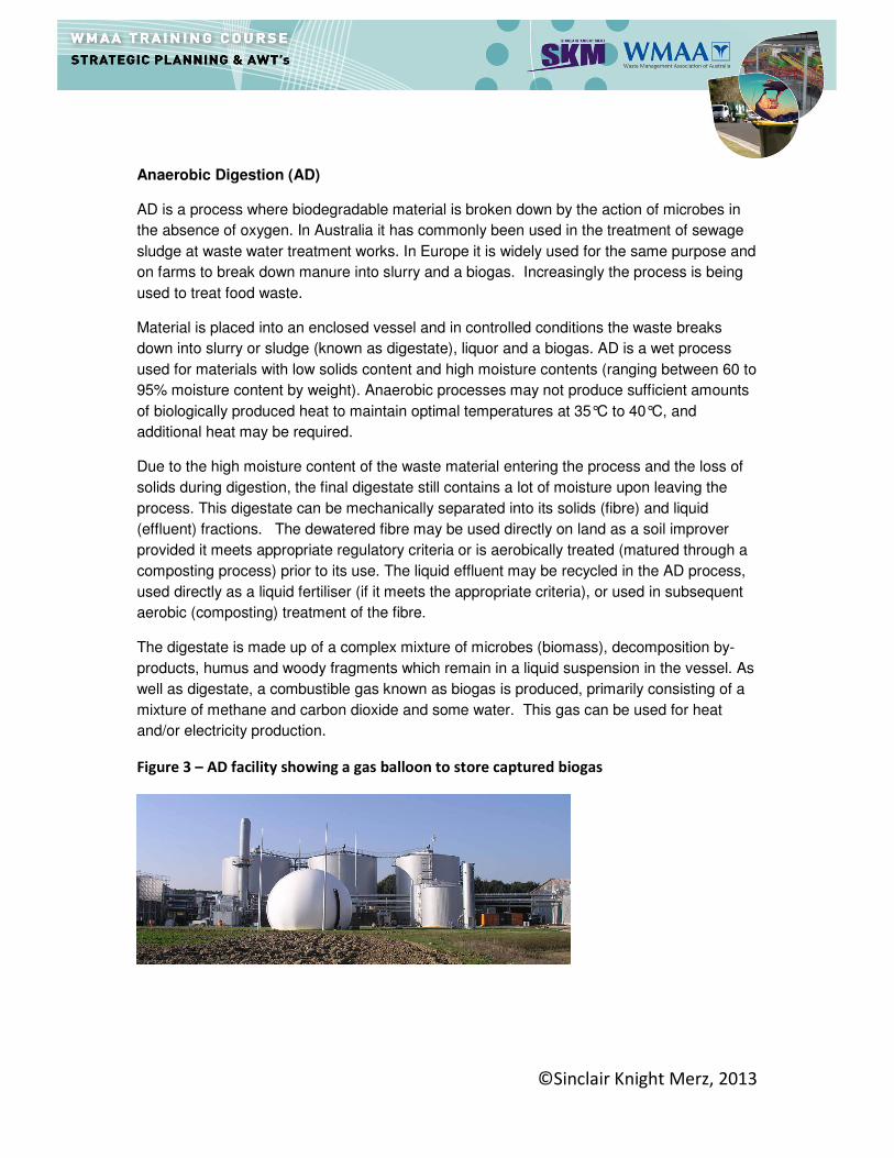
The digestate is made up of a complex mixture of microbes (biomass), decomposition by-
products, humus and woody fragments which remain in a liquid suspension in the vessel. As
well as digestate, a combustible gas known as biogas is produced, primarily consisting of a
mixture of methane and carbon dioxide and some water. This gas can be used for heat
and/or electricity production.
Figure 3 – AD facility showing a gas balloon to store captured biogas

©Sinclair Knight Merz, 2013
Mechanical and Biological Treatment Technologies
Mechanical biological treatment (MBT) is a generic term for an integration of several
processes and technologies commonly found in different waste management facilities such
as MRFs and biological treatment facilities using composting or anaerobic digestion. MBT
facilities can typically incorporate a number of different processes in a variety of
combinations to treat mixed general waste, designed to suit a range of purposes, strategic
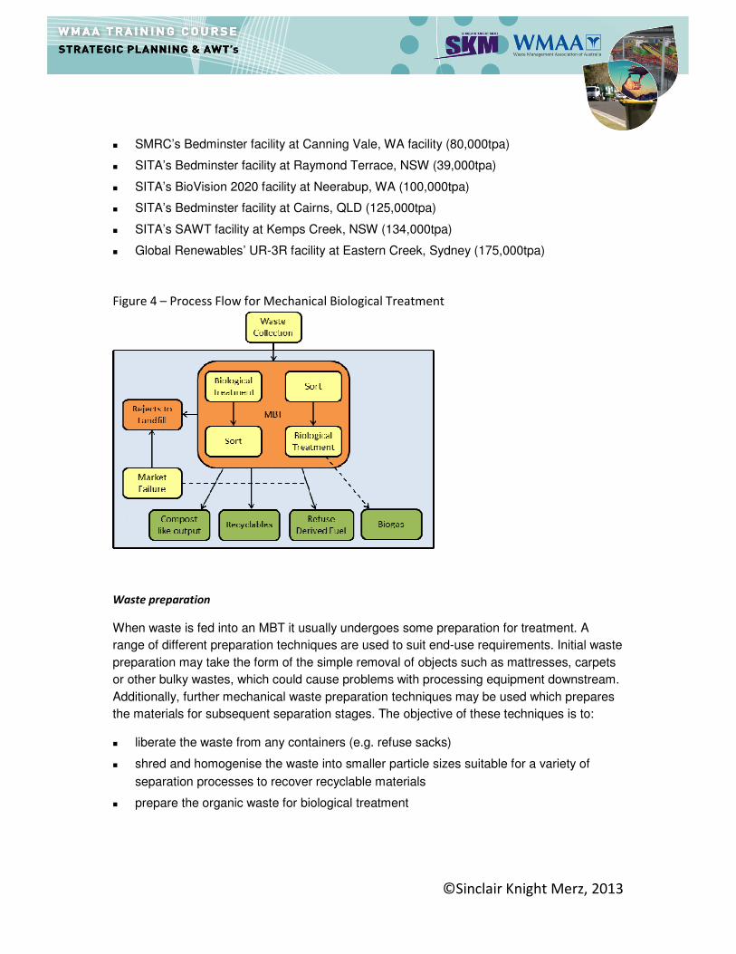
drivers and end market opportunities. Figure 4 presents a high level process flow of MBT
configuration.
MBT complements, but does not replace, other waste management technologies such as
recycling and composting as part of an integrated waste management system. The aim of all
MBT plants is to use mechanical and biological processes to prepare and separate waste
into useable fractions or render it more stable for deposit into landfill. A key advantage of
MBT is that it can be configured to achieve several different aims such as:
� Pre-treatment of waste going to landfill;
� Mechanical sorting of non-biodegradable mixed waste into materials for recycling and/or
energy recovery as refuse derived fuel (RDF);
� Diversion of biodegradable mixed waste going to landfill by:
� Reducing the mass of organic waste prior to landfill;
� Reducing the biodegradability of organic waste prior to landfill;
� Stabilisation of the organic fraction of mixed waste into a compost-like output (CLO)
for use on land;
� Conversion of the organic fraction into a combustible biogas for energy recovery;
and/or
� Drying the organic fraction of the waste to produce a refuse derived fuel (RDF).
However, it needs to be remembered that MBT is often not a solution in its own right. It is
used extensively in some European countries where there is a pre-requisite to treat ALL
waste before it is disposed of to landfill. Without this requirement it can be an expensive
approach to prepare material for combustion when compared to conventional energy from
waste facilities that can process mixed waste material directly. Conversely, if Advanced
Thermal Treatment methods are used, a MBT approach can help provide a consistent
feedstock for combustion.
The first MBT facilities were developed in Europe with the aim of reducing the environmental
impact of landfilling residual waste and in total there are over 330 MBT facilities in operation
throughout Europe. In Australia there are several MBT facilities treating mixed general
waste, these include:
� The MSW line at Remonidis’ Cairncross facility in Port Macquarie, NSW (20,000tpa)
©Sinclair Knight Merz, 2013
� SMRC’s Bedminster facility at Canning Vale, WA facility (80,000tpa)
� SITA’s Bedminster facility at Raymond Terrace, NSW (39,000tpa)
� SITA’s BioVision 2020 facility at Neerabup, WA (100,000tpa)
� SITA’s Bedminster facility at Cairns, QLD (125,000tpa)
� SITA’s SAWT facility at Kemps Creek, NSW (134,000tpa)
� Global Renewables’ UR-3R facility at Eastern Creek, Sydney (175,000tpa)
Figure 4 – Process Flow for Mechanical Biological Treatment
Waste preparation
When waste is fed into an MBT it usually undergoes some preparation for treatment. A
range of different preparation techniques are used to suit end-use requirements. Initial waste
preparation may take the form of the simple removal of objects such as mattresses, carpets
or other bulky wastes, which could cause problems with processing equipment downstream.
Additionally, further mechanical waste preparation techniques may be used which prepares
the materials for subsequent separation stages. The objective of these techniques is to:
� liberate the waste from any containers (e.g. refuse sacks)
� shred and homogenise the waste into smaller particle sizes suitable for a variety of
separation processes to recover recyclable materials
� prepare the organic waste for biological treatment

©Sinclair Knight Merz, 2013
Mechanical Separation
Following preparation, MBT plants used for mixed general waste typically include equipment
for sorting the mixed waste into different fractions using mechanical processes. Sorting the
waste allows an MBT process to separate different materials which are suitable for different
end uses. Potential end uses include material recycling, biological treatment, energy
recovery through the production of RDF and landfill. Separation technologies exploit varying
properties of the different materials in the waste, these properties include the size and shape
of different objects, their density, weight and response to magnetic and electrical fields.
Table 3 presents different separation methods utilised in MBTs.
Biological Treatment
The biological element of an MBT process can take place prior to or after mechanical sorting
of the waste. The primary biological processes utilised in MBT facilities are:
� Aerobic bio-drying
� Aerobic in-vessel composting
� Anaerobic digestion
Outputs and Markets
MBT plants can be configured to produce outputs relevant to the facility’s objectives. The
outputs will also be governed, to an extent, by the composition of the input waste which can
significantly vary depending on the level of source segregation at the household and
collection services available. Commonly, MBT facilities can produce a combination of some
of the following output streams, depending on their configuration:
Mechanical Outputs and Markets
� Dense Plastic Packaging i.e.– material reprocessors
� Paper and card – material reprocessors
� Textiles – material reprocessors
� Glass – material reprocessors
� Ferrous and non-ferrous metal – material reprocessors
©Sinclair Knight Merz, 2013
Biological Outputs and Markets
� Biogas – energy markets
� Electricity – energy markets
� RDF – energy recovery facilities
� Process Water – onsite or offsite treatment
� Residues – landfill or incineration
� Compost-like-output – landfill daily cover and land reclamation
The markets for the outputs from MBT usually vary between regions and can also alter
throughout the life of a contract. An important point to note is that if no market exists, the
material will go to landfill. Given that a significant quantity of material leaving an MBT
process (by weight) is RDF, CLO or dirty recyclable materials, this can present a risk if
suitable markets are not secured or these realities not understood.

©Sinclair Knight Merz, 2013
Mechanical Heat Treatment Technologies
Mechanical Heat Treatment (MHT) is a term used to describe technologies that use steam
based thermal treatment, with or without pressure, in conjunction with mechanical
processing. There are two main types of facility that use mechanical heat treatment:
Heat Treatment process Description
Type 1: Autoclaving – batch, steam processing in a vessel under the action of pressure
Waste is subjected to steam under pressure, followed by mechanical sorting and separation of the sterilised waste
Type 2: Continuous heat treatment in a vessel, not under the action of pressure eg rotary kiln
Waste is dried using externally applied heat, followed by mechanical sorting and
separation of the sanitised waste
The purpose of these processes is to separate a mixed general waste or commercial waste
stream into several component parts, in order to provide further options for recycling,
biological treatment and energy recovery. The processes sanitise the waste by destroying
bacteria and reduce the moisture content through drying.
The waste feedstock material can be mechanically treated prior to heat treatment through:
� Screening – to remove large items
� Shredding – to achieve an even particle size distribution
� Addition of water – to improve the homogeneity of the waste
This process is generally targeted to remove particular contaminants such as bulky waste
items and household batteries.
Both types of heat treatment (autoclave and rotary kiln) apply temperatures in the range of
120-170 ºC through the introduction of pumped hot air which is sufficient to destroy bacteria
and viruses present in the waste. This has benefits in terms of storage, transport and
handling of the outputs as they are sanitised and are free from the biological activity that
may give rise to odour problems. There is also a significant volume reduction of the waste.
The resulting outputs of the heat treatment are:
� ‘hard’ recyclables including plastics, glass and cans, which some processes claim have
been cleaned through the process
� fibrous material from the breakdown of paper, card and green/kitchen waste
constituents, potentially suitable for biological treatment or for generating a solid
recovered fuel (SRF) which is essentially a refined form of RDF for intended use in at a

©Sinclair Knight Merz, 2013
particular energy generating facility. In Europe SRF has a defined standard and is a
saleable, desired product.
� a reject fraction suitable for disposal to landfill
An autoclave system treats batches of feedstock material within a sealed vessel operating
under a typical pressure of between 5-7 bar. The vessel rotates to mix the material and it
usually remains in the vessel for between 1 and 2 hours. The heat and pressure of the
autoclave process ‘cooks’ the waste and provides the following functions:
� Organic and other biodegradable materials are broken down into a fibre, sometimes
referred to as ‘floc’
� Labels attached to glass bottles and tins are removed as the glue disintegrates under
the action of the heat
� Plastics are softened, and labels are removed. Certain types of plastic are deformed by
the heat, but remain in a recognisable state, where as other plastics soften completely
forming hard balls of dense plastic
Rotary kiln systems operate continuously, with waste passing through the vessel. Water is
added to reach pre-determined moisture levels of around 35%. The vessel is kept under
atmospheric pressure and the waste is rotated as a hot air stream passes through the
vessel. The residence time of the waste in the heat vessel is typically up to 45 minutes, after
which the treated waste is typically removed for subsequent mechanical processing.
Figure 5 presents a high level process flow of MHT configuration.

©Sinclair Knight Merz, 2013
Figure 5 – Process Flow for Mechanical Heat Treatment
Outputs
Materials Separation
The materials removed from the MHT vessels are potentially recyclable and include glass,
metals, plastics and a fibre (floc).
MHT systems invariably utilise a number of separation techniques to extract the various
recyclable components following the heat treatment process. These are likely to be similar to
the mechanical separation technologies used in MBT systems. A high-quality ferrous and
non- ferrous metal stream, cleaned of labels and foodstuffs is always extracted for recycling.
Some systems may also extract a glass and aggregate stream, and a plastics stream for
recycling. As with any waste treatment process there will be a reject fraction which is sent to
landfill.
Fibre
The fibre comprises the putrescible, lignin and cellulose elements of the waste stream
(organics, paper, card etc). There are a number of potential options available for the
remaining fibre after removal of recyclates, such as use as a raw material for a recycled
product, refined as a fuel, or biologically processed. However, no commercial markets
currently exist for these materials.

©Sinclair Knight Merz, 2013
An emerging area of potential recycling from some MHT systems is the use of the fibre in
recycling applications.
Work is being undertaken to evaluate use of the fibre as a raw material for example by
mixing the fibre together with crushed shale and a resin to manufacture composite products
such as floor tiles. Other options may include mixing with cement to produce building
products and washing the fibre to extract the long cellulose fibres suitable for paper-making.
However, the market for recycled products made with fibre from MHT processes is not yet
established and is subject to ongoing development.
The fibre may also be combusted as a RDF to release the energy contained within. The fibre
is typically of a fine homogenous nature consisting of broken down organic matter; paper
and card; and provides a consistent feedstock for onward thermal combustion.
Fibre produced by an MHT plant is visibly different to an RDF produced by an MBT plant.
The predominant difference is that RDF from a MBT plant usually contains recognisable
components, including plastic, paper/card and may also contain organic material from
certain systems. It may also be less homogenous in nature than RDF from MHT. There may
be different operational requirements regarding thermal combustion of each of these types of
RDF.
The second option is to biologically process the fibre. Since the autoclave process is a
sanitisation process that kills most of the microbes present in the waste, the fibre may need
to be ‘seeded’ with microbes (e.g. mixed with material that has already undergone
biological treatment) to accelerate the onset of the biological process . Either composting or
anaerobic digestion techniques could be used.
©Sinclair Knight Merz, 2013
Advanced Thermal Treatment (ATT) Technologies
Advance Thermal Treatment (ATT) technologies are primarily those that employ pyrolysis
and / or gasification to process mixed waste.
The gasification and pyrolysis of solid materials is not a new concept. It has been used
extensively to produce fuels such as charcoal, coke and town gas. Charcoal and coke are
produced by the pyrolysis of wood and coal respectively and town gas is a combustible gas
produced by the gasification of coal in the presence of air and steam.
It is only in recent years that pyrolysis and gasification has been commercially applied to the
treatment of mixed waste streams, though a number of large scale plants have been built
and are in operation in Europe, North America and Japan. Examples in Australia included
the SWERF plant in Wollongong that operated between 2001-2005 and the New Energy
gasification facility which is being developed in Western Australia.
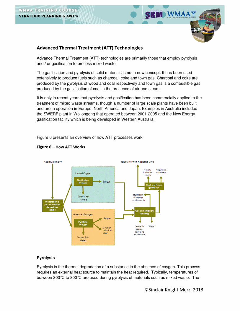
Figure 6 presents an overview of how ATT processes work.
Figure 6 – How ATT Works
Pyrolysis
Pyrolysis is the thermal degradation of a substance in the absence of oxygen. This process
requires an external heat source to maintain the heat required. Typically, temperatures of
between 300°C to 800°C are used during pyrolysis of materials such as mixed waste. The

©Sinclair Knight Merz, 2013
products produced from the pyrolysis of materials are a solid residue and synthetic gas. The
solid residue (sometimes described as a char) is a combination of non- combustible
materials and carbon. The char retains a calorific value and can be used as a fuel, for
example as a feedstock within a gasifier. The syngas is a mixture of gases, including carbon
monoxide, hydrogen, methane and a broad range of other volatile organic compounds
(VOCs). A proportion of these can be condensed to produce oils, waxes and tars. The
syngas typically has a net calorific value (NCV) of between 10 and 20 MJ/Nm3. If required,
the condensable fraction can be collected, potentially for use as a liquid fuel (pyrolysis oil) or
in a chemical application, by cooling the syngas.
The calorific value of syngas from pyrolysis and gasification is far lower than natural gas,
which has a NCV of around 38 MJ/Nm3.
Gasification
Gasification can be seen as mid-way between pyrolysis and combustion in that it involves
the partial oxidation of a substance. This means that oxygen is added but the amounts are
not sufficient to allow the fuel to be completely oxidised and therefore full combustion does
not occur. The temperatures employed are typically above 750°C. The main product is a
syngas, which contains carbon monoxide, hydrogen and methane. Typically, the gas
generated from gasification will have a calorific value (NCV) of 4 - 10 MJ/Nm3. The other
main product produced by gasification is a solid residue of non-combustible materials (ash)
which contains a relatively low level of carbon.
Differences between Pyrolysis, Gasification and Incineration
There are a variety of features promoted to differentiate advanced thermal treatment from
conventional incineration technologies. These include:
� The potential smaller scale of ATT processes in comparison to mass burn incineration,
which may facilitate local use of the output heat and electricity;
� Reduced emissions from ATT processes may mean that abatement costs are reduced
(although all the processes must meet the same emissions standards); and
� The potential to use the syngas as a fuel could enable higher energy efficiency to be
achieved through ATT.
Outputs from Advanced Thermal Treatment Technologies
ATT processes produce a gas (usually for energy recovery) and a solid residue (ash or
char). The systems are designed with mechanical preparation and sorting equipment at the
front end to extract recyclates, unless the facility is designed to take prepared waste or RDF.
Table 1 summarises the key outputs from ATT processes.
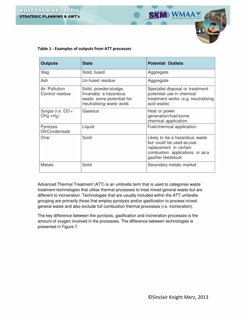
©Sinclair Knight Merz, 2013
Table 1 - Examples of outputs from ATT processes
Outputs
State
Potential Outlets
Slag Solid, fused Aggregate
Ash Un-fused residue Aggregate
Air Pollution Control residue
Solid, powder/sludge. Invariably a hazardous waste; some potential for neutralising waste acids
Specialist disposal or treatment potential use in chemical treatment works (e.g. neutralising acid waste)
Syngas (i.e. CO + CH4 +H2)
Gaseous Heat or power generation/fuel/some chemical application
Pyrolysis Oil/Condensate
Liquid Fuel/chemical application
Char Solid Likely to be a hazardous waste but could be used as coal replacement in certain combustion applications or as a gasifier feedstock
Metals Solid Secondary metals market
Advanced Thermal Treatment (ATT) is an umbrella term that is used to categorise waste
treatment technologies that utilise thermal processes to treat mixed general waste but are
different to incineration. Technologies that are usually included within the ATT umbrella
grouping are primarily those that employ pyrolysis and/or gasification to process mixed
general waste and also exclude full combustion thermal processes (i.e. incineration).
The key difference between the pyrolysis, gasification and incineration processes is the
amount of oxygen involved in the processes. The difference between technologies is
presented in Figure 7.
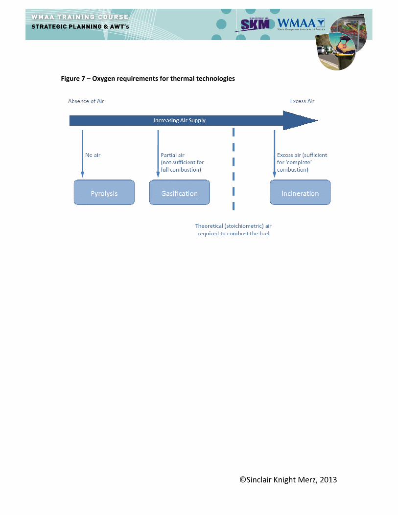
©Sinclair Knight Merz, 2013
Figure 7 – Oxygen requirements for thermal technologies

©Sinclair Knight Merz, 2013
Energy from Waste (EfW) and Incineration
Conventional thermal treatment of mixed waste streams is a mature and well established
technology in Europe, North America and Asia. The terminology that is used includes
incineration or 'energy from waste' or ‘waste to energy’. The term incineration will be used
throughout this manual rather than the broad term ‘energy from waste’ or ‘waste to energy’
which could also include technologies such as anaerobic digestion, pyrolysis and gasification
which all produce energy from waste.
Incineration involves the combustion of typically unprepared (raw or residual) mixed waste.
However less frequently, plants can be built to accept prepared waste in the form of Refuse
Derived Fuel (RDF).
To allow the complete combustion of the waste to take place an excess supply of oxygen is
required to fully oxidise the fuel and the waste is moved into and through the furnace either
using a moving grate, or a 'fluidised bed' of sand, or an oscillating kiln. Typically,
incineration plant combustion (flame) temperatures are in excess of 850°C and the waste is
converted into carbon dioxide and water and any non-combustible materials (e.g. metals,
glass) remain as a solid residue, known as bottom ash, which contains a small amount of
residual carbon.
Incinerators are designed to burn the waste as efficiently as possible, usually recovering
energy. Heat released from the combustion of waste is recovered and used to generate
electricity and/or to provide steam or hot water. The amount of waste needing disposal
following combustion is reduced by approximately 90%, reducing the need for landfill.
The heat created by the combustion, can be used to produce electricity or used for local
heating. In addition the residues from air pollution control (APC), including fly ash, are
typically sent to a hazardous waste landfill, and the bottom ash can either be recycled or
disposed of to landfill.
Process Description
Plant designs and configurations differ considerably between technology providers.
However, an incinerator with energy recovery will typically comprise the following key
elements:
Waste Reception Area
The waste is usually delivered via a waste collection vehicle and tipped into a bunker within
an enclosed building. Within the bunker the waste is mixed by on overhead crane. The
mixing is required to blend the waste to ensure that the energy input (calorific value of the
waste feed) to the combustion chamber is as even as possible. The mixed general waste is
grabbed by a crane and dropped in to a feedstock hopper which feeds waste in a controlled
manner into the combustion chamber.
©Sinclair Knight Merz, 2013
Furnace
Once inside the furnace, the waste is usually heated to temperatures in excess of 850°C
using high oxygen levels to aid full combustion of the waste. This combustion process
releases carbon dioxide and other gases and leaves a non-combustible residue Incinerator
Bottom Ash (IBA).
Differences in combustion technology in terms of the furnace design and the way in which
the waste is agitated to ensure full combustion, can be tailored to accommodate variations in
design feedstock and can help maximise the proportion of feedstock that is combusted.
Energy recovery
The standard approach for the recovery of energy from the incineration of mixed general
waste is to utilise the combustion heat through a boiler to generate steam. Of the total
available energy in the waste, up to 80% can be retrieved in the boiler to produce steam.
The steam can be used for the generation of power via a steam turbine and/or used for
heating or cooling by absorption. An energy recovery plant that produces both heat and
power is commonly referred to as a Combined Heat and Power (CHP) Plant and this is the
most efficient option overall for utilising recovered energy from waste via a steam boiler.
Bottom ash and metal handling area
Unburnt material which passes out of the furnace includes non-combustible material such as
glass, metals and ash. This material, known as Incinerator Bottom Ash (IBA), is usually
quenched in water with subsequent metals removal by magnets and eddy-current
separators. The remaining IBA is commonly then collected and recycled on or off site.
Emissions control
The gases produced through combustion typically pass through a combination of Air
Pollution Control (APC) treatment stages to remove oxides of sulphur and nitrogen by
injecting lime and carbon into the gas stream. The gases then typically pass through a
physical sieving stage to remove particulates, before entering the atmosphere from a stack /
chimney. Particulate residues from this APC process are known as Air Pollution Control
Residues and are hazardous in nature.
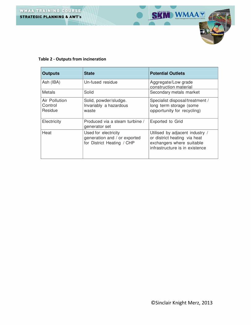
Outputs from Mass Burn Incineration
Incinerators generate significant amounts of heat through the combustion process which is
utilized for energy recovery purposes. In addition, there are solid residues arising from the
combustion of the waste and also the gas clean up processes. These outputs are
summarised in Table 2.
©Sinclair Knight Merz, 2013
Table 2 - Outputs from incineration
Outputs
State
Potential Outlets
Ash (IBA) Un-fused residue Aggregate/Low grade construction material
Metals Solid Secondary metals market
Air Pollution Control Residue
Solid, powder/sludge. Invariably a hazardous
waste
Specialist disposal/treatment / long term storage (some
opportunity for recycling)
Electricity Produced via a steam turbine / generator set
Exported to Grid
Heat Used for electricity generation and / or exported for District Heating / CHP
Utilised by adjacent industry / or district heating via heat exchangers where suitable infrastructure is in existence
©Sinclair Knight Merz, 2013
The Impact of Collection Strategies on the Mixed Residual (General) Waste and
AWT Operation
1What is General (Residual) Waste
There are a variety of definitions of waste2. Residual Waste in the context of kerbside household
waste collections can be a term that is used to describe the material collected within the ‘normal
refuse bins or bags’ and not self-hauled or subject to other collections at the kerbside such as for
recycling, composting, .
The composition of waste can vary significantly for a range of reasons such as demographics,
economics, climate and so on. The composition of residual waste is even more variable between
authorities (normally Councils), depending on the type and effectiveness of kerbside recycling and
green waste schemes.
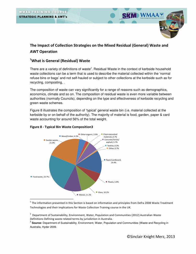
Figure 8 illustrates the composition of ‘typical’ general waste bin (i.e. material collected at the
kerbside by or on behalf of the authority). The majority of material is food, garden, paper & card
waste accounting for around 56% of the total weight.
Figure 8 - Typical Bin Waste Composition3
1 The information presented in this Section is based on information and principles from Defra 2008 Waste Treatment
Technologies and their implications for Waste Collection Training course in the UK.
2 Department of Sustainability, Environment, Water, Population and Communities (2012) Australian Waste
Definitions Defining waste related terms by jurisdiction in Australia. 3 Source: Department of Sustainability, Environment, Water, Population and Communities (Waste and Recycling in
Australia, Hyder 2009.
Paper/cardboard,
14.4%
Plastic, 5.9%
Glass, 10.2%
Metals, 11.2%
Food waste, 23.7%
Garden waste,
21.0%
Wood/timber, 4.2%Other organic, 2.0% Clean excavated
materials, 0.7%
Concrete/ bricks/
asphalt, 5.7%
Textiles, 0.3%
Other, 0.7%
©Sinclair Knight Merz, 2013
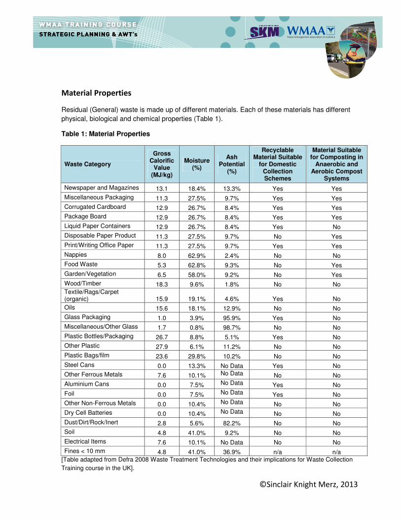
Material Properties
Residual (General) waste is made up of different materials. Each of these materials has different
physical, biological and chemical properties (Table 1).
Table 1: Material Properties
Waste Category
Gross Calorific
Value (MJ/kg)
Moisture (%)
Ash Potential
(%)
Recyclable Material Suitable
for Domestic Collection Schemes
Material Suitable for Composting in
Anaerobic and Aerobic Compost
Systems
Newspaper and Magazines 13.1 18.4% 13.3% Yes Yes
Miscellaneous Packaging 11.3 27.5% 9.7% Yes Yes
Corrugated Cardboard 12.9 26.7% 8.4% Yes Yes
Package Board 12.9 26.7% 8.4% Yes Yes
Liquid Paper Containers 12.9 26.7% 8.4% Yes No
Disposable Paper Product 11.3 27.5% 9.7% No Yes
Print/Writing Office Paper 11.3 27.5% 9.7% Yes Yes
Nappies 8.0 62.9% 2.4% No No
Food Waste 5.3 62.8% 9.3% No Yes
Garden/Vegetation 6.5 58.0% 9.2% No Yes
Wood/Timber 18.3 9.6% 1.8% No No
Textile/Rags/Carpet (organic) 15.9 19.1% 4.6% Yes No
Oils 15.6 18.1% 12.9% No No
Glass Packaging 1.0 3.9% 95.9% Yes No
Miscellaneous/Other Glass 1.7 0.8% 98.7% No No
Plastic Bottles/Packaging 26.7 8.8% 5.1% Yes No
Other Plastic 27.9 6.1% 11.2% No No
Plastic Bags/film 23.6 29.8% 10.2% No No
Steel Cans 0.0 13.3% No Data Yes No
Other Ferrous Metals 7.6 10.1% No Data No No
Aluminium Cans 0.0 7.5% No Data Yes No
Foil 0.0 7.5% No Data Yes No
Other Non-Ferrous Metals 0.0 10.4% No Data No No
Dry Cell Batteries 0.0 10.4% No Data No No
Dust/Dirt/Rock/Inert 2.8 5.6% 82.2% No No
Soil 4.8 41.0% 9.2% No No
Electrical Items 7.6 10.1% No Data No No
Fines < 10 mm 4.8 41.0% 36.9% n/a n/a
[Table adapted from Defra 2008 Waste Treatment Technologies and their implications for Waste Collection
Training course in the UK].
©Sinclair Knight Merz, 2013
Different materials will be suitable for:
� Combustion and energy production;
� Technology treatment processes;
� Existing recycling markets; and
� New/alternative markets.
The residual waste may be assessed for a range of properties to test its suitability for different
treatment and recovery options. These could include:
� Gross Calorific Value (GCV) - The number of heat units obtained by the complete
combustion of the material. This is measured in Mega Joules per Kilogram of waste (MJ/Kg).
The GCV includes the heat/energy from steam when the water lost during the process is
condensed.
� Net Calorific Value (NCV) - The number of heat units obtained by the complete combustion of
the material excluding the heat/energy gained from steam loss due to water being condensed.
Within a typical Energy from Waste (EfW) process the additional energy from the condensing
of water to steam is lost through the stack and the energy not recovered though the
combustion process.
� Moisture - Moisture is defined as the weight lost (expressed as a percentage) when a sample
of solid waste is dried to a constant weight at a temperature of 105oC.
� Ash - The amount of inorganic residue remaining after ignition of combustible substances
determined by standard testing methods.
� Proportion of remaining recyclable/compostable material.
©Sinclair Knight Merz, 2013
The Conundrum
One of the focuses of recyclables and similar collection systems is to collect as much material as
is possible at the kerbside to make schemes cost effective and encourage households to
participate.
A conflict of interest situation could easily arise where an owner / operator of an Alternative Waste
Treatment (AWT) facility could be targeting the same materials to improve performance for very
different reasons. For example, an authority may want to collect as many newspaper and plastics
bottles at the kerbside as possible as the weight contributes to their recycling figures. However an
AWT owner / operator would also like these materials in their feedstock as the moisture content is
low and Gross Calorific Value (GCV) high, therefore potentially resulting in higher thermal
efficiencies at a thermal plant or material recovery from an MBT process.
Understandably the collection authority (council) and the AWT owner / operator will seek guidance
from each other so their system can be configured accordingly. The best way of determining the
most appropriate solution is through a partnership process and open dialogue between the two.
Ultimately, the best AWT solution will be influenced by the composition and chemical and
biological properties of the residual waste delivered.
When assessing the appropriate combination of collection systems and treatment and disposal
facilities there should be an appreciation that within each authority there will be:
� Different composition of residual (general) waste;
� Different coverage of kerbside collection facilities;
� Different availability/composition/quantity of materials self hauled to transfer stations;
� Different scheme designs that will target a range of materials with varying yields and affect the
availability of material within the systems and the quantities diverted into each system
� Different levels of performance on each of the kerbside schemes operating in terms of:
� How many people use a service (measured as participation rate);
� How often they use it (measured as set out rate);
� How well they use a scheme (measured by different performance indicators such as
recognition rate, capture rate and contamination rate).
All of these factors combined will affect the types and quantities of materials in the residual waste
that require treatment and the bulk mixture of these materials could affect the feedstock required
by a particular type of waste treatment/disposal facility.
©Sinclair Knight Merz, 2013
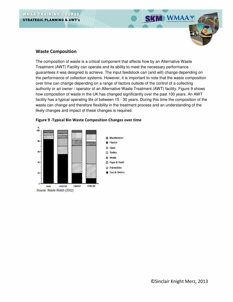
Waste Composition
The composition of waste is a critical component that affects how by an Alternative Waste
Treatment (AWT) Facility can operate and its ability to meet the necessary performance
guarantees it was designed to achieve. The input feedstock can (and will) change depending on
the performance of collection systems. However, it is important to note that the waste composition
over time can change depending on a range of factors outside of the control of a collecting
authority or an owner / operator of an Alternative Waste Treatment (AWT) facility. Figure 9 shows
how composition of waste in the UK has changed significantly over the past 100 years. An AWT
facility has a typical operating life of between 15 - 30 years. During this time the composition of the
waste can change and therefore flexibility in the treatment process and an understanding of the
likely changes and impact of these changes is required.
Figure 9 -Typical Bin Waste Composition Changes over time
©Sinclair Knight Merz, 2013
Impact of Collection Systems on AWT
In order estimate the impact of a collection scheme on the general (residual) waste requires
an understanding of the likely performance of the collection scheme. This can be measured
in two ways:
1) “Presentation” of the containers by households
2) “Efficiency” of households in using the containers
These principals are discussed in detail in Module 4. However they are important to consider
when designing an AWT. Waste streams are not constant and can vary over time. The
design of an AWT will therefore need to be flexible to accommodate such a varying waste
stream. In some cases the facility will still be able to operate, but will not be as effective as if
operating within a specified operating range. Other facilities will be more sensitive to the
material going into the facility i.e. input feedstock.
Impact on Energy from Waste (EfW) and Incineration
Incinerators can be designed to burn almost any general waste it receives. However, their
efficiency, the pre-processing of the waste, the combustion technology and clean-up of the
resulting combustion products will be impacted by the composition of the waste feedstock.
Therefore, the composition of the waste feedstock must be clearly defined and the
implications of the collection strategy assessed.
These impacts can be categorised as follows:
1) Energy content of the waste – Increasing or reducing moisture in the waste will
change energy content of the waste. The energy content will also be influenced by the
percentage content of each waste fraction. For example, glass and metals are non-
combustible and will not provide an energy input. Plastics will have high energy contents
as these are typically derived from oil. Biomass derived materials such as paper and
card will also have relatively high energy content. In contrast, organic materials (kitchen
and garden wastes) will have low energy content (due to their high moisture content).
In addition to impacting on efficiency, increasing moisture content will also influence the
design of the combustion system. For example, the fuel handling system and grate size
will increase.
2) Waste particle size - The particle waste size will determine if pre-treatment is required.
Large bulky waste will need to be size reduced e.g. by shredding, or removed before
being combusted.
3) Trace components - The clean up process (i.e. flue gas treatment) represents a
significant proportion of the plant’s capital cost. Removal of trace components such as
heavy metals, sulphur and chlorine will impact heavily on gas clean-up requirements,
i.e. acid gas and heavy metal removal from the flue gases.
©Sinclair Knight Merz, 2013
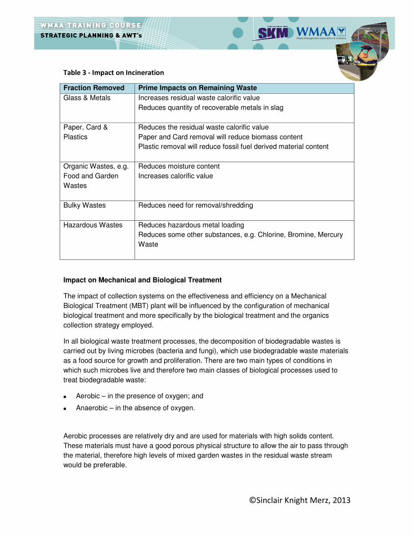
Table 3 - Impact on Incineration
Fraction Removed Prime Impacts on Remaining Waste
Glass & Metals Increases residual waste calorific value
Reduces quantity of recoverable metals in slag
Paper, Card &
Plastics
Reduces the residual waste calorific value
Paper and Card removal will reduce biomass content
Plastic removal will reduce fossil fuel derived material content
Organic Wastes, e.g.
Food and Garden
Wastes
Reduces moisture content
Increases calorific value
Bulky Wastes Reduces need for removal/shredding
Hazardous Wastes Reduces hazardous metal loading
Reduces some other substances, e.g. Chlorine, Bromine, Mercury
Waste
Impact on Mechanical and Biological Treatment
The impact of collection systems on the effectiveness and efficiency on a Mechanical
Biological Treatment (MBT) plant will be influenced by the configuration of mechanical
biological treatment and more specifically by the biological treatment and the organics
collection strategy employed.
In all biological waste treatment processes, the decomposition of biodegradable wastes is
carried out by living microbes (bacteria and fungi), which use biodegradable waste materials
as a food source for growth and proliferation. There are two main types of conditions in
which such microbes live and therefore two main classes of biological processes used to
treat biodegradable waste:
� Aerobic – in the presence of oxygen; and
� Anaerobic – in the absence of oxygen.
Aerobic processes are relatively dry and are used for materials with high solids content.
These materials must have a good porous physical structure to allow the air to pass through
the material, therefore high levels of mixed garden wastes in the residual waste stream
would be preferable.

©Sinclair Knight Merz, 2013
During anaerobic digestion (AD), biodegradable material is converted into a “biogas”,
containing methane (CH4) and carbon dioxide (CO2) and water through microbial
fermentation in the absence of oxygen, leaving a partially stabilised wet organic mixture.
There are two main classifications of AD techniques: ‘wet’ and ‘dry’. In essence, ‘wet’ AD
systems process more liquid materials (≥85% moisture), whereas ‘dry’ AD processes are
used to treat drier materials (≤80% moisture) ranging from thick slurry to a wet solid.
For a wet AD process, a higher proportion of kitchen waste in the residual waste would be
more suitable in order to maximise the production of biogas from the organic fraction.
Maximising the production of biogas could be a key factor in the economic viability of a
treatment technology.
Dry AD can tolerate higher levels of physical contaminants and therefore a residual waste
stream with higher level of dry matter, such as mixed garden waste, is likely to be suitable
for a dry AD system.
Therefore if collection authorities employ an effective kitchen only service, the residual waste
in more likely to have reduced proportions of high moisture food waste. Therefore an MBT
utilising dry AD or aerobic treatment would potentially be a more economic and
environmentally beneficial option for residual waste treatment. Conversely if a garden only
collection service was undertaken, this would suggest that an MBT utilising anaerobic
digestion would be preferable over aerobic.
Economically and environmentally, AD could be more favourable than composting with high
collection rates of kitchen waste, because of higher revenue from electricity and heat
production as well as maximising the biomass fraction as a resource.
Impact on Mechanical Heat Treatment
Mechanical Heat Treatment (MHT), often referred to as Autoclaveing, is used to describe
configurations of mechanical and thermal (including steam) based technologies. The generic
purpose of these processes is to separate a mixed waste stream into several component
parts, to give further options for recycling, recovery and in some instances biological
treatment.
Although the emphasis is configuring the MHT to meet the objectives of the markets, this
may be facilitated or hindered by the collection systems in place. Some systems are
designed to produce RDF to a particular fuel specification tailored to a specific market
demand. If however the proportion and tonnage of biomass is reduced through greater
efficiencies in the collection system it could have detrimental impacts on the markets for the
RDF produced by the MHT.
©Sinclair Knight Merz, 2013
In Conclusion………Waste properties’ effect on AWT
Different collection strategies may not significantly affect the overall chemical and biological
properties of the waste to the extent that these affects would significantly influence the
residual (General) waste treatment choice. Some facility designs may be more tolerant than
others to variations in composition. Targeting materials at the kerbside is more likely to affect
the total weight of material being diverted. The combined over or under estimation of
household performance on a kerbside dry or organic collection scheme from a number of
authorities participating in a regional AWT facility could significantly affect the treatment
facility capacity required.
Understanding the likely impact of a range of different collection schemes and proposed
strategies can assist in predicting the capacity required for each segregated waste stream
and the remaining residual flows to ensure that the procured facility size is appropriate. A
facility that is too small provides insufficient capacity, while one that is too large increases
the processing costs.
The revised composition of material may not significantly change if the typical mix of organic
and dry recyclable materials (e.g. paper, card, cans, glass, plastic bottles, textiles) are
targeted at the kerbside.
Extensive coverage and high performing collection schemes that target specific materials
may result in changes in the overall biodegradability or the energy content of the waste. For
example:
� the reduction of wet organic waste could provide a higher bulk calorific value of the
residual waste.
� a successful kerbside and drop off system for glass and cans could further increase the
energy value per kg of waste.
©Sinclair Knight Merz, 2013
Procuring an Alternative Waste Treatment (AWT)
Pre-Procurement Activity
Before procuring a new waste treatment facility the council (or private sector company in the
case of a merchant facility) will need to have a strong understanding of the following issues:
� The reason(s) why a facility is needed
� The quantity of waste that is required to be treated by the facility (usually in tonnes of
waste per annum (tpa))
� The composition of the waste stream
� Reliable waste flow modeling data (i.e. growth or decrease in waste quantities over time)
� The potential impact of local kerbside recycling and waste prevention schemes
� Local demographics (is the local population likely to increase or decrease over the
lifetime of the facility)
� Local sensitivities to particular technology types (e.g. are local residents likely to be
hostile to mass burn incineration, or concerned about odours from composting
facilities?).
Probably the main issue faced in procuring new technologies is that of the degree of certainty that it can deliver the desired outcomes. The newer the technology, the less likely it is to have a track record and hence there will be what is termed 'bankability' issues. The procurement process should be structured to tackle these issues, evaluating the risks, including the bankability of the scheme.
Bankability should be seen as a series of tests which the proposed service and technology are put through. As the proposals pass these tests the bankability increases. The type of tests that the proposal has to pass are those such as site selection, gaining planning permission or consent to operate, successful commissioning of a similar plant processing similar waste elsewhere, or securing performance bonds from the technology provider.
©Sinclair Knight Merz, 2013
Stakeholders in the Technology Selection and Procurement Process
Irrespective of whether a new waste treatment facility is being selected and procured by a
local council or a private sector company, there are a number of stakeholders who will seek
to take an active part in the decision-making process. These stakeholders include:
� Local residents (particularly those who live near the proposed site(s) upon which the
facility(s) are to be developed)
� Local landowners – particularly if there are sensitive land uses / industries nearby (e.g.
food processing plants)
� Local councils and contractors who will be responsible for delivering waste to the new
facility(s)
� Government authorities that have responsibility for issuing consents/approvals/licenses
for facilities – e.g. State Environmental Protection Agencies
� Banks and equity providers who will be responsible for providing the capital funding for
the new facility(s)
� Technology providers
� Consultants (technical, financial, and legal)
� Civil, mechanical and electrical engineering contractors
� Non-governmental organisations – these can include green groups, industry
associations and local resident action groups that may form to oppose/support a
proposed facility.
Effective stakeholder engagement is a fundamental aspect of delivering new waste
treatment facilities. Opposition to proposed facilities can quickly develop and can provide
significant risk and delays to the decision-making process and the development of the
facility(s).

©Sinclair Knight Merz, 2013
The Cost of Waste Treatment Facilities
An important consideration when deciding whether to invest in a new technology is the
question of cost. How much will it cost the council (or tax payer) or private sector provider to
build and operate a new plant? How much will the council have to pay for a new waste
service? How does this compare to the cost of sending waste to landfill? Can the council
afford to develop this technology? Unfortunately these are not easy questions to answer as
the range and quality of information on costs and prices is variable.
Published cost data on the relative costs of different waste management technologies are
infrequent and variable. The amount of cost data available has increased over recent years,
but is not easily comparable and it is thus difficult to present generic costs for each
technology. Costs will be influenced by issues such as location, size of plant, type of
technology, contractor, amount of waste handled, length of contract and levels of risk
involved. They are most likely to be higher than landfill disposal costs. It is important to
understand the difference between the basic project cost of providing a new technology and
the price a local authority will have to pay a contractor to provide a service. A contractor will
incorporate the cost of funding the capital expenditure, inflation and a profit margin.
Therefore, it is important to take a realistic view of costs as ‘true costs’ (i.e. prices) are often
higher than expected.
Sources of information include the technology providers themselves, through direct contact,
brochures or internet resources. Information can be gathered directly from other local
authorities who might have developed similar technologies. However, the only source of
specific costs for new technology plants is that contained within contract tender documents,
which are restricted by commercial in confidence agreements.
When considering the whole cost of developing any new waste facility, there are a number of
different elements that make up the overall cost It is important to understand these before
looking at ways that this cost information is presented by contractors or in literature.
Some common cost elements are discussed below:
Capital Expenditure (Capex)
The term capex covers the funds spent for the acquisition of a long-term asset. In terms of
waste management, capital cost relates to the cost of fixed assets such as plant, machinery,
vehicles, and buildings. Capex also includes any land acquisitions which can be a
significant investment depending on the location and size of the site required
Operational Expenditure (Opex)
Opex covers the cost of staff, vehicle fuel, taxes, utilities including energy, maintenance and
other overheads. These are re-occurring costs over the lifetime of the project.
©Sinclair Knight Merz, 2013
Revenue
Revenue relates to the income that can be generated from a technology or from a material
extracted from the process e.g. income from the supply of power to energy suppliers or the
market prices paid by reprocessors for metals, glass, paper, etc. This can also cover
income from federal or state government incentive mechanisms such as subsidies on the
generation of electricity from renewable resources (e.g. organic waste).
Other Costs
Other costs that should also be considered include the following:
� Life Cycle (maintenance) Costs - the replacement cycle of plant and equipment over the
contract period.
� Planning Consent and Works Approval - the application procedure for planning
permission and works approval has a cost in terms of fees to the planning authority or
EPA, and a cost in terms of the time of those involved in the process.
� Procurement Costs - for example the cost of legal, insurance, financial and technical
advisors if these are not available within the local authority.
� Closure and Aftercare Costs - any costs necessary to decommission a facility and
restore a site, such that any residual environmental impacts are properly managed.
� Client Overhead Costs - all indirect costs for the administration and management of a
waste management service.
� Collection Costs – the impact on collection systems. For example changes in collection
vehicles’ round structure and vehicle requirements, if the point of delivery for residual
waste changes; recycling payments.
� Transport costs – possible increasing costs if fewer, more distant delivery points are
proposed.

©Sinclair Knight Merz, 2013
Commercial Deliverability; An Important Consideration for all AWTs
While many AWTs have been shown to be technically successful, the true success of an
AWT is determined by its commercial viability. In order to create a feasible project requires a
“positive” outcome which meets the financial requirements of the funder (being the council or
a third party). This is dependent on their being a positive balance between the income
received (e.g. gate fee, materials or energy revenue) and the cost (e.g. disposal fees and
utility costs).
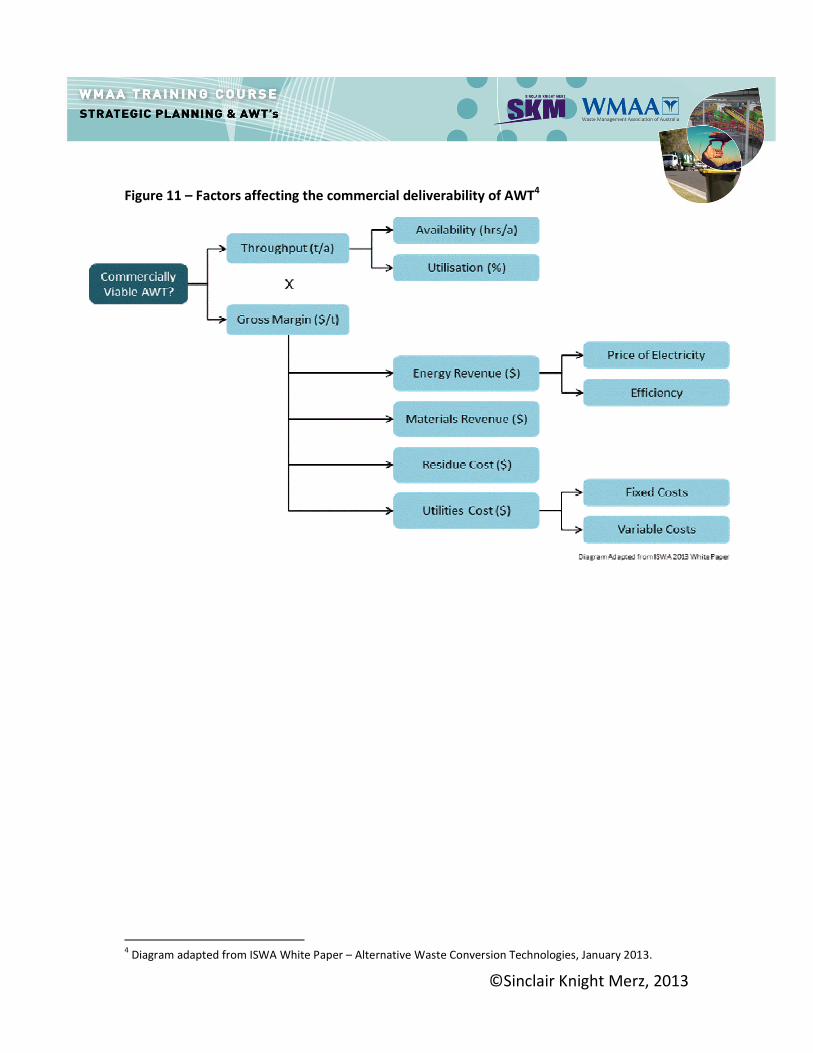
Figure 11 shows a range of factors which affect the commercial deliverability of an AWT
solution. Whilst a technology may physically operate with limited technical operational issues
in one location and achieve a “positive” outcome, this doesn't not necessarily mean that the
same technology and configuration will achieve a “positive” outcome in another geographical
locality, although it may technically “work”. This is particularly pertinent in Australia where
examples of technically and commercially successful AWTs from overseas are provided as
evidence that an AWT will be successful here.
When considering the commercial viability of a proposed offer of a solution, it is important to
understand the detail of each of these variables and test the robustness of the assumptions
made; especially utilities cost (which includes fixed cost such as capital cost and more
importantly variable costs such as personnel, maintenances, water, gas, sewerage,
electricity and so on). If these assumptions are not accurate, the proposed solution can
quickly change from being commercially viable to not being commercially viable.
This presents a conundrum for emerging technologies. For example technologies such as
moving grate incineration have been operating for a long time in a number of countries
across the globe and can evidence a long history of performance data. Hence they provide a
reasonably accurate prediction of utility costs and energy revenue; whereas for an emerging
advanced thermal treatment technology, with limited history, this is less the case.
©Sinclair Knight Merz, 2013
Figure 11 – Factors affecting the commercial deliverability of AWT4
4 Diagram adapted from ISWA White Paper – Alternative Waste Conversion Technologies, January 2013.

©Sinclair Knight Merz, 2013
Understanding Cost and Price Information
Cost and price details can be expressed in a number of different ways. Some of these are
specific to the waste management industry and others follow more common financial
terminology. For any cost, it is important to understand the underlying assumptions and
scope or coverage. Key terminology is presented below.
Cost per tonne ($/t) A commonly quoted term is the cost per tonne, which is often used when referring to the
costs of collection and/or disposal. The term 'cost per household' is also used, particularly
with regard to waste collection.
Gate fee ($/t) Gate fee is the price paid to treat/dispose of waste at a facility, typically expressed as per
tonne. Values will vary depending on whether this is a private or public sector gate fee, local
market conditions, duration of contract etc.
The gate fee paid may or may not cover the cost of treating the waste delivered to the
facility. In some cases a gate fee may be paid which is lower than the cost of the service
provision. This may occur if the facility accepts wastes other than municipal waste. In some
cases the 'spot price' paid by one-off deposits is higher than the agreed contract price with a
local authority, which provides a guaranteed revenue stream. Alternatively subsidies may
support the operation of a facility. A gate fee may also be higher than the actual cost per
tonne of operating the facility. A gate fee may vary over time depending on local market
conditions and the availability of other facilities locally.
Total Cost The total cost can relate to both the capital and operating costs both plus the full list of costs in the 'Other Costs' section described above.
Net Present Value (NPV) Costs can be presented in 'real prices' or 'nominal rates' (i.e. which include inflation) or in
terms of 'net present value'. NPV is an accounting term used to express future costs and
benefits in present day terms to give a better understanding of relative costs. It is used
principally in comparing options when assessing the optimum solution for an investment. A
discount rate is applied which has the effect of reducing the present value in future years.
The real or nominal rate refers to an undiscounted rate in which inflation is not applied.
NPV is essentially an amount that expresses how much cost an investment or project will
result in.

©Sinclair Knight Merz, 2013
Procuring New Waste Treatment Infrastructure
The procurement of new waste treatment infrastructure is typically a complex, time-
consuming and costly exercise. Best practice in procuring waste infrastructure includes the
development of a procurement plan, which embraces the local policy drivers, constraints and
the expectations of the stakeholders. The procurement plan should allow for the continual
appraisal of the choice of technology since there may be changes that result in other
technologies becoming more attractive through time as more information becomes available.
The role of a prospective new technology in the delivery of the service will have to be the
subject of an assessment as it is likely to have to complement existing practices such as
collection and potentially any other existing treatment and disposal services.
The Procurement Plan
The procurement plan comprises consideration of a number of important criteria for the
service/infrastructure being procured. These may be summarised in this context as:
� Scope - What services are required to be delivered through the contract? Is it
technology specific or are there a variety of alternative options to deliver the service?
� Duration - What is an appropriate commencement date and cessation date for the
contract? Should there be a review period at a particular milestone date/option to
extend? What duration is realistic given the likely amount of capital investment involved?
� Partnering - Would the contract/service benefit from partnering with other local
authorities and/or other parties, e.g. community groups? This may be governed by
issues such as Best Value, efficiency reviews etc.
� Contract Type - What form of contract is appropriate for the authority/s to let? For
example, 'Operate only', or 'Design, Build and Operate’ or (more commonly) 'Design,
Build, Finance and Operate'? This is likely to be governed by available
finance/resources and infrastructure available to the authority/s.
� Funding - How is the service to be funded?
� Provision of Facilities - What, if any, facilities will be passed on for usage under the
procured service (e.g. transfer stations, vehicle depots, etc)?
� Development approval - Are sites specified in the planning documentation? Have sites
been acquired by the local authority/s? Is planning permission already granted on any
sites for relevant waste activities? Are works approvals in place?
� Staff Issues - Are existing staff to be transferred into the successful new service
providers’ employment? If so what are the required arrangements that need to be
provided by the successful contractor?
� Market Appetite - Is the contract of sufficient interest to a range of service providers? If
not, will there be enough potential bidders to make it competitive?

©Sinclair Knight Merz, 2013
� Stakeholders - What stakeholders need to be engaged? Are they engaged in the
process? Are the stakeholder issues anticipated, e.g. with regard to location/choice of
facilities?
Contract Documentation and Procedures
As an outcome of the procurement plan considerations noted above, there is a need to
develop appropriate contract documentation and establish procedures in order to commence
the formal procurement of the service. The contract documentation may be considered as
three main elements supported by a risk assessment. The three elements are the
specification, the payment mechanism and the terms and conditions.
Contract Specification
The contract specification defines the procuring organisation’s requirement for the services.
The provider must perform the services in accordance with the requirements set out in the
specification. The specification should be linked to the payment mechanism as an incentive
for the provider in delivery of the service, and as a remedy for default of services.
Generally, there are two types of specification:
� Output specifications which set out performance standards for provision of the services
i.e. what the service should achieve but not how it should be achieved; and
� Input or method specifications which set out specific requirements for provision of the
services i.e. how the service should be operated.
The procuring organisation should choose the most appropriate approach dependent upon
the local circumstances. The choice between the two essentially is concerned with balance
and transfer of control and risk between the parties. An output specification maximises risk
transfer in that it primarily defines performance standards, with the contractor providing the
approach/method. An input specification is more prescriptive, thus allowing the authority to
define how things will be done, but in so doing the authority has implicitly accepted risk if the
methodology does not deliver the desired outcome. The specification may include both
output and input based requirements for different elements of the project. Specifying input
and output requirements for the same element is not recommended. Both input and output
specifications should require service delivery plans to develop and implement the services.
©Sinclair Knight Merz, 2013
Procurement Process Timeline
Each procuring organisation (e.g. local council, regional waste management group, or
private company) will have legislation, standing orders or a constitution that governs how
services and infrastructure are to be procured.
The procurement of a reasonable size waste treatment service contract (say in the region of
75,000 to 250,000 tonnes of waste per year) can take between 22 and 36 months to
complete. This period is up to financial close and does not include design and construction
which could add 24 – 60 months. Site provision and planning permission are also very
influential on project timeframes.
©Sinclair Knight Merz, 2013
Useful Waste Strategic Planning References:
A list of references is available on the Waste Management Association of Australia (WMAA)
website using the log in details sent by WMAA to the attending delegate.