strain sensors based on bragg gratings
TRANSCRIPT

IMEKO 20th TC3, 3rd TC16 and 1st TC22 International Conference Cultivating metrological knowledge
27th to 30th November, 2007. Merida, Mexico.
Strain sensors based on bragg gratings
K. Haase
Hottinger Baldwin Messtechnik GmbH, Germany Abstract
Enormous technological progress in optical fibers for telecommunications has promoted the use of functional grids, mainly in sensor technology. To date, optical sensors with micro-structured Bragg gratings in the core of crystal fibers have been principally used in laboratories, however, there have also been first practical applications. In this paper, HBM’s own practical and theoretical investigations are presented as well as product development based on photonic Bragg sensors. The paper discusses strain and temperature related influences in conjunction with dynamically induced Bragg gratings in optical single-mode fibers and stress-induced interference on the grid.
New products from HBM such as special software modules and hardware components for signal processing of photonic sensors linking electrical and optical systems are briefly introduced at the end of the paper, as well as potential of high strain level applications will be demonstrated.
Keywords: Optical strain gage, composite material, structural durability, high strain
1. Fiber Optical Bragg Sensors for Strain Measurement
Fiber optical sensor technology for strain measurement has increasingly come
into focus over the past decade. The most frequently used technology involves inscribing nano-structured Bragg gratings in the form of periodic variations of the optical refractive index into the core of optical fibers made of glass. The Bragg grating period represents a length scaling that can be influenced by external strains. The scale length can be determined through the wavelength of the light reflected in the optical fiber, similar to the schematic as shown in Figure 1. Hence, the optical fiber functions as both a sensor element and a transmitting medium for the sensor signals.
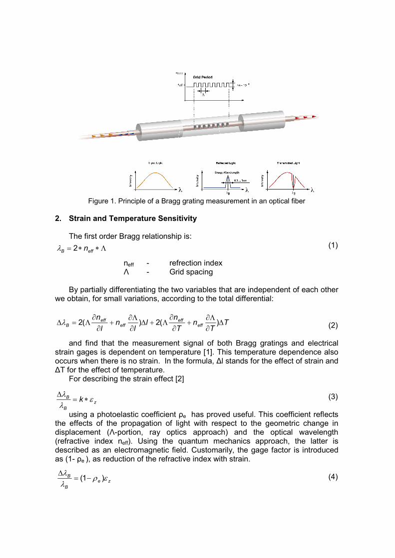
Figure 1. Principle of a Bragg grating measurement in an optical fiber
2. Strain and Temperature Sensitivity
The first order Bragg relationship is:
(1) neff - refrection index Λ - Grid spacing
By partially differentiating the two variables that are independent of each other we obtain, for small variations, according to the total differential:
(2)
and find that the measurement signal of both Bragg gratings and electrical strain gages is dependent on temperature [1]. This temperature dependence also occurs when there is no strain. In the formula, ∆l stands for the effect of strain and ∆T for the effect of temperature.
For describing the strain effect [2]
(3)
using a photoelastic coefficient ρe has proved useful. This coefficient reflects the effects of the propagation of light with respect to the geometric change in displacement (Λ-portion, ray optics approach) and the optical wavelength (refractive index neff). Using the quantum mechanics approach, the latter is described as an electromagnetic field. Customarily, the gage factor is introduced as (1- ρe ), as reduction of the refractive index with strain. (4)
Λ∗∗= effB n2λ
TT
nT
nl
ln
l
neff
effeff
effB ∆
∂
Λ∂+
∂
∂Λ+∆
∂
Λ∂+
∂
∂Λ=∆ )(2)(2λ
ze
B
B ερλ
λ)1( −=
∆
z
B
B k ελ
λ∗=
∆
According to [3] the formula for the photoelastic coefficient is found using 3D
continuum mechanics (equation 5): (5)
Using the coefficients for a germanium silicate fiber found in the references [4]
482.1;16.0;252.0;113.0 1211 ==== effnνρρ
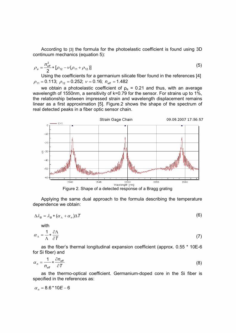
we obtain a photoelastic coefficient of ρe = 0.21 and thus, with an average wavelength of 1550nm, a sensitivity of k=0.79 for the sensor. For strains up to 1%, the relationship between impressed strain and wavelength displacement remains linear as a first approximation [5]. Figure.2 shows the shape of the spectrum of real detected peaks in a fiber optic sensor chain.
Figure 2. Shape of a detected response of a Bragg grating
Applying the same dual approach to the formula describing the temperature
dependence we obtain: (6)
with (7)
as the fiber’s thermal longitudinal expansion coefficient (approx. 0.55 * 10E-6 for Si fiber) and (8)
as the thermo-optical coefficient. Germanium-doped core in the Si fiber is specified in the references as:
)]([2
121112
2
ρρνρρ +−∗= effe
n
TnBB ∆+∗=∆ Λ )( ααλλ
T∂
Λ∂∗
Λ=Λ
1α
T
n
n
eff
eff
n∂
∂∗=
1α
610*6.8 −= Enα
In comparison to the thermally induced longitudinal expansion of 0.55 * 10E-6,
the thermo-optical effect is prevailing with the Si fiber [6]. The temperature sensitivity of the waveguide, with an average wavelength of
1550nm in a temperature range from ambient temperature up to 100°C, is approximately +10.6 pm/K.
Consequently, particular effort and attention should be paid to compensating temperature effects. 3. Various Aspects of Application
HBM has completed its proven range of products and services for the
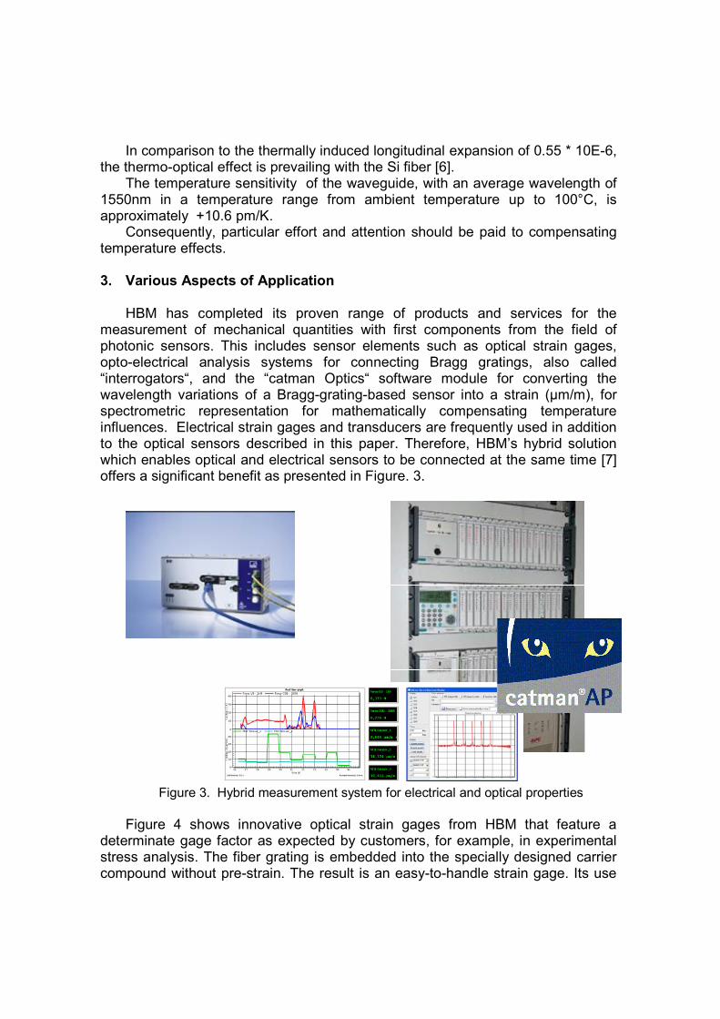
measurement of mechanical quantities with first components from the field of photonic sensors. This includes sensor elements such as optical strain gages, opto-electrical analysis systems for connecting Bragg gratings, also called “interrogators“, and the “catman Optics“ software module for converting the wavelength variations of a Bragg-grating-based sensor into a strain (µm/m), for spectrometric representation for mathematically compensating temperature influences. Electrical strain gages and transducers are frequently used in addition to the optical sensors described in this paper. Therefore, HBM’s hybrid solution which enables optical and electrical sensors to be connected at the same time [7] offers a significant benefit as presented in Figure. 3.
Figure 3. Hybrid measurement system for electrical and optical properties
Figure 4 shows innovative optical strain gages from HBM that feature a
determinate gage factor as expected by customers, for example, in experimental stress analysis. The fiber grating is embedded into the specially designed carrier compound without pre-strain. The result is an easy-to-handle strain gage. Its use

is similar to the use of customary strain gages available on the market for decades.
Bragg-grating-based optical sensors prove especially useful to customers, wherever conventional measurement equipment meets its limits, for example, in harsh environments such as
� Environments with electromagnetic interference � Fields with high energetic potential (e.g. high voltage).
Optical strain gages offer additional benefits over conventional, electrical
strain gages, because of the small mass of the connection leads and the reduced wiring effort resulting from the multiplexibility of the measuring points.
Figure 4. Optical strain gages
4. Application Example: Measurement on Composite Materials
Finally, the achievement potential of fiber-optical strain gage technology is to be presented more in detail by considering the material behavior of composite materials. These composite materials combine the favorable properties of the components involved, mostly (e.g. polymer) matrix and glass or carbon fibers for high stresses. As a result of the increasing demand for high-performance structures providing low density and improved strength properties, there has been enormous technological progress in the manufacture of such components. In
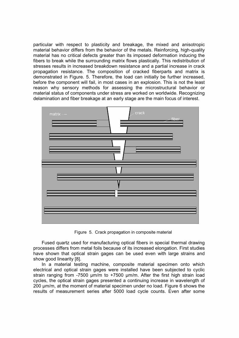
particular with respect to plasticity and breakage, the mixed and anisotropic material behavior differs from the behavior of the metals. Reinforcing, high-quality material has no critical defects greater than its imposed deformation inducing the fibers to break while the surrounding matrix flows plastically. This redistribution of stresses results in increased breakdown resistance and a partial increase in crack propagation resistance. The composition of cracked fiberparts and matrix is demonstrated in Figure. 5. Therefore, the load can initially be further increased, before the component will fail, in most cases in an explosion. This is not the least reason why sensory methods for assessing the microstructural behavior or material status of components under stress are worked on worldwide. Recognizing delamination and fiber breakage at an early stage are the main focus of interest.
Figure 5. Crack propagation in composite material
Fused quartz used for manufacturing optical fibers in special thermal drawing
processes differs from metal foils because of its increased elongation. First studies have shown that optical strain gages can be used even with large strains and show good linearity [8].
In a material testing machine, composite material specimen onto which electrical and optical strain gages were installed have been subjected to cyclic strain ranging from -7500 µm/m to +7500 µm/m. After the first high strain load cycles, the optical strain gages presented a continuing increase in wavelength of 200 µm/m, at the moment of material specimen under no load. Figure 6 shows the results of measurement series after 5000 load cycle counts. Even after some
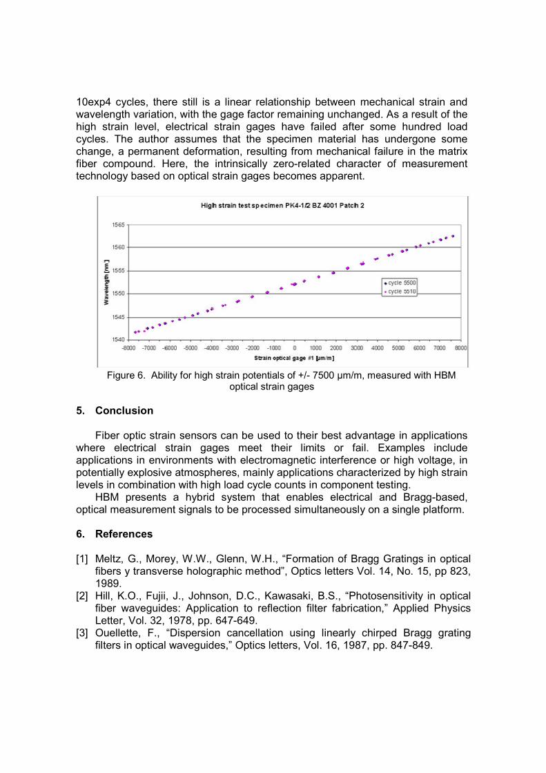
10exp4 cycles, there still is a linear relationship between mechanical strain and wavelength variation, with the gage factor remaining unchanged. As a result of the high strain level, electrical strain gages have failed after some hundred load cycles. The author assumes that the specimen material has undergone some change, a permanent deformation, resulting from mechanical failure in the matrix fiber compound. Here, the intrinsically zero-related character of measurement technology based on optical strain gages becomes apparent.
Figure 6. Ability for high strain potentials of +/- 7500 µm/m, measured with HBM
optical strain gages
5. Conclusion
Fiber optic strain sensors can be used to their best advantage in applications
where electrical strain gages meet their limits or fail. Examples include applications in environments with electromagnetic interference or high voltage, in potentially explosive atmospheres, mainly applications characterized by high strain levels in combination with high load cycle counts in component testing.
HBM presents a hybrid system that enables electrical and Bragg-based, optical measurement signals to be processed simultaneously on a single platform. 6. References [1] Meltz, G., Morey, W.W., Glenn, W.H., “Formation of Bragg Gratings in optical
fibers y transverse holographic method”, Optics letters Vol. 14, No. 15, pp 823, 1989.
[2] Hill, K.O., Fujii, J., Johnson, D.C., Kawasaki, B.S., “Photosensitivity in optical fiber waveguides: Application to reflection filter fabrication,” Applied Physics Letter, Vol. 32, 1978, pp. 647-649.
[3] Ouellette, F., “Dispersion cancellation using linearly chirped Bragg grating filters in optical waveguides,” Optics letters, Vol. 16, 1987, pp. 847-849.

[4] Bertholds, A., Dändliker, R., “Determination of the individual strain optic coefficients in single mode optical fibers”, Journal of lightwave technology, Vol. 6, No.1, pp. 17 -20, 1988.
[5] Trutzel, M., „Dehnungsermittlung mit faseroptischen Bragg-Gitter-Sensoren“, Berlin 2001, D83; Dissertation
[6] Shibata, S., Shibata, T., Edahiro, T., “Refractive Index dispersion of lightguide glasses at high temperature” Electronics letters, Vol. 17, No. 8, pp. 310-311, 1981.
[7] Kreuzer, M., “Strain Measurement with Fiber Bragg Grating Sensors”, http://www.hbm.com
[8] Roths, J., “Test and Measurement / Composites at high strain levels”, Internal report. FB06 Feinwerk- und Mikrotechnik, Physikalische Technik. Fachhochschule München.