stq cc0 regen speed kit - buggiesunlimited.com car/speed kit...stq cc0 regen speed kit ... main wire...
TRANSCRIPT

STQ CC0 REGEN SPEED KITConversion Instructions for 48-volt Club Car 1998 ~ 2001 DS Models with Regen II System
Buggies Unlimited888-444-9994
buggiesunlimited.com
© Copyright 1997-2008 Buggies Unlimited. All Rights Reserved.
1
Speed Kit Conversion Instructions
Thank you for purchasing our exclusive STQ CC0 REGEN Speed Kit. We take great pride in our products and feel certain that this kit will offer you many years of trouble-free service. We ask that you take a moment to read these instructions completely before beginning your installation. Familiarity with the parts and an understanding of the procedures will ensure that your installation goes smoothly and safely. Additionally, it will give you an opportunity to determine if your cart might have any damaged, corroded, or missing parts which will need replacing prior to using your new speed kit.
About This Speed Kit
This speed kit is designed specifically for Club Car 48 volt REGEN II electric golf carts. If you are unsure of your golf cart type, please see our catalog or contact our technical department, toll free a 1-888-444-9994,or online at www.buggiesunlimited.com. During the installation of this kit you will be upgrading four major electrical components from your golf cart, with four high performance components in our STQ CC0 REGEN Speed Kit. These parts are: the motor, the speed controller, the solenoid, and the forward reverse assembly. Allof your electrical connections will be made between these components and the battery group. You should allow about 4 hours for installation. As you complete each step, it is recommended to check it off as completed. Thisway if you are unable to complete this installation all at one time, you will know exactly where you left off.
Parts Included In Our Kit
1) High Performance electric motor (per application). 2) 727 amp speed controller.3) Main solenoid (48 V).4) 4 gauge Club Car cable kit including:
a) 1 red coded cable.b) 2 blue coded cables.c) 1 white coded cable.d) 1 orange coded cable. e) 1 green coded cable. f) 1 black coded cable. g) 1 yellow coded cable. h) 5 red/black coded cables.
5) Forward & reverse switch assembly.6) Jumper buss bar.7) Pre-charge resistor.
8) Wire harness kit9) Hardware kit.10) F&R Switch Handle (not shown)11) Screw12) Bracket
C/2S 107

Tools And Materials Required To Install Kit
1) SAE socket set, with ratchet and 3” and 6” extensions.2) SAE combination wrench set. 3) #2 Phillips and Flat Tip screwdrivers. 4) Wire cutters.5) Wire crimpers.6) Heavy weight grease.7) Safety goggles/glasses.8) Lifting Jack & Jack-stands9) Torque Wrench (in/lb & ft/lb)10) Drill (not shown)11) 7/32” Drill Bit (not shown)
Additional Tools Which Make The Job Better And Faster
1) Battery Carrying Strap. Part #BT8001. 2) Battery Terminal Protector Spray. Part # BT60512. 3) Battery Terminal Re-Facer. Part # BU6002. 4) Electronic Multi-meter. Part # BU6001. 5) Small Box of Baking Soda. (Local store purchase)
6) Quality Anti-Sieze Compound or Wheel Bearing Grease. (Local store purchase)
A Note Before Starting
Throughout this conversion, we will be discussing the connection of #4 heavy gauge cables to several different electrical components. Some cables will be attached to threaded terminals or “posts” as found on motors and others will be attached to fl at bus bars. An understanding of each of these cable connections is important. Let’s fi rst cover the threaded terminals. You will notice these terminals utilize a set of double nuts to hold the cable terminal fi rmly in place. Typically, a cable terminal and a washer will be sandwiched between these two nuts. An open-end wrench of the appropriate size should be used to hold the top nut, while using another wrench to hold the bottom nut. This eliminates the possibility of damaging the terminals or internal parts of the motor. (See fi g 5) Failure to use the double wrench technique on double-nutted terminals can permanently damage the motor. You will also want to use the double wrench technique when making connections at the fl at bus bars of the controller, but care should also be given to avoid twisting or bending the bars. Again, the seals at the base of the controller bus bars are fragile and subject to damage, if handled improperly. Seal damage or bent bus bars will void the warranty for that component.
2
BT8001 BT60512 BU6002 BU6001

Conversion Process
CAUTION: During this installation it is necessary that you wear eye protection at all times. A lifting jack and appropriately rated jack stands must be used to lift and safely support the cart.
1) Seat Removal: Grasp the seat handles and rotate the seat forward and lift the seat from the hinges.
2) Access Panel Removal: Remove the black plastic rear access panel that is located between and behind the front seats using a #2 Phillips screwdriver. It will be easier to get at the necessary connections, if you remove the sweater basket or any other seats or cargo boxes on the rear of the cart. You can also access the components from under the cart if needed.
3) Battery Disconnect: Make sure you have the correct eye protection before continuing. Be sure the tow switch is in the tow position, then remove the battery cable connections at battery #1 and #6. See figure 3. Remove all short battery cables from each battery at this point. It will not be necessary to remove the batteries to install this kit. It is recommended to clean the batteries using a mixture of 1 cup of baking soda and 1 gallon of water.For best results, re-face the battery terminal connections to achieve optimal electrical flow (see additional tools above). Rinse completely then allow time to dry before continuing with component removal.
4) Controller and Solenoid Removal: First remove the controller cover, then disconnect all of the cables and main wire harness connections from the controller.Be sure to depress the lock tabs before attempting to remove the wire harness plugs from the controller. Now remove the four controller mounting bolts and remove the controller from the cart. The four mounting bolts willbe re-used, so set them aside for now. Next, remove the two mounting bolts that hold the solenoid to the frame. Keep these two bolts since they too will be used later.Now, unplug the main wire harness from the onboard computer.
6) Motor Removal: Using the lifting jack, lift the cart high enough for you to comfortably work under the cart.
CAUTION: Make sure to use a lifting jack to lift the cart and use appropriately rated jack stands to safely support the cart before proceeding!
1. Seat Removal
2. Access Panel Removal
3. Battery Disconnect
3
Access Panel
12
3
4
56
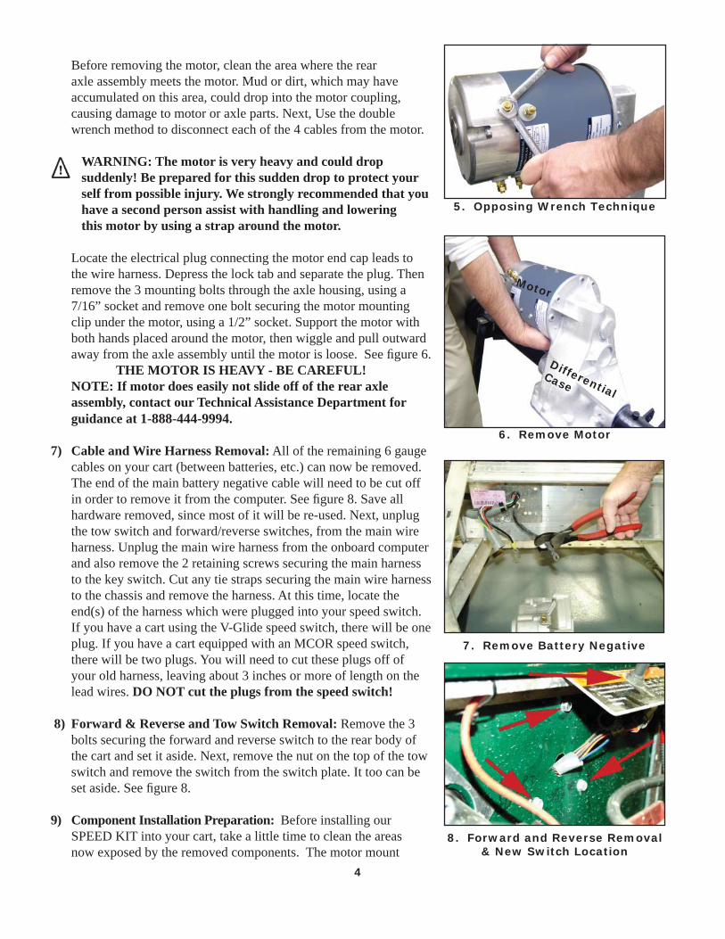
Before removing the motor, clean the area where the rear axle assembly meets the motor. Mud or dirt, which may have accumulated on this area, could drop into the motor coupling, causing damage to motor or axle parts. Next, Use the double wrench method to disconnect each of the 4 cables from the motor.
WARNING: The motor is very heavy and could dropsuddenly! Be prepared for this sudden drop to protect your self from possible injury. We strongly recommended that you have a second person assist with handling and lowering this motor by using a strap around the motor.
Locate the electrical plug connecting the motor end cap leads to the wire harness. Depress the lock tab and separate the plug. Thenremove the 3 mounting bolts through the axle housing, using a 7/16” socket and remove one bolt securing the motor mounting clip under the motor, using a 1/2” socket. Support the motor with both hands placed around the motor, then wiggle and pull outward away from the axle assembly until the motor is loose. See figure 6.
THE MOTOR IS HEAVY - BE CAREFUL!NOTE: If motor does easily not slide off of the rear axle assembly, contact our Technical Assistance Department forguidance at 1-888-444-9994.
7) Cable and Wire Harness Removal: All of the remaining 6 gauge cables on your cart (between batteries, etc.) can now be removed. The end of the main battery negative cable will need to be cut offin order to remove it from the computer. See figure 8. Save all hardware removed, since most of it will be re-used. Next, unplug the tow switch and forward/reverse switches, from the main wire harness. Unplug the main wire harness from the onboard computer and also remove the 2 retaining screws securing the main harness to the key switch. Cut any tie straps securing the main wire harness to the chassis and remove the harness. At this time, locate the end(s) of the harness which were plugged into your speed switch. If you have a cart using the V-Glide speed switch, there will be one plug. If you have a cart equipped with an MCOR speed switch, there will be two plugs. You will need to cut these plugs off of your old harness, leaving about 3 inches or more of length on the lead wires. DO NOT cut the plugs from the speed switch!
8) Forward & Reverse and Tow Switch Removal: Remove the 3 bolts securing the forward and reverse switch to the rear body of the cart and set it aside. Next, remove the nut on the top of the tow switch and remove the switch from the switch plate. It too can be set aside. See figure 8.
9) Component Installation Preparation: Before installing our SPEED KIT into your cart, take a little time to clean the areas now exposed by the removed components. The motor mount
4
6. Remove Motor
Motor
DifferentialCase
5. Opposing Wrench Technique
8. Forward and Reverse Removal& New Switch Location
7. Remove Battery Negative

may have some grit or dirt around the opening of the mount.A moist rag or small brush can be used to clean that area. Avoid letting dirt fall into the housing. Be sure to check the mounting surface of the controller to be sure it is completelyclean. Wipe it down with a damp cloth to remove dirt or fi lm. This area acts as a heat sink and dirt will interfere with the controller’s performance.
10) Motor Installation: Before mounting the motor, lubricate the splines but not the
end of the motor shaft with anti-sieze compound or a quality heavy-weight grease available from any auto parts store. Lift the new motor up into place and slide it onto the shaft of the axle assembly. With some gentle side to side movement and pressure toward the housing, the motor should slide up tight to the housing with little effort. DO NOT USE THE MOUNTING BOLTS TO DRAW THE MOTOR ONTO THE REAR AXLE ASSEMBLY INPUT SHAFT. If it does not slide into place easily, remove the motor and inspect for dirt or debris which might prevent the motor from sliding onto the shaft. Rotate the motor so that 2 terminals are high in front of the motor and 2 are low in front. See fi gure 9. Align the mounting holes of the motor to the mounting holes of the housing and insert the three mounting bolts. Tighten these three bolts using a criss-cross tightening pattern, to ensure that the motor is not binding or stressed. Tighten to 5 ~ 6 ft. lb. Now install the lower clip to support the motor. Torque to 6 ~ 7 ft. lb. See fi gure 10.
11) Forward/Reverse Assembly Installation: Place the forward/reverse switch assembly INSIDE of the rear
body (under the empty tow switch plate), at the same mounting location as the original forward/reverse switch and mount box.Attach the assembly to the mounting area on the cart using the hardware supplied in the kit. Finally, secure the shift lever to the switch shaft (outside of the body) using the screw included with the switch. Refer to pictures 8.
12) Controller and Solenoid Installation:Position the controller against the open area in the middle of the frame panel (staying close to the onboard computer) and mark the 4 holes as shown in fi gure 11. DO NOT mount the controller too far to the right or there will not be suffi cient clearance between the controller and the solenoid. Make sure you have the controller terminals to the right (passenger) side of the cart. Now drill the holes you have marked using a 7/32” drill bit. Install the controller using the original “thread forming” bolts used to mount the original controller. These bolts will thread the holes as they are installed, without requiring any special preparation. Using the original hardware from the main solenoid, install the new solenoid to the right of the controller. Use the two holes already in the frame. See fi gure 12. Install the solenoid with the
5
9. Motor Top View
10. Install Motor Clip
11. Controller Installation
12. Solenoid Mounting
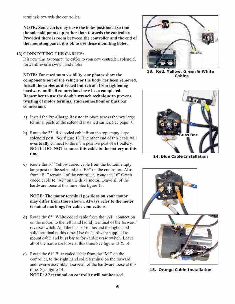
terminals towards the controller.
NOTE: Some carts may have the holes positioned so that the solenoid points up rather than towards the controller. Provided there is room between the controller and the end of the mounting panel, it is ok to use these mounting holes.
13) CONNECTING THE CABLES: It is now time to connect the cables to your new controller, solenoid,
forward/reverse switch and motor.
NOTE: For maximum visibility, our photos show the components out of the vehicle or the body has been removed. Install the cables as directed but refrain from tightening hardware until all connections have been completed. Remember to use the double wrench technique to prevent twisting of motor terminal stud connections or buss bar connections.
a) Install the Pre-Charge Resistor in place across the two large terminal posts of the solenoid installed earlier. See page 10.
b) Route the 23” Red coded cable from the top empty large solenoid post. See fi gure 13. The other end of this cable will eventually connect to the main positive post of #1 battery. NOTE: DO NOT connect this cable to the battery at this time!
c) Route the 16” Yellow coded cable from the bottom empty large post on the solenoid, to “B+” on the controller. Also from “B+” terminal of the controller, route the 16” Green coded cable to “A2” on the drive motor. Leave all of the hardware loose at this time. See fi gure 13.
NOTE: The motor terminal positions on your motor may differ from those shown. Always refer to the motor terminal markings for cable connections.
d) Route the 65” White coded cable from the “A1” connection on the motor, to the left hand (solid) terminal of the forward/reverse switch. Add the bus bar to this and the right hand solid terminal at this time. Use the hardware supplied to mount cable and buss bar to forward/reverse switch. Leave all of the hardware loose at this time. See fi gure 13 & 14.
e) Route the 61” Blue coded cable from the “M-” on the controller, to the right hand solid terminal on the forward and reverse assembly. Leave all of the hardware loose at this time. See fi gure 14. NOTE: A2 terminal on controller will not be used.
66
13. Red, Yellow, Green & White Cables
Buss Bar
14. Blue Cable Installation
15. Orange Cable Installation
7
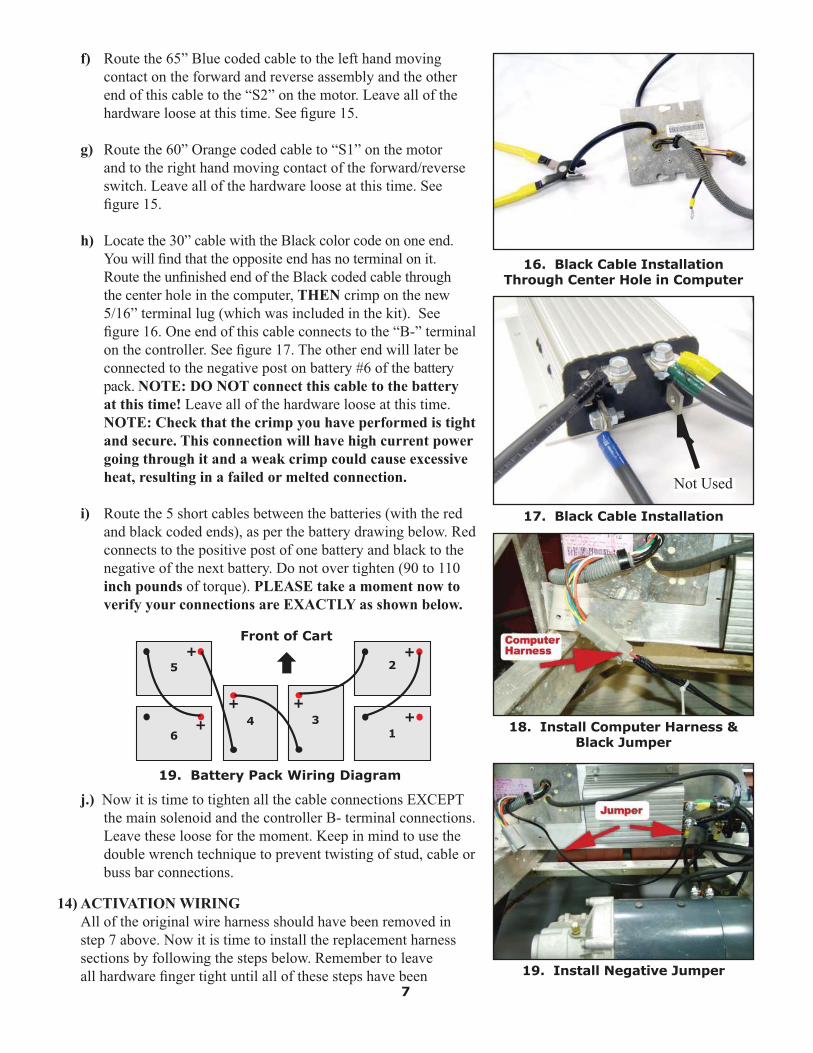
f) Route the 65” Blue coded cable to the left hand moving contact on the forward and reverse assembly and the other end of this cable to the “S2” on the motor. Leave all of the hardware loose at this time. See fi gure 15.
g) Route the 60” Orange coded cable to “S1” on the motor and to the right hand moving contact of the forward/reverse switch. Leave all of the hardware loose at this time. See fi gure 15.
h) Locate the 30” cable with the Black color code on one end. You will fi nd that the opposite end has no terminal on it. Route the unfi nished end of the Black coded cable through the center hole in the computer, THEN crimp on the new 5/16” terminal lug (which was included in the kit). See fi gure 16. One end of this cable connects to the “B-” terminal on the controller. See fi gure 17. The other end will later be connected to the negative post on battery #6 of the battery pack. NOTE: DO NOT connect this cable to the battery at this time! Leave all of the hardware loose at this time. NOTE: Check that the crimp you have performed is tight and secure. This connection will have high current power going through it and a weak crimp could cause excessive heat, resulting in a failed or melted connection.
i) Route the 5 short cables between the batteries (with the red and black coded ends), as per the battery drawing below. Red connects to the positive post of one battery and black to the negative of the next battery. Do not over tighten (90 to 110 inch pounds of torque). PLEASE take a moment now to verify your connections are EXACTLY as shown below.
19. Battery Pack Wiring Diagram
Front of Cart
1
2
6
5
34
+
+
++
+
+
j.) Now it is time to tighten all the cable connections EXCEPT the main solenoid and the controller B- terminal connections. Leave these loose for the moment. Keep in mind to use the double wrench technique to prevent twisting of stud, cable or buss bar connections.
14) ACTIVATION WIRING All of the original wire harness should have been removed in step 7 above. Now it is time to install the replacement harness sections by following the steps below. Remember to leave all hardware fi nger tight until all of these steps have been
17. Black Cable Installation
16. Black Cable Installation Through Center Hole in Computer
Not Used
18. Install Computer Harness & Black Jumper
19. Install Negative Jumper

8
completed.
a) Locate the short computer harness with the red wire going into the 6 pin gray plug. Connect the plug end to the carts computer. Place the eye terminal of the red lead onto the main solenoid #1 top terminal, along with the main battery positive (+) cable. See page 11.
b) Locate the short 15” black 10 gauge lead coming out of the On Board Computer, with an eye terminal on one end. The loose end with the eye terminal must be installed onto the negative “B-” terminal of the controller. See page 11. On some carts, this lead may be too short to reach the controller. If this is the case, cut the end from your black 10 gauge lead coming out of the On Board Computer and add the black 10 gauge extension included in this kit.
c) Locate the 67” wire harness with two black wires. At one end, the two small tab connectors will be connected to the micro switch on the forward/reverse switch assembly. See fi gure 20. Then, route the wires along the right (passenger side) frame I beam and under the frame support (behind the right side batteries). See fi gure 21. One lead will be added to the “B-” terminal of the computer. The other black lead will be installed onto the main solenoid small #3 terminal towards the front of the cart. See page 11.
d) Next, you will need to add the 94” Key Switch Wire Harness (two leads - one green and one blue). The end with two small eye terminal connectors will connect to the key switch as shown on page 11 or 12. Route the harness under the front of the cart and down the right (passenger side) of the main frame I beam, along the same routing as the 67” harness to the controller area. Connect the blue lead (with the fuse holder) to the top large terminal #1 of the main solenoid. See page 11 or 12.
e) The last remaining 54” harness will complete the system. Connect the leads as follows:
1.) Yellow lead to #3 tab terminal on controller. 2.) White lead to #2 tab terminal on speed controller. 3.) Purple lead to B- terminal on speed controller. 4.) Blue (Flat terminal end) to the #1 tab terminal of the speed controller and the fi nal blue lead (Flat terminal end) to the main solenoid small terminal #4. See page 11.
The other end of this harness will be routed along the frame to the speed switch. If you have the V-Glide speed switch, route the harness up the left (driver) side of the frame. See page 11. If you have the MCOR speed switch, route the harness up the right (passenger) side of the frame. See page 12.Early on in step 7 (page 4), the plug(s) that connect to your
20. Install Micro Switch Harness
21. Harness Routing
22. Positive Battery Connection
23. Negative Battery Connection

speed switch were cut from the original harness. The forward end of this harness is terminated with 5 butt connectors, so that you can connect the original plug(s) to this new harness. Be sure to connect each color to its matching color. See page 11 if you have a V-Glide speed switch and refer to page 12 if you have an MCOR speed switch. After connecting the original harness end to your new wire harness, be sure to tape the butt connectors to assure dirt and moisture will stay out of these connections.
f.) Torque all of the hardware which has been left fi nger tight up to this point. This includes the controller, solenoid and computer negative terminals. Use care when tightening these terminals. Controller terminals should be tightened using the double wrench method. Solenoid terminals should be tightened with care since the larger terminals are soft and will strip or break off easily. Also, make sure that any cables or wiring on one terminal do not touch the cables or wiring positioned on another adjacent terminal.
NOTE: When tightening the large solenoid post nuts be sure the nut lock washer totally compresses and no movement is found in the connections. These copper posts are soft and will break off if too much torque is applied. Check to make sure that cable or wiring on one terminal are not touching cable or wiring positioned on another adjacent terminal.
15) FINAL BATTERY CABLE CONNECTIONS At this time check and recheck all wiring and cable connections for proper torque and routing. If all is in good order, it is time to make the fi nal battery connections.
a) Connect the 23” Red coded cable to #1 battery positive post. Make sure the red 12 gauge charging cable is connected as well. Torque to 90 to 110 inch pounds. See fi gure 22.
b) Connect the 30” Black coded cable to the negative post of #6 battery. See fi gure 23. You may notice some light arcing at the point of contact. This is normal and merely indicates the pre-charge of the capacitors in the controller. NOTE: A very heavy or severe arc is an indication of wiring problems and the wiring will need to be rechecked. Torque to 90 to 110 inch pounds.
c) After the fi nal connection is made (cart still supported on jack stands) place the car in the forward position and with the key switch on, push slowly on the accelerator. The cart should now run in the slow mode and as you accelerate the speed should gradually increase to full speed. Stop the wheels by applying the brakes and test run in the reverse mode. If all tests well, let the cart back down on the ground and test drive the cart. Install all removed accessories such as rear seats and inspection covers. Make sure all cables are tie strapped to solid areas as not to rub or bind on any moving parts.
NOTE: NEVER reverse direction without coming to a complete stop.
9
INDEMNIFICATION AND INSURANCE AGREEMENTHigh speed motor installation should be performed by a professional. The high speed motor purchaser assumes sole and entire responsibility for, and shall indemnify and save harmless Mattison Avenue Corporation (d.b.a. Buggies Unlimited), from any and all claim, liability, responsibility, and damage, or any costs or expenses resulting from any loss of life or injuries or claimed injuries to persons or property that may be sustained in connection with the use of any product before or after purchase, including but notlimited to high speed motors. The high speed motor purchaser also shall indemnify Mattison Avenue Corporation (d.b.a. Buggies Unlimited) and save Mattison Avenue Corporation (d.b.a. Buggies Unlimited) harmless with respect to any and all liability that maybe incurred.Golf carts are recommended for use only by those aged 16 and older. Golf carts can be especially hazardous to operate. Alwaysremember that riding and alcohol/drugs don’t mix. Never ride on public roads. Never carry more than two passengers (except shuttles and trams). Never engage in stunt driving. Avoid excessive speeds and be particularly careful on diffi cult terrain. Buggies Unlimited reserves the right, at any time, to discontinue or change specifi cations, prices, designs, features, models or equipment without notice and without incurring any obligation.
10
Buggies Unlimited888-444-9994
buggiesunlimited.com
© Copyright 1997-2008 Buggies Unlimited. All Rights Reserved.
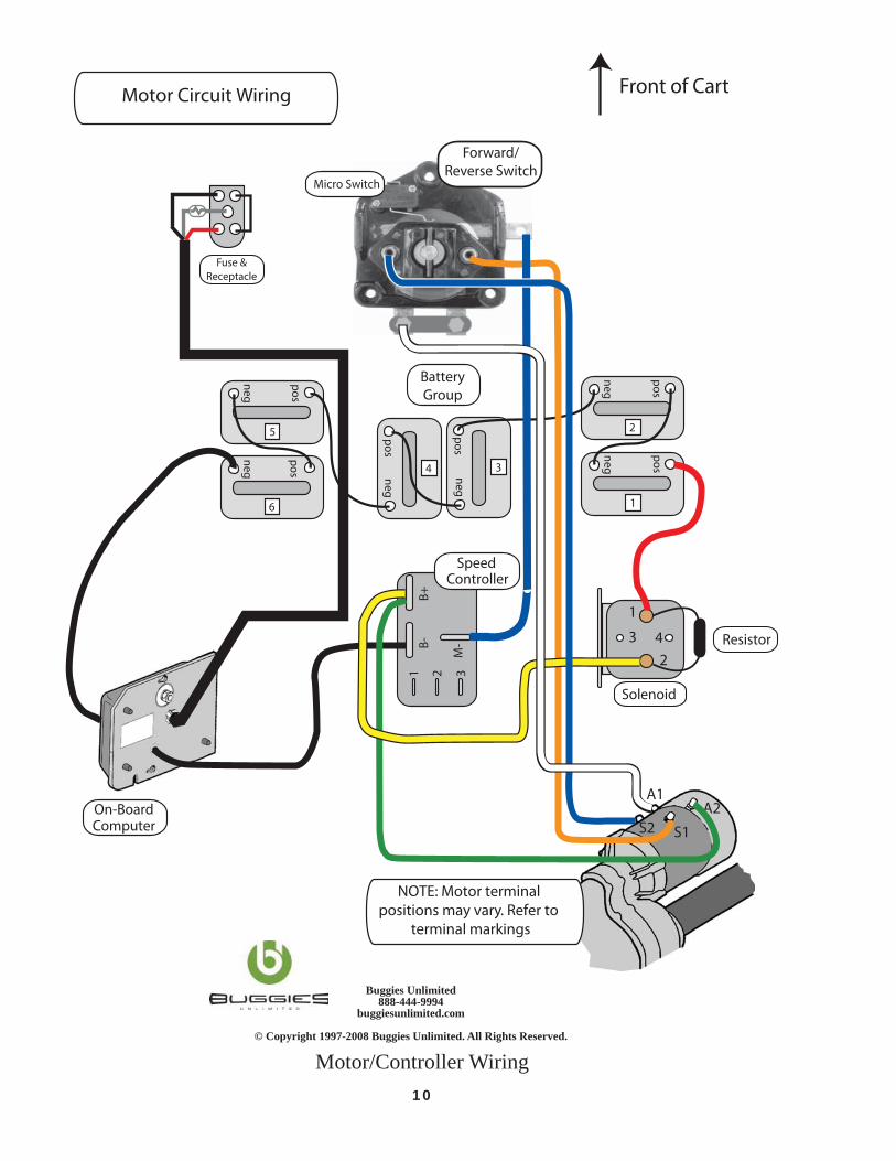
Motor/Controller Wiring
neg
pos
neg
pos
5
6
neg
pos
neg
pos
2
1
B-B+
M-
1 2 3
neg
pos
neg
pos
4 3
1
2
3 4
A2A1
S1S2
Resistor
Forward/Reverse Switch
SpeedController
Solenoid
BatteryGroup
On-BoardComputer
Fuse & Receptacle
Front of Cart
Micro Switch
Motor Circuit Wiring
NOTE: Motor terminal positions may vary. Refer to
terminal markings
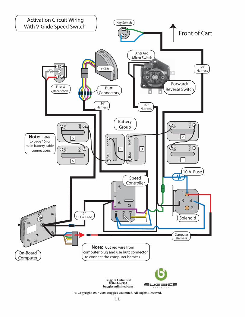
Activation Circuit WiringWith V-Glide Speed Switch
neg
pos
neg
pos
5
6
neg
pos
neg
pos
2
1
B-B+
M-
1 2 3
neg
pos
neg
pos
4 3
1
2
3 4
12
SpeedController
Solenoid
10 A. Fuse
BatteryGroup
On-BoardComputer
Fuse & Receptacle
Front of Cart
Key Switch
67”Harness
94”Harness
54”Harness
ComputerHarness
15”10 Ga. Lead
Note: Cut red wire fromcomputer plug and use butt connectorto connect the computer harness
ButtConnectors
Forward/Reverse Switch
Anti ArcMicro Switch
V-Glide
Note: Referto page 10 for
main battery cable connections
Buggies Unlimited888-444-9994
buggiesunlimited.com
© Copyright 1997-2008 Buggies Unlimited. All Rights Reserved.
11

12
Buggies Unlimited888-444-9994
buggiesunlimited.com
© Copyright 1997-2008 Buggies Unlimited. All Rights Reserved.
Activation Circuit WiringWith MCOR Speed Switch
neg
po
s
neg
po
s
5
6
neg
po
s
neg
po
s
2
1
B-
B+
M-
1 2 3
neg
po
s
neg
po
s
4 3
1
2
3 4
12
Forward/Reverse Switch
Anti Arc Micro Switch
Note: Cut red wire fromcomputer plug and use butt connectorto connect the computer harness
SpeedController
Solenoid
10 A. Fuse
BatteryGroup
On-BoardComputer
Fuse & Receptacle
Front of Cart
Key Switch
MCOR Motor Control Output Regulator
67”Harness
94”Harness
15”10 Ga. Lead
54”Harness
ComputerHarness
Note: Referto page 10 for
main battery cable connections

14
Buggies Unlimited888-444-9994
buggiesunlimited.com
© Copyright 1997 - 2008 Buggies Unlimited. All Rights Reserved.
INDEMNIFICATION AND INSURANCE AGREEMENT
High speed motor installation should be performed by a professional. The high speed motor purchas-er assumes sole and entire responsibility for, and shall indemnify and save harmless Mattison AvenueCorporation (d.b.a. Buggies Unlimited), from any and all claim, liability, responsibility, and damage, or any costs or expenses resulting from any loss of life or injuries or claimed injuries to persons or property that may be sustained in connection with the use of any product before or after purchase, including but not limited to high speed motors. The high speed motor purchaser also shall indemnify Mattison Avenue Corporation (d.b.a. Buggies Unlimited) and save Mattison Avenue Corporation (d.b.a. Buggies Unlimited) harmless with respect to any and all liability that may be incurred.
Golf carts are recommended for use only by those aged 16 and older. Golf carts can be especially hazardous to operate. Always remember that riding and alcohol/drugs don’t mix. Never ride on pub-lic roads. Never carry more than two passengers (except shuttles and trams). Never engage in stunt driving. Avoid excessive speeds and be particularly careful on difficult terrain. Buggies Unlimited reserves the right, at any time, to discontinue or change specifications, prices, designs, features, mod-els or equipment without notice and without incurring any obligation.