stormwater management plan - auckland council
TRANSCRIPT

[Type here] [Type here] [Type here]
Stormwater Management Plan Anzac Road, Pukekohe
Client Name: Askew Partnership Ltd
Job Number: 17158
Issue Date: 29th June 2020
Revision: B
1
TRIPP ANDREWS SURVEYORS LTD
DOCUMENT CONTROL RECORD Client PW, SM and GM Askew Partnership
Job Number 17158
Project Proposed Plan Change
Document Stormwater Management Report
Version B
Date 26th June 2020
Status Initial Issue
Author Jack MacDonald [email protected]
Director | Civil Engineer 021 0851 8679
Reviewed Chris Walsh
Director | Principal Planning Consultant
Approved Ann-Maree Gladding
Director | Licensed Cadastral Surveyor
Revision History
Version Date Status Author Reviewed Approved
A 8/05/2020 PPC Issue JM CW AG
B 26/06/20 RFI Updates JM CW AG
2
TRIPP ANDREWS SURVEYORS LTD
Contents:
Introduction and Background: ................................................................................................................ 5
1 Existing Site Appraisal: ........................................................................................................................ 6
1.1 Summary of Data Sources and Dates ...................................................................................... 7
1.2 Location and General Information .......................................................................................... 7
1.3 Topography ............................................................................................................................. 8
1.4 Geotechnical ........................................................................................................................... 8
1.4.1 Geotechnical Effects on Earthworks and Infrastructure ........................................................ 8
1.4.2 Soakage and Further Geotechnical Requirements ................................................................ 9
1.5 Existing Drainage Features and Stormwater Infrastructure ................................................... 9
1.5.1 Catchments ............................................................................................................................ 9
1.5.2 Existing Catchment Analysis: ............................................................................................... 11
1.5.3 Stormwater Model Setup ..................................................................................................... 12
1.6 Receiving Environment ......................................................................................................... 13
1.7 Existing Hydrological Features .............................................................................................. 13
1.8 Flooding and Flow Paths ....................................................................................................... 14
1.9 Coastal Inundation ................................................................................................................ 14
1.10 Biodiversity ........................................................................................................................... 14
1.11 Cultural and Heritage Sites ................................................................................................... 14
1.12 Contaminated Land ............................................................................................................... 14
2 Development Summary and Planning Context ............................................................................. 15
2.1 Regulatory and Design Requirements .................................................................................. 15
3 Mana Whenua Matters ................................................................................................................. 15
3.1 Identification and Incorporation of Mana Whenua Values .................................................. 15
4 Stakeholder Engagement and Consultation ................................................................................. 15
5 Proposed Development ................................................................................................................ 16
5.1 Location and Area ................................................................................................................. 16
5.2 Purpose of the Development ................................................................................................ 16
5.3 Site Layout and Urban Form ................................................................................................. 17
5.4 Earthworks ............................................................................................................................ 17
6 Stormwater Management ............................................................................................................ 17
6.1 Principles of Stormwater Management ................................................................................ 17
6.1.1 Original Principles ................................................................................................................ 17
6.1.2 Updated Principles ........................................................................................................ 18

3
TRIPP ANDREWS SURVEYORS LTD
6.2 Proposed Stormwater Management .................................................................................... 19
6.2.1 General .......................................................................................................................... 19
6.2.2 Water Quality and Quantity .......................................................................................... 19
6.2.3 Stream Hydrology ......................................................................................................... 20
6.2.4 Flooding ......................................................................................................................... 21
6.2.5 Overland Flow Path and Floodplain Management ....................................................... 21
6.2.6 Development Staging .................................................................................................... 22
6.3 Hydraulic Connectivity .......................................................................................................... 22
6.4 Asset Ownership ................................................................................................................... 22
6.5 Ongoing Maintenance Requirements ................................................................................... 22
6.6 Implementation of Stormwater Network ............................................................................. 22
6.6.1 Monitoring ........................................................................................................................... 23
6.6.2 Maintenance ........................................................................................................................ 23
6.7 Dependencies ........................................................................................................................ 24
6.8 Risks ...................................................................................................................................... 24
7 Departures from Regulatory or Design Codes .............................................................................. 24
8 Conclusion and Recommendation for Future Work ..................................................................... 25
8.2 Conclusions and Recommendations ........................................ Error! Bookmark not defined.
Appendix A: ........................................................................................................................................... 26
Appendix B: ........................................................................................................................................... 27
Appendix C: ........................................................................................................................................... 28

4
TRIPP ANDREWS SURVEYORS LTD
Appendices: Appendix A:
- Engineering Drawings o 17158 – GEN001 – Site Locality Plan o 17158 – GEN023 – Current infrastructure o 17158 – SW001 – Stormwater Proposal o 17158 – SW002 – Stormwater Pipe Catchments o 17158 – Title location plan o 17158 – SW023 – Hydrological Features
Appendix B:
- Stormwater TP108 10% AEP Calculations – Catchment 1 and 2 Pre - Stormwater TP108 10% AEP Calculations – Catchment 1 and 2 Post - Stormwater TP108 50% AEP Calculations – Catchment 1 and 2 Pre - Stormwater TP108 50% AEP Calculations – Catchment 1 and 2 Post - Stormwater TP108 1% AEP Calculations – Catchment 1 and 2 Pre - Stormwater TP108 1% AEP Calculations – Catchment 1 and 2 Post - Stormwater Pipe Capacity Check – Pipe Catchment 1 - Stormwater Pipe Capacity Check – Pipe Catchment 2 - Stormwater Pipe Capacity Check – HEC Results - Wetland Treatment Area Calculations
Appendix C:
- Safety in Design Register

5
TRIPP ANDREWS SURVEYORS LTD
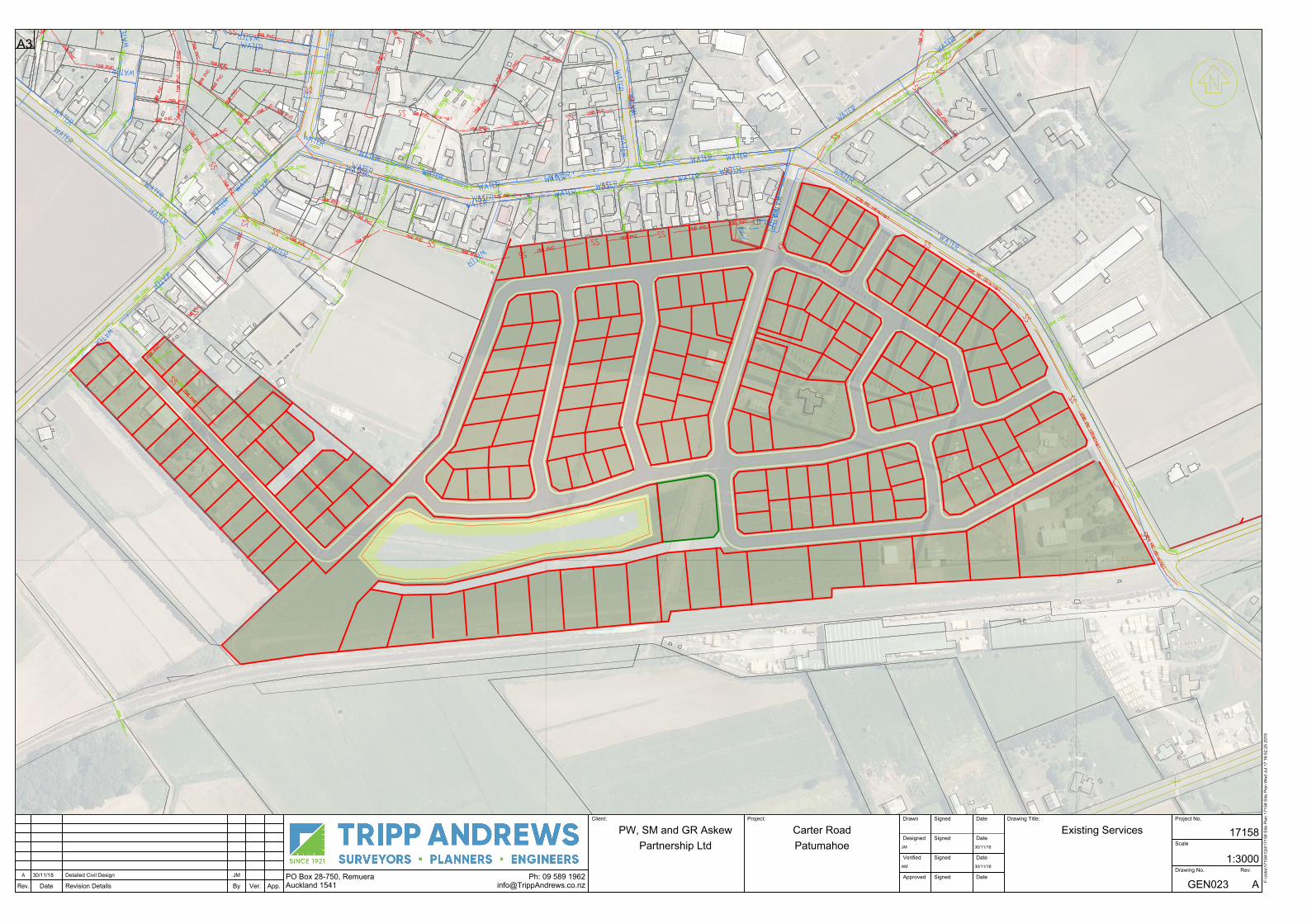
Introduction and Background: Tripp Andrews Surveyors Ltd has been engaged to prepare a Stormwater Management Plan in support of a private plan change on Carter Road, Patumahoe. This report has been prepared to detail and discuss the provisions for the management of the proposed development and the wider catchment. This report covers the proposed methods for managing the current site runoff and the additional development runoff in terms of quality and quantity. The centre of the site is located on Carter Road, Patumahoe with the proposed area encompassing Mauku and Patumahoe Roads. The majority of the site is currently used for grazing of dry-stock, a kiwifruit orchard and a private airstrip and has a small number of existing dwellings, buildings, hard stand and road reserve. The southern portion of the property subject to the proposed subdivision has existing stormwater infrastructure via an open channel drain and is detailed further in this report.
Figure 1: Overall Site Plan
The design proposal is to develop the area with residential housing, plus a small amount of business and commercial use property, to service the rural community. To cater for the increased impervious surfaces for the development, the local stormwater catchment needs to be analysed and the proposed infrastructure designed accordingly. The wider catchment and the directly affected areas will be analysed, this will provide runoff quality and quantity levels that will need to be managed. Once the level of runoff mitigation is found, the necessary assets and methodologies can be designed to provide sufficient stormwater management as per the Auckland Council specifications.
The plans and specifications set out special requirements for the development and these include the following considerations:
- Whether the activity will have an adverse effect on water quality, flood levels, flood storage or any existing infrastructure.
- Whether space provided for stormwater attenuation is safe, does not incorporate steep slopes and has adequate access.
- Whether the development will limit the peak flows to, or less than, pre-development flows for the 2 and 10 year rainfall events.

6
TRIPP ANDREWS SURVEYORS LTD
- Whether the development will adversely affect downstream flows, including the duration of downstream flow, for the 2, 10 and 100 year flows.
- Whether the development provides for adequate and safe overland flow paths within the development.
- Whether assets associated with the development are to be built by the developer and vested in Council.
The key requirements have been identified to comply with the above plans. This includes, but is not limited to, the following:
- Removal of 75% of total suspended solids (TSS) for all of the catchment.
- Attenuation of peak flows from the 10% and 1% AEP Storm to pre-development levels.
- Is flooding an issue and therefore is attenuation of peak flow from the 100 year event to pre-development levels required to prevent increasing downstream flood levels.
1 Existing Site Appraisal: The catchment analysis is undertaken using available data on the Auckland District Council Maps system and website in conjunction with onsite data collected by Tripp Andrews Surveyors Ltd and the details available in the Patumahoe Township Integrated Catchment Management Plan. The data has been analysed to identify catchment areas and factors that would affect the stormwater runoff in the catchment. An analysis of the existing stormwater management and how it integrates with the wider catchment will be done as part of this report. All analysis is undertaken whilst referencing the Auckland Unitary Plan and the Auckland Council Stormwater Code of Practice. It is assumed all development undertaken in the catchment area complies with all relevant legislation, particularly all stormwater runoff has been treated and detained/retained to ensure pre-development flows.
The Regional Network Discharge Consent (NDC) is to help provide an integrated approach in the management of land use activities, including implementing stormwater management at source and providing a more consistent set of requirements aligned with the Auckland Unitary Plan.
One of the aims of the NDC is to help facilitate sustainable future growth and development through a streamlined process that provides clarity and consistent requirements to land developers who connect to the public stormwater network or whose stormwater infrastructure will ultimately become part of the public network, once it is constructed and vested. Policy E 1.3.14 of the Auckland Unitary Plan requires the adoption of the Best Practicable Option (BPO) to minimise the adverse effects of stormwater discharges from the stormwater network. The stormwater management for the proposal follows the BPO design philosophy which aligns with what is proposed under the NDC and due to the greenfield nature of the site the options for stormwater management are open ended.
In order to align this project with the NDC, current BPO stormwater management designs and processes have been chosen for this proposal. This involves using currently accepted stormwater management devices designed with the most relevant information to ensure once the assets are ready to vest, they will align with what is commonplace in the region. This alignment of stormwater management will help achieve the goals of the NDC by having uniformity in the stormwater management systems in the region and this stormwater management plan can be adopted into the NDC once approved.

7
TRIPP ANDREWS SURVEYORS LTD
1.1 Summary of Data Sources and Dates
Existing site appraisal item Source and date of data used
Topography - Auckland Council LIDAR Data (2006) - Topographical survey information
gathered by Tripp Andrews (2017, 2019)
Geotechnical/soil conditions - Landers Geotechnical Appraisal Report (26 October 2018)
Existing stormwater network - Auckland Council Geo maps - Survey information gathered by Tripp
Andrews (2019)
Existing hydrological features - Patumahoe Township Integrated Catchment Management Plan (2006)
Stream, river and coastal erosion - Patumahoe Township Integrated Catchment Management Plan (2006)
Flooding and flow paths - Auckland Council Geo maps - Survey information gathered by Tripp
Andrews (2017)
Ecological / environmental areas - Patumahoe Township Integrated Catchment Management Plan (2006)
Cultural and heritage sites - Ngati Tamaoho Trust Cultural Assessment (2019)
- Ngati Te Ata Cultural Assessment (2019) - Carter Road, Patumahoe: archaeological
assessment (Nov 2018)
Contaminated land To be completed at Resource Consent Stage
1.2 Location and General Information Exiting site element Source and date of data used
Site address Carter Road, Patumahoe, Auckland, 2679
Legal description As per the ‘’Title Structure Plan’’ Attached in the appendices
Current Land Use Predominantly vacant pastoral land
Current building coverage Minimal buildings onsite
Historical Land Use Predominantly vacant pastoral land

8
TRIPP ANDREWS SURVEYORS LTD
1.3 Topography
The topography of the upper catchment areas can be regarded as flat compared to the more rolling terrain near the lower reaches. The proposed development is located on broad gently sloping southerly facing slopes with measured slope angles of less than 13% (See Site Plan in Appendix A). There are some localised depression and mounds on the site. The majority of the site is presently grassed with sparse areas of bare ground, associated with areas of road development works.
1.4 Geotechnical
According to the Institute of Geological and Nuclear Sciences Google Earth QMAP’s, the site is underlain completely by the South Auckland Volcanic Field Lava (Kerikeri Volcanic Group) and is described as fine-grained and coarse-grained, porphyritic, olivine basalt, basanite and hawaiite lava flows. From the Geotechs report and experience in this geology, the basalt is usually at depth and overlain by volcanic ash and tuff deposits, which was confirmed during the hand auger investigation
From the ‘Landers Geotechnical Appraisal Report (26 October 2018)’ the following results were found over the site from hand augers undertaken.
- Topsoil was encountered in all test locations and ranged from 200mm to 400mm, averaging 300mm in thickness;
- Ash deposits were encountered in HA1 (at 0.5m underlying alluvium), HA3, HA4, HA5 and HA6. It typically comprised orange, grey, brown and red silty clay, and clayey silt with trace sand, minor limonite silt inclusions, trace pumiceous clast inclusions and trace weathered basaltic gravel inclusions. Shear strengths indicated that these materials were stiff to hard, and generally insensitive to moderately sensitive. Some variability should be expected with regards to the shear strength of the ash materials, as one shear strength measured in HA4 at 3.5m depth indicated the materials were firm.
- Alluvial materials were encountered in HA1 (to 0.5m depth) and HA2 (in excess of the 5m target depth) and is inferred to be an ancient watercourse / lake deposit, running through a relatively low-lying area on the site. It typically comprised grey, brown, orange and grey silty clays, clayey silts and organic stained clays, with trace organic inclusions, trace sand and minor weakly cemented gravel sized silt clasts. Shear strengths within this material indicated they were stiff to very stiff, becoming hard with depth (beyond 4m in HA2).
- Scala penetrometer testing was completed in HA1 and HA6, where the ash materials became too hard to auger further. Typical (average) blows of the hammer per 100mm of penetration were between 10 and 12.
- Groundwater was only encountered during the time of the investigation in HA2 within the alluvial soils, with standing groundwater levels recorded at 3.0m depth.
1.4.1 Geotechnical Effects on Earthworks and Infrastructure
The impact of the geotechnical condition discussed in the above section on the earthwork’s infrastructure is limited and can be overcome by using best practices and use of a competent contractor. A detailed analysis of the effects and suggested mitigation measures can be found in the ‘Landers Geotechnical Appraisal Report (26 October 2018)’ section 9.3.

9
TRIPP ANDREWS SURVEYORS LTD
1.4.2 Soakage and Further Geotechnical Requirements
As the area is underlain by the South Auckland Volcanic Field Lava there is a possibility of soakage as method of Stormwater disposal. There is also an inherent flooding risk on the site and the general requirement to mitigate downstream effects will require management, this is discussed further in this report. In order to mitigate flooding risk a centralised system will be proposed and therefore detailed geotechnical information will need to be obtained at the resource consent stage to support soakage use in the proposed area and further individual areas. To support this the following is stated in the ICMP.
‘FDC does not have defined or designated stormwater soakage areas within this particular catchment, or within the District. Some areas of the residential and business zoned land have no present public primary reticulated stormwater system, in which stormwater disposal is managed totally on site by soakage to ground. Within Patumahoe the areas where there is no service are discrete. At those locations it is assumed that all stormwater is managed through ground soakage.
In rural-residential zoned land, lots may not necessarily be provided with a fully piped reticulated primary system. Subdivisions are approved on a case by case basis with respect to the need for a fully piped primary system. The current developed residential and business zoned areas in Patumahoe
that are not provided with a public piped primary reticulated system are shown in Figure A8 of the Appendix.’
1.5 Existing Drainage Features and Stormwater Infrastructure 1.5.1 Catchments
The catchment analysis is undertaken using available data on the Auckland District Council Maps system and website in conjunction with onsite data collected by Tripp Andrews Surveyors Ltd and the Patumahoe Integrated Catchment Management Plan (ICMP). The data has been analysed to identify catchment areas and factors that would affect the stormwater runoff in the catchment. An analysis of the existing stormwater management and how it integrates with the wider catchment will be done as part of this report. All analysis is undertaken whilst referencing the Auckland Unitary Plan and the Auckland Council Stormwater Code of Practice. It is assumed all development undertaken in the catchment area complies with all relevant legislation, in particular, all stormwater runoff has been treated and detained/retained to ensure pre-development flows.
From analysis of the contours of the Auckland Council Geomaps System, there are three sub catchments for the proposed development site that feature existing drainage and stormwater features, these catchments are shown below;

10
TRIPP ANDREWS SURVEYORS LTD
Figure 1: Carter Road Sub-Catchment
The Catchment is identified by using the ridges and valleys of pre-development contours in the topographical information to ascertain where flows will be conveyed during storm events. From the aerial photograph, most of the development of the area is contained in one large catchment (Catchment 1), with two smaller catchment areas (Catchments 2 and 3) of the development, belonging to adjacent catchments. A summary of the relevant catchment areas are as follows;
Catchment 1: 27.37 Ha
Catchment 1 is the major catchment of the proposed development. It is bounded by Patumahoe and Mauku Roads and discharges to the stormwater drain running along the railway tracks and into Mauku Stream. The majority of this catchment is contained within the development site and therefore limited outside runoff will enter the development site.
Catchment 2: 4.01 Ha
Catchment 2 is the head of the catchment to the north of Catchment 1. This catchment currently flows to Patumahoe Road and then further north along some minor tributaries before also entering Mauku Stream. As the catchment runoff currently ends in the same Mauku stream environment, re-diverting to Catchment 1 as part of the development will have less than minor effects overall on the downstream environment.
Catchment 3: 7.07 Ha
Catchment 3 is the head of the catchment directly east of Catchment 1. This catchment currently discharges to Whangamaire Stream via sheet runoff and overland flow paths.
The Catchment area is made up of several man-made drainage channels and piped networks to discharge the runoff to the Mauku or Whangamaire catchments.
Catchment 1: 27.37 Ha
Catchment 2: 4.01 Ha
Catchment 3: 7.07 Ha
11
TRIPP ANDREWS SURVEYORS LTD
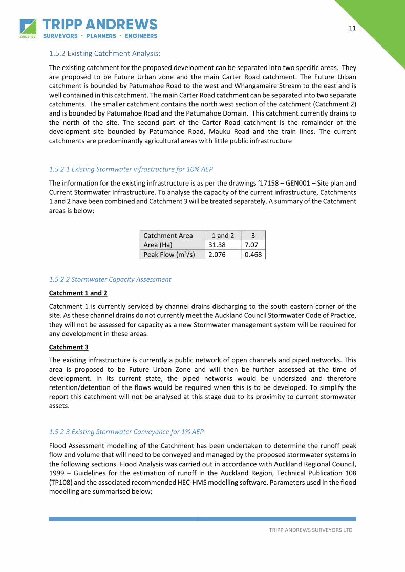
1.5.2 Existing Catchment Analysis:
The existing catchment for the proposed development can be separated into two specific areas. They are proposed to be Future Urban zone and the main Carter Road catchment. The Future Urban catchment is bounded by Patumahoe Road to the west and Whangamaire Stream to the east and is well contained in this catchment. The main Carter Road catchment can be separated into two separate catchments. The smaller catchment contains the north west section of the catchment (Catchment 2) and is bounded by Patumahoe Road and the Patumahoe Domain. This catchment currently drains to the north of the site. The second part of the Carter Road catchment is the remainder of the development site bounded by Patumahoe Road, Mauku Road and the train lines. The current catchments are predominantly agricultural areas with little public infrastructure
1.5.2.1 Existing Stormwater infrastructure for 10% AEP
The information for the existing infrastructure is as per the drawings ‘17158 – GEN001 – Site plan and Current Stormwater Infrastructure. To analyse the capacity of the current infrastructure, Catchments 1 and 2 have been combined and Catchment 3 will be treated separately. A summary of the Catchment areas is below;
Catchment Area 1 and 2 3 Area (Ha) 31.38 7.07 Peak Flow (m³/s) 2.076 0.468
1.5.2.2 Stormwater Capacity Assessment
Catchment 1 and 2
Catchment 1 is currently serviced by channel drains discharging to the south eastern corner of the site. As these channel drains do not currently meet the Auckland Council Stormwater Code of Practice, they will not be assessed for capacity as a new Stormwater management system will be required for any development in these areas.
Catchment 3
The existing infrastructure is currently a public network of open channels and piped networks. This area is proposed to be Future Urban Zone and will then be further assessed at the time of development. In its current state, the piped networks would be undersized and therefore retention/detention of the flows would be required when this is to be developed. To simplify the report this catchment will not be analysed at this stage due to its proximity to current stormwater assets.
1.5.2.3 Existing Stormwater Conveyance for 1% AEP
Flood Assessment modelling of the Catchment has been undertaken to determine the runoff peak flow and volume that will need to be conveyed and managed by the proposed stormwater systems in the following sections. Flood Analysis was carried out in accordance with Auckland Regional Council, 1999 – Guidelines for the estimation of runoff in the Auckland Region, Technical Publication 108 (TP108) and the associated recommended HEC-HMS modelling software. Parameters used in the flood modelling are summarised below;

12
TRIPP ANDREWS SURVEYORS LTD
Catchment Area 1 and 2 3 Area (Ha) 31.38 7.07 TP108 Peak Flow (m³/s) 8.029 1.807 TP108 Volume (1000m³) 48.4 10.9 HEC Peak Flow (m³/s) 6.4 1.2 Hec Volume (1000m³) 39.9 8.6
From this table, TP108 has the greater volume and flow rates and therefore will be used for the design of the stormwater management devices.
1.5.3 Stormwater Model Setup 1.5.3.1.1 Precinct Catchments
Catchment delineation within the proposed development is currently separated as per the catchment map in Appendix A. It is assumed that runoff from the entire development will drain to the future stormwater management systems.
1.5.3.1.2 External Catchments
The proposed Carter Road Development site is in the unique position that the site will generate all the runoff and therefore will be fully contained in the development site.
1.5.3.1.3 Catchment Runoff Parameters
The Catchment CN values were managed within the model based on an assumed impervious percentage. Residential areas were typically assumed to be 70% impervious, and road reserves were assumed to be 80% impervious. Initial abstractions represent the depth of water that an area can infiltrate at the beginning of a storm. Impervious areas were assumed to have zero initial abstraction, and pervious areas were assumed to have 5mm. A composite initial abstraction was determined based on the proportion of impervious cover. Due to the nature of the volcanic soils and their current pastural use, a CN value of 61 was used. This was also indicated by the Lander Geotechnical assessment 26.8.18.
1.5.3.1.4 Rainfall
Rainfall depth data was taken from the Rain Contour Maps provided in the Auckland Regional Council, 1999 – Guidelines for the estimation of runoff in the Auckland Region, Technical Publication 108 (TP108) and is detailed in the section 3.2.1 above.
1.5.3.1.5 Results
The runoff volumes from the catchments are shown below, this is for both the TP108 method and using HEC HMS modelling of the catchments. From the results it is found that both TP108 an HEC have similar values. TP108 has slightly higher values, so these will be used for the proposed stormwater management solutions. The results of this analysis are seen as conservative as it has assumed all pipes will be full and have no capacity, regardless of size, due to downstream outlets being fully submerged by the detention basin.

13
TRIPP ANDREWS SURVEYORS LTD
1.5.3.1.6 Flood Plain
The site at Carter Road currently has an extended flood plain running through the site, this is due to a slight depression running around the channel drain area and a low point to the west of the road formation. As part of the proposal, the earthworks will reduce the amount of flooding on the site and this volume will be catered for in the stormwater management devices.
1.6 Receiving Environment The Receiving environment for the proposed development is the Mauku Tributary which is not covered under the Patumahoe ICMP. In the absence of a catchment wide stormwater management system, the requirement for development are to:
- Treat stormwater discharge in accordance with GD01. - Minimise changes to the pre-development hydrological regime (i.e. attenuating stormwater
flows). - Consider low impact design (i.e. water sensitive design).
Complying with the above requirements can deliver much of the intent of the Auckland Unitary Plan (OiP) however, stormwater management in the Auckland Region has advanced significantly since the granting of this consent. The recently notified Auckland Wide Network Discharge consent, once granted, will supersede the existing consent held. This will mean the discharge conditions and connection standards will be in line with the stormwater management approach of the AUP OiP.
1.7 Existing Hydrological Features
The site contains numerous surface water features in the catchment. These features include the following;
Farm Drainage Channel:
An engineered channel to catch runoff from the grazing land and channel to the overland flow path in the south west of site. The channels run East-West across the central low point of the site and is cleared out with an excavator to maintain the drainage shape. The quality of the drainage channel is low as it need to be cleared frequently, and no riparian vegetation has even been established along the channel. Evidence of constant cleaning out of the channel is visible on the site and from aerial photography on the Auckland council GIS viewer, and has been verified by the landowner.
The proposed new drainage system would be more effective than what is currently onsite in managing stormwater flows and achieving a higher level of sediment and contaminant removal.
Road Drainage Channel:
There is a road drainage channel (shoulder drain) along both sides of Carter road, which conveys flow to the low point of the road near the farm channel drainage. These channel drains area standard road channel drain and hold no value to the proposal.
Culverts
There are Three culverts crossing the drainage channel these areas identified below

14
TRIPP ANDREWS SURVEYORS LTD
- Road Culvert, Culvert under Carter Road for road crossing - Farm Culvert 1, culvert for farm crossing - Farm Culvert 2, culvert for farm crossing
These culverts tend to have no headwall type structures, and are what would be classed as farm culverts. New culverts will be required to be installed as per the Stormwater Code of Practice – as part of the future subdivision of the site.
Pasture/Cultivated Land
The majority of the site is either in pasture or cultivated land that lacks any natural hydrological features. This is due to the extensive farming on the property removing any slight depressions that could convey any flow other than sheet flow.
Kiwifruit Orchard
The portion of the site has been used for Kiwifruit growing and has been well developed with the kiwi fruit plant the vegetated wind breaks
1.8 Flooding and Flow Paths See attached Flood Risk Assessment.
1.9 Coastal Inundation Not applicable to this site.
1.10 Biodiversity
The Site has some farm channel drainage running the rough the site, these area manmade channels which hold little ecological value. The uniform pastureland of much of the catchment provides poor habitat for native flora and fauna. Growth offers significant opportunity for improving riparian and aquatic habitat and in the case of the proposal this will be greatly increased.
1.11 Cultural and Heritage Sites
As per the Carter Road, Patumahoe: archaeological assessment (Nov 2018) completed by CFG Heritage.
‘No evidence of pre-1900 archaeology or heritage, or significant 20th century heritage, was found in the proposed development, either during the historic research or the field survey. The most suitable areas for pre-European Maori horticulture is in the north eastern portion of the proposed development (Section 1) but there is no evidence that this was ever undertaken here. There was no evidence of the Patumahoe train station, or any structures which could relate to its use.’
1.12 Contaminated Land
As part of the Resource Consent application a detailed site investigation report will be undertaken.

15
TRIPP ANDREWS SURVEYORS LTD
The historical land use of the area will be assessed and samples from the site taken. A report will be completed and provided as evidence with the resource consent application.
2 Development Summary and Planning Context 2.1 Regulatory and Design Requirements
Requirement Source and date of data used
Unitary Plan – SMAF hydrology mitigation Not Applicable
High Contaminant Generating Areas Not Applicable
Natural Hazards AUP Chapter E36 requirements
Auckland Unitary Plan Precinct Not Applicable
Existing catchment Management Plan Not applicabe, Patumahoe Township Integrated Catchment Management Plan (2006) used for refernce
Auckland Council Regionwide Network Discharge Consent
Not Applicable
3 Mana Whenua Matters 3.1 Identification and Incorporation of Mana Whenua Values
We have received reports form Ngati Tamaoho and Ngati Te Ata with both detailing their recommendation on the water management in the site. Water is very important to Maori and the proposed collection, conveyance and treatment of water is undertaken with the guidance of the assessments provided.
4 Stakeholder Engagement and Consultation Iwi:
- We have met both Ngati Tamaoho Trust and Ngati Te Ata on site in November 2018.
- Both Iwi’s have submitted reports in support of the application.
Auckland Transport:
- Stantec made contact with Auckland Transport in November 2018 via email.
- On the 16th on January 2019 with had a site specific meeting with Katherine Dorofaeff, Mat Colins and Alastair Lovell. Saul, Ian Munro and Bridget Gilbert were also present at this

16
TRIPP ANDREWS SURVEYORS LTD
meeting.
- Katherine from Auckland Transport issued consultation notes from this meeting. Each point has been addressed in the Traffic Assessment report from Stantec
Watercare:
- Tripp Andrews made contact with Watercare in November 2018.
- On 5th November Jack MacDonald met with Vinay Bhan, Ilze Gotelli (Head of Development) and Kerryn Swanepol.
Kiwirail:
- Stantec directly consulted with Kiwirail. Pam Bulter (Senior RMA Advisor) has responded with Reverse Sensitivity (Noise and Vibration setbacks) via email.
Neighbouring owners:
- The Askew Family have made contact a number of times with all relevant neighbouring parties.
- The first meeting was held in Patumahoe with all neighbours at the Patumahoe Rugby Club in August 2018 to find out whether neighbours would support the application or not. Each neighbour was either in support of the application or neutral to the application proceeding.
- Nick and Peter on the 18th September have been back to see each neighbour regarding progress of the application with an update that the application is due to be submitted. The only neighbour that they have not been able to contact is Rett Robert Hunter and Bronwyn Meurant at 104 Patumahoe Road.
5 Proposed Development 5.1 Location and Area See Drawing ‘17158 – GEN001 – Site Locality Plan’ for location and area details.
5.2 Purpose of the Development
This section summarises the key aspects of the proposed stormwater systems and evaluation criteria that was adopted for this development.
The design has been based on a number of principles established in the overall Carter Road proposal. The design principles require potential adverse effects to be avoided, remedied or mitigated where they are more than minor, and include:
- The design will incorporate the total stormwater management system (collection and conveyance network, treatment devices).
- The objective of the stormwater management system is to provide a best practicable option (BPO) to avoid, remedy or mitigate more than minor adverse environmental effects, determined through a robust evaluation of options.
- The design shall include full consideration of stormwater operational implications throughout the design life.

17
TRIPP ANDREWS SURVEYORS LTD
- The design shall best practicably mimic the existing hydrologic regime and setting, to deliver outcome objectives that remedy or mitigate adverse environmental effects. The design shall also consider any potential measures to improve current problems within the project area.
- Overarching low impact design and safety in design methologies.
5.3 Site Layout and Urban Form See Drawing ‘17158 – SW001 – Stormwater proposal’ for the proposed site layout.
5.4 Earthworks See Section 6 of the infrastructure report for earthworks requirements
6 Stormwater Management 6.1 Principles of Stormwater Management 6.1.1 Original Principles
This section summarises the key aspects of the proposed stormwater systems and evaluation criteria that was adopted for this development.
The following design standards and guidelines were referenced for the stormwater system and stream works design for the project:
- Stormwater Management Devices: Design Guidelines Manual, ARC Technical Publication No. 10 (ARC TP10), Second Edition, 2003.
- Stormwater Management Devices in the Auckland Region, Guideline Document 2107/001 Version 1 (GD01) Dec 2017.
- Water Sensitive Design for Stormwater, March 2015, Guideline Document 2015/004 (GD04). - The Auckland Council Code of Practice for Land Development and Subdivision, Stormwater. - Guidelines for Stormwater Runoff Modelling in the Auckland Region, ARC Technical
Publication No. 108 (ARC TP108), 1999. - NZS3725: Loads on Buried Concrete Pipes, 1989. - Climate Change Effects and Impacts Assessment - A Guidance Manual for Local Government
in New Zealand, Ministry for the Environment, Second edition, 2008.
Stormwater runoff volumes and peak flows were determined using ARC Design Guideline TP108 as described earlier. Areas included for stormwater treatment include:
- All new (additional) road pavement surfaces. - Existing surfaces whether impermeable or permeable. - An allowance for maximum probable development of all sites.
Permanent treatment devices are designed to Stormwater Management Devices in the Auckland Region, Guideline Document 2107/001 Version 1 (GD01) Dec 2017, using the Best Practicable Option (BPO) approach. All the devices proposed in this design provide water quality treatment to 75% removal of Total Suspended Solids (TSS) efficiency. The designs will provide flow attenuation and extended detention.

18
TRIPP ANDREWS SURVEYORS LTD
The proposed treatment device to treat stormwater runoff for the catchment is to be located in the lower part of the catchment in close proximity to the receiving stream environment.
The Auckland Unitary Plan (OiP), particularly in E1.3(10) Integrated Stormwater Management, requires greenfield development to take an integrated stormwater management approach. In taking an integrated stormwater management approach have regard to the following:
a) The nature and scale of the development and practical and cost considerations, recognising:
I. Greenfield and comprehensive brownfield development generally offer greater opportunity than intensification and small-scale redevelopment of existing areas.
II. Intensive land uses such as high-intensity residential, business, industrial and roads generally have greater constraints.
III. Site operational and use requirements may preclude the use of an integrated stormwater management approach.
b) The location, design, capacity, intensity and integration of sites/development and infrastructure, including roads and reserves, to protect significant site features and hydrology and minimise adverse effects on receiving environments.
c) The nature and sensitivity of receiving environments to the adverse effects of development, including fragmentation and loss of connectivity of rivers and streams, hydrological effects and contaminant discharges and how these can be minimised and mitigated, including opportunities to enhance degraded environments.
d) Reducing stormwater flows and contaminants at source prior to the consideration of mitigation measures and the optimisation of on-site and larger communal devices where these are required.
e) The use and enhancement of natural hydrological features and green infrastructure for stormwater management where practicable. These requirements are reflected in Auckland Council’s Water Sensitive Design guideline (GD04), which sets out a process for delivering water sensitive design in the Auckland Region.
Water Sensitive Design is an inter-disciplinary design approach to urban planning and development which provides opportunities for integration of land use and freshwater management and aims to protect and enhance natural freshwater systems, by sustainably managing water sources and mimicking natural processes. (Auckland Council, 2015).
There are four key Water Sensitive Design principles in GD04:
1. Promote interdisciplinary planning and design.
2. Protect and enhance the values and functions of natural ecosystems.
3. Address stormwater effects as close to source as possible.
4. Mimic natural systems and processes for stormwater management.
This SMP provides guidance on how potential water sensitive design can be applied to the Carter Road development.
6.1.2 Updated Principles
This proposal will use the standard principles for stormwater management.
19
TRIPP ANDREWS SURVEYORS LTD
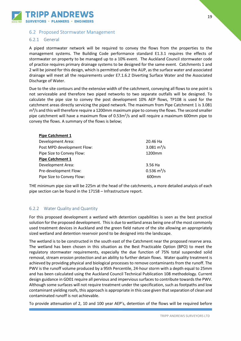
6.2 Proposed Stormwater Management 6.2.1 General
A piped stormwater network will be required to convey the flows from the properties to the management systems. The Building Code performance standard E1.3.1 requires the effects of stormwater on property to be managed up to a 10% event. The Auckland Council stormwater code of practice requires primary drainage systems to be designed for the same event. Catchments 1 and 2 will be joined for this design, which is permitted under the AUP, as the surface water and associated drainage will meet all the requirements under E7.1.6.2 Diverting Surface Water and the Associated Discharge of Water.
Due to the site contours and the extensive width of the catchment, conveying all flows to one point is not serviceable and therefore two piped networks to two separate outfalls will be designed. To calculate the pipe size to convey the post development 10% AEP flows, TP108 is used for the catchment areas directly servicing the piped network. The maximum from Pipe Catchment 1 is 3.081 m³/s and this will therefore require a 1200mm maximum pipe to convey the flows. The second smaller pipe catchment will have a maximum flow of 0.53m3/s and will require a maximum 600mm pipe to convey the flows. A summary of the flows is below;
Pipe Catchment 1 Development Area: 20.46 Ha Post MPD development Flow: 3.081 m³/s Pipe Size to Convey Flow: 1200mm Pipe Catchment 1 Development Area: 3.56 Ha Pre-development Flow: 0.536 m³/s Pipe Size to Convey Flow: 600mm
THE minimum pipe size will be 225m at the head of the catchments, a more detailed analysis of each pipe section can be found in the 17158 – Infrastructure report.
6.2.2 Water Quality and Quantity
For this proposed development a wetland with detention capabilities is seen as the best practical solution for the proposed development. This is due to wetland areas being one of the most commonly used treatment devices in Auckland and the green field nature of the site allowing an appropriately sized wetland and detention reservoir pond to be designed into the landscape.
The wetland is to be constructed in the south east of the Catchment near the proposed reserve area. The wetland has been chosen in this situation as the Best Practicable Option (BPO) to meet the regulatory stormwater requirements, especially the due function of 75% total suspended solid removal, stream erosion protection and an ability to further detain flows. Water quality treatment is achieved by providing physical and biological processes to remove contaminants from the runoff. The PWV is the runoff volume produced by a 95th Percentile, 24-hour storm with a depth equal to 25mm and has been calculated using the Auckland Council Technical Publication 108 methodology. Current design guidance in GD01 require all pervious and impervious surfaces to contribute towards the PWV. Although some surfaces will not require treatment under the specification, such as footpaths and low contaminant yielding roofs, this approach is appropriate in this case given that separation of clean and contaminated runoff is not achievable.
To provide attenuation of 2, 10 and 100 year AEP’s, detention of the flows will be required before

20
TRIPP ANDREWS SURVEYORS LTD
discharge to the downstream environment. 1% AEP detention has been included to ensure streambed protection downstream of the discharge point occurs. The detention basin will extend from the wetland and finish with a 3-5m buffer to the edge of the reserve area and will be part of a treatment suite, including a piped stormwater system for 10% AEP conveyance and a network of overland flow paths to convey storm flows to the pond during 1% AEP.
Runoff from events up to and including the 10% AEP will be collected via a piped system and discharged into the ponds via the proposed outlet structure, to enable the required detention to be collected. The wetland has been designed to ensure peak velocities of 0.1 m/s for up to 50% AEP storms, and 0.5m/s for up to 10% AEP storms. The wetland will have outlets for the 2, 10 and 1% AEP’s to ensure the post development flows can be retained and flows returned to predevelopment levels before exiting the development site.
POND DESIGN DETAILS
Catchment Area: 31.38 Ha Pre-Development Volume: 28,000 m3 Post Development Volume: 48,000 m3
Volume to be detained: 20,000 m3
TREATMENT CALCULATIONS
Treatment Area: 13.38 Ha Bathymetry: Sinuous Permanent Water Volume: 3352 m³ (90 %lie, 25mm = 2234 x 1.5 for stream protection) Minimum Wetland Area: 3352 m² (0.5 as ponding coeff)
From the above calculations, a forebay of over 1324.5 m³ will be used for both detention and hard sediment removal. The flows will then overtop the forebay and flow through the wetland and be discharged to the stream. From the natural contours of the site a wetland area can fit in the natural site; an example layout can be found in Appendix A. All detailed design will be carried out as part of the Engineering Plan Approvals stage of any part of the development.
6.2.3 Stream Hydrology
The proposed development site will discharge to the Mauku Stream catchment. The Mauku Stream is included in the High Use Stream Management area overlay in the AUP, which means the stream is under pressure from demands to take water or use water. One of the objectives of the stormwater management design is to ensure water levels will be maintained in the stream and therefore all post development flows up to a 1% AEP will be managed to pre-development levels. This design philosophy aligns with the management approach for streams in the ‘high use stream management areas’’
‘The purpose of this management area is to ensure that taking is enabled while maintaining the life-supporting capacity and amenity values of these streams. Accordingly, other than the ability to take water as permitted by section 14 of the RMA, the majority of takes will need to be carefully evaluated and managed, generally through the resource consent process, to ensure that the use, ecological and amenity values of these rivers and streams are maintained and where possible enhanced’
The only significant alteration to the stream hydrology is the inclusion of Catchment 2 (Figure 1) which
21
TRIPP ANDREWS SURVEYORS LTD
is currently the head of part of the Whangamaire catchment. As the entire site will be managed for a 1% AEP in one central location flow rates can be manged in accordance with the site requirements. To ensure there is no increased flood risk on the downstream properties the flow rate at the outlet can be manged to ensure the flow rate will not exceed the flow rate generated by Catchment 1 (figure 1). The detention requirements for the entire is proposed so this will ensure no adverse effects downstream.
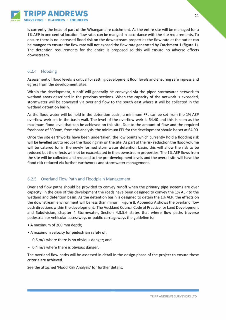
6.2.4 Flooding
Assessment of flood levels is critical for setting development floor levels and ensuring safe ingress and egress from the development sites.
Within the development, runoff will generally be conveyed via the piped stormwater network to wetland areas described in the previous sections. When the capacity of the network is exceeded, stormwater will be conveyed via overland flow to the south east where it will be collected in the wetland detention basin.
As the flood water will be held in the detention basin, a minimum FFL can be set from the 1% AEP overflow weir set in the basin wall. The level of the overflow weir is 64.40 and this is seen as the maximum flood level that can be achieved on this site. Due to the amount of flow and the required freeboard of 500mm, from this analysis, the minimum FFL for the development should be set at 64.90.
Once the site earthworks have been undertaken, the low points which currently hold a flooding risk will be levelled out to reduce the flooding risk on the site. As part of the risk reduction the flood volume will be catered for in the newly formed stormwater detention basin, this will allow the risk to be reduced but the effects will not be exacerbated in the downstream properties. The 1% AEP flows from the site will be collected and reduced to the pre-development levels and the overall site will have the flood risk reduced via further earthworks and stormwater management.
6.2.5 Overland Flow Path and Floodplain Management
Overland flow paths should be provided to convey runoff when the primary pipe systems are over capacity. In the case of this development the roads have been designed to convey the 1% AEP to the wetland and detention basin. As the detention basin is designed to detain the 1% AEP, the effects on the downstream environment will be less than minor. Figure 8, Appendix A shows the overland flow path directions within the development. The Auckland Council Code of Practice for Land Development and Subdivision, chapter 4 Stormwater, Section 4.3.5.6 states that where flow paths traverse pedestrian or vehicular accessways or public carriageways the guideline is:
• A maximum of 200 mm depth;
• A maximum velocity for pedestrian safety of:
- 0.6 m/s where there is no obvious danger; and
- 0.4 m/s where there is obvious danger.
The overland flow paths will be assessed in detail in the design phase of the project to ensure these criteria are achieved.
See the attached ‘Flood Risk Analysis’ for further details.

22
TRIPP ANDREWS SURVEYORS LTD
6.2.6 Development Staging
All major infrastructure will be constructed in the first stage to ensure all services can installed prior to any further subdivision.
6.3 Hydraulic Connectivity
The development is a greenfield vacant site subdivision with potential to change though out the design process. The road networks should be designed to convert the 1% AEP flows to the detention basin. If required, earthworks will be competed to ensure all areas of the site flow to the detention basin and the 1% AEP flows will contained with the required reserve. Detailed flood modelling will be undertaken at the resource consent stage to ensure compliance with the relevant requirements.
6.4 Asset Ownership
As the works will be required to service a development of the proposed size, the stormwater conveyance and treatment systems will be installed by the developer, at their cost, to ensure there is no increased effects on the downstream environment during the building construction stage. The cost of maintenance and upkeep until the assets can be vested to the council will also be at the developer’s cost.
6.5 Ongoing Maintenance Requirements
Operations, maintenance and monitoring of the proposed stormwater system are critical in ensuring that the short and long-term performance of the system is maintained. In addition, the AUP requires that the development includes an effective monitoring and maintenance programme, which addresses sediment loads, treatment required for the protection of long-term water treatment qualities of the wetland and the monitoring and maintenance required to maintain the necessary treatment levels required under the Stormwater Code of Practice. Maintenance and monitoring should focus on preventing sediment entering and accumulating within the storage and treatment zones. Excess sediment accumulation may reduce both the void space and treatment efficiency. Should monitoring identify reduced storage and treatment, rehabilitation of the zones may be required.
6.6 Implementation of Stormwater Network
All the stormwater treatment and detention works will be completed under the Engineering Plan application process. These works will be installed, monitored, inspected and signed off before vesting to Auckland Council. As the site will be vacant lots the ground will be stabilised, and no extra runoff or sediment is expected to enter the stormwater system.
Operations, maintenance and monitoring of the proposed stormwater system are critical in ensuring that the short and long-term performance of the system is maintained. In addition, the AUP requires that the development includes an effective monitoring and maintenance programme, which addresses sediment loads, treatment required for the protection of long-term water treatment qualities of the wetland and the monitoring and maintenance required to maintain the necessary treatment levels required under the Stormwater Code of Practice. Maintenance and monitoring should focus on preventing sediment entering and accumulating within the storage and treatment
23
TRIPP ANDREWS SURVEYORS LTD
zones. Excess sediment accumulation may reduce both the void space and treatment efficiency. Should monitoring identify reduced storage and treatment, rehabilitation of the zones may be required.
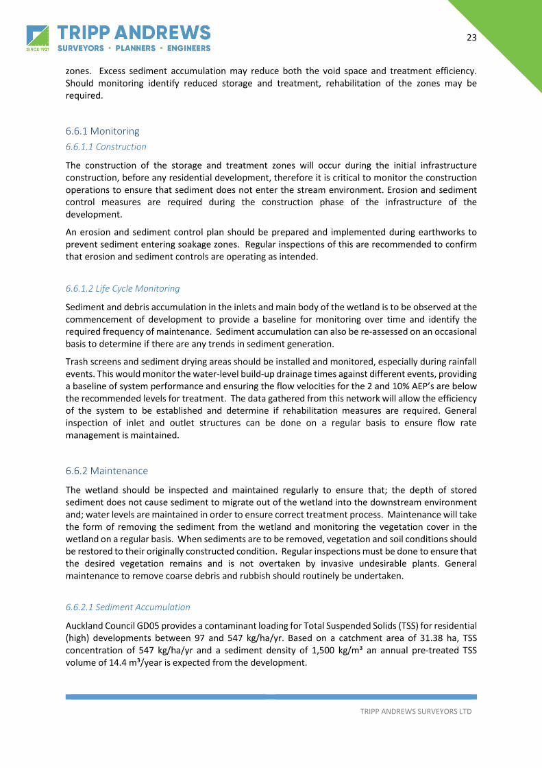
6.6.1 Monitoring 6.6.1.1 Construction
The construction of the storage and treatment zones will occur during the initial infrastructure construction, before any residential development, therefore it is critical to monitor the construction operations to ensure that sediment does not enter the stream environment. Erosion and sediment control measures are required during the construction phase of the infrastructure of the development.
An erosion and sediment control plan should be prepared and implemented during earthworks to prevent sediment entering soakage zones. Regular inspections of this are recommended to confirm that erosion and sediment controls are operating as intended.
6.6.1.2 Life Cycle Monitoring
Sediment and debris accumulation in the inlets and main body of the wetland is to be observed at the commencement of development to provide a baseline for monitoring over time and identify the required frequency of maintenance. Sediment accumulation can also be re-assessed on an occasional basis to determine if there are any trends in sediment generation.
Trash screens and sediment drying areas should be installed and monitored, especially during rainfall events. This would monitor the water-level build-up drainage times against different events, providing a baseline of system performance and ensuring the flow velocities for the 2 and 10% AEP’s are below the recommended levels for treatment. The data gathered from this network will allow the efficiency of the system to be established and determine if rehabilitation measures are required. General inspection of inlet and outlet structures can be done on a regular basis to ensure flow rate management is maintained.
6.6.2 Maintenance
The wetland should be inspected and maintained regularly to ensure that; the depth of stored sediment does not cause sediment to migrate out of the wetland into the downstream environment and; water levels are maintained in order to ensure correct treatment process. Maintenance will take the form of removing the sediment from the wetland and monitoring the vegetation cover in the wetland on a regular basis. When sediments are to be removed, vegetation and soil conditions should be restored to their originally constructed condition. Regular inspections must be done to ensure that the desired vegetation remains and is not overtaken by invasive undesirable plants. General maintenance to remove coarse debris and rubbish should routinely be undertaken.
6.6.2.1 Sediment Accumulation
Auckland Council GD05 provides a contaminant loading for Total Suspended Solids (TSS) for residential (high) developments between 97 and 547 kg/ha/yr. Based on a catchment area of 31.38 ha, TSS concentration of 547 kg/ha/yr and a sediment density of 1,500 kg/m³ an annual pre-treated TSS volume of 14.4 m³/year is expected from the development.

24
TRIPP ANDREWS SURVEYORS LTD
6.7 Dependencies
All the stormwater treatment and detention works will be completed under the Engineering Plan application process as they should be installed under the first stage. Once the treatment and detention requirements are In place or accounted for, the resto of the works will not be dependent on ay other stormwater works
6.8 Risks
As the proposed retention basin is 20,000m3 dam safety design guidelines and monitoring will be required. The key objective for dam safety being that people, property and the environment (present and future), be protected from the harmful effects of dam failure or an uncontrolled release of reservoir contents. In the case of the detention basin and wetland, this will be below the ground, therefore the considerations need to be for this type of basin. The detailed design for the stormwater management devices will include specialist design from Geotech, structural and civil to ensure all safety in design requirements will be met.
See risk matrix of the potential hazards in Appendix C.
7 Departures from Regulatory or Design Codes There are no major departures from the regulatory codes in this design. This is one of the major advantages of this design.

25
TRIPP ANDREWS SURVEYORS LTD
8 Conclusion and Recommendation for Future Work This report details the current state and the proposed development state of the stormwater runoff and management in order to support the private plan change for the Carter Road site. From this report the following conclusions can be made;
Stormwater runoff from the 50%, 10% to 1% AEP storm events can be appropriately managed through the piped network, overland flow path network and wetland and detention basin, on site, prior to any discharge to the downstream environment. From this on-site management, all pre-development flow levels will be maintained.
The wetland has been designed to meet the regulatory requirements for stormwater quality for the entire Catchment of the Carter Road section of the development.
The future predicted flood level will be tied to the overflow of the wetland detention basin, this is currently designed at 64.40.
All habitable floor levels are to have 500mm freeboard above the 1% AEP, this also considers the piped system being at full capacity due to the piped network outlets being fully submerged.
All Cost for the construction of the stormwater asserts will be at the developers cost
Overall, the stormwater management that is provided in this plan ensures a high level of robustness for stormwater management in the Carter Road development.
Further detailed analysis of the underlying geotechnical properties, stormwater reticulation and earthwork formation of the site will be required at resource content stage.
Should you have any questions regarding any points addressed in this report or require any further information, please don’t hesitate to contact me.
Report prepared by
Jack MacDonald Civil Engineer 021 0851 8679 Tripp Andrews Surveyors Ltd

26
TRIPP ANDREWS SURVEYORS LTD
Appendix A: Appendix A:
- Engineering Drawings o 17158 – GEN001 – Site Locality Plan o 17158 – GEN023 – Current infrastructure o 17158 – SW001 – Stormwater Proposal o 17158 – SW002 – Stormwater Pipe Catchments o 17158 – Title location plan o 17158 – SW023 – Hydrological Features

CLIVE HOWE ROAD
AGEN001
1:3000
17158JM 30/11/18
AM 30/11/18
DateApproved Signed
Date
Date
Date
Designed
Verified
Drawn
Signed
Signed
Signed Drawing Title:
Drawing No. Rev.
Scale
Project No.Project:
Rev. Date Revision Details App.Ver.By
Client:
A 30/11/18 Detailed Civil Design JM
F:\J
obs\
1715
8\12
d\17
158
Site
Pla
n 17
158
Site
Pla
n W
ed J
ul 1
7 16
:48:
03 2
019
Carter RoadPatumahoe
Location PlanPW, SM and GR AskewPartnership Ltd
A3
PO Box 28-750, RemueraAuckland 1541
Ph: 09 589 [email protected]
CLIVE HOWE ROAD
AGEN023
1:3000
17158JM 30/11/18
AM 30/11/18
DateApproved Signed
Date
Date
Date
Designed
Verified
Drawn
Signed
Signed
Signed Drawing Title:
Drawing No. Rev.
Scale
Project No.Project:
Rev. Date Revision Details App.Ver.By
Client:
A 30/11/18 Detailed Civil Design JM
F:\J
obs\
1715
8\12
d\17
158
Site
Pla
n 17
158
Site
Pla
n W
ed J
ul 1
7 16
:52:
25 2
019
Carter RoadPatumahoe
Existing ServicesPW, SM and GR AskewPartnership Ltd
A3
PO Box 28-750, RemueraAuckland 1541
Ph: 09 589 [email protected]

CLIVE HOWE ROAD
450Ø RCRRJ Class 2
600Ø RCRRJ Class 2
675Ø
SWMH
SWMHSWMH
SWMH
375Ø RCRRJ Class 2375Ø
RC
RR
J Class 2
525Ø RCRRJ Class 2
SWMH
SWMH
SWMHSWMH
375Ø375Ø
SWMH
SWMH
SWMH
225Ø
375Ø
375Ø
450Ø600Ø 750Ø
SWMH
SWMH
SWMH
SWMHSWMH
SWMH
SWMH
225Ø
375Ø
375Ø
SWMH
SWMH
SWMH
225Ø
225Ø
375Ø
375Ø
SWMH
SWMH
SWMH
SWMH
375ØRCRRJ Class 2
450Ø
RCRRJ Clas
s 2525Ø RCRRJ Class 2
SWMH
SWMH
SWMHSWMH
375Ø RCRRJ Class 2
375ØRCRRJ Class 2
375ØRCRRJ Class 2
375Ø RCRRJ Class
2
SWMH
SWMH
SWMH
SWMH
225Ø
375Ø
375Ø
375Ø
SWMHSWMH
SWMH
SWMH
300Ø
375Ø375Ø
SWMH
SWMHSWMH
SWMH
225Ø
375Ø
375Ø
375Ø
375Ø
SWMHSWMH
SWMH
SWMH
SWMH
SWMH
600mm Outfall withassociated Rip Rap
1050mm Outfall withassociated Rip Rap
Pond Overflow WeirPond Out fall Pipe withAssociated Rip Rap
ASW001
1:3000
17158JM 30/11/18
AM 30/11/18
DateApproved Signed
Date
Date
Date
Designed
Verified
Drawn
Signed
Signed
Signed Drawing Title:
Drawing No. Rev.
Scale
Project No.Project:
Rev. Date Revision Details App.Ver.By
Client:
A 30/11/18 Detailed Civil Design JM
F:\J
obs\
1715
8\12
d\17
158
Site
Pla
n 17
158
Site
Pla
n W
ed J
ul 1
7 16
:45:
47 2
019
Carter RoadPatumahoe
Stormwater ProposalPW, SM and GR AskewPartnership Ltd
A3
PO Box 28-750, RemueraAuckland 1541
Ph: 09 589 [email protected]

CLIVE HOWE ROAD
SW PIPE CATCHMENT 1
SW PIPE CATCHMENT 2
ASW002
1:3000
17158JM 30/11/18
AM 30/11/18
DateApproved Signed
Date
Date
Date
Designed
Verified
Drawn
Signed
Signed
Signed Drawing Title:
Drawing No. Rev.
Scale
Project No.Project:
Rev. Date Revision Details App.Ver.By
Client:
A 30/11/18 Detailed Civil Design JM
F:\J
obs\
1715
8\12
d\17
158
Site
Pla
n 17
158
Site
Pla
n W
ed J
ul 1
7 16
:56:
24 2
019
Carter RoadPatumahoe
Stormwater Pipe AreasPW, SM and GR AskewPartnership Ltd
A3
PO Box 28-750, RemueraAuckland 1541
Ph: 09 589 [email protected]

ASW003
1:3000
17158JM 30/11/18
AM 30/11/18
DateApproved Signed
Date
Date
Date
Designed
Verified
Drawn
Signed
Signed
Signed Drawing Title:
Drawing No. Rev.
Scale
Project No.Project:
Rev. Date Revision Details App.Ver.By
Client:
A 30/11/18 Detailed Civil Design JM
F:\J
obs\
1715
8\12
d\17
158
Site
Pla
n 17
158
Site
Pla
n Su
n D
ec 0
2 20
:49:
21 2
018
Carter RoadPatumahoe
OLFP LAYOUT PLANPW, SM and GR AskewPartnership Ltd
A3
PO Box 28-750, RemueraAuckland 1541
Ph: 09 589 [email protected]

Heavily Cultivated Land
Kiwifruit Orchard
Farm Channel Drain OriginatesCulvert CrossingCarter Road
Farm Crossing 1
Farm Crossing 2
Farm Channel Drain
Farm C
hann
el Drai
n
Heavily Cultivated Land
Roa
d D
rain
age
Cha
nnel
ASW023
1:3000
17158JM 18/06/20
AM 18/06/20
DateApproved Signed
Date
Date
Date
Designed
Verified
Drawn
Signed
Signed
Signed Drawing Title:
Drawing No. Rev.
Scale
Project No.Project:
Rev. Date Revision Details App.Ver.By
Client:
A 18/06/20 UPdated INformations JM
F:\J
obs\
1715
8\12
d\17
158
Site
Pla
n 17
158
Site
Pla
n Th
u Ju
n 18
18:
21:0
7 20
20
Carter RoadPatumahoe
Hydrological FeaturesPW, SM and GR AskewPartnership Ltd
A3
PO Box 28-750, RemueraAuckland 1541
Ph: 09 589 [email protected]

26
TRIPP ANDREWS SURVEYORS LTD
Appendix B: Appendix B:
- Stormwater TP108 10% AEP Calculations – Catchment 1 and 2 Pre - Stormwater TP108 10% AEP Calculations – Catchment 1 and 2 Post - Stormwater TP108 50% AEP Calculations – Catchment 1 and 2 Pre - Stormwater TP108 50% AEP Calculations – Catchment 1 and 2 Post - Stormwater TP108 1% AEP Calculations – Catchment 1 and 2 Pre - Stormwater TP108 1% AEP Calculations – Catchment 1 and 2 Post - Stormwater Pipe Capacity Check – Pipe Catchment 1 - Stormwater Pipe Capacity Check – Pipe Catchment 2 - Stormwater Pipe Capacity Check – HEC Results - Wetland Treatment Area Calculations

Client Job No: 17158
Address Carter RoadPatumahoe Date: 20-Nov-18
Catchment Pre-Developmet for 10% AEP
1 in 10 year Stormwater Runoff Calculation Worksheet - Based on ARC TP 108Input
31.3800 Calculation
Impervious 3.1380 10/90 SplitPervious 28.2420
Channelisation factor - from table 4.2 C = 0.8
Catchment length (km) L = 0.9
Catchment slope Sc = 0.045(Fall in metres/length in metres)
Pre Development Sheet 1:
1 Runoff Curve Number (CN) and Initial Abstraction (Ia)
Pervious/ImperviousCurve No.
(CN) Area (Ha)Product of CN x Area
Pervious 61 28.242 1722.762Impervious 98 3.138 307.524
Total 31.3800
Totals 31.3800 2030.29
CN (weighted) = total product = 64.7 total area
Ia (weighted) = 5 x pervious area = 4.5 total area
2 Time of Concentration
Channelisation factor - from table 4.2 C = 0.8
Catchment length (km) L = 0.9
Catchment slope Sc = 0.045(Fall in metres/length in metres)
Runoff factor CN = 0.48 200-CN
Time of ConcentrationTc = 0.14 C L0.66 (CN/200-CN)-0.55 Sc-0.3 Tc 0.397 hrs
Graphical Peak Flow Rate1 Data
Catchment Area (km2) A = 0.3138Runoff curve number CN = 65Initial abstraction Ia = 4.5Time of concentration Tc = 0.40 min 0.17hrs
2 Calculation of StorageS = ((1000/CN)-10) 25.4 S = 138.58
Gross Site Area (Ha):
Pre - Development Site Areas (Ha):
PW, SM and GR Askew Partnership Ltd

3 Average recurrence interval (ARI) 1 in 104 24hr rainfall depth, P24(mm) (from TP 108) 113 (mm) Interperlated from TP108 Map5 Compute c* = P24-(2 x Ia)/(P24 - 2 x Ia) +2 x S 0.276 Specific peak flow rate q* (from figure 6.1) 0.0597 Peak flow rate, qp = q* x A x P24 2.076 (m3/s)8 Runoff Depth, Q24 = (P24 - Ia)2/((P24-Ia) + S) 47.65 (mm)9 Runoff volume, V24 = 1000 x Q24 A 14951.09 (m3)
0.000.000.00

Client Job No: 17158
Address Carter RoadPatumahoe Date: 20-Nov-18
Catchment Post-Developmet for 10% AEP
1 in 10 year Stormwater Runoff Calculation Worksheet - Based on ARC TP 108Input
31.3800 Calculation
Impervious 18.8280Pervious 12.5520
Channelisation factor - from table 4.2 C = 0.6
Catchment length (km) L = 0.9
Catchment slope Sc = 0.045(Fall in metres/length in metres)
Pre Development Sheet 1:
1 Runoff Curve Number (CN) and Initial Abstraction (Ia)
Pervious/ImperviousCurve No.
(CN) Area (Ha)Product of CN x Area
Pervious 61 12.552 765.672Impervious 98 18.828 1845.144
Total 31.3800
Totals 31.3800 2610.82
CN (weighted) = total product = 83.2 total area
Ia (weighted) = 5 x pervious area = 2.0 total area
2 Time of Concentration
Channelisation factor - from table 4.2 C = 0.6
Catchment length (km) L = 0.9
Catchment slope Sc = 0.045(Fall in metres/length in metres)
Runoff factor CN = 0.71 200-CN
Time of ConcentrationTc = 0.14 C L0.66 (CN/200-CN)-0.55 Sc-0.3 Tc 0.239 hrs
Graphical Peak Flow Rate1 Data
Catchment Area (km2) A = 0.3138Runoff curve number CN = 83Initial abstraction Ia = 2.0Time of concentration Tc = 0.24 min 0.17hrs
2 Calculation of StorageS = ((1000/CN)-10) 25.4 S = 51.29
Gross Site Area (Ha):
Pre - Development Site Areas (Ha):
PW, SM and GR Askew Partnership Ltd

3 Average recurrence interval (ARI) 1 in 104 24hr rainfall depth, P24(mm) (from TP 108) 127.92 (mm) Interperlated from TP108 Map + CC5 Compute c* = P24-(2 x Ia)/(P24 - 2 x Ia) +2 x S 0.556 Specific peak flow rate q* (from figure 6.1) 0.1187 Peak flow rate, qp = q* x A x P24 4.725 (m3/s)8 Runoff Depth, Q24 = (P24 - Ia)2/((P24-Ia) + S) 89.48 (mm)9 Runoff volume, V24 = 1000 x Q24 A 28077.47 (m3)

Client Job No: 17158
Address Carter RoadPatumahoe Date: 20-Nov-18
Catchement Pre-Developmet for 50% AEP
1 in 50 year Stormwater Runoff Calculation Worksheet - Based on ARC TP 108Input
31.3800 Calculation
Impervious 0.0000Pervious 31.3800
Channelisation factor - from table 4.2 C = 0.8
Catchment length (km) L = 0.9
Catchment slope Sc = 0.045(Fall in metres/length in metres)
Pre Development Sheet 1:
1 Runoff Curve Number (CN) and Initial Abstraction (Ia)
Pervious/ImperviousCurve No.
(CN) Area (Ha)Product of CN x Area
Pervious 61 31.380 1914.180Impervious 98 0.000 0.000
Total 31.3800
Totals 31.3800 1914.18
CN (weighted) = total product = 61.0 total area
Ia (weighted) = 5 x pervious area = 5.0 total area
2 Time of Concentration
Channelisation factor - from table 4.2 C = 0.8
Catchment length (km) L = 0.9
Catchment slope Sc = 0.045(Fall in metres/length in metres)
Runoff factor CN = 0.44200-CN
Time of ConcentrationTc = 0.14 C L0.66 (CN/200-CN)-0.55 Sc-0.3 Tc 0.417 hrs
Graphical Peak Flow Rate1 Data
Catchment Area (km2) A = 0.3138Runoff curve number CN = 61Initial abstraction Ia = 5.0Time of concentration Tc = 0.42 min 0.17hrs
2 Calculation of StorageS = ((1000/CN)-10) 25.4 S = 162.39
Gross Site Area (Ha):
Pre - Development Site Areas (Ha):
PW, SM and GR Askew Partnership Ltd

3 Average recurrence interval (ARI) 1 in 504 24hr rainfall depth, P24(mm) (from TP 108) 69 (mm) Interperlated from TP108 Map 5 Compute c* = P24-(2 x Ia)/(P24 - 2 x Ia) +2 x S 0.156 Specific peak flow rate q* (from figure 6.1) 0.0367 Peak flow rate, qp = q* x A x P24 0.776 (m3/s)8 Runoff Depth, Q24 = (P24 - Ia)2/((P24-Ia) + S) 18.09 (mm)9 Runoff volume, V24 = 1000 x Q24 A 5677.39 (m3)
0.000.000.00
Client Job No: 17158
Address Carter RoadPatumahoe Date: 20-Nov-18
Catchment Post-Developmet for 50% AEP
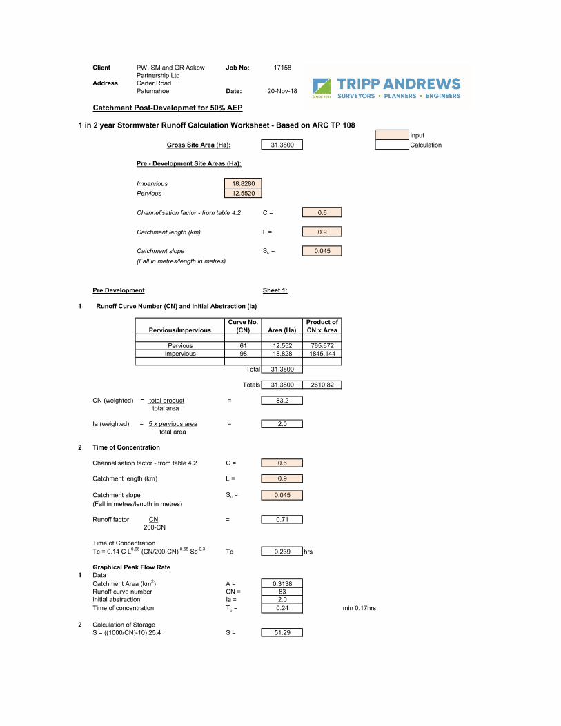
1 in 2 year Stormwater Runoff Calculation Worksheet - Based on ARC TP 108Input
31.3800 Calculation
Impervious 18.8280Pervious 12.5520
Channelisation factor - from table 4.2 C = 0.6
Catchment length (km) L = 0.9
Catchment slope Sc = 0.045(Fall in metres/length in metres)
Pre Development Sheet 1:
1 Runoff Curve Number (CN) and Initial Abstraction (Ia)
Pervious/ImperviousCurve No.
(CN) Area (Ha)Product of CN x Area
Pervious 61 12.552 765.672Impervious 98 18.828 1845.144
Total 31.3800
Totals 31.3800 2610.82
CN (weighted) = total product = 83.2 total area
Ia (weighted) = 5 x pervious area = 2.0 total area
2 Time of Concentration
Channelisation factor - from table 4.2 C = 0.6
Catchment length (km) L = 0.9
Catchment slope Sc = 0.045(Fall in metres/length in metres)
Runoff factor CN = 0.71 200-CN
Time of ConcentrationTc = 0.14 C L0.66 (CN/200-CN)-0.55 Sc-0.3 Tc 0.239 hrs
Graphical Peak Flow Rate1 Data
Catchment Area (km2) A = 0.3138Runoff curve number CN = 83Initial abstraction Ia = 2.0Time of concentration Tc = 0.24 min 0.17hrs
2 Calculation of StorageS = ((1000/CN)-10) 25.4 S = 51.29
Gross Site Area (Ha):
Pre - Development Site Areas (Ha):
PW, SM and GR Askew Partnership Ltd

3 Average recurrence interval (ARI) 1 in 24 24hr rainfall depth, P24(mm) (from TP 108) 197.2 (mm) Interperlated from TP108 Map + CC5 Compute c* = P24-(2 x Ia)/(P24 - 2 x Ia) +2 x S 0.656 Specific peak flow rate q* (from figure 6.1) 0.1307 Peak flow rate, qp = q* x A x P24 8.029 (m3/s)8 Runoff Depth, Q24 = (P24 - Ia)2/((P24-Ia) + S) 154.58 (mm)9 Runoff volume, V24 = 1000 x Q24 A 48508.29 (m3)

Client Job No: 17158
Address Carter RoadPatumahoe Date: 20-Nov-18
Catchement Pre-Developmet for 1% AEP
1 in 100 year Stormwater Runoff Calculation Worksheet - Based on ARC TP 108Input
31.3800 Calculation
Impervious 3.1380 10/90 SplitPervious 28.2420
Channelisation factor - from table 4.2 C = 0.8
Catchment length (km) L = 0.9
Catchment slope Sc = 0.045(Fall in metres/length in metres)
Pre Development Sheet 1:
1 Runoff Curve Number (CN) and Initial Abstraction (Ia)
Pervious/ImperviousCurve No.
(CN) Area (Ha)Product of CN x Area
Pervious 61 28.242 1722.762Impervious 98 3.138 307.524
Total 31.3800
Totals 31.3800 2030.29
CN (weighted) = total product = 64.7 total area
Ia (weighted) = 5 x pervious area = 4.5 total area
2 Time of Concentration
Channelisation factor - from table 4.2 C = 0.8
Catchment length (km) L = 0.9
Catchment slope Sc = 0.045(Fall in metres/length in metres)
Runoff factor CN = 0.48200-CN
Time of ConcentrationTc = 0.14 C L0.66 (CN/200-CN)-0.55 Sc-0.3 Tc 0.397 hrs
Graphical Peak Flow Rate1 Data
Catchment Area (km2) A = 0.3138Runoff curve number CN = 65Initial abstraction Ia = 4.5Time of concentration Tc = 0.40 min 0.17hrs
2 Calculation of StorageS = ((1000/CN)-10) 25.4 S = 138.58
Gross Site Area (Ha):
Pre - Development Site Areas (Ha):
PW, SM and GR Askew Partnership Ltd

3 Average recurrence interval (ARI) 1 in 1004 24hr rainfall depth, P24(mm) (from TP 108) 169 (mm) Interperlated from TP108 Map5 Compute c* = P24-(2 x Ia)/(P24 - 2 x Ia) +2 x S 0.376 Specific peak flow rate q* (from figure 6.1) 0.0777 Peak flow rate, qp = q* x A x P24 4.101 (m3/s)8 Runoff Depth, Q24 = (P24 - Ia)2/((P24-Ia) + S) 89.28 (mm)9 Runoff volume, V24 = 1000 x Q24 A 28017.27 (m3)
0.000.000.00

Client Job No: 17158
Address Carter RoadPatumahoe Date: 20-Nov-18
Catchment Post-Developmet for 1% AEP
1 in 100 year Stormwater Runoff Calculation Worksheet - Based on ARC TP 108Input
31.3800 Calculation
Impervious 18.8280Pervious 12.5520
Channelisation factor - from table 4.2 C = 0.6
Catchment length (km) L = 0.9
Catchment slope Sc = 0.045(Fall in metres/length in metres)
Pre Development Sheet 1:
1 Runoff Curve Number (CN) and Initial Abstraction (Ia)
Pervious/ImperviousCurve No.
(CN) Area (Ha)Product of CN x Area
Pervious 61 12.552 765.672Impervious 98 18.828 1845.144
Total 31.3800
Totals 31.3800 2610.82
CN (weighted) = total product = 83.2 total area
Ia (weighted) = 5 x pervious area = 2.0 total area
2 Time of Concentration
Channelisation factor - from table 4.2 C = 0.6
Catchment length (km) L = 0.9
Catchment slope Sc = 0.045(Fall in metres/length in metres)
Runoff factor CN = 0.71 200-CN
Time of ConcentrationTc = 0.14 C L0.66 (CN/200-CN)-0.55 Sc-0.3 Tc 0.239 hrs
Graphical Peak Flow Rate1 Data
Catchment Area (km2) A = 0.3138Runoff curve number CN = 83Initial abstraction Ia = 2.0Time of concentration Tc = 0.24 min 0.17hrs
2 Calculation of StorageS = ((1000/CN)-10) 25.4 S = 51.29
Gross Site Area (Ha):
Pre - Development Site Areas (Ha):
PW, SM and GR Askew Partnership Ltd

3 Average recurrence interval (ARI) 1 in 1004 24hr rainfall depth, P24(mm) (from TP 108) 197.2 (mm) Interperlated from TP108 Map + CC5 Compute c* = P24-(2 x Ia)/(P24 - 2 x Ia) +2 x S 0.656 Specific peak flow rate q* (from figure 6.1) 0.1307 Peak flow rate, qp = q* x A x P24 8.029 (m3/s)8 Runoff Depth, Q24 = (P24 - Ia)2/((P24-Ia) + S) 154.58 (mm)9 Runoff volume, V24 = 1000 x Q24 A 48508.29 (m3)

Client Job No: 17158
Address Carter RoadPatumahoe Date: 20-Nov-18
Pipe Catchment 1
1 in 10 year Stormwater Runoff Calculation Worksheet - Based on ARC TP 108Input
20.4600 Calculation
Impervious 12.2760Pervious 8.1840
Channelisation factor - from table 4.2 C = 0.6
Catchment length (km) L = 0.9
Catchment slope Sc = 0.045(Fall in metres/length in metres)
Pre Development Sheet 1:
1 Runoff Curve Number (CN) and Initial Abstraction (Ia)
Pervious/ImperviousCurve No.
(CN) Area (Ha)Product of CN x Area
Pervious 61 8.184 499.224Impervious 98 12.276 1203.048
Total 20.4600
Totals 20.4600 1702.27
CN (weighted) = total product = 83.2 total area
Ia (weighted) = 5 x pervious area = 2.0 total area
2 Time of Concentration
Channelisation factor - from table 4.2 C = 0.6
Catchment length (km) L = 0.9
Catchment slope Sc = 0.045(Fall in metres/length in metres)
Runoff factor CN = 0.71200-CN
Time of ConcentrationTc = 0.14 C L0.66 (CN/200-CN)-0.55 Sc-0.3 Tc 0.239 hrs
Graphical Peak Flow Rate1 Data
Catchment Area (km2) A = 0.2046Runoff curve number CN = 83Initial abstraction Ia = 2.0Time of concentration Tc = 0.24 min 0.17hrs
2 Calculation of StorageS = ((1000/CN)-10) 25.4 S = 51.29
Gross Site Area (Ha):
Pre - Development Site Areas (Ha):
PW, SM and GR Askew Partnership Ltd

3 Average recurrence interval (ARI) 1 in 104 24hr rainfall depth, P24(mm) (from TP 108) 127.92 (mm) Interperlated from TP108 Map + CC5 Compute c* = P24-(2 x Ia)/(P24 - 2 x Ia) +2 x S 0.556 Specific peak flow rate q* (from figure 6.1) 0.1187 Peak flow rate, qp = q* x A x P24 3.081 (m3/s)8 Runoff Depth, Q24 = (P24 - Ia)2/((P24-Ia) + S) 89.48 (mm)9 Runoff volume, V24 = 1000 x Q24 A 18306.72 (m3)

Client Job No: 17158
Address Carter RoadPatumahoe Date: 20-Nov-18
1200mm Pipe Size Calculation Worksheet - Based on Mannings Input
Channel dimensions Calculation
Bw Pipe Radii 1.2 m
n Mannings roughness 0.011
S Slope 0.0080
A Flow Area 1.1304 m2
Wetted Perimeter 3.768 m
R Hydraulic Radius 0.3 m
Q Flowrate Q = (A*(R^.67)*(S^.5))/n)
4.103 m3/s
v Velocity V=Q/A
3.63 m/s
PW, SM and GR Askew Partnership Ltd
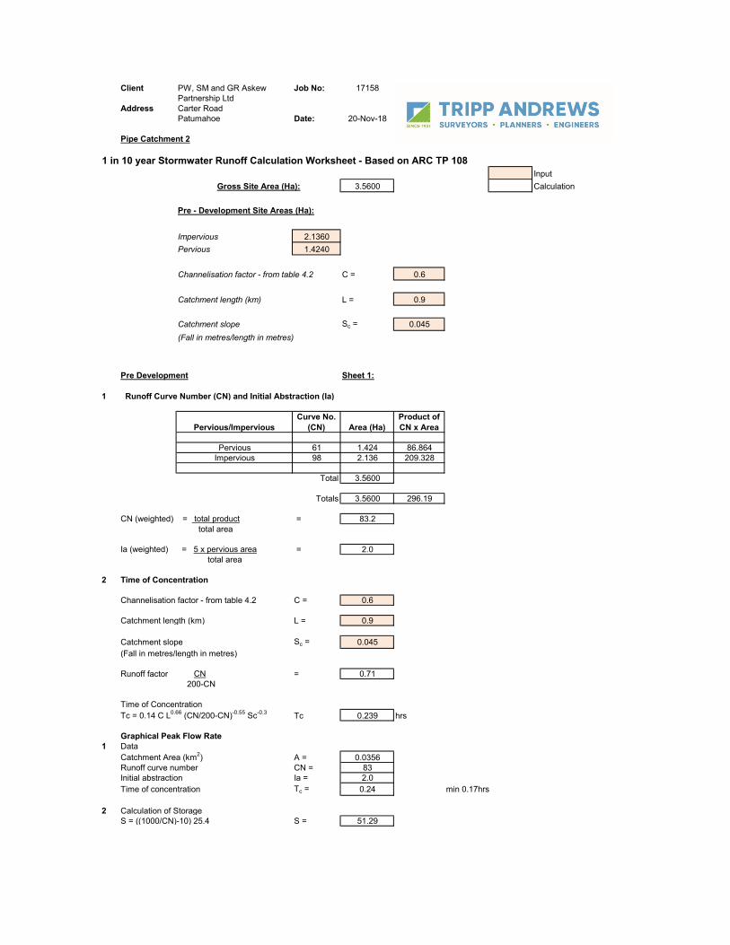
Client Job No: 17158
Address Carter RoadPatumahoe Date: 20-Nov-18
Pipe Catchment 2
1 in 10 year Stormwater Runoff Calculation Worksheet - Based on ARC TP 108Input
3.5600 Calculation
Impervious 2.1360Pervious 1.4240
Channelisation factor - from table 4.2 C = 0.6
Catchment length (km) L = 0.9
Catchment slope Sc = 0.045(Fall in metres/length in metres)
Pre Development Sheet 1:
1 Runoff Curve Number (CN) and Initial Abstraction (Ia)
Pervious/ImperviousCurve No.
(CN) Area (Ha)Product of CN x Area
Pervious 61 1.424 86.864Impervious 98 2.136 209.328
Total 3.5600
Totals 3.5600 296.19
CN (weighted) = total product = 83.2 total area
Ia (weighted) = 5 x pervious area = 2.0 total area
2 Time of Concentration
Channelisation factor - from table 4.2 C = 0.6
Catchment length (km) L = 0.9
Catchment slope Sc = 0.045(Fall in metres/length in metres)
Runoff factor CN = 0.71 200-CN
Time of ConcentrationTc = 0.14 C L0.66 (CN/200-CN)-0.55 Sc-0.3 Tc 0.239 hrs
Graphical Peak Flow Rate1 Data
Catchment Area (km2) A = 0.0356Runoff curve number CN = 83Initial abstraction Ia = 2.0Time of concentration Tc = 0.24 min 0.17hrs
2 Calculation of StorageS = ((1000/CN)-10) 25.4 S = 51.29
Gross Site Area (Ha):
Pre - Development Site Areas (Ha):
PW, SM and GR Askew Partnership Ltd

3 Average recurrence interval (ARI) 1 in 104 24hr rainfall depth, P24(mm) (from TP 108) 127.92 (mm) Interperlated from TP108 Map + CC5 Compute c* = P24-(2 x Ia)/(P24 - 2 x Ia) +2 x S 0.556 Specific peak flow rate q* (from figure 6.1) 0.1187 Peak flow rate, qp = q* x A x P24 0.536 (m3/s)8 Runoff Depth, Q24 = (P24 - Ia)2/((P24-Ia) + S) 89.48 (mm)9 Runoff volume, V24 = 1000 x Q24 A 3185.33 (m3)

Client Job No: 17158
Address Carter RoadPatumahoe Date: 20-Nov-18
600mm Pipe Size Calculation Worksheet - Based on Mannings Input
Channel dimensions Calculation
Bw Pipe Radii 0.6 m
n Mannings roughness 0.011
S Slope 0.0080
A Flow Area 0.2826 m2
Wetted Perimeter 1.884 m
R Hydraulic Radius 0.15 m
Q Flowrate Q = (A*(R^.67)*(S^.5))/n)
0.645 m3/s
v Velocity V=Q/A
2.28 m/s
PW, SM and GR Askew Partnership Ltd

Project: PATU Simulation Run: Run 1
Start of Run: 01Jan2000, 00:00 Basin Model: Basin 1End of Run: 02Jan2000, 00:00 Meteorologic Model: Met 1Compute Time:04Dec2018, 09:00:11 Control Specifications:Control 1
HydrologicElement
Drainage Area(KM2)
Peak Discharge(M3/S)
Time of Peak Volume(1000 M3)
Subbasin-2 0.27325.6 01Jan2000, 12:1034.8
Subbasin-1 0.04000.8 01Jan2000, 12:105.1
Sink-1 0.31326.4 01Jan2000, 12:1039.9

Client Job No: 17158
Address Carter RoadPatumahoe Date: 20-Nov-18
WETLAND DEIGN Input
31.3800 Calculation
Impervious 0.0000 CN Value 61.00Pervious 31.3800 ToC 0.42 Hours
Impervious 18.8280 CN Value 74.40Pervious 12.5520 ToC 0.27 Hours
Storm IntensitiesRainfall 24 Hours Climate Change factor
90th Percentile 25 mm -95th Percentile 34 mm -50% AEP 69 mm 75.2110% AEP 113 mm 127.921% AEP 170 mm 197.20
Hydrological CalculationsPWV 2234Forebay 335.1Detetnion Volume for Stream Protection50% AEP pre-development flow 0.89850% AEP post-development flow 2.332250% AEP runnoff volume difference 7081 6428 1350910% AEP pre-development flow 2.07610% AEP post-development flow 4.69410% AEP runnoff volume difference 13000 15000 280001% AEP pre-development flow 4.1361% AEP post-development flow 8.0291% AEP runnoff volume difference 20000 28000 48000
Permanatl Water Level AreaPWV 2234Weltand depth Co-eff 1.5
744.666667
Gross Site Area (Ha):
Pre - Development Site Areas (Ha):
PW, SM and GR Askew Partnership Ltd
Post - Development Site Areas (Ha):

Elevation storage claclulationsWL 0 0mWL 50% AEP 1.01mWL 10% AEP 1.63mWL 1% AEP 2.3mOverflow 2.6m
Outlet levels RL50% AEP 0m 61.810% AEP 1.01 62.811% AEP 1.63 64.44Overflow Weir Height 2.30 66.74Embankmant Height 2.60 69.34

TRIPP ANDREWS SURVEYORS LTD
20

27
TRIPP ANDREWS SURVEYORS LTD
Appendix C: Appendix C:
- Safety in Design Register

Safety in Design Register

SAFETY IN DESIGN – Carter Road, Patumahoe Proposed Private plan Change
Design Risk Assessment Register Author (Role): JM -
Approved By: AM -
Job No: 17158
Date: 5/10/20
Project Name: Patumahoe Plan Change Revision: 0 Stage of Design / Project: 90% Review - Prelim Design
Key; Notes: Hazards considered are those that are project / site specific, non-standard / bespoke designs,
special process, high hazard risks (e.g. non ‘business as usual’ hazards) that have been identified 1) Negligible 2) Minor 3) Serious 4) Extensive 5) Catastrophic
1) Rare 2) Unlikley 3) Possible 4) Likely 5) Almost Certain
L) Low M) Moderate H) High E) Extreme at the time of the review(s). Other risks will continue to a
Risk Owner Action Required
Likelihood
Level of Risk: Consequence
DESIGN RISK Risk Matrix
Ref
Hazard
(Guideword)
Issue
C
L
R R
MITIGATION MEASURES Mitigated Risk & Resolution Risk Owner
Proposed Measure (at time of SiD meeting)
(1 Eliminate, 2 Substitute, 3 Reduce, 4 Control)
C
L
R R
Design
Status
Date
1 Construction
1.01 Interfaces External to the Project
Drainage at tie-ins to existing Network, risk of Overflows 4 4 H
Contractor Minimise number of tie ins, identify simpler alternative construction methods to minimise worktime. (eg install pies prior to conecetion) 4 3 M
Open 28/01/20
1.02 Egress / Access Unsafe worksite, due to flooding, water. 5 4 E Contractor Investigation and knowledge of ground conditions/water levels. Consider time of year. 5 1 M
Open 28/01/20
1.03 Movement Direction Ground stability/haul roads for heavy plant and lifting operations. Rolling over. 5 4 E Contractor Detailed assessment of ground conditions, ground improvement extent large enough. 5 2 M
Open 28/01/20
1.04 Load / Force / Energy Unsafe temporary access to trenches and pits. 5 4 E Contractor Review existing ground conditions. Design and methodolgy, maintain design standards, trench shields. 3 2 M
Open 28/01/20
1.05 Traffic Existing connection for site water to be connection on Carter
Road
3
5
H Contractor Design considering construction methodologies and materialswhich minimize
time oin traffic management areas, ie Electro fusion. Ensure TMP is upto date.
3
3
M
Open
28/01/20
1.06 Ergonomics Working around Trenches, potential for slipping in. 4 2 M Contractor Methodology during Pipe and manhole installation. 4 1 L Open 28/01/20
1.07 Heights / Depths Deep manholes, height, confined spaces, gases, groundwater. 5 4 E Contractor Review locations and numbers required. Alternative methods for maintenance. 4 3 M Open 28/01/20
1.08 Toxicity / Safety Handling of sewerage whilst working on wastewater lines. 2 3 M Contractor Review of final inoculation and training prior to construction. 2 3 M
Open 28/01/20
1.09 Toxicity / Safety Handling of heavy items. 3 3 M Contractor Detailing of large components. 2 2 L Open 28/01/20
1.10 Utilities/Services Injury resulting from relocating services. 4 3 M Contractor Try to avoid services. Involve service providers when designing relocations/protectrion. 4 2 M
Open 28/01/20
1.11 Interfaces External to the Project Traffic hazards on live roads. 3 3 M Contractor Reinstatement to be undertaken under traffic managment 3 2 M
Open 28/01/20
1.12 Dam safety Construction of the wall/bund holding in the 20,000m3 volume at a 1% AEP
5 4 E
Designer Correct procedure in place for for Dam safety and working in accordance to the geotechnical requirements
5 1 M
Open 28/01/20
1.13
2 Operation/Maintenance 2.01 Heights / Depths Confined spaces, access and egress to deep, long structures for
maintenance. 5 3 H
Local Authority Design to consider ease of ventilation, detailing of access/egress points. 5 1 M
Open 28/01/20
2.02 Interfaces External to the Project Public access into drainage structures. Drowning, injury. 5 3 H Local Authority Design to prevent unauthorised access. Fences, grilles etc. 5 1 M
Open 28/01/20
2.05 Interfaces External to the Project Repair of Water Assets next to live traffic lanes. 3 5 H Local Authority Use robust materials, provide clearances to give safe access. 3 3 M
Open 28/01/20
2.06 Interfaces External to the Project Maintenance of Wastewater Assets . Risk of Access issues 3 3 M Local Authority
Diversion design to ensure access to all parts of wastewater network through the site. 3 2 M
Open 28/01/20
2.07 Interfaces External to the Project
New vehicle accessways maintenance on Patumahoe Road 3 3 M Local Authority Design materials, reduce maintenance requirements. 3 2 M
Open 28/01/20
2.08 Interfaces External to the Project Risk of pedestrians on vehicle accessway, traffic strike. 5 3 H Local Authority Design appropriate accesses. Design to prevent access where this is not wanted. 5 2 M
Open 28/01/20
2.09 Site Caused Environment Landscape maintenance, risk to personnel. 3 3 M Local Authority Choose appropriate planting and offsets. 3 2 M
Open 28/01/20