stormwater management manual - placer county, ca
TRANSCRIPT

PLACER COUNTY FLOOD CONTROL AND WATER CONSERVATION DISTRICT
STORMWATERMANAGEMENT
MANUAL
SEPTEMBER 1, 1990
11444 B AVENUE AUBURN. CA.95603

PLACER COUNTY FLOOD CONTROL AND WATER CONSERVATION DISTRICT STORMWATER MANAGEMENT MANUAL FEBRUARY 1994
TABLE OF CONTENTS
Page I. INTRODUCTION Purpose and Scope...... ............ ............ ........... ............ ............ ............ ........... ............ ............I-1 Overview - Organization and Use of Manual ............ ............ ............ ........... ............ ............I-1 Description of Region ............ ............ ........... ............ ............ ............ ........... ............ ............I-2 Flood Control District ............ ............ ........... ............ ............ ............ ........... ............ ............I-3 Acknowledgments ...... ............ ............ ........... ............ ............ ............ ........... ............ ............I-3 II. GOALS AND POLICIES Goals . ............ ............ ............ ............ ........... ............ ............ ............ ........... ............ ............II-1 Principles and Concepts .......... ............ ........... ............ ............ ............ ........... ............ ............II-1 Policies ........... ............ ............ ............ ........... ............ ............ ............ ........... ............ ............II-2 III. MASTER PLANS Purpose........... ............ ............ ............ ........... ............ ............ ............ ........... ............ ............III-1 Policies ........... ............ ............ ............ ........... ............ ............ ............ ........... ............ ............III-1 Master Plan Elements. ............ ............ ........... ............ ............ ............ ........... ............ ............III-2 Approvals....... ............ ............ ............ ........... ............ ............ ............ ........... ............ ............III-4 Distribution and Coordination ............ ........... ............ ............ ............ ........... ............ ............III-4 IV. REGULATORY REQUIREMENTS Purpose and Scope...... ............ ............ ........... ............ ............ ............ ........... ............ ............IV-1 Basic Drainage Law Requirements ..... ........... ............ ............ ............ ........... ............ ............IV-1 General Plans . ............ ............ ............ ........... ............ ............ ............ ........... ............ ............IV-1 Subdivision Map Act.. ............ ............ ........... ............ ............ ............ ........... ............ ............IV-2 California Environmental Quality Act (CEQA)........... ............ ............ ........... ............ ............IV-2 Porter-Cologne Water Quality Control Act..... ............ ............ ............ ........... ............ ............IV-2 California Fish and Game Code........... ........... ............ ............ ............ ........... ............ ............IV-3 Section 404 of the National Clean Water Act . ............ ............ ............ ........... ............ ............IV-4 National Flood Insurance Program (NFIP) ..... ............ ............ ............ ........... ............ ............IV-4 Definitions...... ............ ............ ............ ........... ............ ............ ............ ........... ............ ............IV-5 V. HYDROLOGY ......... ............ ............ ........... ............ ............ ............ ........... ............ ............V-1 Purpose........... ............ ............ ............ ........... ............ ............ ............ ........... ............ ............V-1 General Principles and Policies............ ........... ............ ............ ............ ........... ............ ............V-1 Precipitation... ............ ............ ............ ........... ............ ............ ............ ........... ............ ............V-1 Infiltration and Other Losses... ............ ........... ............ ............ ............ ........... ............ ............V-4 Runoff Computation... ............ ............ ........... ............ ............ ............ ........... ............ ............V-7 V-A APPENDIX Precipitation Data ....... ............ ............ ........... ............ ............ ............ ........... ............ ............V-A-1
Version 3 1 February 1994

PLACER COUNTY FLOOD CONTROL AND WATER CONSERVATION DISTRICT STORMWATER MANAGEMENT MANUAL FEBRUARY 1994
TABLE OF CONTENTS (Continued)
Page
V-B APPENDIX Design Storm Procedures........ ............ ........... ............ ............ ............ ........... ............ ............V-B-1 VI. DRAINAGE SYSTEMS Purpose........... ............ ............ ............ ........... ............ ............ ............ ........... ............ ............VI-1 Principles and Policies ............ ............ ........... ............ ............ ............ ........... ............ ............VI-1 Streets and gutters....... ............ ............ ........... ............ ............ ............ ........... ............ ............VI-2 Underground Conduits ............ ............ ........................ ............ ............ ............ ........... ............VI-4 Culverts for Transverse Crossings....... ........... ............ ............ ............ ........... ............ ............VI-10 VI-A APPENDIX Federal Highway Administration Nomographs ........... ............ ............ ........... ............ ............VI-A-1 VII. STORAGE FACILITIES Introduction.... ............ ............ ............ ........... ............ ............ ............ ........... ............ ............VII-1 Concepts and Definitions ........ ............ ........... ............ ............ ............ ........... ............ ............VII-1 Principles and Policies ............ ............ ........... ............ ............ ............ ........... ............ ............VII-2 Hydrologic Evaluation ............ ............ ........... ............ ............ ............ ........... ............ ............VII-3 General Criteria .......... ............ ............ ........... ............ ............ ............ ........... ............ ............VII-5 Alternative On-site Storage..... ............ ........... ............ ............ ............ ........... ............ ............VII-11 Documentation............ ............ ............ ........... ............ ............ ............ ........... ............ ............VII-13 VIII. STREAMS AND CHANNELS Definitions...... ............ ............ ............ ........... ............ ............ ............ ........... ............ ............VIII-1 Policies ........... ............ ............ ............ ........... ............ ............ ............ ........... ............ ............VIII-1 Criteria ........... ............ ............ ............ ........... ............ ............ ............ ........... ............ ............VIII-2 IX. EROSION AND SEDIMENTATION Purpose........... ............ ............ ............ ........... ............ ............ ............ ........... ............ ............IX-1 Erosion ........... ............ ............ ............ ........... ............ ............ ............ ........... ............ ............IX-1 Sedimentation and Sediment Retention Structures ...... ............ ............ ........... ............ ............IX-10 X. GLOSSARY XI. ADDENDUM I (Additions and revisions to respective portions) XII. PROJECT SUBMITTAL REQUIREMENTS
Version 3 2 February 1994

PLACER COUNTY FLOOD CONTROL AND WATER CONSERVATION DISTRICT STORMWATER MANAGEMENT MANUAL FEBRUARY 1994
TABLES Table ........... ............ ............ ............ ............ ........... ............ ............ ............ ........... ............ ............Page 5-1 Point Gage and Area Spatial Intensity Relationships .. ............ ............ ........... ............ ............V-3 5-2 Snowmelt Rates ......... ............ ............ ........... ............ ............ ............ ........... ............ ............V-4 5-3 Constant Infiltration Rates for Hydrologic Soil-Cover Complexes ...... ........... ............ ............V-6 5-4 Snow-Covered Areas.. ............ ............ ........... ............ ............ ............ ........... ............ ............V-8 5-5 Roughness Parameters for Overland Flow...... ............ ............ ............ ........... ............ ............V-10 5-6 Coefficients for Unit Peak Discharge .. ........... ............ ............ ............ ........... ............ ............V-13 5-A-1 Depth-Duration Data .. ............ ............ ........... ............ ............ ............ ........... ............ ............V-A-2 5-A-3 Intensity vs. Duration . ............ ............ ........... ............ ............ ............ ........... ............ ............V-A-10 6-1 Allowable Street Encroachments......... ........... ............ ............ ............ ........... ............ ............VI-3 6-2 Manhole Spacing........ ............ ............ ........... ............ ............ ............ ........... ............ ............VI-5 6-3 Manning n Values for Design of Drainage Conduits... ............ ............ ........... ............ ............VI-6 6-4 Entrance Loss Coefficients...... ............ ........... ............ ............ ............ ........... ............ ............VI-7 6-5 Contraction Loss Coefficients. ............ ........... ............ ............ ............ ........... ............ ............VI-8 6-6 Entrance Loss Coefficients...... ............ ........... ............ ............ ............ ........... ............ ............VI-12 8-1 Manning n for Streams and Channels.. ........... ............ ............ ............ ........... ............ ............VIII-3 8-2 Permissible Velocities for Earth-Lined Channels ........ ............ ............ ........... ............ ............VIII-7 8-3 Permissible Velocities for Well Maintained Grass Channels... ............ ........... ............ ............VIII-10 8-4 Flow Retardance Classes for Grassed Channels .......... ............ ............ ........... ............ ............VIII-11 8-5 Roughness Coefficients for Lined Channels ... ............ ............ ............ ........... ............ ............VIII-12 8-6 Permissible Side Slopes for Lined Channels... ............ ............ ............ ........... ............ ............VIII-12 9-1 Settling Velocities of Selected Particles .......... ............ ............ ............ ........... ............ ............IX-12
Version 3 3 February 1994

PLACER COUNTY FLOOD CONTROL AND WATER CONSERVATION DISTRICT STORMWATER MANAGEMENT MANUAL FEBRUARY 1994
FIGURES Figure Page 5-1 Overland Flow Response Time............ ........... ............ ............ ............ ........... ............ ............V-11 5-2 V Channel Response Time...... ............ ........... ............ ............ ............ ........... ............ ............V-12 5-3A Unit Peak Flow vs. Elevation, 10-Year .......... ............ ............ ............ ........... ............ ............V-14 5-3B Unit Peak Flow vs. Elevation, 25-Year .......... ............ ............ ............ ........... ............ ............V-15 5-3C Unit Peak Flow vs. Elevation, 100-Year ........ ............ ............ ............ ........... ............ ............V-16 5-4 Fi vs. I, Elevation ........ ............ ............ ........... ............ ............ ............ ........... ............ ............V-17 5-5 Small Watershed Peak Flow Worksheet ......... ............ ............ ............ ........... ............ ............V-18 6-1 Rectangular Manhole Loss Coefficients.......... ............ ............ ............ ........... ............ ............VI-8 6-2 Definition Sketch for Junction Losses. ........... ............ ............ ............ ........... ............ ............VI-10 6-3 Definition Sketch for Culvert with Inlet Control ......... ............ ............ ........... ............ ............VI-11 7-1 Objective Outflows for Mitigation....... ........... ............ ............ ............ ........... ............ ............VII-4 7-2 Dam Safety Jurisdiction .......... ............ ........... ............ ............ ............ ........... ............ ............VII-7 8-1 Natural Channel Components . ............ ........... ............ ............ ............ ........... ............ ............VIII-5 8-2 Manning's n and Retardance for Grass-Lined Channels........... ............ ........... ............ ............VIII-8 8-3 Values of n for Riprap Lined Channels, d50 size vs. Depth of Flow.... ........... ............ ............VIII-14 8-4 Velocity vs. Depth of Flow ..... ............ ........... ............ ............ ............ ........... ............ ............VIII-13 9-1 Manning's for Riprap-Lined Channels ........... ............ ............ ............ ........... ............ ............IX-4 9-2 Median Riprap Diameter for Straight Trapezoided Channels .. ............ ........... ............ ............IX-5 9-3 Median Riprap Diameter for Straight Triangular Channels ..... ............ ........... ............ ............IX-6 9-4 Riprap Size Correction Factor for Flow in Channel Bends ...... ............ ........... ............ ............IX-7 9-5 Maximum Riprap Side Slope with Respect for Riprap Size .... ............ ........... ............ ............IX-7 9-6 Reservoir Trap Efficiencies..... ............ ........... ............ ............ ............ ........... ............ ............IX-12 9-7 Sediment Delivery Ratios........ ............ ........... ............ ............ ............ ........... ............ ............IX-13
Version 3 4 February 1994

PLACER COUNTY FLOOD CONTROL AND WATER CONSERVATION DISTRICT STORMWATER MANAGEMENT MANUAL SEPTEMBER 1. 1990
I. INTRODUCTION A. Purpose and Scope
Increasing growth in Placer County has lead to increasing problems associated with stormwater runoff.
Flooding is a primary problem. Much of the growth has occurred adjacent to streams which drain the region, resulting in significant damages to property, losses from the disruption of commercial activities, and potential loss of life when the streams overflow. Further, development in the watersheds of these streams affects both the frequency and duration of damaging floods. Other problems connected with stormwater runoff include erosion, sedimentation, degradation of water quality and losses of environmental resources.
Every development project within the county has some effect on the stormwater runoff both on-site (within the boundaries of the project) and off-site (downstream areas outside the boundaries of the project). Furthermore, although project-specific effects may be small, the cumulative impact of several similar projects may be-significant. Local government is responding with a greater commitment to alleviate current problems and plan for growth to minimize future ones. This manual stems from that commitment.
The purpose of this manual is to provide consistent, specific guidance and requirements for stormwater management, including regulation of the development process, to achieve stormwater management objectives. The manual is intentionally an evolutionary document. Its initial focus is on flooding problems. Over time the scope will expand to include more on sedimentation, erosion, water quality, and environmental effects. It will also be updated periodically to reflect new information and technology.
B. Overview - Organization andUse of Manual
This manual presents policy, guidelines, and specific criteria for the development and management of natural resources, facilities and infrastructure for stormwater management. Policy is presented to help clarify specific criteria and to aid in their interpretation or application. General goals and policies are presented in Chapter II and specific policies are stated in appropriate chapters. The chapters of the manual are organized as follows: I. Introduction - States the purpose of the manual, provides an overview and a brief description of the region, and briefly describes the Placer County Flood Control District.
PLACER COUNTY FLOOD CONTROL AND WATER CONSERVATION DISTRICT STORMWATER MANAGEMENT MANUAL SEPTEMBER 1, 1990
Since this manual will be periodically revised, the table of contents contains information on the current version of each chapter, and page headers indicate a date as well.
II. Policy - States general goals, principles and policies.
III. Master Plan - Describes the role of the master plan in stormwater management.
IV. Regulatory Requirements - Identifies the various regulatory agencies which have jurisdiction over aspects of stormwater management. V. Hydrology - Provides policies, guidelines, and criteria for determining flows and volumes of runoff. VI. Drainage Systems - Provides policies, guidelines and criteria for the design of drainage systems and related facilities, including streets and gutters, pipes and culverts. VII. Storage - Provides policies, guidelines and criteria for the planning and design of storage facilities. VIII. Streams and Channels - Provides policies, guidelines and criteria for planning, designing, and maintaining open channels, including both artificial and natural channels. IX. Erosion and Sedimentation - Provides policies, guidelines and criteria for addressing erosion and sedimentation-concerns in the development of drainage systems. Supplements, including a glossary, are provided following the chapters identified above.
C. Description of Region
This manual applies primarily to the developing areas of Placer County which extend westward from Colfax to Sutter County. This western area contains most of the County's population and is rapidly growing.
Elevations in Western Placer County range from about 30 feet above mean sea level at the western boundary to about 3000 feet near Colfax. The topography ranges from nearly flat in the far western areas to rolling Sierra Foothills with moderate to steep slopes in the east.
The climate is characterized by a hot, dry summers and winters with moderate to heavy precipitation. Precipitation falls as rain resulting from extensive storms which originate in the Pacific Ocean. Normal annual precipitation varies with elevation and ranges from 19 inches to 42 inches.
Flood flows are generally confined to_well-defined
stream channels in the foothill portions of the region. Farther west, the flat landscape results in extensive overflow of flood waters into the adjacent
Page I-2

PLACER COUNTY FLOOD CONTROL AND WATER CONSERVATION DISTRICT STORMWATER MANAGEMENT MANUAL SEPTEMBER 1, 1990
floodplains. In both areas, the channels are often dense with riparian vegetation.
Vacant, undeveloped land is typically covered with annual grasses with oak and brush woodlands occurring in many locations. Cottonwoods, willows, oaks and dense brush occur in riparian areas. Pasture and orchards are the predominant agricultural developments. Soils in the watershed are generally shallow and permit little infiltration, especially when previous precipitation has saturated the soil mantle.
The objectives of the Flood Control District for reducing the effects of flooding are: 1. Maintain major drainage facilities,
primarily stream channels, and detention and retention basins.
2. Provide technical support to local
governments, as exemplified by this manual.
3. Perform regional drainage studies,
including master drainage plans, and implement the regional projects and programs delineated therein.
Provide flood potential advisories to local governments. Gather information and data on flooding events.
D. Flood Control District The Placer County Flood Control and Water Conservation District was formed by legislative resolution on Senate Bill 1312 (Johnson), effective August 23, 1984. The Flood Control District is supported through a cooperative effort by the County and the Cities of Auburn, Colfax, Lincoln, Rocklin and Roseville and the Town of Loomis. District policies and activities are largely guided by the consensus of participating members. Other governmental agencies, particularly-the.Placer._Resource Conservation District and the Soil Conservation Service, have played instrumental roles in the formation and guidance of the District.
6. Coordinate flood reduction activities with adjacent jurisdictions.
E. Acknowledgments
This manual was developed with contributions from many sources. Dave Dawdy, hydrologic consultant, provided the first draft. Thereafter, a subcommittee of the Flood Control District Technical Advisory Committee was generally responsible for producing the manual, and subsequent drafts were prepared by the District Staff. other contributors included general members of the Technical Advisory
5.
4.

PLACER COUNTY FLOOD CONTROL AND WATER CONSERVATION DISTRICT STORMWATER MANAGEMENT MANUAL SEPTEMBER 1. 1990 Committee, local agencies, the Stream Management Task Force, and reviewers of the various drafts.
Page I-4

PLACER COUNTY FLOOD CONTROL AND WATER CONSERVATION DISTRICT STORMWATER MANAGEMENT PLAN SEPTEMBER 1, 1990 II. GOALS AND POLICIES This chapter states the overall goals and general principles and policies of the Flood Control District regarding stormwater management. These goals, principles and policies were developed in cooperation with City and County staff and elected representatives, and representatives of the private engineering and development communities. The goals, principles and policies presented in this chapter provide direction for stormwater management strategies and practices. They are implemented, in turn, by technical criteria and data in the manual. A. Goals
1. Provide protection from periodic inundation which could result in loss of life and property.
2. Protect and enhance natural
resources belonging to the stream environment.
3. Prevent significant erosion and
adverse effects on water quality.
4. Provide a regional approach to stormwater management which is both internally consistent and consistent with other community goals and plans.
5. Achieve maximum use of
resources through multiple compatible uses.
6. Assure orderly growth and
development and minimize its adverse effects.
B. Principles and Concepts The following principles are broad, basic concepts which underlie policies and related criteria. 1. The provision of adequate stormwater management facilities and programs is necessary to preserve and promote general health, welfare, and economic well-being. 2. Future problems can be minimized or avoided if jurisdictions in a watershed agree to common standards, methodologies, and criteria pertaining to control of runoff and land development. 3. Every parcel of land is part of and contributes runoff to that of a larger watershed. This cumulative characteristic of runoff makes it advisable to formulate strategies that are coordinated, integrated, and balanced on a regional level if effective results are to be achieved.
Page II-1

PLACER COUNTY FLOOD CONTROL AND WATER CONSERVATION DISTRICT STORMWATER MANAGEMENT PLAN SEPTEMBER 1, 1990 4. Both the public and individual property owners share responsibility for stormwater management. 5. Effective stormwater management requires a land use commitment. Stormwater management competes for space with other land uses. If adequate provision is not made in a land use plan, stormwater run-off may conflict with other land uses and result in water damages and impair or disrupt the functioning of other systems. 6. A stormwater management strategy must consider multiple means of accomplishing its objectives. In general, there is not a single, all- encompassing method or design: every site or situation presents a unique mix of scale, resources, land use constraints, and environmental setting. 7. It is essential to distinguish between levels of objectives in drainage systems. These two levels are commonly referred to as the minor function and the major function. The minor function is usually to limit disruption and to minimize inconveniences resulting from more frequently occurring, less significant storms. Storm drain systems consisting of underground pipes are commonly used to provide the minor function. The major function is to prevent or minimize property damage, injury, and
loss of life during infrequent, major storms. 8. The financing of stormwater management systems is fundamentally the responsibility of the affected property owners -- both the person directly affected by the water and the person from whose land the water flows. However, there is a public interest involved because of the potential demand for disaster relief. 9. Floodwater management, treatment of runoff for water quality protection, and protection of riparian environmental resources are not necessarily conflicting and may be complementary. 10. A program for collecting and analyzing basic data is essential in developing effective stormwater management strategies and monitoring their performance. In the long term, significant cost savings can also be realized by avoiding oversized systems. Further, monitoring may be a requirement for compliance with regulatory programs. 11. Flood preparedness, warning and response programs are important in reducing loss of life, injury, property damage, and disruption due to flooding. C. Policies
Page II-2

PLACER COUNTY FLOOD CONTROL AND WATER CONSERVATION DISTRICT STORMWATER MANAGEMENT PLAN SEPTEMBER 1, 1990 1. Design Criteria a. Storm drainage planning and design in Western Placer County shall adhere to the criteria presented in this manual. Governmental agencies and engineers shall utilize the manual in the planning of new facilities and in their reviews of proposed works by developers, private parties, and other governmental agencies, including the California Department of Transportation, other elements of the State Government and the Federal Government. However, none of the criteria or guidelines are intended to substitute for the sound application of fundamental engineering or scientific principles or to conflict with stated goals and policies. b. The design criteria in this manual shall be revised and updated as necessary to reflect advances in stormwater management concepts and technology. 2. Level of Protection a. The 100-year flood shall be the criterion for measures intended to minimize property damage, injury, and loss of life. 3. Transfer of Problems a. Improvements of any kind shall not transfer a problem from one location to
another except when the transfer is part of a regional solution to flood problems. b. Channel modifications which create problems downstream shall be avoided. Potential problems include erosion, downstream sediment deposition, increase of runoff peaks, and debris transport. c. Diversions from one watershed to another shall generally be avoided. The diversion of storm runoff from one watershed to another may introduce significant legal problems. d. All land development proposals shall be evaluated for their effects on runoff and flooding, both offsite and onsite. 4. Floodplain Management Floodplain management is an important component of overall stormwater management strategies. a. Local jurisdictions are encouraged to adopt and implement measures which will lessen the exposure of property and facilities to flood losses, improve the long-range land management and use of flood-prone areas, and inhibit, to the maximum extent feasible, incompatible development and encourage compatible uses in such areas. Compatible uses are those which do not reduce instream flood storage, create higher flood elevations, or adversely effect riparian or aquatic resources. Compatible uses can include
Page II-3
PLACER COUNTY FLOOD CONTROL AND WATER CONSERVATION DISTRICT STORMWATER MANAGEMENT PLAN SEPTEMBER 1, 1990 open space, parks and recreation, and agriculture. b. Floodplain designations should account for future development. c. Flood plains should be delineated along all significant streams in areas which are developing. These delineations should make full use of the Corps of Engineers Flood Plain Information Studies, U.S. Geological Survey Flood Plain Maps, and floodplain studies by private consulting engineers and engineers of the Federal Emergency Management Agency. d. Floodplain information will be reviewed and updated as necessary and appropriate to reflect changes due to urbanization, changed conditions, and new information, including the occurrences of extraordinary hydrologic events. e. Floodplain boundaries shall be shown on preliminary and final subdivision plats, and the area inundated should be indicated as a flow easement or dedicated in fee. This would encompass even the smaller streams which are often overlooked even though they may have a large flood damage potential. f. Information on floodplain elevations and boundaries shall be collected and stored in a central place by the
jurisdiction and made available to all planners, developers, and engineers. g. General and specific plans should require compatible uses in the 100-year floodplain and require easements to facilitate effective floodplain management. 5. Natural Streams a. Natural drainage ways shall be used for storm runoff whenever possible. The environmental value of natural channels is clear. Natural channels are also valuable in controlling storm runoff because vegetation and irregular sections and alignments of natural channels dissipate energy, thereby slowing the runoff. Furthermore, the floodplain typically provides temporary storage of floodwaters which attenuates flood peaks as they pass through the channel reach. b. Local jurisdictions shall not permit loss of storage in the 100- year floodplain of designated regional streams except when necessary to protect existing structures or improvements from flood damages or to provide for improvements which have greater overall public value. Changes shall be allowed in the floodplain in association with compatible uses so long as the changes involve no net loss of storage. For example, minor grading and earthworks could be permitted on broad
Page II-4

PLACER COUNTY FLOOD CONTROL AND WATER CONSERVATION DISTRICT STORMWATER MANAGEMENT PLAN SEPTEMBER 1, 1990 floodplains in order to develop parks and recreational facilities. c. Local jurisdictions shall not permit straightening, widening, or smoothing of designated regional stream channels except as necessary to protect existing structures or improvements from flood damages or to provide for improvements which have greater overall public value. However, changes in the channel which restore, improve or enhance the desirable flood control properties shall be allowed and are encouraged. d. The Flood Control District shall develop comprehensive plans and criteria for the maintenance of designated regional stream channels. In order to maintain their effectiveness, natural streams must be managed. Erosion, widening and meandering stream alignments are natural processes which may be accelerated by increased runoff due to development. Over time, selective improvements such as drop structures and bank protection may be required to help stabilize channels at specific locations to protect structures and public facilities. Vegetation may be used to help stabilize channels as well. Irrigation flows and runoff in the summertime can cause excessive growth of vegetation which must be removed, especially in smaller streams.
Sedimentation can also create localized problems. e. Local jurisdictions and individuals are encouraged to follow Flood Control District plans and criteria for the maintenance of designated regional stream channels. 6. Multipurpose Use Opportunities for multipurpose use of facilities to achieve drainage goals will be considered. The many competing demands placed upon water and funds suggest that a strategy for managing runoff be as multipurpose as practical. Stormwater management facilities can fulfill a number of other purposes, and facilities not designed primarily for stormwater management frequently can be designed to provide runoff management benefits; e.g., parks or golf courses can provide temporary storage of peak flows. The land areas required for controlling the 100-year or even 10-year flood are infrequently used. Given the scarcity of water, land and funding for facilities, it makes sense to consider multipurpose use. 7. Basin Master Plans a. Master plans will be prepared as soon as possible for each drainage basin.
Page II-5

PLACER COUNTY FLOOD CONTROL AND WATER CONSERVATION DISTRICT STORMWATER MANAGEMENT PLAN SEPTEMBER 1, 1990 b. Regional master plans will be prepared by the Flood Control District. c. Each municipality in Placer County is responsible for detailed master plans in its jurisdiction. The Flood Control District will coordinate the local plans to assure consistency with the regional plans. d. All individual land development proposals shall be reviewed for compatibility with master plans. e. Master plans shall be consistent with other elements of general plans. Drainage is an interrelated component of the total community infrastructure. General plan policies must be considered in order to be effective and avoid conflicts or impacts on other elements. 8. Flood Preparedness, Warnings, and Response Planning a. The Flood Control District shall assist local jurisdictions and the Placer County Office of Emergency Services in the preparation of flood warning and response plans. b. The Flood Control District shall assist local jurisdictions in the planning, implementation, and operation of flood warning systems. c. The Flood Control District shall provide advise and consultations to local
jurisdictions and the Placer County Office of Emergency Services in evaluating imminent or ongoing flood events. d. The Flood Control District shall develop, publicize, and provide guidelines for flood preparedness and response. e. Local governments are encouraged to develop community preparedness plans. These plans will make effective use of flood warnings in mobilizing community resources to prepare and adjust for flood conditions. 9. Water Quality a. The Flood Control District shall compile, evaluation and incorporate in this manual policies, criteria and guidelines for the planning and development of systems for the treatment of runoff to protect water quality. b. The Flood Control District shall provide a regional forum to facilitate and participate in the development of programs and plans to satisfy the requirements of the Federal Non-Point Discharge Elimination System (NPDES) permit. c. The Flood Control District will incorporate final rules and regulations when plans for nonpoint source management have been approved by the
Page II-6
PLACER COUNTY FLOOD CONTROL AND WATER CONSERVATION DISTRICT STORMWATER MANAGEMENT PLAN SEPTEMBER 1, 1990 EPA and California State Regional Water Quality Control Board. 10. Data Collection a. Flood damage data will be collected in a systematic and uniform manner. A systematic and uniform method of appraising direct and indirect damages assures comparability of data. b. A comprehensive program to collect data and analyze rainfall-runoff relationships shall be developed and maintained. c. The magnitude of computed and measured runoff peaks shall be tabulated for regional streams so that comparisons may be readily made between basins, erroneous (or at least differing) values may be identified, and the effects of development may be determined. d. The Flood Control District shall archive and maintain all pertinent data developed during the master plan process and make it available to all affected parties. This data would include maps, map overlays, reports, and hydrologic and hydraulics models. e. The Flood Control District shall acquire and actively maintain a Library which shall be available for use by all governmental units and practicing planners and engineers.
11. Adoption of Manual a. This Manual shall be adopted by all jurisdictions in the county. b. The review and adoption process for this Manual will include both public and private interests. c. This Manual will be the basis for all master drainage plans and the Flood Control District's review of all local drainage plans. d. The Flood Control District will present the Manual to all appropriate State and Federal Agencies for review. e. The Flood Control District will provide technical assistance to both public and private entities to increase local capabilities in drainage planning and design. f. Implementation of the Manual shall be supported and promoted by the staffs of participating jurisdictions. 12. Amendments a. Problems encountered in application of this manual shall be reviewed by the Flood Control District to determine whether it indicates a need for a new or different policy, practice, or procedure.
Page II-7

PLACER COUNTY FLOOD CONTROL AND WATER CONSERVATION DISTRICT STORMWATER MANAGEMENT PLAN SEPTEMBER 1, 1990 b. The Flood Control District's Technical Advisory Committee shall continually review needs and shall recommend changes as necessary in this Manual. c. Any person finding errors, misconceptions, or proposing improvements to this manual is requested to contact the Flood Control District Engineer. d. Amendments or additions to goals or policies in the Manual shall be approved by the District’s Policy Advisory Committee and Board of Directors. e. Amendments or additions to portions of the Manual other than goals or policies may be approved by the Director with the recommendation of the District’s Technical Advisory Committee.
Page II-8

PLACER COUNTY FLOOD CONTROL AND WATER CONSERVATION DISTRICT STORMWATER MANAGEMENT MANUAL SEPTEMBER 1. 1990
development policies and decisions are also identified. For example, development may be discouraged in areas subject to flooding, and natural drainage ways may be preserved.
III. MASTER PLANS
A. Purpose
The regional master plan is regarded as one of the most cost effective means of achieving stormwater management goals. This chapter describes the concepts, elements, and requirements of regional plans.
Regional master plans identify the needs of a watershed or portion thereof and formulate plans, programs, and policies for effective stormwater management . The plans coordinate facilities and policies, and help assure that all effects of watershed changes are identified, including especially the cumulative effects of many small-scale changes.
Regional master plans are normally where major decisions are made as to: design assumptions and parameters; locations of structures; potential alternate uses of open channels; and requirements and locations of storage facilities. Regional master plans play a particularly important role in a developing region by providing critical information and criteria for the coordinated planning and design of development projects-in the watershed. In addition, appropriate on-site flood control facilities may be required, and offsite facilities are identified for which developers may be charged shares. Appropriate floodplain and watershed
B. Policies
1. Master plans will be prepared as soon as possible for each major drainage basin. The major basins in western Placer County are:
Auburn Ravine - in and below Auburn Auburn Ravine - vicinity of Lincoln Colfax - sphere of influence Coon Creek Doty Ravine Dry Creek Basin - from headwaters to county line Markham Ravine - vicinity of Lincoln North Auburn area Pleasant Grove Creek - from headwaters to county line
2. Regional master plans willbe prepared by the Placer County Flood Control District; 3. Each municipality in Placer County is responsible for detailed-master.plans in its jurisdiction. The District will coordinate the local plans to assure consistency with the regional plans.
Page III-1

PLACER COUNTY FLOOD CONTROL AND WATER CONSERVATION DISTRICT STORMWATER MANAGEMENT MANUAL SEPTEMBER 1. 1990
4. Master plans are developed on the basis of priorities. The most pressing problems are not necessarily given the highest priority. A master plan of a basin in which development is just beginning might be simple, of low cost, and readily completed and most effective in terms of returns to the community. Priorities for master plans are based on:
- frequency and severity of problems - opportunity for accomplishing goals - funding - information base available - manpower availability
5. The PCFCD District shall establish a format for master plan reports to achieve consistency in planning and facilitate coordination of efforts. 6. The District shall archive and maintain all pertinent data developed during the master plan process and make it available to all affected parties. This data would include maps, map overlays, reports, and hydrologic and hydraulics models.
C. Master Plan Elements 1. Goals. Concepts, and Criter The plan shall identify and describe the goals, concepts and assumptions of the plan and criteria to be used for evaluation. It should also identify: - basic flooding, erosion, sedimentation and water quality problems in the region - pertinent legal and regulatory issues environmental concerns - the relationship to other, regional drainage plans and to local general and specific plans for development.
2. Hydrology
a. Hydrologic Features The plan shall identify and describe the important hydrologic features of the watershed, including: - a watershed map with
topography, including upstream areas, minimum 1:2000 scale
- major conveyances - existing drainage
structures and improvements -utilities
- soils map and description - land use maps for existing
and future conditions
Page III-2

PLACER COUNTY FLOOD CONTROL AND WATER CONSERVATION DISTRICTSTORMWATER MANAGEMENT MANUAL SEPTEMBER 1. 1990
- maps of areas subject to flooding, erosion, sedimentation - locations of restrictions, such as road crossings - estimates of channel capacities - precipitation and flow frequency and magnitudes - a summary of streamflow and precipitation data - design flows at key points for existing and future conditions
Previous studies, including FEMA, Corps of Engineers, SCS and consultant studies and reports, shall be identified and considered.
b. Hydrologic Models A hydrologic model of the watershed is key to evaluating current and potential flow and flooding characteristics and evaluating potential mitigation measures. The model shall represent all major conveyances and storage, control facilities and include all relevant control points. It shall be reasonably sensitive to watershed and conveyance changes in order to evaluate general development projects and proposed improvements to the drainage system. The model shall represent both present and ultimate watershed-.conditions. The hydrologic models shall conform with the criteria and standards specified in this manual.
The hydrologic models shall be maintained as tools for readily evaluating proposed changes to the watershed. Maintenance includes periodic updates to reflect current conditions.
3. Facilities. Policies and Programs The plan shall identify and provide cost estimates for the facilities, programs, and policies which would alleviate or mitigate problems and quantify their effects to the extent feasible.
Evaluation of the alternative solutions shall be based on level of service cost, environmental effects, and potential for secondary use. Prioritization of recommended alternatives is an important step.
The potential strategies could include:
a. Capital Improvements Possible drainage improvements include major storm drain systems, detention or retention basins, and improvements to existing channels and road and railroad crossings.
Cost estimates for the improvements shall include right of way easements and engineering, maintenance and administrative costs as well as land and -construction-costs. b. Floodplain Management Program The delineation of 100-year floodplains is an important tool in the prevention of flood damages and may also support the availability of low-cost flood

PLACER COUNTY FLOOD CONTROL AND WATER CONSERVATION DISTRICT STORMWATER MANAGEMENT MANUAL SEPTEMBER 1, 1990
Records of maintenance on similar elements would be useful in developing and evaluating a maintenance program. 4. Funding Program The master plan shall include means of funding the construction, maintenance and administrative activities identified. Alternative sources of funding include: development fees based on the subdivision Map Act or CEQA; utility fees; Mello-Roos Districts; County Service Areas; and assessment districts.
insurance under the National Flood Insurance Program administered by the Federal Emergency Management Agency (FEMA).
The evaluation and determination of the 100-year floodplain shall at least meet FEMA standards and criteria, but shall also consider the 100-year floodplain under ultimate conditions of development and the effects of flood fringe filling.
c. Flood Warning Systems Flood warning systems can play an' important role in reducing flood damages and saving lives.
d. Monitoring Program A monitoring program is essential to maintaining and improving the performance of facilities and programs.
e. operations and maintenance Program An ongoing operations and maintenance program is essential for an effective stormwater system. Channel maintenance can reduce flood damages by removal of floating debris which can clog or reduce the capacity of culverts and bridges. Channel maintenance can also include measures for the reduction of erosion at key locations. Maintenance programs .shall identify the elements to be maintained and the types and frequency of maintenance procedures required to accomplish maintenance goals.
D. Approvals
Basin Master Plans prepared by the Flood Control District shall be adopted by the affected jurisdictions and the Flood Control District Board of Directors in public meetings.
E. Distribution and Coordination Copies of approved master plans shall be distributed to the Placer County Flood Control District and to the governmental jurisdiction in which the works are located. Copies shall also be sent to each governmental entity located downstream along the tributary waterways affected.
Page III-4

PLACER COUNTY FLOOD CONTROL AND WATER CONSERVATION DISTRICTSTORNWATER MANAGEMENT MANUAL SEPTEMBER 1. 1990
liability. The upstream property owner may not further increase drainage runoff by diversion of water which previously drained, to another area. Reasonableness is often based on prevailing standards of practice in the community or region. No property owner shall block, or permit to be blocked, any drainage channel, ditch, or pipe. No property owner shall divert drainage water without properly providing for its disposal.
IV. REGULATORY REQUIRENENTS
A. Purpose and Scope
Any given development project is subject to requirements or conditions based on broad authorities granted to various jurisdictions to provide protection from or mitigation of effects of the development. The purpose of this chapter is to identify and describe the basic authorities and their requirements in general terms.
B. Basic Drainage L~ Requirements
Drainage law is essentially case law. As such, it is complex, but the courts have established some general principles which apply in general to development projects: 1. The downstream property owner is
obligated to accept and make provision for those waters which are the natural flow from the land above.
2. The upstream property owner shall not
concentrate water where it was not concentrated before without making proper provision for its disposal without damage to the downstream property owner.
3. The upstream property owner may
reasonably increase drainage runoff by paving or construction of other impervious surfaces, including buildings without
These concepts are reflected elsewhere in this manual in policy statements, criteria and standards.
C. General Plans
The general plan is used by local government to define goals and policies regarding land use and development. The general plan is empowered, and its scope prescribed, by state law. It is the basis of many derivative plans and ordinances which are intended to implement its goals and policies. The general plan also grants discretionary powers to. local-.-planning commissions to impose specific conditions on projects to achieve broad goals and objectives.
Page IV-1
4.

PLACER COUNTY FLOOD CONTROL AND WATER CONSERVATION DISTRICT STORMWATER MANAGEMENT MANUAL SEPTEMBER 1. 1990
facilities to carry storm runoff. These requirements are identified in master drainage plans. Although local governments have broad authority to require drainage easements, that authority is limited by Sections. 66411 and 66421 of the Subdivision Map Act which state that local ordinances be consistent with, and not in conflict with, the Subdivision Map Act.
D. Subdivision Map Act specific drainage improvements or drainage fees and assessments may be imposed by the local jurisdiction largely based on powers granted in the Subdivision Map Act. The Subdivision Map Act is contained in Government Code Section 66410. The sections of this Act specifically which provide authority for the imposition of conditions related to drainage requirements include Government Code Sections: 66411: 66418; 66419: 66421: 66457; and 66483. The Subdivision Map Act gives local agencies the authority to: provide drainage facilities necessary for the general use of lot owners, the subdivision and the local neighborhood; to provide for proper grading and erosion control: to require dedication or irrevocable offers of dedication of real property within the subdivision for drainage easements; and to provide for the imposition and collection of fees needed to defer actual or estimated costs of constructing drainage facilities for the removal of surface and storm waters from local or neighborhood drainage areas. The exact nature of these improvements may be specified in local ordinances. which .identify specific improvements such as storm sewers, sub-drain systems, detention basins, pumps, and catch basins, or ordinances general in nature which simply require improvements for
E. California Environmental Quality Act (CEOA)
CEQA requires that local agencies disclose and consider the environmental implications of their actions and requires avoidance of environmental impacts where feasible. Mitigation requirements may be identified in a regional plan and fees or assessments imposed on specific developments within the plan area, or any specific development project may be required to assess and mitigate to avoid environmental impacts. Provisions for regional mitigation of effects may be included in master drainage plans.
F. Porter-Cologne Water Ouality-Control-Act
California Water Code Section 13000, et seq., also known as the Porter-Cologne Water Quality Control Act, gives the State of California, through the State Water Resources Control Board and

PLACER COUNTY FLOOD CONTROL AND WATER CONSERVATION DISTRICTSTORMWATER MANAGEMENT MANUAL SEPTEMBER 1. 1990
Further, the Subdivision Map Act, Government Code Section 66747.6, provides that the governing body of a local agency shall determine whether discharge of waste from a proposed subdivision into an , existing community sewer system would cause a violation of existing Board requirements,. 'If the proposed waste discharge would cause or add to such violations, the proposed subdivision can be denied.
the various Regional Water Quality Control Boards, the primary responsibility for control of state water quality. The primary enforcement mechanisms are Water Code Sections 13260, 13301, 13304, and 13266.
Section 13260 states that any person proposing to or discharging waste within any region that could affect state water quality, other than into a community sewer system, must file a report with the Board that contains such information as required by the Board. Proposed changes or changes in the character of any previously approved discharge requires an additional report be filed. Criminal penalties can be attached to violations of the Act.
Section 13266 states that each citizen/or county must notify the Board if a subdivision map is filed, or if a building permit is filed which may involve the discharge of waste other than from dwellings involving five families or less, or discharge other than to a community sewer system.
Finally, Section 13301 gives Boards the authority to issue Cease and Desist Orders for violations of the Act, while Section 13304--provides. the. State Attorney General with the power to petition the Superior court for prohibitory or mandatory injunctions to stop violations of the Act.
G. California Fish and GameCode:
California Fish and Game Code (Section 1603) states that it is unlawful to substantially divert or obstruct the material flow, or substantially change the bed, channel, or bank of any river, stream, or lake, or use material from the streambeds without first notifying the Department of Fish and Game. Title XIV, California Administrative Code 720 was adopted by the Department for the purpose of implementing Section 1603, and designates all rivers, lakes, streams, and streambeds for such purposes (including those with intermittent flows of water).
Department guidelines define a river or stream as "a natural watercourse as designated by a solid line or dash and three dots -symbol--shown in-blue on the largest scale United States Geological Survey Topographic Map most recently published" (Department of Fish and Game, Departmental Guidelines Memo No. FG 1061). However, the Department has taken the position
PLACER COUNTY FLOOD CONTROL AND WATER CONSERVATION DISTRICT STORMWATER MANAGEMENT MANUAL SEPTEMBER 1. 1990
that their authority and responsibility extends to all watercourses that could directly or indirectly affect resource values. An agreement from Department of Fish and Game is required for all activities which alter the streambed or flow. Constraints for protecting fish and wildlife maybe issued as conditions of the agreement.
I. National Flood Insurance Program
The National Flood Insurance Program was developed in 1968 to: provide federally subsidized insurance policies to the owners of flood plain properties; and provide incentives to local government to plan and regulate land use and building design in flood hazard areas. This program is set forth in the National Flood Insurance Act (42 USC Sections 4401-4128).
The Federal Emergency Management Agency (FEMA) has overall, and very broad, responsibility for administering the National Flood Insurance Program, but local communities participating in this program review specific development proposals to assure that structures which may be in a 100-year floodplain are protected from flood damages and that any changes in the floodplain do not cause unacceptable increases in the elevation of the 100-year water surface. Property developers may be held liable for designing and/or constructing drainage projects which aggravate existing insurance risks.
H. Section 404 of the National Clean Water Act Section 404 of the National Clean Water Act prohibits the placement or discharge of fill or dredged material into "waters of the United States" without a permit from the Corps of Engineers. "Waters of the United States" includes streams which
"...are periodically or permanently inundated by surface or ground water and support vegetation adapted for life in saturated soil."
Practically, this means many of the natural drainages in Placer County.
The Corps of Engineers coordinates the concerns of various reviewing agencies and the public. Permits are circulated among these parties and any conditions to the permit are based on their legitimate concerns. Procedures and requirements are further explained in Permit Program, A Guide for Applicants, U.S. Army Corps of Engineers, Pamp. No. EP 1145-2-1, Nov. 1, 1977.
Page IV-4

PLACER COUNTY FLOOD CONTROL AND WATER CONSERVATION DISTRICTSTORMWATER MANAGEMENT MANUAL SEPTEMBER 1, 1990
Ground water: Underground streams, percolating waters and aquifers are the three main water sources known as "groundwater."
Aquifer: A water bearing stratum, or bed of permeable rock, sand or gravel, capable of yielding considerable quantities of water to wells or springs is generally known as an "aquifer." Percolating Water: Water which percolates through rock or soil to some other body of water is generally known as "percolating water." Underground Stream: Water that passes through or under the earth's surface in a definite channel is generally known as an "underground stream."
APPENDIX IV-A LEGAL DEFINITIONS Surface Water: Water resulting from rain or snow which is diffused over the surface of land, or is contained in depressions, or water which rises to the surface in spring, is known as "surface water" (Keys v. Romley (1966), 64 Ca1.2d 396 at p. 400) .
Watercourse: A stream containing a definite bed, banks and a channel, which flows into some other river, stream, lake or body of water. However, none of these characteristics is absolute. A watercourse can also exist if none of these characteristics is present. The existence of a watercourse is often a fact to be determined by a jury or court (Costello v. Bowen (1947) 80 Ca1.App.2d 621 at p. 627).
Floodwater: The extraordinary overflow of rivers and streams is known as "floodwater" (Keys v. Romley (1966), 64 Ca1.2d 396 at p. 400). Lake: A reasonably permanent body of water of natural origin which is substantially at rest in a depression of natural origin in the surface of the earth is known as a "lake" (Restatement, Torts Section 842). Pond: A pond has the same characteristics .as lake -except that a pond is generally small and usually contains considerable aquatic growth. (Restatement, Torts Section 842, comment).

PLACER COUNTY FLOOD CONTROL AND WATER CONSERVATION DISTRICT STORMWATER MANAGEMENT MANUAL V. HYDROLOGY
master planning model should be used as input to the results, and of both levels of models should be reasonably consistent.
V. HYDROLOGY
A. Purpose This chapter prescribes procedures for estimating runoff rates and volumes and presents related policy and criteria. The procedures and criteria presented are based on generally accepted principles and practice but are as specific as possible to Placer County.
C. Precipitation
Precipitation results from widespread, general rainstorms which originate in the Pacific Ocean.
Orographic lifting when storms encounter the Sierra Nevada range results in a long-term precipitation pattern which increases with elevation up to the crest of the range. East of the crest, however, orographic lifting does not occur, and the region is markedly drier. Cloudbursts occurring within general rainstorms are generally the cause of floods on watersheds of a few hundred square miles or less in area and elevations below 4000 feet on western slopes in the foothill areas. A cloudburst is a severe thunderstorm with very intense short-duration rainfall, often with hail, strong winds or tornadoes. It is most likely to occur inland at lower elevations, in winter or early spring and in association with subtropical moisture sources. In this region, the cloudburst usually covers an area of less than 300 square miles and lasts less than two hours. From 3000 feet to 5000 feet, cloudburst effects diminish rapidly. Above 5000 feet, the portion of precipitation falling as rain diminishes and the portion falling as snow increases. 1. Mean Annual Precipitation The relation-ship between elevation of a location and its mean annual precipitation (MAP) reflects the orographic nature of regional precipitation. For slopes west of the Sierra Nevada crest, MAP ranges from 20 inches at the southwest corner of the county to almost 70 inches near the crest.
B. General Principles and Policies 1. A consideration of risk is appropriate Hydrology is not a precise science, and very little data is available on Placer County streamflows. Estimates of flows and the actual flow subsequently experienced in the event have often been quite dissimilar. Planning and design of drainage facilities and delineation of areas subject to flooding should consider the risk involved if the estimate is too high or low as appropriate. 2. A relationship is assumed between precipitation frequency and flow frequency Relatively extensive information on precipitation exists and allows reasonable estimation of precipitation frequencies. An assumption is made that the precipitation of a given frequency will result in runoff peaks and volumes of the same frequency, and all durations of an event have the same frequency of occurrence. 3. The approach used shall be consistent with the appropriate Basin Plan Master Model In accordance with policies explained in Chapters II and III, master planning models may exist for any given watershed. Assumptions and parameters used in evaluating a portion of the watershed shall be consistent with those used in the master planning model. Where appropriate, estimates made by the
Version 3 Page V-1 February 1994

PLACER COUNTY FLOOD CONTROL AND WATER CONSERVATION DISTRICT STORMWATER MANAGEMENT MANUAL V. HYDROLOGY
available from the District for use on personal computers. Under certain circumstances, the conventional design storms specified in this manual may be inappropriate. Those circumstances include watersheds greater than 200 square miles in area and design of storage basins which store water for more than a day. District staff should be consulted in these or other potential. exceptional cases.
2. Depths and Intensities The criteria presented are based on the records of regional gages both within and near Placer County and relationships developed through the analysis of long-term gages in the region (3). These criteria reflect the strong differences in precipitation with elevation and exposure exhibited in the data. For elevations - greater than 3000 feet, significant precipitation occurs during the year as snow but does not directly contribute to peak flows from small watersheds. For these elevations, the criteria reflect only the amount falling as rain. Equation 5-2 below presents a relationship between depth, and elevation. Related coefficients for various durations and frequencies are presented in Appendix V-A.
a. Temporal Distribution The design storm pattern centers the most intense precipitation from the shortest duration and incorporates depths (the depth-duration-frequency data) for all successive durations from within the overall duration of the storm. The result is a pattern that tapers from the center in both
D = mE+b b. Spatial Distribution The spatial distribution is generally significant for watersheds greater than one (1) mile in area. The cloudburst storm is limited in areal extent and exhibits a decrease in rainfall intensities from the maximum at the center to background intensi- ties at the edges of the storm for the one-hour period of greatest intensities. Outside the edges of the cloudburst precipitation and for times outside the most intense hour, the distribution is uniform throughout the watershed. Above the cloudburst region (ie, higher than 4000 feet), a uniform distribution may be
where
D = depth, inches E = elevation, feet
m,b are from Table 5-A-1, Appendix V-A Precipitation depths and intensities for selected durations, return periods and elevations at a point are presented in Tables 5-A-2 and 5-A-3 in Appendix V-A. 3. Design Storms The criteria for design storms include both temporal and spatial distributions of precipitation intensities. The criteria and examples are discussed briefly below and in more detail in Appendix V-B. A computer program for generating specific design storm data for use with HEC-1 is
The distribution of cloudburst precipitation takes an elliptical shape with a 2:1 ratio of axes.
Version 3 Page V-2 February 1994

PLACER COUNTY FLOOD CONTROL AND WATER CONSERVATION DISTRICT STORMWATER MANAGEMENT MANUAL V. HYDROLOGY
The precipitation depths at the center of the ellipse are the point values for the recurrence interval (return period) of the desired design storm.
The alignment of the long axis of the storm ellipse is restricted to a zone extending from 350° Northwest to 60° Northeast. (Bearing relative to North, measured positive clockwise). The centering which produces the greatest precipitation within maximum peak flow from the watershed is the appropriate centering for estimating flows of the same return period as the design storm. Table 5-1 presents factors for use in distri-buting precipitation within the elliptical shapeof the cloudburst storm.
Table 5-1 is used to determine intensities away from the center for the most intense one-hour period. Table 5-1 values are ratios of isohyetal values to center (point) values for 1-hour depths at the edge of an ellipse enclosing the area shown in the far left
Version 3 February 1994 Page V-3
column.

PLACER COUNTY FLOOD CONTROL AND WATER CONSERVATION DISTRICT STORMWATER MANAGEMENT MANUAL V. HYDROLOGY
1. Infiltration The infiltration rates specified below are based on evaluations of runoff under various soil, vegetative cover, and antecedent moisture developed by the Soil Conservation Service.
Three key factors affecting infiltration are identified: soil characteristics, soil cover or vegetation type, and antecedent moisture conditions.
a. Soil Characteristics The Soil Conservation Service (SCS) classifies soils into four hydrologic soils groups: Group A Low runoff potential. Soils having high infiltration rates even when thoroughly wetted and consisting chiefly of deep, well to excessively drained sands or gravel. These soils have a high rate of water transmission. Group B Soils having moderate infiltration rates when thoroughly wetted and consisting chiefly of moderately deep-to-deep, moder-ately well-to-well drained soils with moderately ately fine to moderately coarse textures. These soils have a moderate rate of water transmission.
4. Snowmelt The snowmelt rates shown in Table 5-2 will be used for planning and design involving small watersheds. These amounts are included in unit peak flows in the method for estimating peak flows from small watersheds (see section E 2 below). They may also be used as base flow with HEC-1 for evaluating watersheds of less than 10 square miles. District staff should be consulted concerning the evaluation of larger
D. Infiltration and Other Losses
Group C Soils having slow infiltration rates when thoroughly wetted and consisting chiefly of soils with a layer that impedes downward movement of water, or soils with moderately fine to fine texture. These soils have a slow rate of water transmission.
An accounting of losses of precipitation is important to estimates of basin runoff. In general, losses include interception, ponding in small depressions, and infiltration, and these may vary over time. However, soils in the region are generally shallow, relatively impervious and readily saturated. High groundwater conditions also occur in many areas. Therefore, rates of infiltration are relatively low and are assumed constant. Further, since soils in the region are easily saturated and long periods of precipitation often precede intense, flood-producing precipitation, initial losses are generally assumed negligible.
Group D High runoff potential. Soils having very slow infiltration rates when thoroughly wetted and consisting chiefly of clay soils with a high swelling potential, soils with a permanent high water table, soils with a claypan or clay layer at or near the surface, and shallow soils over nearly impervious
Version 3 Page V-4 February 1994

PLACER COUNTY FLOOD CONTROL AND WATER CONSERVATION DISTRICTSTORMWATER MANAGEMENT MANUAL V. HYDROLOGY material. These soils have a very slow rate of water transmission. Soils maps and soil surveys of the western portion of the County are available for inspection in local libraries, at the Placer County Resource Conservation District, and the Flood Control District. b. Soil Cover Tvpe The type of vegetation or , ground cover on a watershed and the quality or density of that cover have a major impact on the infiltration capacity of a given soil. The SCS classifications of cover type, shown below, will be used. These apply to both natural and urban areas. Poor Heavily grazed or regularly burned areas. Less than 50 percent of the ground surface is protected by plant cover or brush and tree canopy. Fair Moderate cover with 50 percent to 75 percent of the ground surface protected. Good Heavy or dense cover with more than 75 percent of the ground surface protected. c. Infiltration Rates Constant infiltration rates shall be used for pervious areas. Imperv- ious areas shall be assigned an infiltration rate of zero. Table 5-3 presents recommended infiltration rates for various combinations of soil and cover types. The values in Table 5-3 are based on Soil Conservation Service cumulative loss "curve numbers" for each soil-cover complex adjusted for saturated ground conditions. If a particular soil-cover complex is not specifically identified in Table 5-3, one for a similar area should be used. Version 3 Page V-5 February 1994

PLACER COUNTY FLOOD CONTROL AND WATER CONSERVATION DISTRICT STORMWATER MANAGEMENT MANUAL V. HYDROLOGY
TABLE 5-3
CONSTANT INFILTRATION RATES' FOR HYDROLOGIC SOIL-COVER COMPLEXES
Quality of Soil Group Cover Type Cover (2) A B C D NATURAL COVERS -
Bare - Rockland, eroded and .10 .02 .O1 .01 newly-graded areas
Grass,Annual or Perennial Poor .16 .09 .06 .04 Fair :31 .16 .09 .07 Good .41 .22 .12 .09
Meadows - Areas with seasonally Poor .20 .11 .06 .05 high water table, principal Fair .30 .15 .09 .07 vegetation is sod-forming grass Good .50 .24 .17 .14
Chaparral,Broadleaf Poor .28 .15 .09 .06 (Manzanita and scrub oak) Fair .40 .20 .12 .08 Good .49 .25 .14 .10
Open Brush - Softwood shrubs, Poor .21 .11 .07 .05 buckwheat, sage, etc. Fair .34 .18 .11 .07 Good .39 .20 .12 .08
Woodland - Coniferous or broadleaf Poor .35 .18 .11 .07 trees predominate. Canopy density Fair .44 .22 .13 .09 is at least 50%) Good .53 .26 .15 .11 Woodland, Grass Poor .25 .13 .08 .06 (Coniferous or broadleaf trees Fair .36 .18 .11 .08 with canopy density from 20 to 50%) Good .47 .24 .14 .09
URBAN COVERS -
Residential or Commercial Good .48 .25 .16 .12 Landscaping (Lawn, shrubs, etc.)
Open Space Poor (grass cover < 50%) .26 .09 .06 .04 Fair (grass cover 50-75%) .31 .16 .09 .07 Good (grass cover > 75%) .41 .22 .12 .09
1. Loss rates in inches/hour 2. Use appropriate ground cover designation
Version 3 Page V-6 February 1994

PLACER COUNTY FLOOD CONTROL AND WATER CONSERVATION DISTRICT STORMWATER MANAGEMENT MANUAL V. HYDROLOGY
TABLE 5-3 (CONTINUED)
CONSTANT INFILTRATION RATES' FOR HYDROLOGIC SOIL-COVER COMPLEXES
Quality of Soil Group Cover Type Cover (2) A B C D Streets and Roads Paved with open ditches, incl. right-of-way .07 .06 .03 .02 Gravel, incl. right-of-way .11 .06 .04 .03 Dirt, incl. right-of-way .14 .08 .05 .04 AGRICULTURAL COVERS -
Fallow .11 .06 .04 .03 (Land plowed but not tilled or seeded
Legumes, Close Seeded Poor .18 .11 .02 .O1 (Alfalfa, sweetclover, timothy, etc.) Good .24 .14 .08 .06
Orchards, Deciduous See Note 2 (Apples, apricots, pears, walnuts, etc.)
Orchards, Evergreen Poor .25 .13 .OS .06 (Citrus, avocados, etc.) Fair .36 .18 .11 .08 Good .47 .24 .14 .09 Pasture, Dryland Poor .16 .09 .06 .04 (Annual grasses) Fair .31 .16 .09 .07 Good .41 .22 .12 .09 Pasture, Irrigated Poor .24 .12 .07 .05 (Legumes and perennial grass) Fair .36 .18 .11 .08 Good .47 .25 .14 .09 Small Grain Poor .18 .11 .07 .05 (Wheat, oats, barley, etc.) Good .20 .12 .07 .05
Vineyard See Note 2 1. Loss rates in
inches/hour. 2. Use appropriate ground cover
designation.
Version 3 Page V-7 February 1994

If several soil-cover complexes are present and well-distributed in a watershed, an area--weighted average value may be used. Other-wise, it may be more appropriate to represent highly differentiated areas with separate watersheds.
PLACER COUNTY FLOOD CONTROL AND WATER CONSERVATION DISTRICT STORMWATER MANAGEMENT MANUAL V. HYDROLOGY
d. Impervious Areas Impervious areas are assigned an infiltration rate of zero. e. Connected and Unconnected Impervious Areas Representation of impervious areas depends upon whether the areas are connected or unconnected and on the method used to compute runoff. An impervious area is connected if runoff from it flows directly into a concentrated flow, such as a swale or gutter system, and unconnected if it flows over a pervious area as sheet flow before becoming concentrated. Commercial, industrial, and high density residential areas are typical cases where impervious areas are connected. Impervious areas in low density residential areas are typically unconnected. Specific adjustments for imperviousness are described with each method for computing runoff. 2. Snow-Covered Areas Snow covered areas are assumed impervious since the ground beneath is likely to be saturated and could also be frozen. The portion of the watershed covered with snow depends on elevation and location relative to the Sierra Nevada crest as shown in Table 5-4.
The alternative methods described below are as consistent as possible with each other in terms of underlying principles and concepts. 1. General Concepts The following basic concepts underlie use of any of the alternative approaches to basin response.
a. Representation of Watershed Characteristics The alternative approaches to runoff require abstraction and simplification of the watershed. Diverse physical characteristics must often be represented by a single parameter It is important, then, that relatively homogeneous watersheds are chosen so that they may be reasonably represented by simple parameters. b. Subdivision of Large Watersheds When the watershed is relatively large, it is often appropriate to create sub-divisions of the watershed and to compute total watershed outflow as the sum of all subbasin outflows routed to the watershed outlet. Such sub- divisions may be required from or based on areas with homogeneous characteristics, level of detail required, tributary confluences, and controlling watershed features such as road crossings.
E. Runoff Computation
This section addresses methods for estimating runoff peaks and volumes in response to precipitation. Alternative approaches and related criteria and
Version 3 Page V-8 February 1994
guidelines are briefly described.

PLACER COUNTY FLOOD CONTROL AND WATER CONSERVATION DISTRICTSTORMWATER MANAGEMENT MANUAL V. HYDROLOGY
patterns typical for the region. The relationship was developed using HEC-1 with a range of possible watershed configurations. b. Criteria Peak flow is a product of watershed area and peak discharge per unit area which, in turn, is a function of a
c. Controlling Features In many water-sheds, one or more features may substantially control watershed outflow. Road and railroad bridges and culverts are typical structures which attenuate peak flows creating ponding. The effects of controlling storage and conveyance features of a watershed should be reflected in watershed response provided they are reasonably permanent. Where possible, they should be explicitly and directly represented. d. Consistent Framework The same basic framework shall be used to evaluate conditions with and without a proposed watershed change. A consistent framework is necessary to eliminate the effects of a change in the framework itself on the result. Further, the method used must be capable of reasonably reflecting the change.
[5-2] QP = qA
where
QP = peak discharge, cfs q = unit peak discharge, cfs/acre A = area, acres
2. Peak Flows From Small Watersheds a. Application -The method described in this section allows an evaluation of the peak flow from a small watershed without extensive effort. It may be used to estimate the peak runoff from basins of up to 200 acres in areas in which no significant ponding occurs. If it is believed that significant ponding due to an obstruction such as an undersized road culvert or due to natural channel overbank flows would significantly reduce peak flows under all reasonably foreseeable future conditions, then an HEC-1 analysis should be used to evaluate the effect of the obstruction.
HEC-1 should also be used if it is necessary to route and combine subbasins or to produce a hydrograph of flow, such as needed for evaluating a detention basin, for example. The method is based on a relationship between the characteristic watershed response time and peak flow per unit area from precipitation Version 3 Page V-9 February 1994
(a) Overland Flow Overland flow includes flow over planar surfaces such as roofs, streets, lawns, parking lots and fields. The overland flow length is not always well defined in natural areas, but it usually becomes concentrated in shallow rivulets or swales within 600 feet. In areas with development, the point at which overland flow is concentrated in a collector, such as a gutter or pipe, is usually identifiable. In developed areas, two overland flow surfaces with different response characteristics, but sharing a common collector, are often present. The surfaces involved with a typical 1/4 acre single family residence, for example, include
(1) Response Time Response time tr is an indication of the response of the watershed to intense precipitation. It is determined as the sum of separate response times for a path consisting of the initial, overland (sheet) flow and succeeding collector flows from the most hydraulically remote location in the watershed to the watershed outlet.

PLACER COUNTY FLOOD CONTROL AND WATER CONSERVATION DISTRICT STORMWATER MANAGEMENT MANUAL V. HYDROLOGY
roof, lawn, driveway, and street surfaces, with the street gutter serving as collector. It is appropriate to represent these surfaces with two overland elements: a smooth one for directly connected impervious areas, such as roofs, driveways and streets, and a rough one for landscaped and unconnected impervious areas. Equation 5-3 is used to estimate the overland flow component of response time (7)(8). Solutions for this equation may be obtained graphically in Figure 5-1.
tr = .355(nL)0.6 [5-31]
S0.3 where
tr = n =
L =
s
1. Sources (1) and (8).
response time, minutes Manning's roughness coefficient (Table 5-5) flow length, feet slope of surface, feet/feet
2. Both surface roughness and vegetation cover affect runoff; but only the portion less than 0.1 foot high.
i) , Collector Flow Equation 5-4 below or the Manning equation may be used for estimating velocities of concentrated flow in rivulets, swales, gutters, pipes, and channels. Equation 5-4 applies to an open, triangular channel with no inflow at its upstream end and side inflows uniformly distributed along its length.
This representation is considered adequate for approximating open channels and pipes in most situations. Equation 5-4 may be solved graphically using Figure 5-2.
.00735Ln.75 (1 + Z2 ).25 [5-4]
s.375 (AcZ).25
slope, feet horizontal/foot vertical length, feet side slope, feet horizontal/foot vertical
contributing area, acres
In natural watersheds, it may be appropriate to use higher values of Manning's n for the initial collector where the flow is shallow.
Manning's equation may be used to estimate the collector response time when it is felt that Equation 5-4 does not apply. A flow of 2 cfs per acre of contributing watershed should be used to evaluate velocities. The velocity computed for open channel flows using Mannings equation shall be increased by an adjustment factor as follows to account for celerity:
where
response time, minutes Manning's roughness coefficient See Table 6-3 or Table 8-1
Version 3 Page V-10 February 1994
__________________tr =

PLACER COUNTY FLOOD CONTROL AND WATER CONSERVATION DISTRICT STORMWATER MANAGEMENT MANUAL V. HYDROLOGY FIGURE 5-1
Version 3 Page V-11 February 1994

PLACER COUNTY FLOOD CONTROL AND WATER CONSERVATION DISTRICTSTORMWATER MANAGEMENT MANUAL V. HYDROLOGY
Version 3 Page V-12 February 1994

PLACER COUNTY FLOOD CONTROL AND WATER CONSERVATION DISTRICT STORMWATER MANAGEMENT MANUAL V. HYDROLOGY
Celerity (5) Procedure
Channel Section Factor 1. Determine the most characteristic flow path
with the longest probable response time. Triangular Wide Rectangular
1.33 1.67
2. Determine the cumulative response times for the overland flow element and collectors for the characteristic flow path using Equations 5-3 and 5-4 or Figures 5-1 & 5-2.
3. Determine the unit peak discharge for the
response time from step 2 using Figure 5-3.
(2) Unit Peak Discharge Unit peak dis-charge is determined from tr and Figure 5-3. (3) Infiltration Factor The effect of infiltration is reflected in the infiltration factor Fi. Fi is found from the infiltration rate in Equation 5-5 below or by using Figure 5-4.
Fi = I (1+1/(1.3+.OOO5E)) [5-5] 4.Determine the pervious infiltration factor using Equation 5-5 or Figure 5-4. where
Fi = infiltration factor, cfs/acre I = infiltration rate, inches/hour E = Elevation, feet
5. Compute the peak flow using Equation 5-6.
The computations above can easily be implemented with a generalized spreadsheet program on a personal computer. An example spreadsheet is presented in Figure 5-5.
(4) Adjustment for Infiltration When previous overland flow areas are present, the estimate of peak flow is computed with Equation 5-6.
Qp = qA-ApFi
where
Qp = peak flow, cfs A = total watershed area, acres q = unit peak runoff AFi = infiltration factor, cfs/acre
Version 3 Page V-13 February 1994
AP = pervious area, acres
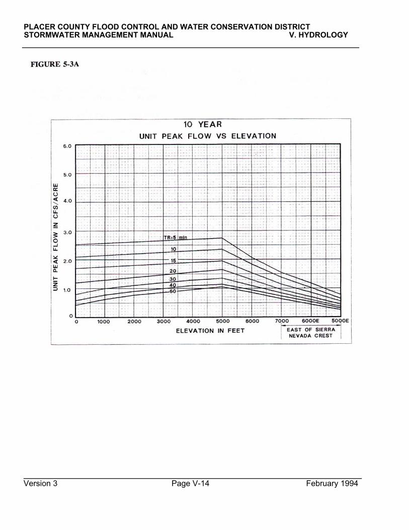
PLACER COUNTY FLOOD CONTROL AND WATER CONSERVATION DISTRICT STORMWATER MANAGEMENT MANUAL V. HYDROLOGY
Version 3 Page V-14 February 1994

PLACER COUNTY FLOOD CONTROL AND WATER CONSERVATION DISTRICT STORiVIWATER MANAGEMENT MANUAL V. HYDROLOGY
FIGURE 5-3B
Version 3 Page V-15 February 1994

PLACER COUNTY FLOOD CONTROL AND WATER CONSERVATION DISTRICT STORMWATER MANAGEMENT MANUAL V. HYDROLOGY FIGURE 5-3C
Version 3 Page V-16 February 1994

PLACER COUNTY FLOOD CONTROL AND WATER CONSERVATION DISTRICTSTORMWATER MANAGEMENT MANUAL V. HYDROLOGY FIGURE 5-4
Version 3 February 1994Page V-17__________________________________________________________________________
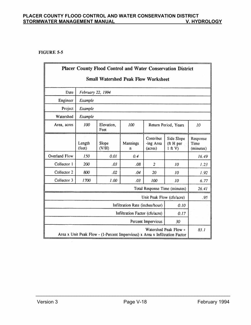
Version 3 Page V-18 February 1994
PLACER COUNTY FLOOD CONTROL AND WATER CONSERVATION DISTRICTSTORMWATER MANAGEMENT MANUAL V. HYDROLOGY
_______________________________________________________________________
PLACER COUNTY FLOOD CONTROL AND WATER CONSERVATION DISTRICTSTORMWATER MANAGEMENT MANUAL V. HYDROLOGY
response time of the total watershed. When the design of storage facilities is involved, the design storm shall be sufficiently long that runoff and storage volumes return to near their level at the beginning of the simulation. (3) Infiltration In general, an initial loss of zero and a constant infiltration rate shall be assumed. See the above section on infiltration for appropriate values. (4) Imperviousness The amount of impervious area is expressed as a fraction of the total area in percent. (5) Base Flow A base flow of 1.0 cfs per sq. mile should be assumed for major streams.
(6) Runoff Response The kinematic wave method shall be the basic approach to runoff response for developing watersheds. For convenience, a Clark or Snyder unit hydro-graph may be used if the parameters can be shown to give a response consistent with a kinematic wave analysis. Since the kinematic wave method responds dynamically to levels of precipitation intensity, this means that the unit graph parameters should also reasonably reflect the intensities expected in
3. HEC-1
a. Application HEC-1 shall be used for all basin master planning models and for the analysis of all major detention basins. HEC-1 is a generalized computer program developed and extensively used by the Corps of Engineers and others. HEC-1 provides flexibility by allowing many combinations of basic hydrologic processes to simulate the response of a watershed. HEC-1 is supported by the Corps of Engineers, but technical assistance and microcomputer versions of the program outside of the Corps are provided by several sources in the private sector. Copies of the micro-computer version and limited technical support are also available from the Placer County Flood Control District. b. Criteria The following criteria and guidelines apply to the use of HEC-1 for Placer County hydrology: (1) Simulation Time Step The simulation time step specified in HEC-1 will be 5 minutes for all watersheds with a response time greater than 10 minutes, and 1 minute for all watersheds with a response time of less than 10 minutes.
(2) Design Storms The precipitation which defines the design storm is specified period by period as input to HEC-1. Design storm criteria are specified under Precipitation above. The following additional criteria apply as well:
(a) Kinematic Wave
i) Simplification The representation of a watershed with the kinematic wave model requires great simplification and reduction. Inferences about the complex behavior of watershed are made from the behavior of an idealized representation composed of a few overland flow and channel elements.
Parameters chosen for elements are typical of the watershed and do not necessarily represent specific, physical elements. (b) Duration The duration of the design
storm should at least exceed four times the
Version 3 Page V-19 February 1994

PLACER COUNTY FLOOD CONTROL AND WATER CONSERVATION DISTRICT STORMWATER MANAGEMENT MANUAL V. HYDROLOGY
ii) Separately Connected Overland Flow Arms, Separately connected overland flow areas with significantly different characteristics, as often occurs in developed areas, should be represented by two overland flow elements. The surfaces involved with a typical 1/4 acre single family residence, for example, include roof, lawn, driveway, and street surfaces. It is appropriate to represent these surfaces with two overland elements: a smooth one for roofs, driveways and streets, and a rough one for the landscaped and lawn areas. Each element is connected, separately and independently, with a common collector. iii) Channel Representation The kinematic wave procedure is appropriate for represen-tation of channel routing where channel storage does not attenuate peak flows, such as engineered channels. Other procedures, such as the Muskingum-Cunge procedure, are appropriate for channels where attenuation would occur, such as in natural channels. These procedures are discussed below under "Channel Routing" . iv) Maximum Watershed Size The largest watershed described by one set of kinematic wave parameters should not exceed one (1) square mile in area. (b) Clark Instantaneous Unit Hydrograph The Clark parameters are tc and R. tc relates mainly to the response time and R to overland storage distributed throughout the watershed. Note the Clark tc is defined differently from and does not have the same values as the tc computed in the simplified graphical method above. More information on the Clark method may be found in the HEC-1 Users Manual.
(c) Snyder Unit Hydrograph The Snyder unit hydrograph parameters are basin lag and a peaking coefficient. More information on the
Snyder method may be found in the HEC-1 Users Manual.
(7) Channel Routing Channel routing reflects the time delay and attenuation due to channel and overbank storage of a flood wave as it moves downstream. Constrictions such as road culverts may further significantly attenuate peak runoff. Significant constrictions should be separately represented as a level pond in a Modified-Puls routing if they are not otherwise reflected in a routing scheme for the stream channel.(a) Muskingum-Cunge Method The Muskingum-Cunge method is appropriate for most channel routing. This method requires specification of a representative, uniform channel cross-section, slope, and Manning's n values. The uniform channel cross-section may be represented as a trapezoid, square or rounded bottom, or an eight-point section. The eight point section should be used for natural streams where the channel and flood-plain are clearly differentiated. The method should not be used where a backwater exists from a downstream obstruction. This is most likely to occur over long reaches where slopes are nearly flat. (b) Modified Puls Method The modified Puls method is appropriate when detailed cross section data are available, such as those used in a backwater analysis by FEMA. The modified Puls method is based on a storage-discharge relationship for a reach. (This relationship may be generated from cross section data with HEC-2). Subreaches are appropriate for modified Puls so that the travel time (based on celerity) through a subreach is approximately equal to the simulation time interval.
Version 3 Page V-20 February 1994

PLACER COUNTY FLOOD CONTROL AND WATER CONSERVATION DISTRICTSTORMWATER MANAGEMENT MANUAL V. HYDROLOGY
Data used for frequency curves will be adjusted, if necessary, to reflect changes in basin conditions, primarily but not limited to development and drainage and flood control improvements. The log-Pearson Type III method as outlined in Bulletin 17B shall be used for the statistical analysis of runoff records.
(c) Muskingum Method The Muskingum routing method is a simple method appropriate when detailed cross-section data is not available. It is based on a linear relationship between storage and discharge. The Muskingum parameters for a single reach: K the total travel time in hours for the reach. K is based on the celerity, the rate at which the flood wave propagates downstream. X, a coefficient which reflects the average
channel shape as follows:
(no attenuation)
Placer streamssome overbank (typical of South
Swamps, ponds (max. attenuation) 0
N, the number of subreaches to use. K/N should be approximately equal to the simulation time interval, and must be chosen within the following constraints:
2 (1-X)N N∆t 2X
4. Statistical Analyses Since streamflow records virtually do not exist for Placer County streams, statistical analysis of recorded streamflows can only be used at best to supplement the synthesis of relationships between flow and frequency. As streamflow data becomes available over time, however, it will be increasingly useful to the evaluation of hydrology in the region.
Version 3 Page V-21 February 1994
Trapezoidal, no overbank
Well-defined channel with
1 <
K <
1

PLACER COUNTY FLOOD CONTROL AND WATER CONSERVATION DISTRICT STORMWATER MANAGEMENT MANUAL V. HYDROLOGY REFERENCES 1. California Department of Water
Resources, Rainfall Depth-Duration-Frequency for California, Bulletin 190, Microfiche update.
2. Corps of Engineers, Hydrologic
Engineering Center, HEC-1, Flood HydrogWh Package. Users Manual, September 1990.
3. Humphrey, John H. El Dorado County
Hydrology Manual, Unpublished Draft, August 1991.
4. Humphrey, John H. and Wesley H. Blood,
Design Storm Methodology for Placer oun , 1989.
5. Linsley, Ray K., Max A. Kohler, and
Joseph L.H. Paulhus, Hydrology for Engineers, McGraw-Hill, 1958.
6. Miller, J.F., R.H. Frederick, and R.J.
Tracey, Precipitation-Frequency atlas of the Western United States. Vol, XI: California. NOAA Atlas 2, National Weather Service, 1973.
7. Overton, Donald E. and Michael E.
Meadows, Stormwater Modeling, Academic Press, 1976.
8. Soil Conservation Service, Technical
Release 55. Urban Hydrology for Small Watersheds, 1986.
Version 3 Page V-22 February 1994

PLACER COUNTY FLOOD CONTROL AND WATER CONSERVATION DISTRICT STORMWATER MANAGEMENT MANUAL V. HYDROLOGY
APPENDIX V-A
PRECIPITATION DATA
Version 3 February 1994
Page V-A-1

PLACER COUNTY FLOOD CONTROL AND WATER CONSERVATION DISTRICT STORMWATER MANAGEMENT MANUAL V. HYDROLOGY
Table 5-A-1 Depth-Duration-Frequency Coefficients
150 - 3000 feet elevation
West of Sierra Nevada Crest
Depths in inches at 150 feet Duration 2yr 5yr 10yr 25yr 50yr 100yr 200yr 500yr 5m 0.13 0.20 0.25 0.32 0.38 0.44 0.49 0.58 10m 0.19 0.29 0.36 0.46 0.54 0.62 0.70 0.82 15m 0.23 0.35 0.43 0.55 0.64 0.73 0.82 0.96 30m 0.32 0.47 0.57 0.72 0.83 0.94 1.04 1.22 1h 0.45 0.64 0.77 0.94 1.07 1.21 1.33 1.53 2h 0.64 0.88 1.04 1.26 1.42 1.59 1.76 2.00 3h 0.77 1.04 1.23 1.47 1.66 1.85 2.03 2.31 6h 1.06 1.40 1.65 1.95 2.22 2.23 2.75 3.10 12h 1.43 1.91 2.24 2.67 3.00 3.30 3.60 4.00 1d 1.90 2.50 2.98 3.46 3.85 4.25 4.60 5.20 2d 2.51 3.40 3.95 4.65 5.15 5.70 6.20 7.00 3d 3.00 4.07 4.65 5.50 6.20 6.80 7.50 8.40 5d 3.61 4.91 5.76 6.85 7.63 8.42 9.20 10.29 10d 4.73 6.44 7.54 8.96 9.97 11.01 11.95 13.45
Change in depth, inches per 1000 feet Duration 2yr 5yr 10yr 25yr 50yr 100yr 200yr 500yr 5m 0.007 0.000 -0.003 -0.007 -0.017 -0.023 -0.027 -0.037 10m 0.007 0.003 0.000 -0.010 -0.020 -0.027 -0.037 -0.050 15m 0.017 0.013 0.013 0.003 0.000 -0.007 -0.013 -0.027 30m 0.030 0.040 0.040 0.040 0.040 0.040 0.040 0.030 1h 0.063 0.087 0.100 0.120 0.133 0.137 0.157 0.173 2h 0.107 0.157 0.193 0.230 0.260 0.287 0.313 0.350 3h 0.143 0.220 0.263 0.327 0.373 0.413 0.457 0.513 6h 0.230 0.357 0.433 0.540 0.593 0.733 0.757 0.850 12h 0.453 0.663 0.820 0.977 1.127 1.250 1.400 1.600 1d 0.700 1.037 1.240 1.547 1.783 1.983 2.200 2.500 2d 1.163 1.667 2.017 2.483 2.850 3.167 3.533 4.000 3d 1.647 2.343 2.850 3.500 3.933 4.383 4.833 5.533 5d 2.287 3.230 3.913 4.717 5.390 5.960 6.600 7.570 10d 3.490 4.920 5.987 7.180 8.177 8.997 10.350 11.683
Version 3 February 1994
Page V-A-2

PLACER COUNTY FLOOD CONTROL AND WATER CONSERVATION DISTRICT STORMWATER MANAGEMENT MANUAL V. HYDROLOGY
Table 5-A-1 (continued) Depth-Duration-Frequency Coefficients
3000 - 5000 feet elevation
West of Sierra Nevada Crest
Depths in inches at 3000 feet Duration 2yr 5yr 10yr 25yr 50yr 100yr 200yr 500yr 5m 0.15 0.20 0.24 0.30 0.33 0.37 0.41 0.47 10m 0.21 0.30 0.36 0.43 0.48 0.54 0.59 0.67 15m 0.28 0.39 0.47 0.56 0.64 0.71 0.78 0.88 30m 0.41 0.58 0.70 0.85 0.95 1.07 1.18 1.33 1h 0.64 0.90 1.07 1.30 1.47 1.62 1.80 2.05 2h 0.96 1.35 1.62 1.95 2.20 2.45 2.70 3.05 3h 1.20 1.70 2.02 2.45 2.78 3.09 3.40 3.85 6h 1.75 2.47 2.95 3.57 4.00 4.50 4.95 5.65 12h 2.79 3.90 4.70 5.60 6.38 7.05 7.80 8.80 1d 4.00 5.61 6.70 8.10 9.20 10.20 11.20 12.70 2d 6.00 8.40 10.00 12.10 13.70 15.20 16.80 19.00 3d 7.94 11.10 13.20 16.00 18.00 19.95 22.00 25.00 5d 10.47 14.60 17.50 21.00 23.80 26.30 29.00 33.00 10d 15.20 21.20 25.50 30.50 34.50 38.00 43.00 48.50
Change in depth, inches per 1000 feet Duration 2yr 5yr 10yr 25yr 50yr 100yr 200yr 500yr 5m 0.000 0.000 0.000 0.010 0.010 0.010 0.010 0.010 10m 0.000 0.000 0.010 0.010 0.010 0.020 0.020 0.030 15m 0.000 0.000 0.010 0.010 0.020 0.020 0.030 0.040 30m 0.000 0.010 0.010 0.020 0.030 0.040 0.050 0.060 1h 0.000 0.010 0.020 0.040 0.050 0.070 0.090 0.100 2h 0.010 0.020 0.040 0.070 0.090 0.120 0.150 0.180 3h 0.010 0.030 0.060 0.100 0.130 0.170 0.200 0.250 6h 0.030 0.060 0.120 0.180 0.230 0.300 0.360 0.440 12h 0.060 0.120 0.210 0.340 0.430 0.510 0.620 0.760 1d 0.120 0.240 0.400 0.600 0.740 0.920 1.100 1.350 2d 0.240 0.460 0.730 1.080 1.310 1.600 1.900 2.320 3d 0.370 0.690 1.050 1.500 1.720 2.180 2.600 3.300 5d 0.640 1.150 1.650 2.350 2.750 3.350 3.950 4.750 10d 1.350 2.350 3.100 4.250 5.000 5.800 6.800 8.250
Version 3 February 1994
Page V-A-3

PLACER COUNTY FLOOD CONTROL AND WATER CONSERVATION DISTRICT STORMWATER MANAGEMENT MANUAL V. HYDROLOGY
Table 5-A-1 (continued) Depth-Duration-Frequency Coefficients
Above 5000 feet elevation
West of Sierra Nevada Crest
Depths in inches at 5000 ft Elevation Duration 2yr 5yr 10yr 25yr 50yr 100yr 200yr 500yr 5m 0.15 0.20 0.25 0.31 0.34 0.39 0.43 0.50 10m 0.21 0.30 0.37 0.45 0.50 0.57 0.63 0.72 15m 0.28 0.40 0.48 0.59 0.67 0.76 0.84 0.95 30m 0.41 0.59 0.73 0.89 1.01 1.15 1.28 1.45 1h 0.65 0.92 1.12 1.38 1.58 1.76 1.97 2.26 2h 0.98 1.39 1.71 2.10 2.39 2.69 3.00 3.42 3h 1.22 1.76 2.15 2.65 3.04 3.43 3.81 4.35 6h 1.80 2.59 3.18 3.93 4.47 5.10 5.67 6.53 12h 2.90 4.14 5.13 6.27 7.24 8.07 9.04 10.32 1d 4.23 6.09 7.50 9.30 10.68 12.04 13.40 15.40 2d 6.48 9.32 11.46 14.26 16.32 18.40 20.60 23.64 3d 8.68 12.48 15.30 19.00 21.44 24.31 27.20 31.60 5d 11.75 16.90 20.80 25.70 29.30 33.00 36.90 42.50 10d 17.90 25.90 31.70 39.00 44.50 49.60 56.60 65.00
Change in depth, inches per 1000 feet Duration 2yr 5yr 10yr 25yr 50yr 100yr 200yr 500yr 5m -0.030 -0.040 -0.050 -0.060 -0.070 -0.080 -0.090 -0.100 10m -0.040 -0.060 -0.070 -0.090 -0.100 -0.110 -0.130 -0.150 15m -0.050 -0.070 -0.090 -0.110 -0.130 -0.140 -0.160 -0.190 30m -0.070 -0.100 -0.130 -0.160 -0.190 -0.230 -0.240 -0.280 1h -0.100 -0.140 -0.190 -0.240 -0.280 -0.330 -0.370 -0.430 2h -0.150 -0.210 -0.280 -0.360 -0.410 -0.490 -0.560 -0.650 3h -0.190 -0.260 -0.340 -0.450 -0.520 -0.600 -0.700 -0.810 6h -0.280 -0.380 -0.510 -0.670 -0.780 -0.920 -1.060 -1.250 12h -0.410 -0.550 -0.750 -0.990 -1.160 -1.370 -1.600 -1.850 1d -0.600 -0.810 -1.100 -1.480 -1.750 -2.200 -2.450 -2.850 2d -0.860 -1.170 -1.600 -2.200 -2.600 -3.100 -3.700 -4.300 3d -1.050 -1.450 -1.950 -2.700 -3.200 -3.800 -4.600 -5.300 5d -1.400 -1.900 -2.600 -3.650 -4.300 -5.200 -6.300 -7.300 10d -2.050 -2.800 -3.850 -5.400 -6.500 -7.900 -9.600 -11.000
Version 3 February 1994
Page V-A-4

PLACER COUNTY FLOOD CONTROL AND WATER CONSERVATION DISTRICT STORMWATER MANAGEMENT MANUAL V. HYDROLOGY
Table 5-A-1 (continued) Depth-Duration-Frequency Coefficients
Above 5000 feet elevation
East of Sierra Nevada Crest
Depths in inches at 5000 ft Elevation Duration 2yr 5yr 10yr 25yr 50yr 100yr 200yr 500yr 5m 0.05 0.07 0.08 0.09 0.10 0.11 0.12 0.13 10m 0.08 0.10 0.12 0.14 0.15 0.17 0.18 0.20 15m 0.11 0.15 0.17 0.20 0.22 0.24 0.25 0.28 30m 0.16 0.21 0.24 0.27 0.30 0.33 0.36 0.39 1h 0.25 0.32 0.37 0.43 0.47 0.52 0.56 0.62 2h 0.36 0.47 0.54 0.62 0.69 0.73 0.82 0.90 3h 0.47 0.62 0.71 0.82 0.90 0.98 1.06 1.17 6h 0.76 0.99 1.15 1.32 1.45 1.59 1.71 1.90 12h 1.15 1.49 1.71 1.99 2.20 2.38 2.59 2.83 1d 1.74 2.38 2.60 3.03 3.34 3.70 3.95 4.35 2d 2.57 3.40 3.98 4.55 5.00 5.50 5.95 6.60 3d 3.31 4.30 5.01 5.75 6.15 6.90 7.43 8.20 5d 4.50 5.90 6.70 7.90 8.63 9.55 10.30 11.30 10d 7.00 9.20 10.50 12.20 13.50 14.80 15.90 17.30
Change in depth, inches per 1000 feet Duration 2yr 5yr 10yr 25yr 50yr 100yr 200yr 500yr 5m 0.010 0.025 0.035 0.045 0.050 0.055 0.060 0.070 10m 0.025 0.040 0.050 0.065 0.075 0.080 0.095 0.110 15m 0.040 0.055 0.070 0.085 0.100 0.115 0.130 0.150 30m 0.055 0.080 0.100 0.135 0.150 0.170 0.190 0.215 1h 0.100 0.155 0.185 0.235 0.275 0.300 0.340 0.390 2h 0.140 0.210 0.255 0.325 0.365 0.435 0.465 0.535 3h 0.185 0.270 0.335 0.415 0.480 0.560 0.620 0.690 6h 0.280 0.415 0.495 0.640 0.745 0.855 0.945 1.075 12h 0.495 0.755 0.920 1.155 1.300 1.485 1.605 1.885 1d 0.830 1.190 1.550 1.885 2.140 2.400 2.725 3.075 2d 1.175 1.710 2.110 2.650 2.900 3.300 3.625 4.200 3d 1.395 2.100 2.595 3.125 3.675 4.050 4.535 5.150 5d 1.700 2.550 3.250 3.950 4.535 5.225 5.700 6.500 10d 2.400 3.500 4.500 5.400 6.250 7.100 8.050 9.350
Version 3 February 1994
Page V-A-5

PLACER COUNTY FLOOD CONTROL AND WATER CONSERVATION DISTRICT STORMWATER MANAGEMENT MANUAL V. HYDROLOGY
Table 5-A-2 Depths for Selected Elevations
2-yr Event
Duration
Elev Dir 5m 10m 15m 30m 1h 2h 3h 6h 12h 1d 5d 10d 100 W 0.13 0.19 0.23 0.32 0.45 0.64 0.77 1.06 1.43 1.90 3.61 4.73 200 W 0.13 0.19 0.23 0.32 0.46 0.65 0.78 1.08 1.48 1.97 3.84 5.08 300 W 0.13 0.19 0.23 0.33 0.46 0.66 0.80 1.11 1.52 2.04 4.07 5.43 400 W 0.13 0.19 0.24 0.33 0.47 0.67 0.81 1.13 1.57 2.11 4.30 5.78 500 W 0.13 0.19 0.24 0.33 0.48 0.68 0.83 1.15 1.61 2.18 4.52 6.13 1000 W 0.14 0.20 0.25 0.35 0.51 0.74 0.90 1.27 1.84 2.53 5.67 7.87 1200 W 0.14 0.20 0.25 0.35 0.52 0.76 0.93 1.31 1.93 2.67 6.13 8.57 2000 W 0.14 0.20 0.26 0.38 0.57 0.84 1.04 1.50 2.29 3.23 7.96 11.36 3000 W 0.15 0.21 0.28 0.41 0.63 0.95 1.18 1.73 2.74 3.93 10.24 14.85 4000 W 0.15 0.21 0.28 0.41 0.64 0.97 1.21 1.78 2.85 4.12 11.11 16.55 5000 W 0.15 0.21 0.28 0.41 0.64 0.98 1.22 1.81 2.91 4.24 11.75 17.90 6000 W 0.12 0.17 0.23 0.34 0.55 0.83 1.03 1.52 2.49 3.63 10.35 15.85 7000 W 0.09 0.13 0.18 0.27 0.45 0.68 0.84 1.24 2.08 3.03 8.95 13.80 6000 E 0.06 0.10 0.15 0.22 0.35 0.50 0.65 1.04 1.64 2.57 6.20 9.40 5000 E 0.05 0.08 0.11 0.16 0.25 0.36 0.47 0.76 1.15 1.74 4.50 7.00
5-yr Event
Duration Elev Dir 5m 10m 15m 30m 1h 2h 3h 6h 12h 1d 5d 10d 100 W 0.20 0.29 0.35 0.47 0.64 0.88 1.04 1.40 1.91 2.50 4.91 6.44 200 W 0.20 0.29 0.35 0.47 0.65 0.90 1.06 1.44 1.98 2.60 5.23 6.93 300 W 0.20 0.29 0.35 0.48 0.66 0.91 1.08 1.47 2.04 2.71 5.56 7.42 400 W 0.20 0.29 0.35 0.48 0.67 0.93 1.11 1.51 2.11 2.81 5.88 7.92 500 W 0.20 0.29 0.36 0.49 0.67 0.94 1.13 1.54 2.18 2.91 6.20 8.41 1000 W 0.20 0.29 0.36 0.51 0.72 1.02 1.24 1.72 2.51 3.43 7.82 10.87 1200 W 0.20 0.29 0.36 0.51 0.74 1.05 1.28 1.79 2.64 3.64 8.46 11.85 2000 W 0.20 0.30 0.37 0.55 0.81 1.18 1.46 2.08 3.17 4.47 11.05 15.79 3000 W 0.20 0.30 0.39 0.59 0.89 1.34 1.68 2.44 3.83 5.51 14.28 20.71 4000 W 0.20 0.30 0.39 0.59 0.91 1.37 1.73 2.53 4.02 5.85 15.75 23.55 5000 W 0.20 0.30 0.39 0.60 0.92 1.39 1.76 2.59 4.14 6.09 16.90 25.90 6000 W 0.16 0.24 0.33 0.49 0.78 1.18 1.50 2.21 3.59 5.28 15.00 23.10 7000 W 0.12 0.18 0.26 0.39 0.64 0.97 1.24 1.83 3.04 4.47 13.10 20.30 6000 E 0.09 0.14 0.21 0.29 0.47 0.68 0.89 1.40 2.24 3.57 8.45 12.70 5000 E 0.07 0.10 0.15 0.21 0.32 0.47 0.62 0.99 1.49 2.38 5.90 9.20
Version 3 February 1994
Page V-A-6

PLACER COUNTY FLOOD CONTROL AND WATER CONSERVATION DISTRICT STORMWATER MANAGEMENT MANUAL V. HYDROLOGY
Table 5-A-2 (cont'd) Depths for Selected Elevations
10-yr Event
Duration
Elev Dir 5m 10m 15m 30m 1h 2h 3h 6h 12h 1d 5d 10d 100 W 0.25 0.36 0.43 0.57 0.77 1.04 1.23 1.65 2.24 2.98 5.76 7.54 200 W 0.25 0.36 0.43 0.57 0.78 1.06 1.26 1.69 2.32 3.10 6.15 8.14 300 W 0.25 0.36 0.43 0.58 0.79 1.08 1.28 1.74 2.40 3.23 6.54 8.74 400 W 0.25 0.36 0.43 0.58 0.80 1.10 1.31 1.78 2.49 3.35 6.93 9.34 500 W 0.25 0.36 0.44 0.59 0.81 1.12 1.34 1.82 2.57 3.48 7.33 9.93 1000 W 0.25 0.36 0.44 0.61 0.86 1.21 1.47 2.04 2.98 4.10 9.28 12.93 1200 W 0.25 0.36 0.44 0.61 0.88 1.25 1.52 2.13 3.14 4.34 10.06 14.13 2000 W 0.24 0.36 0.45 0.65 0.96 1.41 1.73 2.47 3.80 5.34 13.19 18.92 3000 W 0.24 0.36 0.47 0.69 1.06 1.60 1.99 2.91 4.62 6.58 17.11 24.90 4000 W 0.24 0.37 0.48 0.71 1.09 1.66 2.08 3.07 4.91 7.10 19.15 28.60 5000 W 0.24 0.38 0.49 0.72 1.11 1.70 2.14 3.19 5.12 7.50 20.80 31.70 6000 W 0.20 0.30 0.39 0.60 0.93 1.43 1.81 2.67 4.38 6.40 18.20 27.85 7000 W 0.15 0.23 0.30 0.47 0.74 1.15 1.47 2.16 3.63 5.30 15.60 24.00 6000 E 0.12 0.17 0.24 0.34 0.56 0.80 1.04 1.64 2.63 4.15 9.95 15.00 5000 E 0.08 0.12 0.17 0.24 0.37 0.54 0.71 1.15 1.71 2.60 6.70 10.50
25-yr Event
Duration Elev Dir 5m 10m 15m 30m 1h 2h 3h 6h 12h 1d 5d 10d 100 W 0.32 0.46 0.55 0.72 0.94 1.26 1.47 1.95 2.67 3.46 6.85 8.96 200 W 0.32 0.46 0.55 0.72 0.95 1.28 1.50 2.00 2.77 3.61 7.32 9.68 300 W 0.32 0.46 0.55 0.73 0.96 1.31 1.54 2.06 2.87 3.77 7.79 10.40 400 W 0.32 0.46 0.55 0.73 0.98 1.33 1.57 2.11 2.96 3.92 8.27 11.11 500 W 0.32 0.46 0.55 0.74 0.99 1.35 1.60 2.17 3.06 4.08 8.74 11.83 1000 W 0.31 0.45 0.55 0.76 1.05 1.47 1.76 2.44 3.55 4.85 11.10 15.42 1200 W 0.31 0.45 0.55 0.76 1.07 1.51 1.83 2.54 3.74 5.16 12.04 16.86 2000 W 0.31 0.44 0.56 0.80 1.17 1.70 2.09 2.98 4.53 6.40 15.81 22.60 3000 W 0.30 0.43 0.56 0.84 1.29 1.93 2.42 3.52 5.50 7.95 20.53 29.78 4000 W 0.31 0.44 0.57 0.87 1.34 2.02 2.55 3.75 5.94 8.70 23.35 34.75 5000 W 0.32 0.45 0.58 0.89 1.38 2.09 2.65 3.93 6.28 9.30 25.70 39.00 6000 W 0.25 0.36 0.48 0.73 1.14 1.74 2.20 3.26 5.28 7.82 22.05 33.60 7000 W 0.19 0.27 0.37 0.57 0.90 1.38 1.75 2.59 4.29 6.34 18.40 28.20 6000 E 0.14 0.20 0.28 0.41 0.67 0.94 1.24 1.96 3.14 4.91 11.85 17.60 5000 E 0.09 0.14 0.20 0.27 0.43 0.62 0.82 1.32 1.99 3.03 7.90 12.20
Version 3 February 1994
Page V-A-7

PLACER COUNTY FLOOD CONTROL AND WATER CONSERVATION DISTRICT STORMWATER MANAGEMENT MANUAL V. HYDROLOGY
Table 5-A-2 (cont'd) Depths for Selected Elevations
50-yr Event
Duration
Elev Dir 5m 10m 15m 30m 1h 2h 3h 6h 12h 1d 5d 10d 100 W 0.38 0.54 0.64 0.83 1.07 1.42 1.66 2.22 3.00 3.85 7.63 9.97 200 W 0.38 0.54 0.64 0.83 1.08 1.45 1.70 2.28 3.11 4.03 8.17 10.79 300 W 0.38 0.54 0.64 0.84 1.10 1.47 1.73 2.34 3.23 4.21 8.71 11.61 400 W 0.37 0.53 0.64 0.84 1.11 1.50 1.77 2.40 3.34 4.38 9.25 12.42 500 W 0.37 0.53 0.64 0.85 1.12 1.52 1.81 2.46 3.45 4.56 9.79 13.24 1000 W 0.36 0.52 0.64 0.87 1.19 1.65 2.00 2.75 4.01 5.45 12.48 17.33 1200 W 0.36 0.52 0.64 0.87 1.22 1.71 2.07 2.87 4.24 5.81 13.56 18.96 2000 W 0.35 0.50 0.64 0.91 1.32 1.91 2.37 3.35 5.14 7.24 17.87 25.51 3000 W 0.33 0.48 0.64 0.95 1.46 2.17 2.74 3.94 6.27 9.02 23.26 33.68 4000 W 0.34 0.49 0.66 0.98 1.52 2.29 2.91 4.23 6.81 9.94 26.55 39.50 5000 W 0.35 0.50 0.68 1.01 1.57 2.38 3.04 4.46 7.24 10.68 29.30 44.50 6000 W 0.27 0.40 0.54 0.82 1.30 1.98 2.52 3.69 6.08 8.93 25.00 38.00 7000 W 0.20 0.30 0.41 0.63 1.02 1.57 2.00 2.91 4.92 7.18 20.70 31.50 6000 E 0.15 0.23 0.32 0.45 0.75 1.06 1.38 2.20 3.50 5.48 13.16 19.75 5000 E 0.10 0.15 0.22 0.30 0.47 0.69 0.90 1.45 2.20 3.34 8.63 13.50
100-yr Event
Duration Elev Dir 5m 10m 15m 30m 1h 2h 3h 6h 12h 1d 5d 10d 100 W 0.44 0.62 0.73 0.94 1.21 1.59 1.85 2.23 3.30 4.25 8.42 11.01 200 W 0.44 0.62 0.73 0.94 1.22 1.62 1.89 2.30 3.42 4.45 9.02 11.91 300 W 0.44 0.61 0.73 0.95 1.24 1.65 1.93 2.38 3.55 4.65 9.61 12.81 400 W 0.43 0.61 0.73 0.95 1.25 1.68 1.97 2.45 3.67 4.84 10.21 13.71 500 W 0.43 0.61 0.73 0.96 1.26 1.70 2.02 2.52 3.80 5.04 10.80 14.61 1000 W 0.42 0.60 0.72 0.98 1.33 1.85 2.22 2.89 4.42 6.03 13.78 19.11 1200 W 0.41 0.59 0.72 0.98 1.36 1.91 2.30 3.04 4.67 6.43 14.98 20.91 2000 W 0.40 0.57 0.72 1.02 1.47 2.14 2.63 3.62 5.67 8.02 19.74 28.10 3000 W 0.37 0.54 0.71 1.06 1.61 2.42 3.05 4.36 6.92 10.00 25.70 37.10 4000 W 0.38 0.56 0.73 1.11 1.69 2.57 3.26 4.80 7.56 11.12 29.65 43.80 5000 W 0.39 0.58 0.75 1.15 1.76 2.69 3.43 5.10 8.07 12.04 33.00 49.60 6000 W 0.31 0.46 0.62 0.92 1.43 2.20 2.83 4.18 6.70 9.84 27.80 41.70 7000 W 0.23 0.35 0.48 0.69 1.10 1.71 2.23 3.26 5.33 7.64 22.60 33.80 6000 E 0.17 0.25 0.35 0.50 0.82 1.16 1.54 2.44 3.87 6.10 14.78 21.90 5000 E 0.11 0.17 0.24 0.33 0.52 0.73 0.98 1.59 2.38 3.70 9.55 14.80
Version 3 February 1994
Page V-A-8

PLACER COUNTY FLOOD CONTROL AND WATER CONSERVATION DISTRICT STORMWATER MANAGEMENT MANUAL V. HYDROLOGY
Table 5-A-2 (cont'd) Depths for Selected Elevations
200-yr Event
Duration Elev Dir 5m 10m 15m 30m 1h 2h 3h 6h 12h 1d 5d 10d 100 W 0.49 0.70 0.82 1.04 1.33 1.76 2.03 2.75 3.60 4.60 9.20 11.95 200 W 0.49 0.70 0.82 1.04 1.35 1.79 2.08 2.83 3.74 4.82 9.86 12.98 300 W 0.48 0.69 0.82 1.05 1.36 1.82 2.12 2.90 3.88 5.04 10.52 14.02 400 W 0.48 0.69 0.82 1.05 1.38 1.85 2.17 2.98 4.02 5.26 11.18 15.06 500 W 0.48 0.69 0.81 1.06 1.39 1.89 2.21 3.05 4.16 5.48 11.84 16.09 1000 W 0.47 0.67 0.81 1.08 1.47 2.04 2.44 3.43 4.86 6.58 15.14 21.26 1200 W 0.46 0.66 0.81 1.08 1.50 2.10 2.53 3.58 5.14 7.02 16.46 23.33 2000 W 0.44 0.63 0.80 1.12 1.63 2.35 2.90 4.19 6.26 8.78 21.74 31.61 3000 W 0.41 0.59 0.78 1.16 1.79 2.67 3.36 4.95 7.66 10.98 28.34 41.97 4000 W 0.42 0.61 0.81 1.23 1.89 2.85 3.60 5.31 8.42 12.30 32.95 49.80 5000 W 0.43 0.63 0.84 1.28 1.98 3.00 3.80 5.67 9.04 13.40 36.90 56.60 6000 W 0.34 0.50 0.68 1.04 1.60 2.44 3.11 4.61 7.44 10.95 30.60 47.00 7000 W 0.25 0.37 0.52 0.80 1.23 1.88 2.41 3.55 5.84 8.50 24.30 37.40 6000 E 0.18 0.28 0.38 0.55 0.90 1.28 1.68 2.65 4.19 6.67 16.00 23.95 5000 E 0.12 0.18 0.25 0.36 0.56 0.82 1.06 1.71 2.59 3.95 10.30 15.90
500-yr Event
Duration
Elev Dir 5m 10m 15m 30m 1h 2h 3h 6h 12h 1d 5d 10d 100 W 0.58 0.82 0.96 1.22 1.53 2.00 2.31 3.10 4.00 5.20 10.29 13.45 200 W 0.58 0.81 0.96 1.22 1.55 2.04 2.36 3.18 4.16 5.45 11.05 14.62 300 W 0.57 0.81 0.95 1.23 1.56 2.07 2.41 3.27 4.32 5.70 11.80 15.79 400 W 0.57 0.81 0.95 1.23 1.58 2.11 2.46 3.36 4.48 5.95 12.56 16.95 500 W 0.57 0.80 0.95 1.23 1.60 2.14 2.52 3.44 4.64 6.20 13.32 18.12 1000 W 0.55 0.77 0.94 1.25 1.69 2.32 2.77 3.87 5.44 7.45 17.10 23.96 1200 W 0.54 0.76 0.93 1.25 1.72 2.38 2.87 4.03 5.76 7.95 18.62 26.30 2000 W 0.51 0.72 0.91 1.28 1.86 2.66 3.28 4.72 7.04 9.95 24.67 35.65 3000 W 0.47 0.68 0.88 1.31 2.03 3.01 3.80 5.57 8.64 12.45 32.24 47.33 4000 W 0.48 0.70 0.92 1.39 2.15 3.23 4.10 6.09 9.56 14.05 37.75 56.75 5000 W 0.49 0.73 0.96 1.45 2.25 3.41 4.35 6.53 10.32 15.40 42.50 65.00 6000 W 0.40 0.57 0.76 1.17 1.83 2.77 3.54 5.28 8.47 12.55 35.20 54.00 7000 W 0.30 0.42 0.57 0.89 1.40 2.12 2.73 4.03 6.62 9.70 27.90 43.00 6000 E 0.20 0.31 0.43 0.61 1.01 1.43 1.86 2.97 4.72 7.43 17.80 26.65 5000 E 0.13 0.20 0.28 0.39 0.62 0.90 1.17 1.90 2.83 4.35 11.30 17.30
Version 3 February 1994
Page V-A-9

PLACER COUNTY FLOOD CONTROL AND WATER CONSERVATION DISTRICT STORMWATER MANAGEMENT MANUAL V. HYDROLOGY
Table 5-A-3 Intensities for Selected Elevations
2-yr Event
Duration
Elev Dir 5m 10m 15m 30m 1h 2h 3h 6h 12h 1d 100 W 1.56 1.14 0.92 0.64 0.45 0.32 0.26 0.18 0.12 0.08 200 W 1.57 1.14 0.93 0.65 0.46 0.33 0.26 0.18 0.12 0.08 300 W 1.58 1.15 0.93 0.65 0.46 0.33 0.27 0.18 0.13 0.09 400 W 1.59 1.15 0.94 0.66 0.47 0.34 0.27 0.19 0.13 0.09 500 W 1.59 1.16 0.95 0.66 0.48 0.34 0.28 0.19 0.13 0.09 1000 W 1.64 1.18 0.98 0.69 0.51 0.37 0.30 0.21 0.15 0.11 1200 W 1.65 1.19 0.99 0.71 0.52 0.38 0.31 0.22 0.16 0.11 2000 W 1.72 1.22 1.05 0.75 0.57 0.42 0.35 0.25 0.19 0.13 3000 W 1.80 1.26 1.12 0.81 0.63 0.48 0.39 0.29 0.23 0.16 4000 W 1.80 1.26 1.12 0.82 0.64 0.48 0.40 0.30 0.24 0.17 5000 W 1.80 1.26 1.12 0.82 0.64 0.49 0.41 0.30 0.24 0.18 6000 W 1.44 1.02 0.92 0.68 0.55 0.41 0.34 0.25 0.21 0.15 7000 W 1.08 0.78 0.72 0.54 0.45 0.34 0.28 0.21 0.17 0.13 6000 E 0.72 0.63 0.60 0.43 0.35 0.25 0.22 0.17 0.14 0.11 5000 E 0.60 0.48 0.44 0.32 0.25 0.18 0.16 0.13 0.10 0.07
5-yr Event
Duration Elev Dir 5m 10m 15m 30m 1h 2h 3h 6h 12h 1d 100 W 2.40 1.74 1.40 0.94 0.64 0.44 0.35 0.23 0.16 0.10 200 W 2.40 1.74 1.41 0.95 0.65 0.45 0.35 0.24 0.16 0.11 300 W 2.40 1.74 1.41 0.96 0.66 0.46 0.36 0.25 0.17 0.11 400 W 2.40 1.75 1.42 0.96 0.67 0.46 0.37 0.25 0.18 0.12 500 W 2.40 1.75 1.42 0.97 0.67 0.47 0.38 0.26 0.18 0.12 1000 W 2.40 1.76 1.45 1.01 0.72 0.51 0.41 0.29 0.21 0.14 1200 W 2.40 1.76 1.46 1.03 0.74 0.53 0.43 0.30 0.22 0.15 2000 W 2.40 1.77 1.50 1.09 0.81 0.59 0.49 0.35 0.26 0.19 3000 W 2.40 1.79 1.55 1.17 0.89 0.67 0.56 0.41 0.32 0.23 4000 W 2.40 1.80 1.56 1.18 0.91 0.69 0.58 0.42 0.34 0.24 5000 W 2.40 1.80 1.56 1.20 0.92 0.69 0.59 0.43 0.34 0.25 6000 W 1.92 1.44 1.32 0.98 0.78 0.59 0.50 0.37 0.30 0.22 7000 W 1.44 1.08 1.04 0.78 0.64 0.48 0.41 0.30 0.25 0.19 6000 E 1.14 0.84 0.82 0.58 0.47 0.34 0.30 0.23 0.19 0.15 5000 E 0.84 0.60 0.60 0.42 0.32 0.23 0.21 0.17 0.12 0.10
Version 3 February 1994
Page V-A-10

PLACER COUNTY FLOOD CONTROL AND WATER CONSERVATION DISTRICT STORMWATER MANAGEMENT MANUAL V. HYDROLOGY
Table 5-A-3 (cont'd) Intensities for Selected Elevations
10-yr Event
Duration
Elev Dir 5m 10m 15m 30m 1h 2h 3h 6h 12h 1d 100 W 3.00 2.16 1.72 1.14 0.77 0.52 0.41 0.28 0.19 0.12 200 W 3.00 2.16 1.73 1.15 0.78 0.53 0.42 0.28 0.19 0.13 300 W 2.99 2.16 1.73 1.16 0.79 0.54 0.43 0.29 0.20 0.13 400 W 2.99 2.16 1.74 1.16 0.80 0.55 0.44 0.30 0.21 0.14 500 W 2.99 2.16 1.74 1.17 0.81 0.56 0.45 0.30 0.21 0.14 1000 W 2.97 2.16 1.77 1.21 0.86 0.61 0.49 0.34 0.25 0.17 1200 W 2.96 2.16 1.78 1.23 0.88 0.63 0.51 0.35 0.26 0.18 2000 W 2.93 2.16 1.82 1.29 0.96 0.70 0.58 0.41 0.32 0.22 3000 W 2.90 2.16 1.87 1.37 1.06 0.80 0.66 0.48 0.38 0.27 4000 W 2.88 2.22 1.92 1.42 1.09 0.83 0.69 0.51 0.41 0.30 5000 W 2.88 2.28 1.96 1.44 1.11 0.85 0.71 0.53 0.43 0.31 6000 W 2.40 1.80 1.56 1.20 0.93 0.72 0.60 0.45 0.37 0.27 7000 W 1.80 1.38 1.20 0.94 0.74 0.57 0.49 0.36 0.30 0.22 6000 E 1.38 1.02 0.96 0.68 0.56 0.40 0.35 0.27 0.22 0.17 5000 E 0.96 0.72 0.68 0.48 0.37 0.27 0.24 0.19 0.14 0.11
25-yr Event
Duration Elev Dir 5m 10m 15m 30m 1h 2h 3h 6h 12h 1d 100 W 3.84 2.76 2.20 1.44 0.94 0.63 0.49 0.33 0.22 0.14 200 W 3.83 2.75 2.20 1.45 0.95 0.64 0.50 0.33 0.23 0.15 300 W 3.82 2.75 2.20 1.46 0.96 0.65 0.51 0.34 0.24 0.16 400 W 3.81 2.74 2.20 1.46 0.98 0.66 0.52 0.35 0.25 0.16 500 W 3.81 2.74 2.20 1.47 0.99 0.68 0.53 0.36 0.26 0.17 1000 W 3.76 2.71 2.21 1.51 1.05 0.73 0.59 0.41 0.30 0.20 1200 W 3.75 2.69 2.21 1.53 1.07 0.76 0.61 0.42 0.31 0.22 2000 W 3.68 2.65 2.22 1.59 1.17 0.85 0.70 0.50 0.38 0.27 3000 W 3.60 2.59 2.23 1.67 1.29 0.96 0.81 0.59 0.46 0.33 4000 W 3.72 2.64 2.28 1.74 1.34 1.01 0.85 0.63 0.50 0.36 5000 W 3.84 2.70 2.32 1.78 1.38 1.05 0.88 0.65 0.52 0.39 6000 W 3.00 2.16 1.92 1.46 1.14 0.87 0.73 0.54 0.44 0.33 7000 W 2.28 1.62 1.48 1.14 0.90 0.69 0.58 0.43 0.36 0.26 6000 E 1.62 1.23 1.14 0.81 0.67 0.47 0.41 0.33 0.26 0.20 5000 E 1.08 0.84 0.80 0.54 0.43 0.31 0.27 0.22 0.17 0.13
Version 3 February 1994
Page V-A-11

PLACER COUNTY FLOOD CONTROL AND WATER CONSERVATION DISTRICT STORMWATER MANAGEMENT MANUAL V. HYDROLOGY
Table 5-A-3 (cont'd) Intensities for Selected Elevations
50-yr Event
Duration
Elev Dir 5m 10m 15m 30m 1h 2h 3h 6h 12h 1d 100 W 4.56 3.24 2.56 1.66 1.07 0.71 0.55 0.37 0.25 0.16 200 W 4.54 3.23 2.56 1.67 1.08 0.72 0.57 0.38 0.26 0.17 300 W 4.52 3.22 2.56 1.68 1.10 0.74 0.58 0.39 0.27 0.18 400 W 4.50 3.20 2.56 1.68 1.11 0.75 0.59 0.40 0.28 0.18 500 W 4.48 3.19 2.56 1.69 1.12 0.76 0.60 0.41 0.29 0.19 1000 W 4.38 3.13 2.56 1.73 1.19 0.83 0.67 0.46 0.33 0.23 1200 W 4.34 3.11 2.56 1.75 1.22 0.85 0.69 0.48 0.35 0.24 2000 W 4.17 3.01 2.56 1.81 1.32 0.96 0.79 0.56 0.43 0.30 3000 W 3.97 2.89 2.56 1.89 1.46 1.09 0.91 0.66 0.52 0.38 4000 W 4.08 2.94 2.64 1.96 1.52 1.14 0.97 0.70 0.57 0.41 5000 W 4.20 3.00 2.72 2.02 1.57 1.19 1.01 0.74 0.60 0.44 6000 W 3.24 2.40 2.16 1.64 1.30 0.99 0.84 0.61 0.51 0.37 7000 W 2.40 1.80 1.64 1.26 1.02 0.79 0.67 0.48 0.41 0.30 6000 E 1.80 1.35 1.28 0.90 0.75 0.53 0.46 0.37 0.29 0.23 5000 E 1.20 0.90 0.88 0.60 0.47 0.34 0.30 0.24 0.18 0.14
100-yr Event
Duration Elev Dir 5m 10m 15m 30m 1h 2h 3h 6h 12h 1d 100 W 5.28 3.72 2.92 1.88 1.21 0.80 0.62 0.37 0.28 0.18 200 W 5.25 3.70 2.92 1.89 1.22 0.81 0.63 0.38 0.29 0.19 300 W 5.22 3.69 2.91 1.90 1.24 0.82 0.64 0.40 0.30 0.19 400 W 5.20 3.67 2.91 1.90 1.25 0.84 0.66 0.41 0.31 0.20 500 W 5.17 3.66 2.91 1.91 1.26 0.85 0.67 0.42 0.32 0.21 1000 W 5.03 3.57 2.89 1.95 1.33 0.92 0.74 0.48 0.37 0.25 1200 W 4.98 3.54 2.89 1.97 1.36 0.95 0.77 0.51 0.39 0.27 2000 W 4.76 3.41 2.87 2.03 1.47 1.07 0.88 0.60 0.47 0.33 3000 W 4.48 3.25 2.84 2.11 1.61 1.21 1.02 0.73 0.58 0.42 4000 W 4.56 3.36 2.92 2.22 1.69 1.28 1.09 0.80 0.63 0.46 5000 W 4.68 3.48 3.00 2.30 1.76 1.35 1.14 0.85 0.67 0.50 6000 W 3.72 2.76 2.48 1.84 1.43 1.10 0.94 0.70 0.56 0.41 7000 W 2.76 2.10 1.92 1.38 1.10 0.86 0.74 0.54 0.44 0.32 6000 E 1.98 1.50 1.42 1.00 0.82 0.58 0.51 0.41 0.32 0.25 5000 E 1.32 1.02 0.96 0.66 0.52 0.37 0.33 0.27 0.20 0.15
Version 3 February 1994
Page V-A-12

PLACER COUNTY FLOOD CONTROL AND WATER CONSERVATION DISTRICT STORMWATER MANAGEMENT MANUAL V. HYDROLOGY
Table 5-A-3 (cont'd) Intensities for Selected Elevations
200-yr Event
Duration
Elev Dir 5m 10m 15m 30m 1h 2h 3h 6h 12h 1d 100 W 5.88 4.20 3.28 2.08 1.33 0.88 0.68 0.46 0.30 0.19 200 W 5.85 4.18 3.27 2.09 1.35 0.90 0.69 0.47 0.31 0.20 300 W 5.82 4.16 3.27 2.10 1.36 0.91 0.71 0.48 0.32 0.21 400 W 5.78 4.13 3.26 2.10 1.38 0.93 0.72 0.50 0.34 0.22 500 W 5.75 4.11 3.26 2.11 1.39 0.94 0.74 0.51 0.35 0.23 1000 W 5.59 4.00 3.23 2.15 1.47 1.02 0.81 0.57 0.40 0.27 1200 W 5.52 3.96 3.22 2.17 1.50 1.05 0.84 0.60 0.43 0.29 2000 W 5.26 3.78 3.18 2.23 1.63 1.18 0.97 0.70 0.52 0.37 3000 W 4.94 3.56 3.13 2.31 1.79 1.33 1.12 0.82 0.64 0.46 4000 W 5.04 3.66 3.24 2.46 1.89 1.43 1.20 0.88 0.70 0.51 5000 W 5.16 3.78 3.36 2.56 1.98 1.50 1.27 0.94 0.75 0.56 6000 W 4.08 3.00 2.72 2.08 1.60 1.22 1.04 0.77 0.62 0.46 7000 W 3.00 2.22 2.08 1.60 1.23 0.94 0.80 0.59 0.49 0.35 6000 E 2.16 1.65 1.52 1.10 0.90 0.64 0.56 0.44 0.35 0.28 5000 E 1.44 1.08 1.00 0.72 0.56 0.41 0.35 0.28 0.22 0.16
500-yr Event
Duration Elev Dir 5m 10m 15m 30m 1h 2h 3h 6h 12h 1d 100 W 6.96 4.92 3.84 2.44 1.53 1.00 0.77 0.52 0.33 0.22 200 W 6.92 4.89 3.83 2.45 1.55 1.02 0.79 0.53 0.35 0.23 300 W 6.87 4.86 3.82 2.45 1.56 1.03 0.80 0.55 0.36 0.24 400 W 6.83 4.83 3.81 2.46 1.58 1.05 0.82 0.56 0.37 0.25 500 W 6.78 4.80 3.80 2.46 1.60 1.07 0.84 0.57 0.39 0.26 1000 W 6.56 4.65 3.74 2.49 1.69 1.16 0.92 0.64 0.45 0.31 1200 W 6.47 4.59 3.72 2.51 1.72 1.19 0.96 0.67 0.48 0.33 2000 W 6.12 4.35 3.63 2.55 1.86 1.33 1.09 0.79 0.59 0.41 3000 W 5.67 4.05 3.53 2.61 2.03 1.51 1.27 0.93 0.72 0.52 4000 W 5.76 4.20 3.68 2.78 2.15 1.62 1.37 1.01 0.80 0.59 5000 W 5.88 4.38 3.84 2.90 2.25 1.70 1.45 1.09 0.86 0.64 6000 W 4.80 3.42 3.04 2.34 1.83 1.38 1.18 0.88 0.71 0.52 7000 W 3.60 2.52 2.28 1.78 1.40 1.06 0.91 0.67 0.55 0.40 6000 E 2.40 1.86 1.72 1.21 1.01 0.72 0.62 0.50 0.39 0.31 5000 E 1.56 1.20 1.12 0.78 0.62 0.45 0.39 0.32 0.24 0.18
Version 3 February 1994
Page V-A-13

PLACER COUNTY FLOOD CONTROL AND WATER CONSERVATION DISTRICT STORMWATER MANAGEMENT MANUAL V. HYDROLOGY
Version 3 Page V-B-1 February 1994
APPENDIX V-B
DESIGN STORM PROCEDURES

PLACER COUNTY FLOOD CONTROL AND WATER CONSERVATION DISTRICT STORMWATER MANAGEMENT MANUAL V. HYDROLOGY
Version 3 Page V-B-2 February 1994
Introduction This appendix describes the procedures used to create a design storm as input to HEC-1 from the data presented in Chapter V and Appendix V-A. For convenience and reliability, these procedures have been incorporated in a computer program entitled "PDP". PDP runs on personal computers (under DOS) and is available from District staff. Time Distribution The design storm is derived from the depth vs duration data for the appropriate recurrence interval and elevation. The maximum depth (the depth for the same duration as the time interval, which is usually 5 minutes) is placed at the center of the distribution. Then, successively lesser incremental depths are computed as the differences in cumulative depths from the depth-duration data for succeedingly longer durations. These incremental depths are positioned alternately after and before the highest (center) intensity. Example 1-hour, 10 year design storm, 150 foot elevation, 5 minute time step: Step 1 Compute incremental period depths in order of rank. Cumulative depths are read or interpolated from the tables in Appendix V-A. Log-log interpolation is used when the depth for a given duration must be interpolated between tabulated depths (those marked below with * ). Cumulative Incremental Duration Depth Depth Rank minutes inches inches 1 5 0.250 0.250 2 10 0.360 0.110 3 15 0.430 0.070 4 20 0.483* 0.053 5 25 0.529* 0.046 6 30 0.570 0.041 7 35 0.609* 0.039 8 40 0.645* 0.036 9 45 0.679* 0.034 10 50 0.711* 0.032 11 55 0.741* 0.030 12 60 0.770 0.029 The equation for log-log interpolation between successive durations 1 and 2 is:

PLACER COUNTY FLOOD CONTROL AND WATER CONSERVATION DISTRICT STORMWATER MANAGEMENT MANUAL V. HYDROLOGY
Version 3 Page V-B-3 February 1994
d = d1(
t ) k
t1 where d = depth, inches t = duration, minutes and log (
d2 )
d1 k = log (t
2 ) t1
Step 2 Reorder the incremental depths with the maximum depth in the center, others alternating after and before the maximum. Time Depth Period minutes inches 1 5 0.030 2 10 0.034 3 15 0.039 4 20 0.046 5 25 0.070 6 30 0.250 7 35 0.110 8 40 0.053 9 45 0.041 10 50 0.036 11 55 0.032 12 60 0.029
PLACER COUNTY FLOOD CONTROL AND WATER CONSERVATION DISTRICT STORMWATER MANAGEMENT MANUAL V. HYDROLOGY
Version 3 Page V-B-4 February 1994
Spatial Distribution When to Use The spatial distribution of the design storm must be taken into account when the area of the overall watershed exceeds significantly the area in Table 5-1 for which the spatial distribution factor is 1.0. Table 5-1 provides factors to be used for modifying the depths for the most intense 1-hour period within the storm. The factors are constant at the boundary of the ellipse with the area shown in the first column of the table. The major axis of the ellipse is twice the minor axis, and the orientation of the ellipse is taken as the angle of the major axis relative to due north, with a positive angle measured clockwise. The length of the minor and major axes are shown in the last two columns of Table 5-1. Constant Value for One Watershed - No Subwatersheds In cases where the watershed is not divided into subwatersheds and the area of the watershed is not significantly greater than the area of the ellipse for which the factor is 1.0, the average precipitation for the watershed may be estimated as an area-weighted average considering the procedure described below for a more detailed watershed. A wide and pronounced variation in the spatial distribution of rainfall over the watershed may require subdivision into smaller watersheds to appropriately reflect the variation. Divided into Subwatersheds Precipitation for each subwatershed may be reasonably approximated as precipitation at a point near the centroid of the watershed. The procedure below is used. It is often necessary to repeat the procedure for various centerings and orientations of the ellipse. The elliptical distribution is properly centered and oriented when the maximum flow for the results for the storm recurrence interval. Usually, but not always, this is the centering which produces the highest, area-weighted average factor. Step 1 Determine the 1-hour factor for the point. The 1-hour factor may be found using a graphical procedure or an analytical one. Graphical A transparent map overlay is created at the scale of the map with concentric ellipses drawn for appropriate increments of the factors from Table 5-1. For example, ellipses may be drawn for 1.0, 0.9, 0.8, etc. The major and minor axis of the table areas are shown in the far right hand columns in Table 5-1. For other areas, the equations for the minor and major axis are:

PLACER COUNTY FLOOD CONTROL AND WATER CONSERVATION DISTRICT STORMWATER MANAGEMENT MANUAL V. HYDROLOGY
Version 3 Page V-B-5 February 1994
a = 2Aπ
b = 2 a where a = minor axis, miles b = major axis, miles A = area, square miles When the point falls between two of the ellipses on the overlay, the factor for the point is interpolated between the values for the bracketing pair of ellipses. Analytical The factor associated with the ellipse through the point is computed from position of the point relative to the ellipse, taking into account the angle of the major axis with due north. In the equations below, y is distance north, in miles, from an arbitrary origin, and x is the distance east in miles from the origin. The subscript p refers to the x-y coordinates of the point which is the centroid of the watershed, and the subscript c refers to the x-y coordinates of the center of the storm ellipse. α is the angle of the major axis with north in degrees clockwise.
′x = ( x - x ) - ( y - y )p c p ccos sinα α
′y = ( x - x ) +( y - y )p c p csin cosα α
a = 2 (x ) +(y )4
22
′′
b = 2a
A = ab4π

PLACER COUNTY FLOOD CONTROL AND WATER CONSERVATION DISTRICT STORMWATER MANAGEMENT MANUAL V. HYDROLOGY
Version 3 Page V-B-6 February 1994
Step 2 Modify the depth-duration relationships using the 1-hour factor. Look up the 1-hour factor in Table 5-1 corresponding to the ellipse area determined in step 1. The 1-hour depth is modified by simply multiplying it with the factor. Depths for durations of less than one hour are reduced so that the average intensity between any two durations is at least the average intensity between the next longer pair of durations, with the minimum intensity no less than that between the 1-hour and 2-hour durations, and so that the adjusted depths maintain a proportionality among themselves that is reasonably consistent with the proportionality among the unadjusted values. Example: 100-year event, 1200 feet elevation, 1-hour factor = 0.5 Unadjusted Adjusted Average Depth Depth Intensity Duration inches inches inches/hour 0 0 0 --- 5m .41 .104 1.25
10m .59 .174 .84 15m .72 .235 .73 30m .98 .395 .64
1h 1.36 .680 .57 2h 1.91 --- .55 Step 3) Compute the temporal distribution as described above using the adjusted depth-duration data for durations of one hour and less. Steps 1-3 are repeated for each subwatershed, then HEC-1 is ran to compute the runoff resulting from that particular centering and orientation of the ellipse. As noted above, it may be necessary to test several centerings to determine the centering which results in the maximum peak flow.

PLACER COUNTY FLOOD CONTROL AND WATER CONSERVATION DISTRICT STORMWATER MANAGEMENT MANUAL VI. DRAINAGE SYSTEMS
Version Page VI-1 July 1994
VI. DRAINAGE SYSTEMS A. Purpose This chapter specifies various design criteria, standards, guidelines for the design of systems which collect and convey runoff to an outlet. These systems are typically found in developed areas, and they include streets, conduits, and their appurtenances. Culverts for transverse crossings of open channels are also included. B. Principles and Policies 1. General The following general principles will be considered in the design of storm drainage facilities: a. Storm drainage planning, design, and construction will avoid increasing the storm drainage problems in any area, or transferring drainage problems from one location to another. Watershed boundaries shall not be altered, and flows shall not be diverted from one watershed to another without compelling reasons. b. Storm drains should use the natural drainage channel alignments whenever possible. c. Development plans shall provide a secondary surface flow escape path for flows in excess of the capacity of the primary piped or channelized drainage system without damage to structures. d. Storm drainage planning and design shall be consistent with the flood boundaries and floodways delineated and regulated by the National Flood Insurance Program or other studies, such as watershed master plans. e. Public storm drainage facilities shall normally be located within public road right-of-ways, unless specifically approved by the local jurisdiction, and shall be designed as permanent facilities with minimal maintenance costs. f. The points at which drainage enter and exit a project shall be at the same vertical and horizontal
location as exists before the project except by written and recorded agreement between adjacent landowners in the form of an easement. g. Fill or structures shall not be permitted to block drainage paths even if these paths function only in storms of rare occurrence. h. Storm drainage systems shall incorporate best management practices for the protection of water quality when required by the local jurisdiction. 2. Design storms All new development shall be planned and designed so that no damages occur to structures or improvements during the 100-year event and no inundation of private property occurs during the 10-year event. a. Local Drainage The 10-year event is the minimum design storm for new developments in all drainages and all dedicated drainage facilities will be sized for this event. The development plan will also identify the effects of the 100-year event and provisions will be made in the plan to prevent loss of life and damages to property during a 100-year event. b. Regional Drainage Regional drainage facilities are those identified as such in watershed plans, or have drainage areas greater than 200 acres. Regional drainage systems will be planned and designed for a 100-year event except where the cost of the system is clearly unjustifiable economically. Variances from the design frequency will be approved by the Flood Control District. Designs of major flood control facilities will consider the effects of events which are lesser in magnitude as well as greater than the design event. 3. Preliminary Drainage Plan Requirements A narrative drainage report and other pertinent information shall be submitted with any preliminary plan of development. Specific information is listed and described in a separate section at the end of this manual entitled Requirements for Submittals. Additional information may be required as
PLACER COUNTY FLOOD CONTROL AND WATER CONSERVATION DISTRICT STORMWATER MANAGEMENT MANUAL VI. DRAINAGE SYSTEMS
Version 5 Page VI-2 July 1994
appropriate. 4. Final Drainage Plan Requirements Construction plans shall be provided by the developer or his agent for review by the approving jurisdiction. Specific information is listed and described in a separate section at the end of this manual entitled Requirements for Submittals. Additional information may be required as appropriate. C. Streets and Gutters 1. Policy Streets may be used for the conveyance of storm drainage; however, the primary purpose and use of streets is for traffic. 10-year flows shall therefore be conveyed within the gutter, roadside ditches or swales, or underground within street areas. 2. Design Criteria a. Encroachments Limitations for pavement encroachment are presented in Table 6-1. When any of these encroachments are exceeded, a means of draining off the excess flow must be provided. b. Cross Street Flow Cross street flows shall not be allowed. Cross street flow may be runoff which has been flowing in a gutter and then flows across the street to the opposite gutter or to an inlet or may be flow from some external source, such as a drainage way, which will flow across the crown of a street when the conduit capacity beneath the street is exceeded. c. Walkover Curbs Walkover curbs shall be used at intersections in highly concentrated areas where large volumes of pedestrian traffic are likely. d. Alleys (1) Use Alleys shall not be used as storm runoff channels, except to convey internal block runoff to the streets. (2) Sections and Grade Alleys are typically designed with inverted crowns. The maximum and minimum grades and crown slopes shall be the
same as for streets. Where an alley intersects a street, the alley grade shall be raised above the street grade so flow within the street cannot move into the alley for the 10-year event. (3) Carrying Capacity The allowable carrying capacity of an alley shall be calculated as covered in the following sub-sections. If the quantity of flow exceeds that allowable, mid-block inlets or other methods must be utilized to remove portions of the flow from the alley surface. (4) Design Runoff All runoff from the 10-year event must be conveyed within the alley right of way.

PLACER COUNTY FLOOD CONTROL AND WATER CONSERVATION DISTRICT STORMWATER MANAGEMENT MANUAL VI. DRAINAGE SYSTEMS
Version Page VI-3 July 1994
TABLE 6-1 ALLOWABLE STREET ENCROACHMENTS
Type Profile 10-Year Storm 25-Year Storm 100-Year Storm
LOCAL Continuous Grade (uphill or downhill)
Travelled way is open to travel and does not carry stormwater flow.
Stormwater elevation does not exceed the top back of sidewalk. Maximum depth in travelled way - 6"
Maximum stormwater elevation is 4" above the top of curb and the storm- water flow cannot exceed 3 ft/sec.
Sag Points Stormwater elevation does not exceed the top back of sidewalk. Maximum depth in travelled way - 6". Centerline shall by dry.
Stormwater elevation does not exceed 4" above the top back of curb. Maximum depth in travelled way - 6".
Stormwater is a minimum of one foot below building pads. Ponding does not extend more than 120 feet from inlet (2 std. residential lot frontages) along any street segment.
COLLECTOR Continuous Grade (uphill or downhill)
Travelled way is open to travel and does not carry stormwater flow.
Stormwater elevation does not exceed the top back of sidewalk. Maximum depth in travelled way - 6".
Stormwater flow is contained within the right of way. The center 12 feet of roadway is clear of stormwater. The storm- water flow cannot exceed 3 ft/sec.
Sag Points Stormwater elevation does not exceed the top back of sidewalk. Maximum depth in travelled way - 6".
Stormwater elevation does not exceed 4" above the top back of curb. Maximum depth in travelled way - 6".
Stormwater flow is contained within the right of way. The center 12 feet of roadway is clear of stormwater. The storm- water flow cannot exceed 3 ft/sec. Maximum depth over sidewalks shall be 6".
ARTERIAL AND EXPRESSWAY
Continuous Grade (uphill or downhill)
All travel lanes are clear of stormwater flow. Bike lanes are allowed to be inundated. Stormwater flow contained within the right of way. Maximum depth over sidewalks shall be 6".
Sag Points All travel lanes are clear of stormwater flow. Bike lanes are allowed to be inundated. Stormwater flow contained within the right of way. Maximum depth over sidewalks shall be 6".
Note: Criteria reflect the possibility of a sidewalk separate from the curb and gutter.

PLACER COUNTY FLOOD CONTROL AND WATER CONSERVATION DISTRICT STORMWATER MANAGEMENT MANUAL VI. DRAINAGE SYSTEMS
Version 5 Page VI-4 July 1994
(a) Capacity The capacity shall be calculated using Mannings formula with a suitable "n" value. (b) Ponding See Table 6-1. (c) Limitations at Sidewalks See Table 6-1. i) Residential, Industrial, or Light Business Areas Where alleys are located in residential, industrial, or light commercial areas, flow from alleys may pass across the sidewalk for both the 10-year and 100-year events. ii) Concentrated Business Areas. When alleys are located in concentrated business areas of the types where walkover curbs might be installed, runoff from the 10-year event shall not be allowed to cross the sidewalks. Inlets shall be placed as necessary to intercept the flow before it reaches the sidewalk. For the 100-year event, runoff from the alley may flow across the sidewalk. e. Rural Streets In general, the majority of requirements for urban streets are applicable for rural streets. A major difference is that rural streets use roadside drainage ditches instead of curbs and gutters for drainage. Roadside ditches are planned and designed as open channels. D. Drainage Conduits This section is specific to the planning and design of underground drainage systems consisting of conduits -- round pipes or box culverts -- and various other related compon- ents such as inlets and manholes. 1. Policies a. Permanent Installations Underground drainage systems shall be designed as virtually permanent installations. b. Maintenance Ease Underground drainage systems shall be designed for ease of maintenance and repair.
2. Criteria a. General (1) Hydraulic Grade Line Closed conduit sections (pipes, boxes, etc.) shall be designed as flowing full, whenever possible. The hydraulic gradeline (HGL) shall at all points be at least six (6) inches below all manhole covers, gratings, and inlets when operating under a head at the 10-year design flow. (2) Minimum Velocity To prevent sedimentation, minimum velocity allowable in any closed conduit shall be two and one half (2 1/2) feet per second. Velocities shall be computed by using Manning's formula for pipes flowing full or half full, using "n" values as shown in Table 6-3. (3) Slopes Pipe slopes shall be less than 70 percent of critical slope or more than 130 percent of critical slope at design flow. The maximum design quantity of flow for any line steeper than critical slope shall be computed assuming that the flow is at critical slope and critical velocity. b. Drop Inlets (1) Spacing Max. spacing of drop inlets shall be 500 feet. (2) Design Cal Trans Type GO inlets with a bicycle-proof grate shall be used for all streets with gutters. (3) Capacity Inlet capacity shall allow for 50% blockage. (4) Hydraulic Grade Line The design HGL should be at least 6 inches below the gutter grade at the inlet to allow the inlet to function properly. The inlet should not be counted as accepting flow if there is a possibility the hydraulic grade will be above this level. c. Manholes (1) Pipe Location The location of pipes within a manhole should be designed to insure maximum

PLACER COUNTY FLOOD CONTROL AND WATER CONSERVATION DISTRICT STORMWATER MANAGEMENT MANUAL VI. DRAINAGE SYSTEMS
Version 5 Page VI-5 July 1994
efficiency. (2) Spacing Spacing of manholes shall generally be as shown in Table 6-2.
A manhole shall always be located at the end of short radius bends and at angle points of 10 degrees or more. Any local pipes that enter the storm drainage system shall enter the system at a manhole. (3) Direction Changes Short radius bends may be used on 24 inch and larger pipes when flow must undergo a direction change at a junction or bend. Reductions in headloss at manholes may be realized in this way. d. Computation Procedures The wetted perimeter of a pipe increases more rapidly than the area as the pipe approaches full capacity. Therefore, the capacity of a circular conduit at a given grade is the same at 91% and 100% ratios of d/D. Because it is impractical to design for the theoretical range where capacity exceeds that for the full conduit, open channel flow should only be assumed for d/D ratios of less than 0.90. (1) Basic The basic computations of the hydraulic grade line and conduit capacities shall be based on the Manning equation: V = 1.489R2/3S1/2 [6-1] n where V = velocity, feet per second R = hydraulic radius, feet: the cross sectional area divided by the wetted perimeter. S = slope of energy grade line, feet vertical per foot horizontal
n = roughness coefficient (see Table 6-3) (2) Roughness Values Values for n from Table 6-3 below will be used unless otherwise specified in this manual. (3) Hydraulic Grade Line The hydraulic grade line or HGL is computed from a known water surface elevation, usually the outlet condition, and the summation of head (energy) losses occurring in elements of the system due to friction and turbulence. These losses will be accounted for using the following criteria unless otherwise specified in this manual
TABLE 6-2 MANHOLE SPACING
Pipe Size
Maximum Spacing
24" or less 400 feet greater than 24" 600 feet

PLACER COUNTY FLOOD CONTROL AND WATER CONSERVATION DISTRICT STORMWATER MANAGEMENT MANUAL VI. DRAINAGE SYSTEMS
Ve
TABLE 6-3
MANNING N VALUES FOR DESIGN
C C C P S S C C N1)2)3)m4)in5)anth
rsion 5 Page VI-6 July 1994
OF DRAINAGE CONDUITS1
Type n2,3
orrugated Metal Pipe4
Annular 2-2/3" x 1/2" corrugation............................................................................................................... 0.025 3" x 1" " ....................................................................................................................... 0.028 5" x 1" " ....................................................................................................................... 0.026 6" x 1 " " ....................................................................................................................... 0.024 6" x 2" " ....................................................................................................................... 0.035 9" x 2" " ....................................................................................................................... 0.035 Helical5
2-2/3" x 1/2" corrugation, diameter <= 72 ………………………………………….….. 0.002 + 0.006 (diameter (inches) - 10) 0.3
diameter > 72" ............................................................................................................................ 0.024
oncrete Pipe Pre-cast ......................................................................................................................................... 0.012 Cast-in-place ................................................................................................................................. 0.013
oncrete Box .................................................................................................................................. 0.013
lastic Pipe Smooth Interior .............................................................................................................................. 0.012 Corrugated Interior ........................................................................................................................ 0.022
piral Rib Metal Pipe 3/4" W x 1" D @ 11-1/2" o/c........................................................................................................... 0.013 3/4" W x 3/4" D @ 7-1/2" o/c.......................................................................................................... 0.013
teel Pipe, Ungalvanized ................................................................................................................ 0.015
ast Iron Pipe ................................................................................................................................. 0.015
lay Sewer Pipe .............................................................................................................................. 0.013
otes: Source: CalTrans, Highway Design Manual Tabulated n values are for average field conditions. Tabulated n values apply to circular pipes flowing full. For noncircular or partially full conduits, thetabulated values ay be modified as shown in Appendix B of HDS No. 5, Hydraulic Design of Highway Culverts. For lined corrugated metal pipe, a composite roughness coefficient may be computed using the procedures outlined the HDS No. 5, Hydraulic Design of Highway Culverts. Alternative values adopted by FHWA used in place of CalTrans values. Thee values are for full flowing culverts d may not apply to culverts flowing partially full. These values may not be accepted by CalTrans or agencies using e CalTrans standards.

PLACER COUNTY FLOOD CONTROL AND WATER CONSERVATION DISTRICT STORMWATER MANAGEMENT MANUAL VI. DRAINAGE SYSTEMS
Version 5 Page VI-7 July 1994
(a) Friction Losses The Manning equation will be used to compute friction losses by solving for a value of Sf, the energy gradient, then computing total friction losses as a product of the Sf and the length of the applicable segment. (b) Entrance Losses The head loss at an entrance to a conduit from a reservoir or open channel shall be estimated as follows (9): hi = KiV2 / 64.4 [6-2] where hi = entrance head loss, feet ki = Loss coefficient in Table 6-4 below V = velocity in conduit, feet/second
TABLE 6-4 ENTRANCE LOSS COEFFICIENTS (9)
Type of Entrance Ki
Square corners, flush with head wall 0.5 Square corners, projecting 0.9 Rounded entrance 0.2
This equation applies to full or partially full conduits. (c) Losses Due to a Sudden Enlargement Head losses occurring when a smaller pipe transitions suddenly into a larger pipe or open channel shall be estimated using the following equation (9): hn = 0.01705(Vs-VL)1.919 [6-3] where hn = head loss, feet Vs = velocity in smaller conduit, feet/second VL = Velocity in larger conduit, feet/second When the transition is to an open channel, VL may be ignored.
(d) Losses Due to Sudden Contraction Head losses resulting from a sudden transition from a larger to smaller conduit shall be estimated using the following equation (9): hc = KcVs
2 / 64.4 [6-4] where hc = head loss, feet Vs = Velocity in smaller conduit, feet per second Kc = Contraction Loss Coefficient from Table 6-5 This equation was specified for a circular pipe but may also be assumed to apply to other sections. (e) Losses Due to Gradual Bends Head losses due to gradual bends shall be estimated by increasing the value of Mannings n by .004 for the section of conduit containing the curvature (10). (f) Losses in Manholes The following head losses at manholes for conduits under pressure are in addition to transition or junction losses (8) i) Rectangular Conduits Losses are negligible.

PLACER COUNTY FLOOD CONTROL AND WATER CONSERVATION DISTRICT STORMWATER MA AGEMENT MANUAL VI. DRAINAGE SYSTEMS
Ver
w isc w
N
sion 5 Page VI-8 July 1994
d2
d1
TABLE 6-5 CONTRACTION LOSS COEFFICIENTS (9)
d 2/d 1 = RATIO OF LARGER TO SMALLER DIAMETER V 2 = VELOCITY IN SMALLER PIPE
VELOCITY, V2, IN FEET PER SECOND
2 3 4 5 6 7 8 10 12 15 20 30 40
1.1 .03 .04 .04 .04 .04 .04 .04 .04 .04 .04 .05 .05 .06 1.2 .07 .07 .07 .07 .07 .07 .07 .08 .08 .08 .09 .10 .11 1.4 .17 .17 .17 .17 .17 .17 .17 .18 .18 .18 .18 .19 .20 1.6 .26 .26 .26 .26 .26 .26 .26 .26 .26 .25 .25 .25 .24 1.8 .34 .34 .34 .34 .34 .34 .33 .33 .32 .32 .31 .29 .27 2.0 .38 .38 .37 .37 .37 .37 .36 .36 .35 .34 .33 .31 .29 2.2 .40 .40 .40 .39 .39 .39 .39 .38 .37 .37 .35 .33 .30 2.5 .42 .42 .42 .41 .41 .41 .40 .40 .39 .38 .37 .34 .31 3.0 .44 .44 .44 .43 .43 .43 .42 .42 .41 .40 .39 .36 .33 4.0 .47 .46 .46 .46 .45 .45 .45 .44 .43 .42 .41 .37 .34 5.0 .48 .48 .47 .47 .47 .46 .46 .45 .45 .44 .42 .38 .35 10.0 .49 .48 .48 .48 .48 .47 .47 .46 .46 .45 .43 .40 .36
∞ .49 .49 .48 .48 .48 .47 .47 .47 .46 .45 .44 .41 .38
ii) Circular or Arch Conduits hm = 0.05 V2
2 / 64.4 [6-5] here
V2 = velocity in exit conduit, feet per second
ii) Rectangular Structure For a rectangular tructure with the manhole shaft joining circular onduits with or without a shaped invert.
hm = kmV22/64.4 [6-6]
here
km = manhole loss coefficient See Figure 6-1 V2 = velocity in exit conduit, feet per second
D1 and D2 are the diameters of the conduits entering and leaving the manhole.

PLACER COUNTY FLOOD CONTROL AND WATER CONSERVATION DISTRICT STORMWATER MANAGEMENT MANUAL VI. DRAINAGE SYSTEMS
Version 5 Page VI-9 July 1994
(g) Junction Losses The head loss at a junction is completed as follows: hj = y + (V1
2-V22) / 64.4 [6-7]
where hj = head loss, feet An estimate of losses at a junction requires an evaluation of pressure and momentum at the upstream and downstream sections. See Figure 6-2 on next page. In Equation 6-8, the terms on the left are pressure and those on the right, momentum. The equation is solved iteratively by assuming various losses until one is found which satisfies these equations: P = M [6-8] P = (A1 + A2) y/2 M = Q2
2 - Q12 - Q3
2 cosΘ gA2 gA1 gA3 where P = pressure term in cubic feet M = momentum term in cubic feet y = difference between upstream and downstream HGL A1 = area of upstream conduit flow, ft2
A2 = area of downstream conduit flow, ft2 A3 = area of lateral conduit flow ft2
Q1 = flow in upstream conduit, ft3/sec Q2 = flow in downstream conduit, ft3/sec. Q3 = flow in lateral conduit, ft3/sec Θ = angle of convergence of lateral conduit with main conduit e. Circular Pipes (1) Minimum Size The minimum inside diameter for circular pipes that are part of a storm drain system shall be 12 inches. Exceptions will be considered under special circumstances. (2) Alignment Storm drains shall be straight
and of uniform slope between manholes insofar as possible. Where long radius curves are necessary to conform to street layout, the radius of curvature shall be no less than 100 feet. Radius of curvature specified should coincide with standard curves available in the type material utilized wherever possible. f. Outfalls An outfall is a point at which a storm sewer system discharges into an open channel or a major drainage conduit. (1) Location The Flood Control District shall approve the location of all outfalls in regional channels. (2) Design Tailwater The water level in the receiving major drainage way for computing the HGL, shall be that for the design storm frequency. (3) Energy Dissipation and Erosion Control The outlet should be reviewed for possible erosion tendencies if the major drainage way is flowing at less than the design depth. Erosion control measures must be taken when the possibility exists of affecting the outfall channel. These may vary from involved stilling basins to simple riprap. Flow direction of the input water should not be perpendicular to that of the receiving water, but should be as much in the downstream direction as possible. E. Culverts for Transverse Crossings This section states criteria for relatively short circular or box culverts for transverse crossings: typically, road or railroad embankments.

PLACER COUNTY FLOOD CONTROL AND WATER CONSERVATION DISTRICT STORMWATER MANAGEMENT MANUAL VI. DRAINAGE SYSTEMS
Version 5 Page VI-10 July 1994
1. Policy a. Role in Reducing Flood Peaks Transverse culverts shall be sized to pass the design storm peak flow. However, if freeboard is available and, detention of flood peaks is desirable and consistent with regional master drainage plans, and no other adverse consequences are proba- ble, then headwater surcharge should be con- sidered to help reduce peak flows downstream. b. Culvert Replacement The replacement of a small culvert with a large one may create higher peak flows downstream. This downstream impact shall be investigated. c. Coordination with Flood Control District Since culverts can have a significant effect on downstream peaks, proposals to install or replace a major culvert on a regional stream shall be coordinated with the Flood Control District. 2. Criteria a. Size The minimum inside diameter for circular culverts shall be as follows: Culverts under roads 15 inches Culverts under driveways 12 inches b. Minimum Velocity The minimum velocity
shall be 2 feet per second if possible in order to avoid deposition of sediment. c. Blockage Allowance should be made for the possibility of blockage if the culvert area is less than 5 square feet. A 50% blockage should be assumed. d. Erosion Control The embankment next to the upstream and downstream ends of the culverts shall be protected to prevent erosion. e. Invert Depth An invert depth and align- ment to permit fish passage in low flow conditions may be required for designated streams. f. Computation of Flow (11) Inlet or outlet conditions usually control flow in a transverse culvert. In culverts operating under inlet con- trol, only the entrance configuration and head- water depth affect the culvert capacity. Under outlet control, headwater depth, tailwater depth, entrance configuration, and barrel char- acteristics all influence the culvert's capacity. After anticipated runoff or design flow has been computed, the drainage channel down- stream from the culvert should be investigated to determine normal depth of flow during peak runoff to estimate the tailwater depth and determine whether inlet or outlet control is likely. Anticipated downstream flow depth and allowable headwater

PLACER COUNTY FLOOD CONTROL AND WATER CONSERVATION DISTRICT STORMWATER MANAGEMENT MANUAL VI. DRAINAGE SYSTEMS
Version 5 Page VI-11 July 1994
depth will determine the probable available head on the culvert. (1) Inlet Control Federal Highway Adminis- tration nomographs shall be used to compute the discharge capacity and necessary headwater depth when the inlet controls discharge through the culvert. The nomographs are presented in Appendix 6A. For a culvert type not specially represented in the nomographs, use a nomograph for the type with the most similar edge and inlet form. Note that the nomographs apply to a single culvert opening. Computations for multiple culverts are based on the amount of flow passing through each. (2) Outlet Control Under outlet control the culvert acts as a long tube, with frictional resistance, invert slope and tailwater depth generally producing a full flow condition. Under these circumstances, modifications to the inlet configuration and headwall design contribute little to increased flow.
The head differential through a culvert flowing with submerged inlet and outlet shall be estimated with the following equation: hL = V2 (Ke + Kf + Kx) [6-9] 64.4 where hL = total head loss, feet v = velocity, feet per second Ke = entry loss coefficient from Table 6-4 Kf = friction loss coefficient from Equation 6-11 below Kx = exit loss coefficient Kf = 29n2L [6-10]
R4/3
n = Manning's roughness coefficient L = length, feet R = hydraulic radius, feet
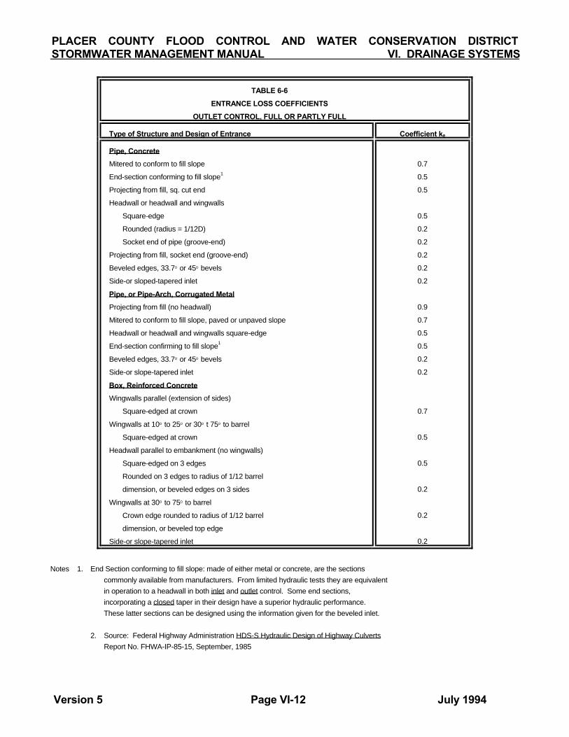
PLACER COUNTY FLOOD CONTROL AND WATER CONSERVATION DISTRICT STORMWATER MANAGEMENT MANUAL VI. DRAINAGE SYSTEMS
Version 5 Page VI-12 July 1994
TABLE 6-6
ENTRANCE LOSS COEFFICIENTS
OUTLET CONTROL, FULL OR PARTLY FULL
Type of Structure and Design of Entrance Coefficient ke
Pipe, Concrete
Mitered to conform to fill slope
End-section conforming to fill slope1
Projecting from fill, sq. cut end
Headwall or headwall and wingwalls
Square-edge
Rounded (radius = 1/12D)
Socket end of pipe (groove-end)
Projecting from fill, socket end (groove-end)
Beveled edges, 33.7° or 45° bevels
Side-or sloped-tapered inlet
Pipe, or Pipe-Arch, Corrugated Metal Projecting from fill (no headwall)
Mitered to conform to fill slope, paved or unpaved slope
Headwall or headwall and wingwalls square-edge
End-section confirming to fill slope1
Beveled edges, 33.7° or 45° bevels
Side-or slope-tapered inlet
Box, Reinforced Concrete Wingwalls parallel (extension of sides)
Square-edged at crown
Wingwalls at 10° to 25° or 30° t 75° to barrel
Square-edged at crown
Headwall parallel to embankment (no wingwalls)
Square-edged on 3 edges
Rounded on 3 edges to radius of 1/12 barrel
dimension, or beveled edges on 3 sides
Wingwalls at 30° to 75° to barrel
Crown edge rounded to radius of 1/12 barrel
dimension, or beveled top edge
Side-or slope-tapered inlet
0.7
0.5
0.5
0.5
0.2
0.2
0.2
0.2
0.2
0.9
0.7
0.5
0.5
0.2
0.2
0.7
0.5
0.5
0.2
0.2
0.2
Notes 1. End Section conforming to fill slope: made of either metal or concrete, are the sections commonly available from manufacturers. From limited hydraulic tests they are equivalent in operation to a headwall in both inlet and outlet control. Some end sections, incorporating a closed taper in their design have a superior hydraulic performance. These latter sections can be designed using the information given for the beveled inlet. 2. Source: Federal Highway Administration HDS-S Hydraulic Design of Highway Culverts Report No. FHWA-IP-85-15, September, 1985

PLACER COUNTY FLOOD CONTROL AND WATER CONSERVATION DISTRICT STORMWATER MANAGEMENT MANUAL VI. DRAINAGE SYSTEMS
Version 5 Page VI-13 July 1994
REFERENCES 1. American Society of Civil Engineers, Design
and Construction of Sanitary and Storm Sewers, Manual of Engineering Practice, #37 (W.P.C.F. Manual of Practice, No. 9) Prepared by a Joint Committee of the A.S.C.E. and the Water Pollution Control Federation, A.S.C.E., New York, New York, 1960.
2. CalTrans, Highway Design Manual, Fourth
edition with 1990 revisions. 3. Chow, Ven Te, Open-Channel Hydraulics,
McGraw-Hill, 1959. 4. City & County of Denver, Criteria for Storm
Sewer Design, Department of Public Works, Denver, Colorado, 1963.
5. Colby, Ardis V., Kenneth J. Kieker and Arnold
Lenz, Storm Drainage Practices of Thirty-two Cities, A.S.C.E. National Meeting on Water Resources Engineering. New York, New York, October 16-20, 1967.
6. Federal Aviation Agency, Airport Drainage,
Washington, D. C., 1966. 7. Federal Highway Administration, HDS-5,
Hydraulic Design of Highway Culverts, Report No. FHWA-IP-85-15, September, 1985.
8. Institute of Transportation and Traffic
Engineering, Street and Highway Drainage, Volumes 1 & 2, University of California, Berkeley, CA 1982.
9. King, H.W. and E.F. Brater, Handbook of
Hydraulics, McGraw-Hill, 1976.
10. Metcalf & Eddy, Inc., Wastewater Engineering: Collection, Treatment, and Disposal, McGraw-Hill, 1972.
11. National Association of County Engineers
Action Guide Series, Drainage Volume XIV, National Association of Counties Research Foundation, 1972.
12. Portland Cement Association, Handbook of
Concrete Culvert Pipe Hydraulics, Chicago, Illinois, 1964.
13. Rouse, Hunter, Elementary Mechanics of
Fluids, New York, New York, 1946. John Wiley and Sons, Inc.
14. Soil Conservation Service, Engineering
Division, Design of Open Channels, Technical Release No. 25, 1977.
15. Taylor, Edward H., Flow Characteristics at
Rectangular Open-Channel Junctions, Transactions, A.S.C.E., Vol 109, 1944, p.893.
PLACER COUNTY FLOOD CONTROL AND WATER CONSERVATION DISTRICT STORMWATER MANAGEMENT MANUAL VI.. DRAINAGE SYSTEMS
Version 3 Page VI-A-1 February 1994
APPENDIX 6A
FEDERAL HIGHWAY ADMINISTRATION NOMOGRAPHS
HEADWATER DEPTH FOR CULVERTS
WITH INLET CONTROL
CHARTS 1 THROUGH 13

PLACER COUNTY FLOOD CONTROL AND WATER CONSERVATION DISTRICT STORMWATER MANAGEMENT MANUAL VI.. DRAINAGE SYSTEMS
Version 3 Page VI-A-2 February 1994

PLACER COUNTY FLOOD CONTROL AND WATER CONSERVATION DISTRICT STORMWATER MANAGEMENT MANUAL VI. DRAINAGE SYSTEMS
Version 3 Page VI-A-3 February 1994
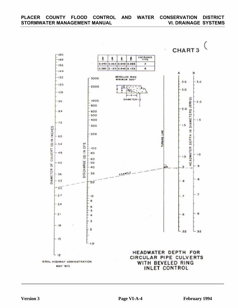
PLACER COUNTY FLOOD CONTROL AND WATER CONSERVATION DISTRICT STORMWATER MANAGEMENT MANUAL VI. DRAINAGE SYSTEMS
Version 3 Page VI-A-4 February 1994

PLACER COUNTY FLOOD CONTROL AND WATER CONSERVATION DISTRICT STORMWATER MANAGEMENT MANUAL VI. DRAINAGE SYSTEMS
Version 3 Page VI-A-5 February 1994
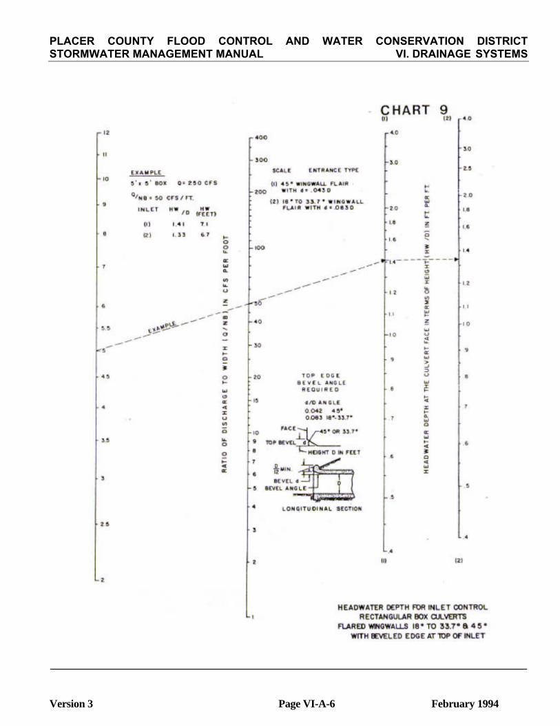
PLACER COUNTY FLOOD CONTROL AND WATER CONSERVATION DISTRICT STORMWATER MANAGEMENT MANUAL VI. DRAINAGE SYSTEMS
Version 3 Page VI-A-6 February 1994

PLACER COUNTY FLOOD CONTROL AND WATER CONSERVATION DISTRICT STORMWATER MANAGEMENT MANUAL VI. DRAINAGE SYSTEMS
Version 3 Page VI-A-7 February 1994

PLACER COUNTY FLOOD CONTROL AND WATER CONSERVATION DISTRICT STORMWATER MANAGEMENT MANUAL VI. DRAINAGE SYSTEMS
Version 3 Page VI-A-8 February 1994

PLACER COUNTY FLOOD CONTROL AND WATER CONSERVATION DISTRICT STORMWATER MANAGEMENT MANUAL VI. DRAINAGE SYSTEMS
Version 3 Page VI-A-9 February 1994

PLACER COUNTY FLOOD CONTROL AND WATER CONSERVATION DISTRICT STORMWATER MANAGEMENT MANUAL VI. DRAINAGE SYSTEMS
Version 3 Page VI-A-10 February 1994
PLACER COUNTY FLOOD CONTROL AND WATER CONSERVATION DISTRICTSTORMWATER MANAGEMENT MANUAL VII. STORAGE
detention storage except water is stored for a significantly longer period. Water may be released from retention storage after a storm has ended or it may be retained for a much longer period for other uses such as recreation, surface water supply, or groundwater recharge. 2. Instream Storage Instream storage involves the construction of an embankment across a channel so that a storage pond is formed. Instream storage affects the timing of the flood peak moving downstream. Instream storage can trap sediment and thereby improve water quality. Spillways are important with in-stream storage to pass large floods exceeding the design runoff without threatening the integrity of the embankment.
VII. STORAGE FACILITIES
A. Introduction
Storage can be an effective tool for the management of stormwater runoff. Storage lends itself to multiple land uses and is often the least costly alternative for achieving a particular flood control objective. Temporarily detaining a few acre feet of runoff can significantly reduce downstream flows and pipe and channel sizes, especially when the flood hydrograph has a rapid rise and fall. Storage can also remove sediment and debris which reduces sediment and pollutant loading on receiving waters. The use of storage to reduce flood peaks is also potentially detrimental to flooding conditions, however. Storage facilities must be adequately maintained in order to function properly. Further, storage may potentially worsen downstream conditions for events larger or smaller than a single design event, and storage provided at some locations in a basin can actually increase total watershed peak flows by causing runoff peaks to coincide with peaks from other parts of the basin. This section is concerned with the planning and design of facilities and features for providing storage in drainage systems. An
3. Off-stream Storage With off-stream storage, flows are diverted to a storage area adjacent to the stream such as an open depression, reservoir, or low lying recreational field. Flow into the off stream storage is controlled by a side channel spillway or conduit from the main channel. Water is returned to the stream at a reduced rate. Off-stream storage ponds may not remove as much sediment and, therefore, may require less maintenance. On the other hand, off-stream storage provides no benefits from sediment and debris collection.
Offstream storage requirements for flood control are typically less than those required with instream storage since only the upper portion of the instream hydrograph needs to be stored to achieve the desired effect.
B. Concepts and Definition
1. Detention and Retention Detention storage temporarily delays a portion of the inflow so that the maximum outflow is less than the maximum inflow. The storage of runoff is temporary: water stored is released soon after the maximum inflow has occurred.
4. Regional vs Local Storage Basins A distinction is made between regional and local storage basins. A regional storage basin is typically larger in scale. It is often identified in watershed master plans with the aid of a
Retention storage functions similarly to
Version 3 Page VII-1 February 1994

PLACER COUNTY FLOOD CONTROL AND WATER CONSERVATION DISTRICT STORMWATER MANAGEMENT MANUAL VII. STORAGE
hydrologic model of the total watershed. It can be incorporated into the Flood Control District's existing or proposed drainage system. It is owned and operated by the Flood Control District, although it may be joint use.
A regional basin will reduce the downstream peak flow rate and the necessary downstream conveyance capacities. A local detention basin, on the other hand, is one which will not be incorporated into the Flood Control District's existing or proposed drainage system, and is owned by an individual or organization other than the Flood Control District. Local basins will reduce the downstream peak flow rate, but may not be credited with downstream flow reduction.
C. Principles and Policies
1. Scale and Mitigation Storage is often an acceptable and effective alternative for mitigating the effects of development. The most desirable use of storage for mitigation is frequently the design and construction of a regional storage facility. Regional facilities tend to be more effective and can be constructed, operated and maintained at lower costs.
The design and construction of interim local facilities is an alternative where regional facilities are not planned. The avoidance of detrimental effects is an important concern for this alternative, however.
2. Uncertainty and Mitigation Estimates of flows and volumes are subject to significant uncertainty. For mitigation, the risk of overestimating preproject conditions is greater than the risk of underestimating. Therefore, when storage (regional, local, temporary or joint use) is to be used to mitigate downstream impacts due to increased flows generated by development of a site, the storage capacity and outlet size shall be such that the estimated pre-development peak flow rate from the site for all frequency storms up to and including the 100year shall be discounted by an . appropriate amount specified in Section D 1 a. 3. Avoiding Detrimental Effects No storage facility shall worsen conditions downstream. Any storage facility, especially a detention basin, has a potential for creating worse conditions downstream by altering the timing of peak flows in the stream and its tributaries. In order to avoid detrimental effects, the following alternative measures are suggested. - A hydrologic study of the watershed in which the basin would be sited. The downstream
5. Joint Use Storage Basin A joint use storage basin has uses in addition to flood control such as a football field, parking lot, golf course or lake. 6. Temporary Storage Basin A temporary storage basin is a local basin used to reduce downstream peak flow rates until ultimate capacities can be provided as part of a phased development. Generally the life of a temporary basin does not exceed 10 years. 7. On-site Storage The storage of water close to the points of rainfall occurrence is onsite storage. On-site storage is typically small scale and includes ponding in parking lots, property line swales, small ponds in green areas, underground tanks and infiltration trenches. 8. Channel Storage Natural stream channels provide significant storage of runoff in wide overbank areas. Additional channel storage may be induced by providing obstacles to flow and maintaining channel roughness so that the flow is deeper and possibly wider.
Version 3 Page VII-2 February 1994

PLACER COUNTY FLOOD CONTROL AND WATER CONSERVATION DISTRICTSTORMWATER MANAGEMENT MANUAL VII. STORAGE
Cash trusts held by a responsible public entity may be required to ensure maintenance of interim local detention basins, including joint use.
limit of the study would be the point beyond which changes in peak flows would not be measurable. Where they exist, watershed models supported by the local jurisdiction or the District should be used.
A maintenance district using a Community Facilities District or other acceptable public financing shall be established to operate and maintain the joint use facility. In addition, local basin can be incorporated into other features of a development as a joint use as a means of providing adequate maintenance.
- Construction of storage basins which limit outflows to the 2-year pre-development peak flow rate.
- Construction of in-stream detention basins which result in reasonably the same outflow hydrographs as previously existed for the 2-, 10-, 25- and 100-year events. 4. On-site Storage Local jurisdictions may require on-site storage for mitigation of increased runoff. Project features which can be used for incidental storage include parking lots, parks, and other common areas. However, such facilities may not be credited with the reduction in flows downstream in regional facilities.
D. Hydrologic Evaluation
The evaluation of the effects of storage on flows is the same regardless of the scale of the storage facility. The objectives of the hydrologic evaluation to determine the required storage capacity and to verify the effectiveness of the outlet design in achieving objective flows. The required capacity of a storage basin is a function of the objective outflows, design inflows, and required freeboard. Carryover and mufti-purpose storage are also factors when retention is involved.
5. Road Culverts and Embanlanents Road embankments shall be used to provide storage where appropriate. Road embankments may create incidental storage which is effective in reducing peak flows downstream. The ponding function of embankments and culverts should be considered with their planning and design and coordinated with master drainage plans. 6. Multiple Uses Storage facilities typically offer opportunities for combined use of resources. Therefore, plans for storage facilities shall routinely consider other needs, including recreation facilities, water quality and sedimentation, and wildlife habitat. 7. Maintenance Assurance Approval of interim, local storage facilities shall be conditional to assurance that the facility would be maintained in an effective condition.
A routing of the design storm inflows is required to determine the capacity for storage basins. The outflows used in the detailed routing shall be based upon hydraulic rating curves for the outlet works proposed for the basin.
Note that if the actual storage capacity is limited by topography or costs of land acquisition and construction, it may be necessary to reformulate the objective outflows.
Version 3 Page VII-3 February 1994

PLACER COUNTY FLOOD CONTROL AND WATER CONSERVATION DISTRICT STORMWATER MANAGEMENT MANUAL VII. STORAGE
a. Uncertainty in Pre-Development FlowsWhen storage is to be used to mitigate downstream impacts due to increased flows generated by development of a site, the objective flow shall be taken as the estimated pre-development peak flow rate less 10 % of the difference between the estimated pre-development and post-development peak flow rates from the site for all standard design storms ranging in frequency from the 2-year and up to and including 100-year. In no case, however, shall the objective flow be less than 90 percent of the estimated pre-development flow. Figure 7-1 presents this criterion graphically.
1. Objective Outflows Objective outflows may be clearly designated in a stormwater management plan or may be a matter of discretion for the regulating jurisdiction. They may be based on reduction of flows at the site or at downstream locations. In any case, however, the determination of objective outflows should at least consider downstream channel capacities, interactions with other storage basins, water quality, and erosion and sedimentation. Sections C.1 and C.2 (Principles and Policies) above are especially relevant to the determination of objective outflows.
Decisions and policies related to objective outflows shall be coordinated with the Flood Control District.
Version 3 Page VII-4 February 1994

PLACER COUNTY FLOOD CONTROL AND WATER CONSERVATION DISTRICTSTORMWATER MANAGEMENT MANUAL VII. STORAGE
a. Frequency The design of the outlets will be based on achieving the 2-, 10-, 25- and 100objective outflows. The event equal to 125 % of the 100-year flood will be used for spillway design where a spillway is necessary. b. Duration The duration of flood routings shall be sufficiently long for streamflows and storage levels to return to initial conditions. Runoff from storms of increasing durations shall be routed through the storage basin to determine the maximum volume required considering carryover from one period of high runoff to the next. These storms shall be based on the design storm criteria contained in the chapter on Hydrology for durations less than 24 hours. For durations greaterthan 24 hours, a historical distribution shall beused .
b. Use of Downstream Channel CapacityIf a non-damaging downstream channel capacity can be shown to exist, then objective flows at 90 % of the downstream channel capacity may be used to reduce the storage required for mitigation. For mitigation of development, it must be demonstrated that no damages occur with the proposed channel capacity. If flood control projects have been developed downstream, the design flows of these projects may be considered in determining channel capacities. If 100-year floodplains have been designated, the 100-year flow may be considered as a basis. c. Downstream Erosion Where downstream erosion is a concern the duration of erosive flow velocities for all frequency storms shall not be substantially increased unless other forms of mitigation are provided. This can be accomplished by reducing the peak outflow rate further than that required above. d. Spillway Outflow The spillway design shall attempt to decrease outflows as much as possible with the surcharge storage capacity available at the site.
3. Initial Condition
a. Spillway Design Flood All storage basins shall be assumed 100 % full at the beginning of the spillway design portion of flood routing.
b. Other Floods The storage dedicated to flood control may be assumed empty at the beginning of design flood routings except for the spillway design flood, as indicated above. Any joint-use storage shall be assumed full.
e. Outflow Control In most cases, it is desirable to design the storage to operate under hydraulic control: i. e. the hydraulics of the outlet control the outflow rates. For large regional facilities, however, it may be desirable to incorporate manual control of the outlets to achieve more effective operation when resources are limited. In no case, however, shall the spillway be manually operated. 2. Design Inflows When available, the appropriate portions of a basin master planning model will be used to model the effects of the storage facility. If a basin master planning model does not exist, the local jurisdiction or flood control district will be consulted regarding the inflow hydrograph to be used.
E. General Criteria
This section provides general criteria and guidelines for the planning and design of local and regional detention and retention basins for flood control. For simplicity, the term "storage basin" shall apply below to both detention and retention basins unless
The criteria described below apply generally to regional and local basins except as noted.
Version 3 Page VII-5 February 1994

STORMWATER MANAGEMENT MANUAL VII. STORAGE
1. Dam Safety Jurisdiction Storage basins may be subjected to the approval and inspection of California State Division of Dam Safety. The two criteria which determine their jurisdiction are the height of the dam and the total capacity of the reservoir formed by the dam. Figure 7-2 indicates the sizes of basins which are subject to the jurisdiction of California State Division of Dam Safety. If Dam Safety criteria conflict with the criteria in this chapter, the more restrictive criteria will apply. If the criteria are contradictory, then the Dam Safety Criteria apply and the contra-diction shall be noted on the appropriate plans. 2. Site A combination of topography, economics, and effectiveness generally determines the location of storage basins. Effectiveness means that the basin would achieve flood reduction goals and, further not contribute to flooding at any location during any size of flood event.
Sites for regional storage basins are generally determined by the Flood Control District and presented in the Basin Master Drainage Plans. Sites may also be designated by policy in a specific area in the Basin Master Drainage Plans. In the absence of Basin Master plans, sites for all storage facilities of any size shall be coordinated with the Flood Control District.
b. Regonal basins shall have a minimum of 2 feet of freeboard above the spillway design flood IiWL, on the emergency spillway. For basins with larger surface areas the freeboard shall be increased due to possible wave action. Also, a Seismic Seiche analysis may be required to determine necessary freeboard. b. Joint use basins shall conform to the applicable local or regional freeboard requirements. For small basins such as parking lot and tennis court basins, the freeboard requirement may be reduced.
c. Initial Conditions
(1) Spillway Design Flood All storage basins shall be assumed 100 % full at the beginning of the spillway design portion of flood routing. (2) Other Floods The storage dedicated to flood control may be assumed empty at the beginning of design flood routings except for the spillway design flood, as indicated above.
4. Outlet Works
a. hydraulic Grade Line Pressure flow closed conduits shall be designed such that the hydraulic grade line is 6 inches below the ground or street surface. In those reaches where no surface flow will be intercepted (now or in the future), a hydraulic grade line which encroaches on or is slightly higher than the ground or street surface will be acceptable. b. Partially-Full Flow Non-pressure flow closed conduit capacities shall be based on a flow depth less than 0.8 times the conduits diameter or height to avoid instable flow regimes.
3. Freeboard
a. Local and temporary basins shall have a minimum 1-foot of freeboard above the spillway design flood HWL on the emergency spillway or 2-feet of freeboard above the 100-year 13WL in the basin, whichever is more stringent.
Version 3 Page VII-6 February 1994
PLACER COUNTY FLOOD CONTROL AND WATER CONSERVATION DISTRICT

STORMWATER MANAGEMENT MANUAL VII. STORAGE
Version 3 Page VII-7 February 1994
PLACER COUNTY FLOOD CONTROL AND WATER CONSERVATION DISTRICT

STORMWATER MANAGEMENT MANUAL VII. STORAGE
c. Diameter The outlet pipe for all basins except temporary basins shall be a minimum 24" RCP for local basins and a minimum 36" RCP for regional basins. The outlet pipe or conduit shall be encased with cutoff collars designed per "Section 242. Cut and Cover Conduit Detail" of the Bureau of Reclamation's publication Design of Small Dams (8). d. Outlet Control A metered outlet structure may be necessary to provide the necessary flow attenuation for all frequency storms. "V" shaped weirs and notched weirs are preferred over other alternates because they do not plug with debris and trash as easily as other designs. e. Emergency Drawdown All storage facili-ties, including multipurpose facilities, shall draw down within 72-hours. To the extent feasible, this shall be accomplished with an ungated, gravity outlet. If this is not feasible, the facility will be equipped with an additional manually operated outlet that permits full drawdown within this time.
f. Trash Racks Trash racks shall be provided at the inlet to the basin outlet structures(s). Trash racks shall be sufficiently large that partial plugging will not adversely restrict flows reaching the outlet control. Computations shall verify that outflow is not restricted if 90 of the trash rack is effectively blocked.
Trash racks shall be designed to be readily accessible by hand or serviceable by a piece of medium sized equipment. Access must be from above the trash rack so -the loose material can be removed.
5. Inlet Structures
a. Energy Dissipator Where storm drains enter the basin, energy dissipators and/or erosion protection shall be provided. Plans must be approved by the Flood Control District before plan approval if the basin is to be operated and maintained by the Flood Control District.
Energy dissipators may be required when the inletting flow velocities exceed 5 fps. b. Invert Stabilization Where natural drainage courses or channels enter the basin some form of invert stabilization such as a reinforced concrete spillway shall be provided. 6. Emergency Spillway A spillway shall be required only when the exceedence of the design flood would result in damage to the structure or downstream damages or risk of injury or loss of life. a. Requirement An emergency spillway is required for all regional storage facilities, and all facilities storing more than 2 acre-feet of water at maximum where an embankment is used. b. Capacity All storage basin spillways shall be designed to pass a design flood equal to 125 % of the 100-year flood required by the State's Division of Safety of Dams, whichever is greater. c. Point of Discharge Spillway outflows shall be adequately conveyed to a storm drain, drainage channel, street or an established watercourse.
d. Materials Generally, all spillway structures shall be constructed of reinforced concrete. For temporary storage basins with an expected life less than 10 years the spillway
g. Anti-Vortex Devices Anti-vortex devices shall be provided where warranted. h. Depth Gage A depth gage shall be provid-ed on the basin outlet structure in order to monitor debris deposition and basin operation.
Version 3 Page VII-8 February 1994
PLACER COUNTY FLOOD CONTROL AND WATER CONSERVATION DISTRICT

STORMWATER MANAGEMENT MANUAL VII. STORAGE
may be constructed with grouted rock or other forms of approved protection designed to resist maximum design velocities. When the spillway crest is more that 3 feet above the flowline of the facility the spillway outlets into, the spillway shall be constructed of reinforced concrete.
(2) Embankment Height Basins with heights greater than or equal to 25 feet and capacity greater than or equal to 15 Ac. ft., or a capacity greater than or equal to 50 ac. ft. and a height greater than or equal to 6 feet, shall be reviewed and approved by the State's Division of Safety of Dams. (see Figure 7-1) c. Joint Use Basins Depths should be shallow and compatible with the secondary use.
The allowable depth in most cases will be site specific and shall be approved by all agencies involved.
e. Crest Elevation Generally the spillway crest shall be at or above the basin's design 100 year high water line. 7. Pool Elevation and Depth
a. Local Basins 8. Embankments a. Top width The minimum top width shall be 8 feet.
(1) 100-year Pool Elevation When feasible, the 100 year design pool elevation should be at or below existing natural ground. Generally no more than 50% of the basin's 100 year storage depth should be above existing ground (i.e., 50% or more of the 100-year minimum storage depth must be below the lowest ground outside basin). (2) 2 year Pool Elevation The necessary storage depth for debris plus the two year flow attenuation shall be below existing ground. (3) 100-year Depth The basin's maximum water depth for 100-year design should be
b. Side Slopes Basin side slopes should be of 3H: IV or flatter on the wet side and 2H: IV or flatter on the dry side. Steeper slopes may be acceptable on a case by case basis if rock lined and recommended in a soils and geotechnical report. c. Soils and Geotechnical Analysis For design of the embankment abutments and adjacent slopes, a soils and geotechnical report may be required by local jurisdictions. The report shall be prepared by an engineer with a demonstrated expertise in earth fill dam design. The report shall be reviewed and approved by the Flood Control District for regional facilities. The contents of the report are specified in Appendix B of this chapter.
(4) Exceptions When site conditions warrant and safety can be assured, the above depth requirements may be modified if the basin embankment is constructed of material, or has a solid core, which does not allow seepage or piping to occur.
9. Drainage
a. Low Flow Channel A low flow channel shall be provided from the basin inlets) to the basin outlet. The low flow channel shall be designed to carry .O1 cfs per acre of upstream watershed.
b. Regional Basins
(1) Depth Depths shall be as approved by the Flood Control District.
Version 3 Page VII-9 February 1994
PLACER COUNTY FLOOD CONTROL AND WATER CONSERVATION DISTRICT

STORMWATER MANAGEMENT MANUAL VII. STORAGE
Barriers for regional facilities shall be approved by the Flood Control District. Joint use basin fencing will be site specific and must meet the need of all agencies utilizing the basin. 12. Maintenance Strip A maintenance strip is required for regional storage facilities. Maintenance of the basin in general is
(1) Lining Where basin slopes exceed 2 % or produce erosive flow velocities the low flow channel should be protected from erosion with reinforced concrete, rock lining or other form of approved erosion protection.
(2) Joint Use basins
(a) low flow channel or conduit should be provided to conduct minor flows around the joint use facilities wherever possible. Low flow channels may not be necessary for parking lot basins or other similar joint uses. (b) The flow channel may be grass lined if there exists a maintenance program which includes mowing and maintenance of turf in good condition and velocities of flow through the various stages of discharge are low enough to be non-erosive.
The outlet structure for the basin must be readily accessible throughout the year. Maintenance strips for access to the outlet structure are located on the sides or immediate perimeter of the basin. The ideal position of the maintenance strip is along the sides of the basin . at an elevation above the outlet pipe, usually 2 to 4 feet above the bottom of the basin. The maintenance strip should be a minimum of 15 feet wide with no slopes greater than 10 % . No special paving is required for the maintenance strip. Any other roadway is considered an access road.
b. Earth Basin Floors Earth basin floors shall slope at a minimum 1.0% grade to the low flow channel and shall have a minimum grade of 1.0 % from the inlet to the outlet.
c. High Water Table In case the water table is higher than the bottom elevation of the basin, plans should consider the disposition of the water. Either a system of finger drains and a low flow channel can be. used, or some provision for a permanent water pool can be made. The contents of the permanent water pool should not be considered part of the capacity of the storage basin.
10. Sedimentation Provisions for storage of the projected sediment shall be included in the freeboard & maintenance requirements.
11. Fencing If a public safety concern exists, fencing or other protective barriers shall be provided to the satisfaction of the local jurisdiction. Similar barriers may be required for an area with a vertical drop of 36" or more.
13. Access
a. Access Road Access to any type of storage basin area shall be provided by at least one roadway from a public street or public access to the parcel upon which the basin is constructed.
b. Access Maintenance Access shall be maintained under all weather conditions.
c. Perimeter Road A 15-foot wide roadway shall be provided along the top of embankment, across the spillway and around the basin. The criteria may be modified where it can be shown the recommended top width is not necessary for structural safety and maintenance. Approval will be required by the Flood Control District for regional facilities or by the local jurisdiction for local facilities.
Version 3 Page VII-10 February 1994
PLACER COUNTY FLOOD CONTROL AND WATER CONSERVATION DISTRICT

STORMWATER MANAGEMENT MANUAL VII. STORAGE
(1) Alternative Turnarounds If access across the spillway is not provided and no other access exists, minimum 40' X 60' turn arounds may be required on both sides of the spillway.
(2) Alternatives for Joint Use If there exists adequate access for maintenance, this requirement may be amended for local, temporary or joint use basins. d. Access Ramps Access ramps shall be provided to the basin floor. A minimum of one - 15 foot wide ramp is required for local basins. Minimum of two - 15 foot wide ramps are required for regional basins.
e. Slope The maximum roadway or access ramp slope shall be 10 % .
f. Turning Radius The minimum access and roadway inside turning radius shall be 35 feet.
14. Rights-of-Way Sufficient rights-if-way shall be provided for the construction and economical maintenance of the basin(s), (including all fill and cut slopes) and shall include sufficient area to provide for an access road from a dedicated public street to the basin.
F. Alternative On-site Storage
The following suggests alternatives to dedicated, on-site flood control basins. In general, criteria have not been developed for effective on-site storage in this region. Proposals for reducing off-site flows with these methods must be reviewed case by case. 1. Hydrologic Criteria The effectiveness of on-site storage shall be evaluated using the basic hydrologic concepts and criteria for storage basins. 2. Parking Lots Storm runoff can be detained on parking lot sites by shallow basins or swales. Arrangement of areas in a parking lot to accept ponding shall be planned so that pedestrians are inconvenienced as little as possible. A 7-inch design depth is allowable for parking
3. Open Space. Parks and Recreation Fields Grassed recreational fields can be utilized for the temporary storage of the storm runoff without adversely affecting their primary function. Positive drainage toward the outflow control structure is important to avoid the prolonged entrapment of water which can cause swampy soil, growth of undesirable plants, and mosquitoes. 4. On-Site Ponds On-site ponds which have recreational uses can provide significant storm runoff storage benefits when properly planned and designed. Overflow spillways must be provided to bypass or discharge flows into floodways on the peripheries of the ponds so that safe water-storage elevations are not exceeded nor banks breached. For extremely large ponds, adequate design precautions should be taken to minimize possible shoreline erosion attributable to wind and wave action. Restricting sediment
b. Local Basins Local basins shall be covered by an adequate drainage easement or dedicated in fee title to the local jurisdiction. 15. Landscaping A landscaping plan may be required by local jurisdictions. It is recommended that top soil within the basins should be salvaged and spread on the basin slopes and invert to provide a suitable environment for future landscaping and a water supply line for future irrigation should be installed at the basin site.
Version 3 Page VII-11 February 1994
PLACER COUNTY FLOOD CONTROL AND WATER CONSERVATION DISTRICT
accumulation and water

STORMWATER MANAGEMENT MANUAL VII. STORAGE
having rolled curb configuration, can be provided to serve as storage areas for excess runoff in low-density residential neighbor-hoods. Roads having low traffic volumes and speed limits are compatible with this concept, particularly where path and walkway systems are built into the planning scheme to skirt the roadways and provide pedestrian access thereto. Swaling of roadways having good infiltration rates may provide low-cost stormwater storage and retard discharge rates in grass-lined channels. Few, if any, storm drains are required below grade. Swales and roadway shoulders must be designed and constructed with care to keep damage and maintenance to a minimum. They should be carefully designed so as not to constitute a traffic hazard. A 6 to 1 maximum slope when installed on roads with speed limits in excess of 55 kmh (35 mph) is a usual design criterion. 8. Subsurface Disposal Below-grade disposal of runoff through pervious soils may be a viable alternative to aboveground storage. Deep soil sampling should be performed to assess the feasibility of waterloading the various geological strata. Percolation tests, pumping tests, and soil sampling should provide useful data as to depth, size, and locations where subsurface disposal is practical. Levels of groundwater and the impacts, if any, on local water supply wells also effect feasibility. Dry wells can provide a means of storage as well as a significant discharge or dissipation potential in permeable soils. Provisions should be included in design, construction, and maintenance programs to minimize siltation and clogging of the permeable soil strata to avoid significant impairment of infiltration capacity. Dry well should not only extend to depths where pervious soils are present but should also be deep enough so that possible seepage downhill does not create a problem.
pollution in large ponds is of particular importance, especially when recreational use of the pond is permitted or planned. The polluting effects of roadside accumulations of salts, copper, and asbestos from brake linings, grease, oil, and heavy metals are significant if allowed to enter a storage pond. Such deleterious material should be screened out of the drainage system by interception and disposition before it reaches stormwater storage ponds. Without such precautions, water quality can deteriorate to a point where a storage pond becomes a distinct detriment to the development. 5. Road Embankments and Culverts Drainage systems are designed to utilize the roadway embankments as dams and control structures so that runoff will pond upstream of these points. The structures will normally pass small flows unimpeded, and ponding will be activated when flow rates approaching a control point exceed the pass-through rate used in the hydraulic design. Roadway embankments at control points should be stabilized and protected to minimize erosional effects of rainfall and stream flows. 6. Underground Tanks This type of on-site detention involves the underground construction of a holding tank or large size pipe as a means of providing controlled runoff from the site. This application should be limited to highly congested areas where surface ponding is prohibited due to the scarcity or high cost of available land, or areas where surface topography is not conducive to aboveground storage. Outflow control devices may consist of small gravity pipes, weirs, or proprietary devices. In some applications, pumping may be required to discharge stored runoff Overflow capabilities
7. Roadside Drainage Swales Drainage swales adjacent to roadways without curbs,
Version 3 Page VII-12 February 1994
PLACER COUNTY FLOOD CONTROL AND WATER CONSERVATION DISTRICT

STORMWATER MANAGEMENT MANUAL VII. STORAGE In some areas, lateral trenching in permeable soils may be an alternative of excess storm runoff. Perforated drain pipe or an open graded fill of rock or gravel may be used. Filter Cloth or other protection for the drain or trench must be provided to screen out migration of fine materials which can clog the voids and negate the percolation potential of the receiving soil strata. A thorough soil investigation across the site is a primary prerequisite in planning such structures. When placed in operation, underground stormwater disposal facilities can be protected by filter sheets orbags located ahead of the inlets) to trap the first flush of debris, silt and pollutants for subsequent removal by maintenance crews. Without adequate and frequent maintenance, failure of such traps may lead to flooding problems. Disposal based upon infiltration and percolation may not provide a long-term solution in as much as sediment may seal the soil interface and reduce the rate at which water enters the soils. G. Documentation
A report which documents the planning and design of storage facilities must be submitted for review in addition to information in the normal stormwater management plan.
The contents of the additional documentation are identified in a supplement to this manual.
Version 3 Page VII-13 February 1994
PLACER COUNTY FLOOD CONTROL AND WATER CONSERVATION DISTRICT

STORMWATER MANAGEMENT MANUAL VII. STORAGE
REFERENCES 1. American Society of Civil Engineers,
the National Association of Homebuilders and the Urban Land Institute, Residential Stormwater Management, 1975.
2. APWA, Urban Stormwater Management
- Special Report No. 49. 1981. 3. Chow, Ven Te, Editor-in-Chief,
Handbook of Applied Hydrology, McGraw-Hill, 1964.
4. De Groot, William, ed., Stormwater
Detention Facilities, ASCE, 1982. 5. Federal Water Pollution Control
Administration, Water Pollution Aspects of Urban Runoff, Washington, D.C., March 1969.
6. Linsley, Ray K. and Franzini, Joseph
B. Water-Resources Engineering, McGraw-Hill, 1964.
7. Task Committee on the Design of
Outlet Control Structures, Stormwater Detention Outlet Control Structures,
ASCE, 1985.
8. US Bureau of Reclamation, Design of Small Dams, USGPO, 1987.
9. US Soil Conservation Service, Earth
Dams and Reservoirs, Technical Release No. 60, August 1981.
Version 3 Page VII-14 February 1994
PLACER COUNTY FLOOD CONTROL AND WATER CONSERVATION DISTRICT

PLACER COUNTY FLOOD CONTROL AND WATER CONSERVATION DISTRICTSTORMWATER MANAGEMENT MANUAL VIII. STREAMS AND CHANNELS
3. Lined channels must be used when there are high velocities due to a reduced section or steep slopes: they may be used with subcritical or supercritical flow. Linings include concrete, stone and other permanent material. 4. Bankfull flow is the flow in a channel that creates a water surface at or near the normal ground elevation, or the tops of dikes or continuous spoil banks that confine the flow
VIII. STREAMS AND CHANNELS Open channels may have significant advantages in cost, capacity, multiple use, and potential for reducing flood peaks. This chapter provides standards and criteria for the incorporation of open channels in a drainage system, including both natural & artificial channels.
A. Definition
This chapter identifies three kinds of open channels: natural, grassed channels, and lined channels. Overlap among these categories exists, and criteria from more than one category may apply to a given channel.
1. Natural channels are characterized by irregular section, alignment, vegetative cover and bottom and side materials. Velocities are usually low in the natural channel, resulting in long concentration times and lower downstream peak flows. Natural channels often have an overbank storage capacity which also tends to decrease peak flows. Maintenance needs are low if the channel is stable. The natural channel often provides opportunities for multiple uses, including fish and wildlife habitat and recreation and has the best aesthetic qualities of the alternatives. 2. Grassed channels are characterized by a more uniform section and a vegetative cover of grass.
They are typically used where velocities are low and erosion may therefore be prevented with a cover of grass.
Grassed channels may be natural or, more often, artificial. The advantages of a grassed channel include lower cost and positive aesthetic qualities.
B. Policies
1. Natural Channels Preferred Open channel planning and design objectives are often best met by using natural, or natural-type channels. Therefore, as is stated as a policy in Chapter 2, natural channels shall be used for storm runoff whenever possible. Use of natural channels will be consistent with the floodplains and open space requirements of the area and preserve as much as possible the value of the channel for fish and wildlife habitat, recreation and aesthetics.2. Channelization Channelization of natural waterways will be avoided: channelizing usually speeds up the flow, causing greater peaks and higher drainage costs downstream.
3. 100-year Capacity Open channels should be capable of carrying the 100-year runoff (a one percent chance of occurring in any single year).
4. Alignment Open channels should follow the natural drainage paths as much as possible. 5. Channels Artificial earth channels, that is, either constructed channels or heavily modified natural channels, shall not be used for drainage because of the potential erosion and damage to those downstream.
Version 3 Page VIII-1 February 1994

PLACER COUNTY FLOOD CONTROL AND WATER CONSERVATION DISTRICT STORMWATER MANAGEMENT MANUAL VIII. STREAMS AND CHANNELS
c. Drop Structures Drop structures may be used to decrease the bed slope and to control erosion in natural streams and grassed waterways. Drop structures shall be constructed with reinforced concrete, grouted rock or gabions in accordance with best engineering practice. A low-flow notch shall be provided for drainage and, where applicable, to allow passage of fish and other aquatic life. d. Riprap and Gabions Riprap may be used to prevent damage to channel bottom and bank upstream and downstream from hydraulic structures, at bends, at bridges, and in other channel areas where erosive tendencies exist. Criteria and guidelines for riprap, grouted riprap, and gabions are presented in Chapter IX. e. Appurtenant structures The channel design shall include all structures required for proper functioning of the channel and its laterals, as well as travelways for operationand maintenance. Inlets and structures needed for entry of surface and subsurface flow into channels without significant erosion or degradation shall be included in the channel design. The design also shall provide for necessary flood gates, water-level-control devices, bays used in connection with pumping plants, and any other appurtenances essential to the functioning of channels and contributing to attainment of the purposes for which they are built. If needed, protective structures or treatment shall be used at junctions between channels to insure stability at these critical locations.
5. Compliance With FEMA StandardsWhere appropriate, channel design criteria shall comply with FEMA standards and the 100-year floodplain shall be designated.
C. Criteria
1. General
a. Water Surface Profile Open channel flow is usually non-uniform because of bridge openings, curves, and structures. Except as specified below, this requires the use of backwater computations for all final channel design work. A water surface profile must be computed for all channels and clearly shown on the final drawings. Computation of the water surface profile should use standard backwater methods, such as .the Corps of Engineers HEC-2 computer program, taking into consideration losses due to changes in velocity, drop structures, bridge openings, and other obstructions. Computations begin at a known point and extend in an upstream direction for subcritical flow and downstream for critical flow. The depth of flow in the receiving stream must be consistent with the level of event being considered. Extensive cross section data taken for flood insurance purposes may be available from the local jurisdiction or FEMA. b. Manning n Values Wherever possible, Manning n values should be based on calibrations to observed high water marks and known flows for the same or a similar location. Table 8-1 provides general guidelines for estimating n values for streams and channels in cases where observations are not available. Also see Figures 8-2 and 8-3.
Version 3 Page VIII-2 February 1994

PLACER COUNTY FLOOD CONTROL AND WATER CONSERVATION DISTRICT STORMiWATER MANAGEMENT MANUAL VIII. STREAMS AND CHANNELS
Version 3 Page VIII-3 February 1994
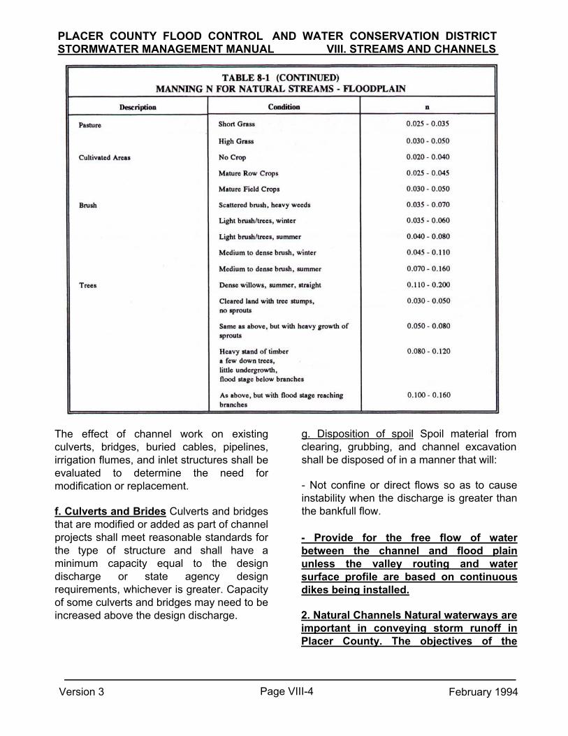
PLACER COUNTY FLOOD CONTROL AND WATER CONSERVATION DISTRICT STORMWATER MANAGEMENT MANUAL VIII. STREAMS AND CHANNELS
g. Disposition of spoil Spoil material from clearing, grubbing, and channel excavation shall be disposed of in a manner that will: - Not confine or direct flows so as to cause instability when the discharge is greater than the bankfull flow.
The effect of channel work on existing culverts, bridges, buried cables, pipelines, irrigation flumes, and inlet structures shall be evaluated to determine the need for modification or replacement. f. Culverts and Brides Culverts and bridges that are modified or added as part of channel projects shall meet reasonable standards for the type of structure and shall have a minimum capacity equal to the design discharge or state agency design requirements, whichever is greater. Capacity of some culverts and bridges may need to be increased above the design discharge.
- Provide for the free flow of water between the channel and flood plain unless the valley routing and water surface profile are based on continuous dikes being installed. 2. Natural Channels Natural waterways are important in conveying storm runoff in Placer County. The objectives of the
Page VIII-4 Version 3 February 1994

PLACER COUNTY FLOOD CONTROL AND WATER CONSERVATION DISTRICTSTORMWATER MANAGEMENT MANUAL VIII. STREAMS AND CHANNELS
stability in these channels. The criteria below are intended to provide for other purposes, such as fish and wildlife habitat and recreation.
a. Stability The main difficulties in the use of natural channels result from the effects of increased flows on the stability of the channel. Natural streams have an equilibrium in which the watershed, length, slope, width and depth of the channel, floodplain, and channel bedforms evolve in relationship with each other. This equilibrium determines the nature of the eroding, transporting, sorting,, and depositional processes. The equilibrium upset by land use changes, channelization or other modifications. Channel adjustments which typically occur as a result of increased peak discharge or increased volume of storm runoff are widening and relocation of the channel, within the floodplain.
Therefore, where it is necessary to modify a natural channel or create a new open channel to accommodate increased flows from development channel design must consider not only the effects of peak flows, but also the effects of base flow hydrologic conditions on sediment transport, channel stability, erosion control, water quality, and vegetation, wildlife and aquatic resources. In order to assure a successful design, the components of a natural system in channel improvements should be included. These,' components include a relatively narrow low flow channel to increase velocities and flow depths; a flat terrace between the low flow channel and the bank to accommodate peak flows; meander and pool and riffle sequences to accommodate sediment transport; and riparian vegetation on the terrace and shade trees on the banks to maintain lower water temperatures and discourage vegetative growth in the channel. Figure 8-1 illustrates these components.
Version 3 Page VIII-5 February 1994

PLACER COUNTY FLOOD CONTROL AND WATER CONSERVATION DISTRICT STORMWATER MANAGEMENT MANUAL VIII. STREAMS AND CHANNELS
The allowable as-built velocity in the newly constructed channel may be increased by a maximum of 20 % if irrigation is provided to establish a vegetative cover before October 15. For newly constructed channels in fine-grained soils and sands, the n values shall not exceed 0.025. The n value for channels to be modified by clearing and snagging only shall be determined by reaches according to the expected channel condition upon completion of the work.
All channel construction and modification including clearing and snagging shall be according to a design that can be expected to result in a stable channel that can be maintained at reasonable cost.
Vegetation, riprap, revetments, linings, structures, or other measures shall be used if necessary to insure stability. Characteristics of a stable channel are:
o The channel neither aggrades nor degrades beyond tolerable limits. o The channel banks do not erode to the extent that the channel cross section is changed appreciably at critical sections.
(2) Aged condition Bankfull flow or design discharge, whichever is larger, except that it is not necessary to check stability for discharge greater than the 100-year frequency. b. Capacity Channel and overbank capacity shall be adequate for 100-year fully-developed runoff if possible. Design flows shall be determined by the basin master planning model, if available. The water surface profile or hydraulic gradeline for design flow shall be determined with HEC-2. The n value shall reflect the expected vegetation at the level of maintenance prescribed in the operation and maintenance plan. e. Velocity Permissible velocities are shown in Table 8-2. In addition, velocities for any section shall not exceed critical velocity for that section.
o Excessive sediment bars do not develop.
o Gullies do not form or enlarge because of the entry of uncontrolled surface flow to the channel.
To evaluate the stability of a natural channel, it is generally necessary to estimate velocities under design conditions and to assess the bed and bank material for erosion potential with the velocities indicated. Velocities computed in the backwater analysis are suitable for this evaluation.
Channels must be stable under conditions existing immediately after construction (as-built condition) and under conditions existing during effective design life (aged condition). Channel stability shall be determined for discharges under these conditions as follows:
d. Supercritical Flow Supercritical flow usually does not exist in natural channels and frequent checks should be made during the course of the backwater computations to insure that the computations do not reflect supercritical flow. (1) As-built condition Bankfull flow, design
discharge, or 10-year-frequency flow, which-ever is smallest, but not less than 50 percent of design discharge.
Version 3 Page VIII-6 February 1994

PLACER COUNTY FLOOD CONTROL AND WATER CONSERVATION DISTRICT STORMWATER MANAGEMENT MANUAL VIII. STREAMS AND CHANNELS
2, 8,9,10,15,17,20,21. Many of these refer-ences are available in the Placer County Flood Control District library. h. Environmental Features Environmental features may be desirable or necessary to provide for or enhance multiple uses or to mitigate for significant adverse impacts. Criteria and guidelines for environmental features are beyond the scope of this manual but may be found in references 2,8,9,10,12,15,17,20,21. Many of these ref-erences are available in the Placer County Flood Control District library. 3. Grassed Channels Grassed channels feature a uniform cover of grass to protect the channel from erosion where low velocities make this possible. Grass lined channels may be a desirable alternative because of its stability and aesthetic qualities. The criteria specified below also may apply to natural
e. Storage Effects on Downstream FlowsFilling of the flood fringe reduces valuable storage capacity and tends to increase downstream runoff peaks. The evaluation of storage capacity and effects of proposed changes shall be evaluated using appropriate engineering standards and guidelines. Acceptable alternatives includes use of Modified Puls or a widely accepted unsteady-flow model. f. Drop Structures Drop structures may be used at regular intervals to decrease the bed slope and to control erosion. g. Other Improvements Improvements to natural channels to provide more capacity or protect the channel from erosion, other than those listed above, are beyond the scope of this manual. Criteria and guidelines for these improvements may be found in references
Page VIII-7 Version 3 February 1994

PLACER COUNTY FLOOD CONTROL AND WATER CONSERVATION DISTRICT STORMWATER MANAGEMENT MANUAL VIII. STREAMS AND CHANNELS
channels where appropriate.
b. Design Velocities Maximum permissible velocities for various grasses and soils are presented in Table 8-3. Design velocities for all linings should not fall below 2 fps for the 10-year runoff to minimize sediment depositional problems. If the natural channel slope would cause excessive velocity, drop structures, checks, riprap, or other suitable channel protection shall be employed. c. Roughness Coefficients The hydraulic roughness of grass lined channels depends on the length of cutting, if any, the type of grass, and the depth of flow. Roughness coefficients are determined using Figure 8-2 based on the retardance values of Table 8-4.
a. Capacity
(1) Uniform Section and Slope The capaci-ty for a grassed channel with uniform section and slope may be calculated at normal depth using Manning's formula with an appropriate n value.
(2) Irregular Section and SIM The capacity for a grassed channel with an irregular section or slope must be calculated with a backwater model as described above.
(3) Overbank Flows When the channel slope is less than 0.01 feet/feet, overbank flow may be allowed if such flow will not cause excessive erosion or damage to structures.
Page VIII-8 Version 3 February 1994

PLACER COUNTY FLOOD CONTROL AND WATER CONSERVATION DISTRICT STORMWATER MANAGEMENT MANUAL VIII. STREAMS AND CHANNELS
Erosion control cut-off walls are usually of reinforced concrete, approximately 8 inches thick and from 18 inches to 2 feet deep, extending across the bottom of the channel. They can be shaped to fit a slightly sloped bottom to help direct water to the low-flow channel or to an inlet.
d. Grass Lining The grass lining used should be capable of surviving without irrigation, and have a thick root structure for keeping the bank soils in place. e. Planting Considerations The most critical time in successfully installing grassed waterways is when vegetation is being established. Special protection such as mulch anchoring, straw or hay bale dikes, or other diversion methods are warranted at this critical period. Supplemental irrigation may also be warranted. The vegetation should be rimed so plants will be established before flows occur in the channel.
Since grass will not grow under a bridge; a cutoff wall should be used at the downstream edge of the bridge, or the area under the bridge deck should be stabilized with soil-cement.i. Drop Structure Drop structures may be necessary to maintain an appropriate channel slope. Riprap or gabions shall be used at drop structures to prevent erosion downstream.
f. Irrigation Where irrigation water is available for establishment and maintenance, dense, sod-forming perennial grass can be used that will permit higher velocities compared with bare earth. Where no irrigation water is available, a longer establishment period is required for perennial cover. Annual grasses are generally shallow-rooted so safe velocities cannot exceed those for bare earth and drop structures may be required. g. Low-Flow Channel A low-flow channel shall be used and shall provide a capacity of 0.5 to 1.0 percent of the major design flow. The low-flow channel shall be protected from erosion with rock lining. Flows must enter the low-flow channel without flowing parallel to the channel, or bypassing the inlets. h. Cut-off Walls The use of cut-off walls at regular intervals in a grassed channel is desirable for erosion control since a small level of erosion is otherwise unavoidable. Cut-off walls are also useful in containing the
j. Design Sloes Grass lined channels function well with slopes from 0.2 to 0.6 percent. Steeper slopes shall be reduced with drop structures. k. Channel Cross Sections The channel shape may be any type suitable to the location and to the environmental conditions provided they meet all other criteria. 1. Side slopes The minimum maintainable side slope is 2:1. Flatter slopes are more desirable.
m. Alignment Sharp curves shall not be used. Centerline curves should not have a radius of less than twice the design flow top width, but not less than 100 feet. n. Freeboard Required freeboard varies according to the size of the channel and stability of proposed improvements. In general, a minimum freeboard of 3 feet is required beneath bridge and utility crossing and where a levee contains the flow. Exceptions will be allowed when justified.
Version 3 Page VIII-9 February 1994

1. The permissible velocities are for dense stands of grasses. The species chosen must be compatible with climatic and soil conditions. Check with the local Soil Conservation Service office for planting mix recommendations.
2. For channels with flow velocities greater than 5 fps, a
synthetic erosion liner, jute, or anchored straw mattings are required for seeded or sprigged plantings. Sod may be used without cover but requires irrigation.
3. Not recommended. Use grade control structures or other
types of lining. 4. Requires irrigation, but tolerates flooding and standing
water.
Version 3 Page VIII-10 February 1994
PLACER COUNTY FLOOD CONTROL AND WATER CONSERVATION DISTRICT STORMWATER MANAGEMENT MANUAL VIII. STREAMS AND CHANNELS

Note: A stand is considered "good" if 75 percent of the ground is covered by the plants. Reduce retardance one group for 50 percent ground cover.
o. Depth The maximum design depth of flow is 4.0 feet.
The watershed above the channel must be treated to prevent sheet and rill erosion to keep sediment from damaging the vegetation. 4. Lined Channels Lined channels or channel segments may be used where natural or grassed channels provide inadequate capacity given space constraints or where erosion is a problem.
p. Bottom width The bottom width shall be at least 6 to 8 times the depth of flow, but shall not exceed 100 feet. g. Maintenance A maintenance program shall be established to maintain waterway capacity, vegetative cover, and the outlet. Vegetation damage must be repaired promptly.
Version 3 Page VIII-11 February 1994
PLACER COUNTY FLOOD CONTROL AND WATER CONSERVATION DISTRICT STORMWATER MANAGEMENT MANUAL VIII. STREAMS AND CHANNELS

a. Roughness Coefficients Roughness coefficients for lined channels are:
e. Freeboard The minimum freeboard for lined waterways or outlets shall be 0.25 ft above design high water in areas where erosion-resistant vegetation cannot be grown adjacent to the paved side slopes. No freeboard is required if vegetation can be grown and maintained.
b. Design Velocities Maximum design velocity shall be as shown in Figure 8-4. Except for short transition sections, velocities at or near critical should be avoided. Velocities exceeding critical shall be restricted to straight reaches.
f. Lining thickness thickness shall be:
Minimum lining Waterways or outlets with velocities exceeding critical shall discharge into an energy dissipator to reduce velocity to less than critical. c. Cross Section The cross section shall be triangular, parabolic, or trapezoidal. Cross sections made of monolithic concrete may be rectangular. d. Side slope The steepest permissible side slopes, horizontal to vertical, shall be as shown in Table 8-6:
Concrete ………….4 in. (In most problem areas,minimum thickness shall be 5 in. with welded wire fabric reinforcing.) Rock riprap........... Maximum stone size plus thickness of filter or bedding Flagstone ………..4 in., including mortar bed g. Related structures Side inlets, drop struc-tures, and energy dissipators shall meet the hydraulic and structural requirements for the site. h. Filters or bedding Filters or bedding shall be used to prevent piping. Drains shall be used to reduce uplift pressure and to collect
Version 3 Page VIII-12 February 1994
PLACER COUNTY FLOOD CONTROL AND WATER CONSERVATION DISTRICT STORMWATER MANAGEMENT MANUAL VIII. STREAMS AND CHANNELS

thickness of the lining at a uniform spacing in the range of 10 to 15 ft. Provide for uniform support to the joint to prevent unequal settlement.
water, as required. Filters, bedding, and drains shall be designed according to generality accepted. Weep holes may be used with drains if needed.
1. Rock riprap or flay-stone Stone used for riprap shall be dense and hard enough to withstand exposure to air, water, freezing, and thawing. Flagstone shall be flat for ease of placement and have the strength to resist exposure and breaking. m. Maintenance Provisions must be made, for timely maintenance to insure that lined waterways function properly. n. Supercritical Flow Criteria (1) Curvature It is generally not possible to have any curvature in a supercritical channel. (2) Stability Flow at Froude numbers near 1 is unstable and should be avoided. Careful attention must be taken to insure against excessive oscillatory waves which may extend down the entire length of the channel from only minor obstructions upstream. The design must take care to insure that hydraulic jumps do not form.
i. Concrete Concrete used for lining shall be proportioned so that it is plastic enough for thorough consolidation and stiff enough to stay in place on side slopes. A dense durable product shall be required. Specify a mix that can be certified as suitable to produce a minimum strength of at least 3,000 lb/in.2. Cement used shall be Portland cement. Types I, II, or if required, Type IV or V. Aggregate used shall have a maximum size of 1-1/2 in.
FIGURE 8-4 VELOCITY VS DEPTH OF FLOW
(3) Cross Section There shall be no diminution of wetted area cross section at bridges or culverts. Freeboard shall be adequate to provide a suitable safety margin, the safety margin being at least 2 feet or an additional capacity of approximately one-third of the design flow. (4) Linings All channels carrying supercritical flow shall be lined with continuously reinforced concrete linings, the reinforcing being continuous both longitudinally and latterally.
j. Mortar Mortar used for mortared in-place flagstone shall consist of a workable mix of cement, sand, and water with a water-cement ratio of not more than 6 gallons of water per bag of cement. k. Contraction joints Contraction joints in concrete linings, if required, shall be formed transversely to a depth of about one-third the
Version 3 Page VIII-13 February 1994
PLACER COUNTY FLOOD CONTROL AND WATER CONSERVATION DISTRICT STORMWATER MANAGEMENT MANUAL VIII. STREAMS AND CHANNELS

FIGURE &3
VALUES OF N FOR RIPRAP LINED CHANNELS, D50 SIZE VS DEPTH OF FLOW
Version 3 Page VIII-14 February 1994
PLACER COUNTY FLOOD CONTROL AND WATER CONSERVATION DISTRICT STORMWATER MANAGEMENT MANUAL VIII. STREAMS AND CHANNELS

The linings must be protected from hydrostatic uplift forces which are created by a high water table or momentary inflow behind the lining from localized flooding. Generally a perforated underdrain pipe will be required under the lining and designed to be free draining. Imperfections at joints may rapidly cause a deterioration of the joints, in which case a complete failure of the channel can readily occur. In addition, high velocity flow entering cracks or joints creates an uplift force which can damage the channel lining. The roughness of lined, supercritical channels is a particularly critical element in their performance. The construction of supercritical channels must be rigorously inspected to insure that the design roughness is obtained. Because of field construction limitations the designer should not use a Manning n roughness coefficient any lower than 0.013 for a welltroweled concrete finish. (5) Anchorage of Crossings Bridges or other structures crossing the channel must be anchored satisfactorily to withstand the full dynamic load which might be imposed upon the structure in the event of major trash plugging.
(3) Depth The depth of flow at the design discharge will be between 3 to 4 feet deep insofar as reasonably practical. (4) Bottom Width The bottom width shall be at least 6 to 8 times the depth of the flow insofar as reasonably practical. (5) Low Flow Channel Low flow channels (trickle channels or underdrain pipes) are required to prevent standing water 'in the channel. (6) Bottom Width The bottom width shall be at least 6 to 8 times the depth of the flow insofar as reasonably practical.
o. Subcritical Flow Criteria
(1) Radius of Curvature Generally centerline curves should not have a radius of less than twice the design flow top width, but not less than 100 feet. (2) Freeboard Bridge deck bottoms and utility crossings may control the freeboard. Where they do not, a minimum freeboard of 2 feet should be allowed.
Version 3 Page VIII-15 February 1994
PLACER COUNTY FLOOD CONTROL AND WATER CONSERVATION DISTRICT STORMWATER MANAGEMENT MANUAL VIII. STREAMS AND CHANNELS

REFERENCES
1. Agricultural Research Service, Stability Design of Grass- Lined Open Channels, Agriculture Handbook Number 667, 1987.
2. American Fisheries Society, Stream
Obstruction Removal Guidelines, 1983. 3. American Society of Civil Engineers
Design and Construction of Sanitary and Storm Sewers Manual of Engineering Practice, No-37, (W.P.C.F. Manual of Practice, No. 9) Prepared by a Joint Committee of the American Society of Civil Engineers and the Water Pollution Control Federation, American Society of Civil Engineers, New York, NY, 1960.
4. Chow, Ven Te, Open-Channel Hydraulics, McGraw-Hill, 1959. 5. City & County of Denver, Criteria for Storm Sewer Design, Department of
Public Works, Denver, Colorado, 1963. 6. Colby, Ardis V., Kenneth J. Kieker and
Arnold Lenz, Storm Drainage Practices of Thirty-two Cities, A.S.C.E. National Meeting on Water Resources Engineering. New York, NY, October 16-20, 1967.
7. Federal Aviation Agency, Airport Drainage, Washington, D.C., 1966.
8. Gray, Donald H, and Andrew T. Leiser,
Biotechnical Slope Protection and Erosion Control, Van Nostrand Reinhold, 1982.
16. National Association of County Engineers Action Guide Series, Drainage Volume XIV, National Association of Counties Research
14. Metcalf & Eddy, Inc., Wastewater Engineering: Collection. Treatment. and Disposal, McGraw-Hill, 1972.
15. Ministry of Environment, Stream
Enhancement Guide, Canada, March, 1980.
13. King, Horace W. and Ernest F. Brater, Handbook Hydraulics, McGraw-Hill, 1976.
10. Heyson, James R., et al, Environmental Features for Streamside Levee Project, US Army Corps of Engineers Waterways Experiment Station, Report E-85-7, 1985.
11. Institute of Transportation and Traffic
Engineering, Street and Highway Drainage, Volumes 1 & 2 University of California, Berkeley, California, 1982.
12. Jackson, William, ed., Engineering
Considerations in Small Stream Management, American Water Resources Association Bulletin, Vol 22, No. 3, 1986.
9. Henderson, Jim E., and F. Douglas Shields, Environmental Features for Streambank Erosion Projects, U.S. Army Corps of Engineer Waterways Experiment Station, Report E-84-11, 1984.
Version 3 Page VIII-16 February 1994
PLACER COUNTY FLOOD CONTROL AND WATER CONSERVATION DISTRICT STORMWATER MANAGEMENT MANUAL VIII. STREAMS AND CHANNELS

17. Nunally, Nelson R. and F. Douglas
Shields, Incorporation of Environmental Features in Flood Control Channel Project, U.S. Army Corps of Engineers Waterways Experiment Station, Report E-85-3, 1987.
18. Portland Cement Association, Handbook
of Concrete Culvert Pipe Hydraulics, Chicago, Illinois, 1964.
19. Rouse, Hunter, John Wiley and Sons,
Inc., Elementary Mechanics of Fluids, New York, New York, 1946.
20. Schiechtl, Hugo, Bioengineering For
Land Reclamation and Conservation, University of Alberta Press, 1980.
21. Shields, F. Douglas,
Environmental Features for Flood Control Channel, U.S. Army Corps of Engineers Waterways Experiment Station, Report E-82-7, 1987.
22. Soil Conservation Service,
Engineering Division, Design of Open Channels, Technical Release No. 25, 1977.
23. Taylor, Edward H., Flow
Characteristics at Rectangular Open-Channel Junctions, Transactions A.S.C.E., Vol. 109, 1944, p. 893.
24. Walesh, Stuart, Urban Surface Water Management, John Wiley & Sons, 1989.
Version 3 Page VIII-17 February 1994
PLACER COUNTY FLOOD CONTROL AND WATER CONSERVATION DISTRICT STORMWATER MANAGEMENT MANUAL VIII. STREAMS AND CHANNELS

IX. EROSION AND SEDIMENTATION quantities eroded from land that is cropped under specified conditions to that which is eroded from clean-tilled fallow under identical slope and rainfall conditions. A. Purpose
This chapter provides guidelines for evaluating erosion potential, sediment yield, and sediment retention.
P = the supporting consideration practice factor (strip cropping, contouring, etc.). For straight-row farming P = 1.0.
Values for these parameters and a detailed description of the Universal Soil Equation is provided in the paper by Wischmeier, W.H., and Smith, D.D., "A Universal Soil Loss Equation to Guide Conservation Farm Planning," 7th International Congress of Soil Science, Madison, 1960.
2. Gully Erosion Gully development is usually associated with severe climatic events, improper land use, or changes in stream base levels. During the significant gully activity, the sediment produced and delivered to downstream locations is found in regions of moderate to steep topography having thick soil mantles. The total sediment outflow from eroding gullies, though large, is usually less than that produced by sheet erosion. A field study of gully activity in several locations throughout the United States has resulted in the tentative relationship.
B. Erosion
1. Sheet Erosion Sheet erosion is the wearing away of a thin layer of the land surface. The Universal Soil Loss Equation was developed to model sheet erosion.
E = RKLSCP
where
E = the average annual loss, in tons per acre: R = a factor expressing the erosion
potential of average annual rainfall;
K = the soil erodibility factor and represents the average soil loss, in tons per acre per unit of rainfall factors, R, from a soil in cultivated continuous fallow, with a standard plot length and % slope arbitrary selected as 72.6 feet and 9% respectively.
S and L = the topographic factors for adjusting the estimate of soil loss for specific land gradient (S) and length of slope (L) .
C = the cropping management factor and represents the ratio of the soil
Page IX-1
PLACER COUNTY FLOOD CONTROL AND WATER CONSERVATION DISTRICTSTORMWATER MANAGEMENT MANUAL SEPTEMBER 1, 1990
[9-1]

R = O.15A.49S.14P.74E [9-2] straightening and realigning of channels and, and changes in flow regimes.
where
Streambed erosion can initiate downcutting cycles in tributary channels and gullies because of the lowering of the base level.
R = is the average annual gully head advance, in feet A = is drainage area, in acres, S = is slope of approach channel, in %, P = is annual summation of rainfall, in inches, from rains equal to or greater than 0.5 inches/24 hours, E = is the clay content of eroding soil profile, as
a. Evaluation For channels in noncohesive sediments, Lane's relationship can be used qualitatively to predict the erosive channel conditions.
QS = Gsds
a percentage of weight. where
Q = is stream discharge, s = is longitudinal slope of stream channel,
The United States Department of Agriculture and Soil Conservation Services has devised an equation for the solution of field design problems involving gullies. This equation is:
is bed sedimentdischarge,
ds = is particle diameter of bed material
Quantitative estimate of channel erosion or deposition rates are obtained from the time sequence comparisons of surveyed cross sections, from maps, aerial photographs, and historical records. Predictions of channel changes are based on erosion or deposition rates when future changes in the flow regime are expected, rough estimate of scow or fill can be obtained from sediment discharge formulas (Lane and Borland, 1951; Einstein, 1950; Cotley and Hembree, 1955), the use of principles of fluvical morphology (Leopold and Maddock, 1953). The use of Regime theory (Blench, 1957) or
R = 1.5A.46P.2
where
R and A are defined in Equation 9-2 and
P = the summation of 24-hour rainfall totals of 0.5 inch or more occurring during the time period, connected to an average annual basis, in inches.
I. Segiman
3. Channel Erosion Stream bank erosion is often caused by the clearing of protective cover from banks, from the
PLACER COUNTY FLOOD CONTROL AND WATER CONSERVATION DISTRICTSTORMWATER MANAGEMENT MANUAL SEPTEMBER 1, 1990
Gs =
[9-3]
[9-4]

If the riprap size, d50, computed for bends is less than 10 percent greater than the riprap size d50 for straight channels, use the straight channel size. If greater than 10 percent use larger size riprap d50 in the bends. Use no more than two sizes on any channel. (b) Size The following procedure determines a design stone size that is stable under design flow conditions. It is from the National Cooperative Highway Research Program Report No. 108, entitled "Tentative Design Procedure for Riprap-Lined Channels." It is based on the tractive force method and covers the design of riprap in two basic channel shapes, trapezoidal and triangular. The procedure is for the uniform flow in channels and is not to be used for design of riprap deenergizing devices immediately downstream from such high velocity devices as pipes and culverts. The procedure assumes that the channel is already designed and the remaining problem is to determine the riprap size that would be stable in the channel. The n value for design is estimated by estimating a riprap size and then determining the corresponding n value for the riprapped channel from Figure 9-1.
other methods that consider the forces exerted on the stream boundaries (Lane, 1955). b. Control Alternatives
(1) Ordinary Riprap
Riprap is a layer of loose rock or aggregate placed over an erodible surface to protect the soil surface from the erosive forces of water. Riprap is placed at soil-water interfaces where soil conditions, water turbulence and velocity, expected vegetative cover and groundwater conditions may cause erosion at design flow conditions. Locations that may require riprap are storm drain outlets, channel banks and/or bottoms, roadside ditches, drop structures and shorelines. (a) Design Discharge The minimum design storm discharge for channels and diversions shall be the peak discharge from a 10 year frequency rainfall event based upon ultimate development of the watershed. The design stone size is the d50 or median stone diameter which is defined as the stone size which is exceeded by 50 percent of the mixture by weight. Diameter of the largest stone shall be 1.5 times the design stone size, d50 .
Page IX-3
PLACER COUNTY FLOOD CONTROL AND WATER CONSERVATION DISTRICTSTORMWATER MANAGEMENT MANUAL REVISION 1 MARCH 1992

PLACER COUNTY FLOOD CONTROL AND WATER CONSERVATION DISTRICT STORMWATER MANAGEMENT MANUAL REVISION 1 MARCH 1992
Figure 9-1 is based on the following equation: n = 0.0225 (d50)1/6
[9-5]
reasonable agreement, another trial must be made.
4. For channels with bends, calculate the ratio Bs/Ro, where Bs is the channel surface width and - Ro is the radius of the bend. Use Figure 9-4 and find the bend factor, FB. Multiply the d50 for straight channels by the bend factor to determine riprap size to be used in bendsbends. If the d50 for the bend is less than 1.1 time the d50 for the straight channel, then the size for straight channel may be used in the bend, otherwise the larger stone size calculated for the bend shall be used. The riprap shall extend across the full channel section and shall extend upstream and downstream from the ends of the curve a distance equal to five times the bottom width.
where
n = Mannings roughness coefficient d50 = Median stone diameter, inches When the channel dimensions are known the riprap can be designed (or an already completed design may be checked) as follows:
Trapezoidal Channels 1. Compute the ratio of the wetted
perimeter to hydraulic radius, P/R. 2. Use Figure 9-2 with Sb,Q, and P/R
to find median riprap diameter, dso, for straight channels.
3. Use Figure 9-1 to find the actual n
value corresponding to the d50 from step 2. If the estimated and actual n values are not in
Page IX-4

PLACER COUNTY FLOOD CONTROL AND WATER CONSERVATION DISTRICT STORMWATER MANAGEMENT MANUAL REVISION 1 MARCH 1992
Page IX-5

PLACER COUNTY FLOOD CONTROL AND WATER CONSERVATION DISTRICTSTORMWATER MANAGEMENT MANUAL SEPTEMBER 1. 1990
Page IX-6

PLACER COUNTY FLOOD CONTROL AND WATER CONSERVATION DISTRICT STORMWATER MANAGEMENT MANUAL SEPTEMBER 1, 1990
Page IX-7

the riprap when either of the following conditions exist: (1) Riprap is not well graded down to
the one inch size particle.
PLACER COUNTY FLOOD CONTROL AND WATER CONSERVATION DISTRICT STORMWATER MANAGEMENT MANUAL REVISION 1 MARCH 1992
The limit shall also be from the toe of the bank up to the maximum high water elevation or to a point where vegetation can be established. Where there is no paving or riprap on the bottom of the channel, the riprap shall extend at least 1.5 times the maximum stone size or minimum of 1.0 foot below the channel bottom. (d) Thickness The riprap layer shall be a minimum of 1.5 times the maximum stone size but not less than six inches. (e) Gradation Riprap shall be well graded down to the one-inch size particle. Well graded is herein defined as a mixture composed of primarily the larger stone but with a mixture of other sizes to fill the progressively smaller voids.
5. Use Figure 9-5 to determine maximum stable side.slope of riprap surface.
Triangular Channels
1. Enter Figure 9-3 with Sb, Q and Z and find the median riprap diameter, d50, for straight channels.
2. Enter Figure 9-1 to find the actual n
value. If the estimated and actual n values are not in reasonable agreement another trial must be made.
3. For channels with bends, see
step 4 under Trapezoidal channels.
The riprap size to be specified on the plans shall be the maximum stone size in the mixture which shall be 1.5 times the d50. The thickness of the riprap layer is 1.5 times the maximum stone size, but not less than six inches. Freeboard shall be added to the channel depth and shall be not less than 0.2 times the depth of flow or 0.3 feet, whichever is greater. (c) Limits of Riprap The upstream limit is from the point of curvature a distance equal to 5 times the channel bottom width. Downstream, the limit shall be from the point of tangency a distance equal to 5 times the channel bottom width.
Stone for riprap shall be field stone or uneven quarry stone of approximately rectangular shape. The stone shall be hard and angular. Individual stones shall have a specific gravity of at least 2.5. The stone will not disintegrate on exposure to water or weathering. (f) Filter Layer A filter layer of material shall be placed between the channel bottom.and riprap to prevent soil movement into and through
Page IX-8

PLACER COUNTY FLOOD CONTROL AND WATER CONSERVATION DISTRICT STORMWATER MANAGEMENT MANUAL SEPTEMBER 1. 1990
or larger shall not be dumped directly onto the cloth. A 4 inch minimum thickness of gravel shall be placed on the cloth prior to placement of the riprap. Any rips or holes in the cloth shall be repaired by placing another piece of cloth over the tear or hole. Overlap ends of cloth a minimum of one foot.
(h) Maintenance Inspect riprap periodically especially after heavy storms. Note loss or displacement of riprap and replace as necessary. Check for sediment buildup in riprap indicating a tear in filter and make all necessary repairs. (2) Grouted Riprap Grout may be used to tie the individual rock pieces together, providing a monolithic mass. It also permits the use of smaller sized rock. The grout may be a weak mix with a 28-day strength of at least 2,000 psi. The grout should penetrate into the riprap mass. A veneer within the top few inches of the riprap should be avoided. It is generally more effective to have a rough surface with portions of the rock particles projecting out from the grout surface. The projecting rocks should be cleaned with a wet broom after completing the placement of the grout. Cracking of the grouted riprap will occur with settlement and frosty however, this does not affect appearance or function.
(2) Soil layer below riprap is sand-sized or finer with a plasticity index, PI, less than 10.
Filter shall be a layer of plastic filter cloth or properly graded layer of sand, gravel or stone. The plastic filter cloth shall be woven of polypropylene monofilament yarns or equal cloth manufactured expressly for this use. Aggregate filter shall conform to the following criteria: d15 riprap <5 and d15 filter <5 d85 filter d85 base d15 = size of particle which
15% is finer by weight d85 = size of particle which
85% is finer by weight base = soil under filter
(g) Placement Subgrade for riprap or filter shall be prepared to the lines and grades shown. Fills shall be compacted to the density of adjacent undisturbed material. Stone for filter or riprap may be placed to the required thickness and limits by equipment or hand. Placement of riprap or filter shall be in one full operation to the full course thickness. .Avoid displacement of underlying materials. If a filter cloth is to be used, riprap that is 12 inches
Page IX-9
_ _

PLACER COUNTY FLOOD CONTROL AND WATER CONSERVATION DISTRICT STORMWATER MANAGEMENT MANUAL SEPTEMBER 1. 1990
2. Policy - Sediment basins will be used to trap sediment originating from construction sites where physical conditions or land ownership preclude adequate treatment of the sediment source by the installation of permanent erosion control measures. Sediment basins will be required where natural streams enter underground storm drainage systems or improved channel reaches. The minimum design trap efficiency shall be 60 percent.
Sediment retention structures may be single or multiple purpose flood control structures and shall contain the following features: a. Excavated basin and/or compacted embankments. b. Inlet channels to allow flows to enter the basin. c. Baffles to spread runoff throughout basin. d. Pipe riser as the principle spillway.
Attention to aesthetics should be given with grouting of riprap in developed areas to insure a reasonably acceptable appearance. (3) Gabions Side slopes of 1:1 are satisfactory for channel banks. The gabions should be keyed into both banks for drops to prevent flanking, and downstream cutting should be considered. The hydraulic roughness of gabions is usually about 0.035; however, for use in drops larger stones may be used at the surface to increase the roughness to dissipate additional hydraulic energy. (4) Vegetation Vegetation may be used to protect streambank from erosion. Use of grass is discussed in Chapter VIII. References 2, 3, 6, 9, 10 and 11 discuss other alternatives.
C. Sedimentation and sediment Retention Structures 1. Purpose - Sediment retention basins are needed to preserve the capacity of downstream waterways and to protect underground storm drainage facilities. The basins are designed to collect and store portions of the sediments or debris being carried by runoff. They work by slowing the velocity of the runoff and allowing suspended soil particles to settle by gravity.
e. Basin dewatering device. f. Emergency spillway.
g. Outlet protection or direct hookup to
storm drain -system.
h. Access road and ramp for basin clean-out.
i. Fencing and other safety for public safety.
Page IX-10

PLACER COUNTY FLOOD CONTROL AND WATER CONSERVATION DISTRICT STORMWATER MANAGEMENT MANUAL SEPTEMBER 1. 1990
The total sediment yield is determined by the equation,
3. Criteria
a. Size Distribution of Sediments The particle size distribution of the stream bed soils and principal sediment sources shall be determined by sampling and laboratory analysis.
b. Minimum Basin Storage Capacity Determine minimum storage capacity of reservoir from appropriate curve on Figure 9-1 for the design trap efficiency.
c. Area and Depth of Pondinq For particle to be trapped, the basin travel time must be equal to or greater than the particle settling time as shown on Table 9-1.
Unless otherwise required by the State Department of Fish and Game, the minimum sediment basin depth shall be based upon a settling velocity of the median grain size of the sediments or 60 microns, whichever is less. 4. Gross Erosion and Sediment Delivery Ratio The average annual erosion quantity from sloping uplands shall be computed by means of the Universal Soil Loss Equation (LISLE). The estimated quantities from stream bank and gully erosion should .be-added to the LISLE value.
Y = E (DR)
where
Y = Sediment Yield (Tons/unit area/year)
E = Gross erosion, tons/unit area/year DR = Sediment Delivery Ratio, Figure 9-2
5. Basin Clean Out Interval The basin clean out interval shall be based upon basin capacity (C) less the volume of water required to produce the settlement time and is computed as follows:
I = (3630C-AD) / (YWS) [9-6]
where
I = Clean out interval in years C = Capacity, acre-inches A = Area of Basin, sq. ft. D = Depth of Flow, ft. Y = Sediment yield, tons/acre/year WS = Submerged sediment
volume unit weight, lbs/cu. ft.
Page IX-11

PLACER COUNTY FLOOD CONTROL AND WATER CONSERVATION DISTRICT STORMWATER MANAGEMENT MANUAL SEPTEMBER 1. 1990
Figure 9-6
Ratio of copocily to annual inflow (C/I) Table 9-1
Settling Velocities of Selected Particles Soil Texture Particle Diameter Settling Velocity (Microns) (ft/sec) Coarse sand 1000 0.328 Coarse sand 200 0.0689 Fine sand 100 0.02625 Fine sand 60 0.01247 Fine sand 40 0.00689 Silt 10 0.00049 Coarse clay 1 0.00015 Fine clay 0.1 0.0000015 Reference: U.S. Soil Conservation Service, National Engineering Handbook, Section 3, Sedimentation.
Page IX-12

PLACER COUNTY FLOOD CONTROL AND WATER CONSERVATION DISTRICT STORMWATER MANAGEMENT MANUAL SEPTEMBER 1. 1990
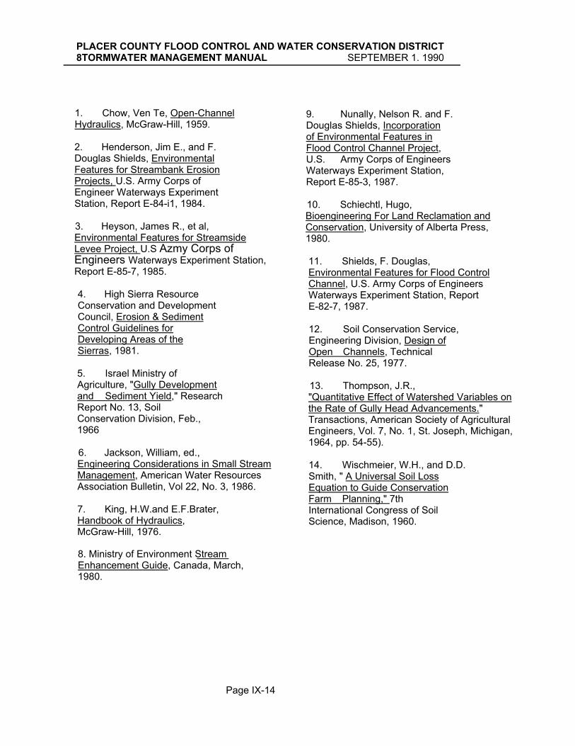
PLACER COUNTY FLOOD CONTROL AND WATER CONSERVATION DISTRICT 8TORMWATER MANAGEMENT MANUAL SEPTEMBER 1. 1990
1. Chow, Ven Te, Open-Channel Hydraulics, McGraw-Hill, 1959. 2. Henderson, Jim E., and F. Douglas Shields, Environmental Features for Streambank Erosion Projects, U.S. Army Corps of Engineer Waterways Experiment Station, Report E-84-i1, 1984. 3. Heyson, James R., et al, Environmental Features for Streamside Levee Project, U.S Azmy Corps of Engineers Waterways Experiment Station, Report E-85-7, 1985.
4. High Sierra Resource Conservation and Development Council, Erosion & Sediment Control Guidelines for Developing Areas of the Sierras, 1981.
5. Israel Ministry of Agriculture, "Gully Development and Sediment Yield," Research Report No. 13, Soil Conservation Division, Feb., 1966
6. Jackson, William, ed., Engineering Considerations in Small Stream Management, American Water Resources Association Bulletin, Vol 22, No. 3, 1986.
7. King, H.W.and E.F.Brater, Handbook of Hydraulics, McGraw-Hill, 1976.
9. Nunally, Nelson R. and F. Douglas Shields, Incorporation of Environmental Features in Flood Control Channel Project, U.S. Army Corps of Engineers Waterways Experiment Station, Report E-85-3, 1987.
10. Schiechtl, Hugo, Bioengineering For Land Reclamation and Conservation, University of Alberta Press, 1980. 11. Shields, F. Douglas, Environmental Features for Flood Control Channel, U.S. Army Corps of Engineers Waterways Experiment Station, Report E-82-7, 1987.
12. Soil Conservation Service, Engineering Division, Design of Open Channels, Technical Release No. 25, 1977.
13. Thompson, J.R., "Quantitative Effect of Watershed Variables on the Rate of Gully Head Advancements." Transactions, American Society of Agricultural Engineers, Vol. 7, No. 1, St. Joseph, Michigan, 1964, pp. 54-55).
14. Wischmeier, W.H., and D.D. Smith, " A Universal Soil Loss Equation to Guide Conservation Farm Planning," 7th International Congress of Soil Science, Madison, 1960.
8. Ministry of Environment Stream Enhancement Guide, Canada, March, 1980.
Page IX-14
PLACER COUNTY FLOOD CONTROL AND WATER CONSERVATION DISTRICTSTORMWATER MANAGEMENT MANUAL -- GLOSSARY SEPTEMBER 1, 1990
Conveyance -- A measure of the water carrying capacity of a stream or channel.
Critical Depth -- Depth at which specific energy is a minimum. Conditions the maximum flow will occur.
Critical Flow -- That flow in open channels at which the energy content of the fluid is at a minimum. Also, that flow which has a Froude number of one.
Acre-Foot -- The amount of water that will cover one acre to a depth of one foot. (Equals 43,560 cubic feet).
Backwater -- An unnaturally high stage in stream caused by obstruction or confinement of flow, as by a dam, a bridge, or a levee. Its measure is the excess of unnatural over natural stage, not the difference in stage upstream and downstream from its cause.
Bank -- The lateral boundary of a stream confining water flow. The bank on the left side of a channel looking downstream is called the left bank, etc. Critical Slope -- That slope at
which the maximum flow will occur at the minimum velocity. The slope or grade that is exactly equal to the loss of head per foot resulting from
carrying ability of a drainage
uniform flow at critical depth;
refer to storage capacity.
Channel -- Refers to a drainageway which has been created or extensively modified for the purpose of conveying floodwaters, and is therefore, no longer a watercourse in its natural condition. Concentrated Flow -- Flowing water that has been accumulated in to a single fairly narrow stream.
Confluence -- A junction of streams.
Control -- A section or reach of an open conduit or stream channel which maintains a stable relationship between stage and discharge.
Critical Velocity -- Mean velocity of flow when flow is at critical depth.
Culvert -- A closed conduit, other than a bridge, which allows water to pass under a road or highway.
Design Flood -- The peak discharge (when appropriate, the volume, stage, or wave crest elevation) of the flood associated with the probability of exceedance selected for design.
Capacity -- The effective
flow at a depth that will give
structure facility. May also
the slope of a conduit which will produce critical flow.

PLACER COUNTY FLOOD CONTROL AND WATER CONSERVATION DISTRICTBTORMWATER MANAGEMENT MANUAL -- GLOSSARY SEPTEMBER 1. 1990
Energy Dissipator -- A structure for the purpose of slowing the flow of water and reducing the erosive forces present in any rapidly flowing body of water.
Energy Grade Line -- The line which represents the total energy gradient along the channel. It is established by adding together the potential energy expressed as the water surface elevation referenced to a datum and the kinetic energy (usually expressed as velocity head) at points along the stream bed or channel floor.
Energy Head -- The elevation of the hydraulic grade line at any section plus the velocity head of the mean velocity of the water in that section.
Erosion -- The wearing away of a surface by some external force. In the case of drainage terminology, this term generally refers to the wearing away of the earth's surface by flowing water. It can also refer to the wear on a structural surface by flowing water and the material carried therein.
Erosion and Scour -- The cutting or wearing away by the forces of water of the banks and bed of a channel in horizontal and vertical directions, respectively.
Erosion and Accretion -- Loss and gain of land, respectively, by the gradual action of a
Design Storm -- That particular storm which contributes runoff which the drainage facilities were designed to handle. This storm is selected for design on the basis of its probability of exceedance or average recurrence interval.
Detention storage -- Surface water allowed to temporarily accumulate in ponds, basins, reservoirs or other types of holding facility and which is ultimately returned to a watercourse or other drainage system as runoff is in detention storage.
Discharge -- A volume of water flowing past a give point per unit of time. Generally specified in cubic feet per second.
Diversion -- The change in character, location, direction, or quantity of flow of a natural drainage course. A deflection of flood water is not diversion.
Drainage System -- Usually a system of underground conduits and collector structures which flow to a single point of discharge.
Drainageways -- Any path along which water flows when acted upon by gravity. Ephemeral Stream -- A stream or reach of stream that flows briefly only in direct response to precipitation.

PLACER COUNTY FLOOD CONTROL AND WATER CONSERVATION DISTRICTBTORMWATER MANAGEMENT MANUAL -- GLOSSARY SEPTEMBER 1. 1990
stream in shifting its channel by cutting one bank while it builds on the opposite bank. Property is lost by erosion and gained by accretion but not by avulsion when the shift from one channel to another is sudden. Property is gained by reliction when a lake recedes.
Flap Gate -- This is a form of valve that is designed so that a minimum force is required to push it open but when a greater water pressure is present on the outside of the valve, it remains shut so as to prevent water from flowing in the wrong direction. Construction is simple with a metal cover hanging from an overhead rod or pinion at the end of a culvert or drain.
Flood -- In common usage, an event where a stream overflows its normal banks. In frequency analysis it means an annual flood that may not overflow the banks.
Flood Frequency -- Also referred to as exceedance interval, recurrence interval or return period; the average time interval between actual occurrences of a hydrological event of a given or greater magnitude; the percent chance of occurrence is the reciprocal of .flood frequency, e.g., a 2 percent chance of occurrence is the reciprocal statement of a 50--year flood. (See Probability of Exceedance.)
Floodplain -- Normally dry land areas subject to periodic temporary inundation by stream flow or tidal overflow. Land formed by deposition of sediment by water: alluvial land.
Floodproof -- To design and construct individual buildings, facilities, and their sites to protect against structural failure, to keep water out or reduce the effects of water entry.
Flood Routing -- Determining the changes in a floodwave as it moves downstream through a valley or through a reservoir.
Flood Stage -- The elevation at which overflow of the natural banks of a stream begins to cause damage in the reach in which the elevation is measured.
Flood Waters -- Former stream water which have escaped from a watercourse (and its overflow channel) and flow or stand over adjoining lands. They remain as such until they disappear from the surface by infiltration, evaporation, or return to a natural watercourse. They do not become surface waters by mingling with such waters, nor stream waters .by eroding a temporary channel. Flood Wave -- The rise and fall in stream flow during and after a storm.

PLACER COUNTY FLOOD CONTROL AND WATER CONSERVATION DISTRICTSTORMWATER MANAGEMENT MANUAL -- GLOSSARY SEPTEMBER 1, 1990
Gradient (Slope) -- The rate of ascent or descent expressed as a percent or as a decimal as determined by the ratio of the change in elevation to the length.
Gradually Varied Flow -- A classification of flow where changes in depth and velocity take place slowly over large distances, resistance to flow dominates and acceleration forces are neglected.
Head -- Represents an available force equivalent to a certain depth of water. This is the motivating force in effecting the movement of water. The height of water above any point or plane or reference. Used also in various compound expressions, such as energy head, entrance head, friction head, static head, pressure head, lost head, etc.
Headcutting -- Progressive scouring and degrading of a streambed at a relatively rapid rate in the upstream direction, usually characterized by one or a series of vertical falls.
Hydraulic Gradient -- A line which represents the relative force available due to the potential energy available. This is a combination of energy due to the .height of the water and the internal pressure. In any open channel, this line corresponds to the water surface. In a closed conduit, if several openings were placed along the top of the pipe and
Floodway -- A zone of the floodplain, designated by FEMA under the National-Flood Insurance program, which must be preserved for allowing passage of the base flood discharge without increasing water elevations more than one foot. Velocities and depths in the floodway are more hazardous than in rest of the floodplain.
Flow -- A term used to define the movement of water, silt, sand, etc.; discharge; total quantity carried by a stream.
Flow Line -- A term used to describe the line connecting the low points in a watercourse.
Flow Regime -- The system or order characteristic of streamflow with respect to velocity, depth, and specific energy.
Freeboard -- (1) The vertical distance between the level of the water surface usually corresponding to the design flow and a point of interest such as a bridge beam, levee top or specific location on the roadway grade. (2) The distance between the normal operating level and the top of th sides of an open conduit the crest of a dam etc., designed -to allow for wave action, floating debris, or any other condition or emergency, without overtopping structure.

PLACER COUNTY FLOOD CONTROL AND WATER CONSERVATION DISTRICTSTORMWATER MANAGEMENT MANUAL -- GLOSSARY SEPTEMBER 1, 1990
open tubes inserted, a line connecting the water surface in each of these tubes would represent the hydraulic grade line.
Hydraulic Radius -- The cross sectional area of a stream of water divided by the length of that part of its periphery in contact with its containing conduit; the ratio of area to wetter perimeter.
Hydrograph -- A graph showing stage, flow, velocity, or other property of water with respect to time.
Hydrology -- The science dealing with the occurrence and movement of water upon and beneath the land areas of the earth. Overlaps and includes portions of other sciences such as meteorology and geology.
Hyetograph -- Graphical representation of rainfall intensity against time.
Incised Channel -- Those channels which have been cut relatively deep into underlying formations by natural processes. Characteristics include relatively straight alignment and high, steep banks such that overflow rarely occurs, if ever.
Infiltration -- The passage of water through the soil surface into the ground.
Inlet Time -- The time required for storm runoff to flow from the most remote point, in flow time, of a drainage area to the point where it enters a drain or culvert.
Intermittent Stream -- A watercourse that has significant flow 30 days after the last significant storm or has a well-defined channel.
Invert -- The bottom of a drainage facility along which the lowest flows would pass.
Inverted Siphon -- A pipe for conducting water beneath a depressed place. A true inverted siphon is a culvert which has the middle portion at a lower elevation than either the inlet or the outlet and in which a vacuum is created at some point in the pipe. A sag culvert is similar, but the vacuum is not essential to its operation.
Isohyetal Line -- A line drawn on a map or chart joining points that receive the same amount of precipitation.
Isohyetal Map -- A map containing isohyetal lines and showing rainfall intensities.
Lag -- Variously defined as time from beginning (or center of mass) of rainfall to peak (or center of mass) of runoff.
Laminar Flow -- That type of flow in which each particle moves in a direction parallel

PLACER COUNTY FLOOD CONTROL AND WATER CONSERVATION DISTRICTSTORMWATER MANAGEMENT MANUAL -- GLOSSARY SEPTEMBER 1. 1990
to every other particle and in which the head loss is approximately proportional to the velocity (as opposed to turbulent flow).
Lateral -- In a roadway drainage system, a drainage conduit transporting water from inlet points to the main drain truck line.
Levee -- An embankment to prevent inundation.
Mean Annual Flood -- The flood discharge with a recurrence interval of 2.33 years.
Meander -- In connection with streams, a winding channel usually in an erodible, alluvial valley. A reverse or S-shaped curve or series of curves formed by erosion of the concave bank, especially at the downstream end, characterized by curved flow and alternating shoals and bank erosions. Meandering is a stage in the migratory movement of the channel, as a whole, down the valley.
Meander Plug (Clay Plug) - - D e p osits of
cohesive m a terials in old channel bendways:These plugs are sufficiently resistant to erosion to serve as essentially semi-permanent geological-controls to advancing channel migrations.
Meander Scroll -- Evidence of historical meander patterns in the form of lines visible on the inside of meander bends
(particularly on aerial photographs) which resemble a spiral or convoluted form in ornamental design. These lines are concentric and regular forms in high sinuosity channels and are largely absent, in poorly developed braided channels.
Natural Stream -- refers to a natural watercourse that has not been significantly disturbed by development, and the native vegetation is therefore still present.
Normal Depth -- The depth at which flow is steady and hydraulic characteristics are uniform.
Normal Water Surface (Natural Water Surface) -- The surface associated with flow in natural streams.
Open Channel -- Any conveyance in which water flows with a free surface. Outfall -- Discharge or point of discharge of a culvert or other closed conduit.
Peak Flow -- Maximum momentary stage or discharge of a stream in flood. Design Discharge.
Permeability -- The property of soils which permits the passage of any fluid. Permeability depends on grain size, void ratio, shape and arrangement of pores.

PLACER COUNTY FLOOD CONTROL AND WATER CONSERVATION DISTRICTBTORMWATER MANAGEMENT MANUAL -- GLOSSARY SEPTEMBER 1. 1990
Retention storage -- Water which accumulates and ponds in natural or excavated depressions in the soil surface with no possibility for escape as runoff.
Riparian -- Pertaining to the banks and other adjacent, terrestrial environs of freshwater bodies, watercourses, and surface emergent aquifers, whose imported waters provide soil moisture significantly in excess of that available through local precipitation.
Risk -- The consequences associated with the probability of flooding attributable to an encroachment. It shall include the potential for property loss and hazard to life during the service life of the highway.
Runoff -- That part of the precipitation which appears in the surface streams.
Scour -- The result of erosive action of running water, primarily in streams, excavating and carrying away material from the bed and banks. Wearing away by abrasive action.
Sediment -- Fragmentary material that originates from weathering-of rocks and is transported by, suspended in, or deposited by water. Sheet Flow --.Any flow spread out and not confined: i.e., flow across a flat open field.
Point of Concentration -- That point at which the water flowing from a given drainage area concentrates.
Probability of Esceedance -The statistical probability, expressed as a percentage, of a hydrologic event occurring or being exceeded in any given year. The probability (p) of a storm or flood is the reciprocal of the average recurrence interval (N)
Probable Maximum Flood -- The flood discharge that may be expected from the most severe combination of critical meteorological and hydrological conditions that are.reasonable possible in the region.
Rapidly Varied Flow -- A classification of flow where changes in depth and velocity take place over short distances, acceleration forces dominate, and energy loss due to friction is minor.
Reach -- The length of a channel uniform with respect to discharge, depth, area, and slope. More generally, any length of a river or drainage course.
Regime -- The system of order characteristic of a stream: its behavior .with respect to velocity and volume, form of and changes in channel, capacity to transport sediment, amount of material supplied for transportation, etc.

PLACER COUNTY FLOOD CONTROL AND WATER CONSERVATION DISTRICTSTORMWATER MANAGEMENT MANUAL -- GLOSSARY SEPTEMBER l~ 1990
Storage Basin -- Space for detention or retention of water for future flow, naturally in channel and marginal soils, or artificially in reservoirs.
Storm -- A disturbance of the ordinary, average conditions of the atmosphere which, unless specifically qualified, may include any or all meteorological disturbances, such as wind, rain, snow, hail, or thunder.
Storm Drain (or Storm-Drain System) -- is a combination of underground conduits and surface-inlet structures constructed for the purpose of removing runoff from the ground surface, usually from the street pavement, and conveying it to some downstream discharge point.
Storm Water Management -- The recognition of adverse drainage resulting from altered runoff and the solutions resulting from the cooperative efforts of public agencies and the private sector to mitigate, abate, or reverse those adverse results.
Stream Power -- An expression used in predicting bed forms and hence bed load transport in alluvial channels. It is the product of the mean velocity, the specific .weight of the water-sediment mixture, the normal depth of flow and the slope.
Sinuosity -- The ratio of length of the river thalweg to the length of the valley proper.
Slope -- (1) Gradient of a stream. (2) Inclination of the face of and embankment, expressed as the ratio of horizontal to vertical projection: or (3) The face of an inclined embankment or cut slope. In hydraulics it is expressed as percent or in decimal form.
Slough -- (1)Pronounced SLU. A side or overflow channel in which water is continually present. It is stagnant or slack: also a waterway in a tidal marsh. (2) Pronounced SLUFF. Slide or slipout of a thin mantle of earth, especially in a series of small movements.
Stage -- The elevation of a water surface above its minimum: also above or below an established "low water" plane; hence above or below any datum of reference; gage height.
Steady Flow -- A flow in which the flow rate or quantity of fluid passing a given point per unit of time remains constant.
Storage -- Detention, or retention of water for future flow, naturally in channel and marginal soils or artificially in reservoirs.

PLACER COUNTY FLOOD CONTROL AND WATER CONSERVATION DISTRICTSTORMWATER MANAGEMENT MANUAL -- GLOSSARY SEPTEMBER 1. 1990
and torrential. Also, that flow which has a Froude number greater than one.
Surface Runoff -- The movement of water on earth's surface, whether flow is over surface of ground or in channels.
Surface Runoff -- Total precipitation minus interception, evaporation, and infiltration.
Surface Storage -- Natural or man-made roughness of a land surface, which stores some or all of the surface runoff of a storm.
Surface Waters -- Surface waters are those which have been precipitated on the land from the sky or forced to the surface in springs, and which have then spread over the surface of the ground without being collected into a definite body or channel. They appear as puddles, sheet or overland flow, and rills, and continue to be surface waters until they disappear from the surface by infiltration or evaporation, or until by overland or vagrant flow they reach well-defined watercourses or standing bodies of water like lakes or seas.
Suspended Load -- Sediment that is supported by the upward components of turbulent currents in a stream and that stay in suspension for appreciable amount of time.
Stream Response -- Changes in the dynamic equilibrium of a stream by any one, or combination of various causes.
Subcritical Flow -- In this state, gravity forces are dominant, so that the flow has a low velocity and is often described as tranquil and streaming. Also, that flow which has a Froude number less than one.
Street Conveyance -- is the process of utilizing an existing or newly designed street to convey storm runoff to some downstream discharge point. Such storm runoff is usually generated from adjacent lots and from the road surface itself. This runoff is controlled, particularly for newly designed street systems, in order to limit runoff quantity to a specified frequency flood event, thus minimizing interference with vehicular traffic and containing the runoff between the curbs and/or within the right-of-way/drainage easement.
Subdrain -- A conduit for collecting and disposing of underground water. It generally consists of a pipe, with perforations in the bottom through which water can enter.
Supercritical Flow -- In this state, inertia forces are dominant, so that flow has a high velocity and is usually described as rapid, shooting

PLACER COUNTY FLOOD CONTROL AND WATER CONSERVATION DISTRICTSTORMWATER MANAGEMENT MANUAL -- GLOSSARY SEPTEMBER 1. 1990
uniformly over the watershed, with the direct runoff generated at a uniform rate during the given storm duration.
Unsteady Flow -- A flow in which the velocity changes with respect to space and time.
Velocity Head -- A term used in hydraulics to represent the kinetic energy of flowing water. This "head" is represented by a column of standing water equivalent in potential energy to the kinetic energy of the moving water calculated as (V2/2g) where the "V" represents the velocity in feet per second and "g" represents the potential acceleration due to gravity, in feet per second per second.
Watercourse -- A definite channel with bed and banks within which water flows, either continuously or in season. A watercourse is continuous in the direction of flow and may extend laterally beyond the definite banks to include overflow channels contiguous to the ordinary channel. The term does not include artificial channels such as canals and drains, except natural channels, trained or restrained by the works of man. Neither does it include depressions or swales through which surface or errant water pass.
Swale -- A shallow, gentle depression in the earth's surface. This tends to collect the waters to some extent and is considered in a sense as a drainage course, although waters in a swale are not considered stream waters.
Thalweg -- The line following the lowest part of a valley, whether under water or not. Usually the line following the deepest part of the bed or channel of a river.
Time of concentration -- The time required for storm runoff to flow from the most remote point, in flow time, of a drainage area to the point under consideration.
Time to peak, Tp -- Time from beginning of rise to the peak of the hydrograph.
Trash Rack -- A grid or screen across a stream designed to catch floating debris.
Turbulent Flow -- That type of flow in which any particle may move in any direction with respect to any other particle, and in which the head loss is approximately proportional to the square of the velocity.
Undercut -- Erosion of the low part of a.steep bank so as to compromise stability of the upper part. Unit hydrograph -- A discharge hydrograph coming from one inch of direct runoff distributed

PLACER COUNTY FLOOD CONTROL AND WATER CONSERVATION DISTRICTSTORMWATER MANAGEMENT MANUAL -- GLOSSARY SEPTEMBER 1. 1990
Watershed -- The area contributing direct runoff to a stream. Usually it is assumed that base flow in the stream also comes from the same area.
Waterways -- That portion of a watercourse which is actually occupied by water.
Weir -- A low overflow dam or sill for measuring, diverting, or checking flow.
Wetland -- A zone periodically or continuously submerged or having high soil moisture, which has aquatic or riparian components or both, and is maintained by imported water supplies in excess of those available through local precipitation.
-11-

PLACER COUNTY FLOOD CONTROL AND WATER CONSERVATION DISTRICT
STORMWATER MANAGEMENT MANUAL ADDENDUM 1
The policies and standards in this addendum are now in effect and, where applicable, supersede the respective portions of the Stormwater Management Manual. The addendum will be incorporated in revisions to the manual at a later date.
Contents
1. Overland Flow Parameter Guidelines……………………………………………………..……1
2. Overland Flow Path……………………………………………………………………………… 2
3. Collector Flow Equation (Clarification) …………………………………………………...…....2
4. Default Response Times for Common Land Uses…………………………………………….2
5. Hydraulic Grade Line Options ……………………………………………………………….....2 6. Rectangular Manhole Loss Coefficients……….............................…………………………..3
8. Effects of Woody Debris.…………………………………………………………………..….….3
9. Effects of Future Channel Vegetation Growth ………………………………………….…..…3
10. Detention Requirement .…………………………………………………………………….…...3
11. Allowable Street Encroachments………………………………………………….………….…4
12. Small Watershed Method Examples Pre and Post Development (less than 200 acres).…5
Stormwater ManagementManual Addendum 1
July 1997
7. Roughness Coefficients for Culverts, Pipes and Channels…………………………………..3

PLACER COUNTY FLOOD CONTROL AND WATER CONSERVATION DISTRICT
1. Overland Flow Parameter Guidelines (Supplemental Guidelines, Chapter V)
The values indicated below will be accepted for conditions that are the same or similar to those described. These values are used generally in the District's watershed models. A single overland flow element may be used to reflect the predominant land use in the watershed. A second element may be used to represent a second major land use if
Stormwater ManagementManual Addendum 1
Page 1 October 1997
applicable.

PLACER COUNTY FLOOD CONTROL AND WATER CONSERVATION DISTRICT
2. Overland Flow Paths (Additional Requirement)
All drainage reports shall provide a map indicating the 100-year overland flow path and direction using arrows. These will simplify understanding of drainage patterns and help identify potential problem areas.
Overland release points shall be shown on grading plans to assure inspection.
3. Collector Flow Equation (Clarification)
Manning's equation, indicated on page V-10 and VI-5 may be substituted for Equation 5-4 (Page V-10; SWMM) to estimate response times (trc in gutter and pipe flow. The velocity computed for open channel flows using Manning's equation shall be increased by an adjustment factor to account for celerity (page V-13, SWMM).
4. Default Overland Response Times for Common Land Uses (Supplemental to Chapter V)
The following values will be accepted in lieu of a detailed evaluation using the equation or figures in the manual. In addition, these are the maximum values that will be accepted if a detailed evaluation is used.
Land Use Overland Response Time Single Family Residential > 4 units/acre
15 minutes to gutter
Multi-Family Residential 10 minutes to gutter Commercial to first inlet 10 minutes to first inlet
5. Hydraulic Grade Line Options (Supersedes Section VI D 2 d (3) (g), p VI-9)
Two options are provided to account for minor losses at junctions in underground drainage systems with the 10-year flood:
i) Minor losses may be ignored if the hydraulic grade line is a minimum of one foot
below all inlet grates and manhole covers of all structures of the upstream system except when required at the discretion of the agency or where:
a) inlet conduits) enter the junction at an angle greater than 45 degrees to the outlet conduit.
b) the velocity difference between the inlet conduits) and outlet conduit is greater than 5 feet/second.
Stormwater Management Page 2 October 1997 Manual Addendum 1

PLACER COUNTY FLOOD CONTROL AND WATER CONSERVATION DISTRICT
ii) Minor losses shall be calculated at each junction to design the hydraulic grade line at
least six (6) inches below all manhole covers, gratings, and inlets.
6. Rectangular Manhole Loss Coefficients (Supersedes Figure 6-1 p VI 8)
The scale for the head loss coefficients is corrected with this change.
7. Roughness Coefficient for Culverts, Pipes and Channels (Additional Requirement Pertaining to Section VI D 2 d (2), p VI 5 and Table 6-3)
A minimum "n" value of .015 shall be used in the Manning's formula for sizing conduits.
8. Effect of Woody Debris (Additional Requirement, Chapter VIII)
Experience indicates that open channels which drain watersheds with substantial tree coverage -especially natural, unmaintained watersheds - frequently generate and convey substantial quantities of floating woody debris. This debris is trapped against other fixed vegetation and manmade features, such as fences, effectively increasing the roughness of the conveyance. Where these conditions apply, nominal Manning n values for open channels determined using other criteria in the SMM shall be increased by at least 15%.
Stormwater Management Page 3 October 1997 Manual Addendum 1

PLACER COUNTY FLOOD CONTROL AND WATER CONSERVATION DISTRICT
9. Effect of Future Channel Vegetation Growth (Additional Requirement, Chapter VII)
Increases in watershed development can result in extensive growth of riparian vegetation in previously dry, bare channels, raising n-values to between .1-.2. Manning n values used in evaluating flow and depth in these channels shall take the potential for future growth of vegetation into account. The Manning n value used to determine floodplain boundaries may assume maintenance is provided if evidence of an acceptable maintenance program, including funding, is accepted. However, for determining elevations of adjacent structures, a Manning n value which assumes the channels to be unmaintained shall be used.
10. Detention Requirement (Supplemental Policy, Chapter VII)
Detention facilities shall be used to control the post-development 2-yr, 10-yr and 100-yr peak flow to pre-development objective outflows, as provided in VII D1. Exceptions are:
1. A specific District watershed plan supersedes this
requirement.
2. An acceptable alternative is agreed upon by the approving agency and the District. This would include instances where it would be infeasible to construct or operate the necessary facility. Acceptable alternatives include the contribution of funds, in additional to ordinary fees, for regional mitigation, such as regional detention facilities.
11. Allowable Street Encroachments (Supersedes Table 6-1)
The table on the following page supersedes Table 6-1.
Stormwater Management Page 4 October 1997 Manual Addendum 1

PLACER COUNTY FLOOD CONTROL AND WATER CONSERVATION DISTRICT
Stormwater ManagementManual Addendum 1
Page 5 October 1997
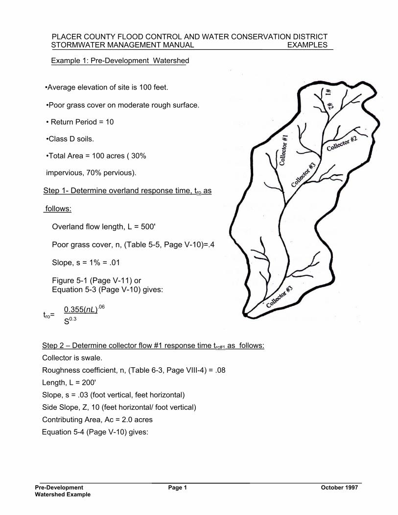
PLACER COUNTY FLOOD CONTROL AND WATER CONSERVATION DISTRICTSTORMWATER MANAGEMENT MANUAL EXAMPLES
Example 1: Pre-Development Watershed
•Average elevation of site is 100 feet.
•Poor grass cover on moderate rough surface.
• Return Period = 10
•Class D soils.
•Total Area = 100 acres ( 30%
impervious, 70% pervious).
Step 1- Determine overland response time, tro as
follows:
Overland flow length, L = 500' Poor grass cover, n, (Table 5-5, Page V-10)=.4 Slope, s = 1% = .01 Figure 5-1 (Page V-11) or Equation 5-3 (Page V-10) gives:
0.355(nL).06 tro= S0.3
Step 2 – Determine collector flow #1 response time trc#1 as follows: Collector is swale. Roughness coefficient, n, (Table 6-3, Page VIII-4) = .08 Length, L = 200' Slope, s = .03 (foot vertical, feet horizontal) Side Slope, Z, 10 (feet horizontal/ foot vertical) Contributing Area, Ac = 2.0 acres
Equation 5-4 (Page V-10) gives:
Pre-Development Page 1 October 1997 Watershed Example
_______________________________

PLACER COUNTY FLOOD CONTROL AND WATER CONSERVATION DISTRICT STORMWATER MANAGEMENT MANUAL EXAMPLES
Step 3 - Determine collector flow #2 response time. trc, repeat step #2 Collector is channel. Roughness coefficient, n, (Table 6-3, Page VI-6) = .06 Length, L = 800' Slope, s = .02 (foot vertical, feet horizontal) Side Slope, Z, 10 (feet horizontal/ foot vertical)
Contributing Area, Ac = 20.0 acres Equation 5-4 (Page V-10) gives: trc =2.6 minutes
Step 4 - Determine collector flow #3 response time
Collector is channel. Roughness coefficient, n, (Table 6-3, Page VIII-4) = .06 Length, L = 1700' Slope, s = .001 (foot vertical, feet horizontal) Side Slope, Z = 10 (feet horizontal/ foot vertical) Contributing Area, Ac = 100.0 acres Equation 5-4 (Page V-10) gives: trc = 11.4 minutes
Step 5 - Sum response times tr = tro + trc #1 + trc #2 = trc #3 = 49.2 minutes Step 6 - Determine unit peak discharge, q, from Figure 5-3A (Page V-14) Elevation = 100' Unit Peak Flow, q = .50 cfs/ac
Step 7 - Determine infiltration factor, Fi (cfs/acre) Elevation = 100’ Class D soils, residential landscaping with good cover, Infiltration rate, I (inch/hr) = 0.10 (Table 5-3) Equation 5-5 (Page V-13) gives: Fi = 0.17 (cfs/acre)
Pre-Development Page 2 October 1997 Watershed Example

PLACER COUNTY FLOOD CONTROL AND WATER CONSERVATION DISTRICTSTORMWATER MANAGEMENT MANUAL EXAMPLES
Step 8 – Compute total peak flow, Qp (cfs) using Equation 5 - 6
Pervious area = (1-.3)(100 acres) = 70 acres
acres Qp =100(.5) - (70)(.17) = 38.1 cfs
Pre Development Page 3 October 1997 Watershed Example

PLACER COUNTY FLOOD CONTROL AND WATER CONSERVATION DISTRICTSTORMWATER MANAGEMENT MANUAL EXAMPLES
Example 2 - Post-Development Watershed For this example, the following assumptions were made for post-development conditions:
See figure on right for a typical lot detail. Step 1 - Determine overland response time tro as follows:
• Lots are 100 feet deep and 60 feet wide. • Lots have constant slope of one percent. • Lots have Bermuda grass ground cover. • Average elevation of subdivision is 200 feet. • Class D soils. • Area = 65% impervious, 35% pervious. • Inlets are spaced at 300 feet. • The contributing area to each inlet is 1.4 acres.
Bermuda Grass Cover, (Table 5-5, Page V -10),n = .4
Overland flow length, L = 130'
Slope, s = 1% = .01 Figure 5-1 or Equation 5-3 gives:
0.355 (nL)0.6 s0.3 = 15.1 minutes
Step 2 - Determine collector flow response time, t rc
Collector flow to inlet is assumed to be gutter flow (assume v-gutter) Roughness coefficient, n = .015 Length, L = 300' Slope, s = .01 (foot vertical, feet horizontal) Assume v = 2.0 ft/s for this problem; Celerity Adjustment Factor c = Triangle = 1.33
trc __L_ = __ 300___ = 1.9 minutes c x 60 2 x 1.33 x 60
Step 3 - Sum response tr = tro + trc = 17.0 minutes
Post-Development Watershed Example
October 1997Page 1

PLACER COUNTY FLOOD CONTROL AND WATER CONSERVATION DISTRICT STORMWATER MANAGEMENT MANUAL EXAMPLES
Step 4 - Determine unit peak discharge from Figure 5-3A (Page V-14)
Elevation = 200'
Unit Peak Flow, q = 1.9 cfs/ac
Step 5 - Determine infiltration factor:
Elevation = 200'
Class D soils, residential landscaping with good cover,
Infiltration rate = .12 (Table 5-3, Page V-6 & 7, SWMM)
Equation 5-5 (Page V-13, SWMM) gives: Fi = .21
Step 5 - Compute total peak flow. Qp (cfs):
Pervious area = (.35)(1.4 acres) = .49 acres
Qp = 1.4(1.9) - (.49)(.21) = 2.55 cfs This establishes flow into the inlet. At locations in the drainage system downstream from the inlet, the response time is added, the area is increased, the unit flow is revised and conduits are sized appropriately.
Post-Development Watershed Example
October 1997Page 2

PLACER COUNTY FLOOD CONTROL AND WATER CONSERVATION DISTRICT STORMWATER MANAGEMENT MANUAL REQUIREMENTS FOR SUBMITTALS
c) Peak discharge computations for 100-year runoff REQUIREMENTS FOR SUBMITTALS
This section identifies the information to be submitted for review of plans for drainage and flood control features.
d) Assumptions as to upstream storage
6. A description of mitigations proposed or required.
7. A description of any special design features, such as storage basins, including the underlying design concepts
All of the information listed does not apply in every case, but review will proceed much faster if the necessary information is provided and is complete. Incomplete submittals will require subsequent submittals with additional information. 8. A map of the area to be served. The map
generally should be at a scale of 1 inch to 100 feet or 1 inch to 50 feet, having 2-foot contours, except where local governmental requirements modify this interval
It is suggested that questions regarding the omitted or need for particular information should be discussed with City, County or District staff in advance. 9. A layout of the area to be drained showing:
a) Streets and street names and street drainage flow direction
PRELIMINARY PLAN OF DEVELOPMENT
A preliminary plan of development is one prepared prior to receiving discretionary approvals. These include tentative maps, specific plans and environmental reports.
b) Irrigation ditches
c) Conflicting utilities (if necessary)
d) Drainage basin and sub-basins 1. A narrative report stating the goals, assumptions, and design concepts underlying the drainage system and including, at minimum, the information listed below. Additional information may be required as appropriate depending upon the size and complexity of the project.
e) Storm sewer layout with sizes and storm inlet locations
f) Cross-gutter locations and open drainage ways
g) Layout of major drainage system showing flows and directions 2. A vicinity map showing the location of the
project area in relationship to well-known features h) Scale and North Arrow
i) Signature blocks for review approvals 3. A topographic map of the watershed containing the area being studied and upstream watershed areas. (Maps at a 1 inch to 800 feet scale map are available from the County Department of Public Works)
j) Location map and subdivision names
10. Profiles of streets, utilities, and drainage components. The drainage profile shall also show inlet elevations and hydraulic grade lines
4. A table indexed to the watershed map which indicates drainage area, soil and cover types, land use, pervious infiltration rates, impervious areas and design flows for both pre-development and post-development conditions
11. Location and elevation of the outfall point of the storm drainage system for the planned project
12. Typical street cross sections
13. At the discretion of the approving agency, a plan, including funding, for operation and maintenance of facilities.
5. A description of the hydrologic methods used and identification of any extraordinary hydrologic conditions and how they were treated.
FLOODPLAIN ANALYSIS WITH HEC-2 OR HEC-RAS
a) Design criteria tabulation for 10-year and 100-year storm runoff
1. Plan view with: b) Peak discharge computations for pipe sizing
Version 7 R-1 Octobert 1997
____________________________

PLACER COUNTY FLOOD CONTROL AND WATER CONSERVATION DISTRICT STORMWATER MANAGEMENT MANUAL REQUIREMENTS FOR SUBMITTALS
a) Cross section locations with bank stations A field survey may be necessary to supplement design maps to locate utilities, test hole locations, and other items not accurately located on the maps. b) Maximum extent of inundation (floodplain)
2. Cross section plots with: Mapping for use in final design shall be of sufficient accuracy to enable horizontal locations to be set within 0.1 foot and elevations within 0.01 foot. Elevation datum shall be USGS unless other datum is specifically required. Horizontal control shall be tied to state grid coordinates and section corners to allow matching of maps for different projects.
a) Bank stations
b) Mannings n values
3. Profile view with:
a) Water surface
b) Energy grade line When alternate types of materials are considered, hydraulic design profiles must be shown for each material to verify that both are acceptable.
c) Invert elevations
d) Bridges with low chord and roadway elevations
Plans and Maps Formats 4. HEC-2 or HEC-RAS input on a diskette with an
explanatory narrative describing goals, methods and major assumptions.
1. Title block (lower right-hand corner preferred), Scale, Name of Professional Engineer or firm, Professional Engineer's Seal
IMPROVEMENT PLANS 2. Statement as to Specifications
Improvement plans are those submitted subsequent to discretionary approval of a project. Typically, improvement plans include construction drawings.
3. Approval spaces with date spaces, Date and Revisions, Drawing numbers
A narrative report shall be provided stating the goals, assumptions, and design concepts underlying the drainage system and include, at minimum, the information listed below. Additional information may be required as appropriate depending upon the size and complexity of the project.
Drainage Area Plan
1. North Arrow
2. Contours (maximum 2-foot intervals)
3. Location & elevation of USGS bench marks
4. Property lines, Boundary lines (counties, districts, tributary area) 5. Streets and street names & approximate grades with width
The following sections cover specific requirements of final construction drawings and specifications for drainage systems. A complete review of utilities, property locations, and other items which may affect construction of the system must also be provided, including, but not limited to:
5. Streets and street names and approximate grades with width
6. Subdivision (name and location by section) 1. Subdivision plats, section lines, and corners,
utility easements, highway right-of-ways, and any other property data.
7. Irrigation ditches
8. Proposed piping and open drainage ways
9. Existing drainage structures and ways including flow directions
2. As-built drawings of existing streets or highways wherever would affect design or construction.
10. Drainage sub-basin boundaries, Easements required
3. Records of existing utilities, pipelines, and structures both above and below ground. Data which are incomplete or questionable should be checked by field survey.
11. Proposed curbs and gutters and gutter flow directions
4. Size, construction, material, invert elevations, area served and type of development.
12. Proposed cross pan and flow directions, inlet location and inlet sizes
Version 7 R-2 Octobert 1997

PLACER COUNTY FLOOD CONTROL AND WATER CONSERVATION DISTRICT STORMWATER MANAGEMENT MANUAL REQUIREMENTS FOR SUBMITTALS 13. Critical minimum finished floor elevations for
protection from 100-year storm runoff e) watershed parameters (slope, area, etc.)
reflected in the inflow hydrographs
f) inflow hydrographs Construction Plans g) storm routings 1. North Arrow, Property lines and ownership or
subdivision information h) routings summary (in tabular form)
i) drawdown time 2. Street names and easements with width information j) expected sedimentation rate
3. Test hole locations and log k) soils and geotechnical report 4. Existing utility lines (buried), location and depth
water, gas, telephone, storm drainage, irrigation ditches sanitary sewers
3. Maps and Drawings
a) location map showing watershed boundaries.
b) basin drawings basin drawings should show plan and vertical views along with dimensions of all structures and features.
5. Vertical and horizontal grids with scales
6. Ground surface existing and proposed
7. Existing utility lines where crossed c) freeboard 8. Pipes, plan showing stationing profile, grades,
inlet and outlet details size, lengths between manholes and type
d) basin bottom slopes
e) low flow channel
f) trash racks 9. Manhole details (station number and invert elevations) g) fencing
10. Typical bedding detail h) maintenance access 11. Open channels plan showing stationing, profile,
and grades typical cross section, lining details i) landscaping
Soil and Geotechnical Report Requirements Special structures (manholes, head walls, trash racks, etc.) plan, elevation, details of design and appurtenances
A soil and geotechnical report may be required at the discretion of the approving agency and would include:
STORAGE BASINS 1. Site geology including bedding, foliation,
fracture, joint, fault and land slide plane attitudes. The following information regarding storage basin shall be submitted with a stormwater management plan. 2. Seismic conditions including fault locations and
potential seismic surface movements respective loadings and parameters of seismic shaking. 1. A narrative description of the design goals,
methods, criteria and assumptions. The description shall also address the choice of location and potential for joint use.
3. Potential impact of reservoir loading on geologic structure should be evaluated.
4. Detailed descriptions, locations, and logs of all field explorations.
2. Design Data, including:
a) objective outflow 5. Field and laboratory tests and analysis
descriptions and results. b) inflow hydrograph
c) storage-stage-data 6. Ground water table elevation and analysis of near surface groundwater movement. d) discharge-stage data
Version 7 R-3 Octobert 1997

PLACER COUNTY FLOOD CONTROL AND WATER CONSERVATION DISTRICT STORMWATER MANAGEMENT MANUAL REQUIREMENTS FOR SUBMITTALS 7. Recommended design parameters including, but
not limited to, the following for the dam and its natural abutments and slopes adjacent reservoir areas:
a) Lateral earth loadings
b) Shear strengths
c) Bearing capacities
d) Permeability
e) Slope stability analysis when saturated and during rapid drawdown conditions
f) Sieve analysis
g) Sand equivalents
h) Liquefaction analysis and if appropriate; mitigation
i) Seismic Seiche analysis
j) UBC Chapter 70
8. Special design and construction recommendations including, but not limited to the following:
a) Foundation preparation requirements
b) Suitability of materials for embankments (gradation, sand equivalent, etc.) and abutments
c) Compaction methods and minimum requirements
d) Seepage and piping control provisions
e) Potential for settlement
f) Necessity of impervious core or shear key
g) Erosion control of abutment
h) Seismic considerations - Minimum design factors of safety are:
Without Seismic
With Seismic
Embankment, 1.5 1.1 abutment and adjacent slope stability
Seepage, piping 1.5 --
Version 7 R-4 Octobert 1997

PLACER COUNTY FLOOD CONTROL AND WATER CONSERVATION DISTRICT STORMWATER MANAGEMENT MANUAL REQUIREMENTS FOR SUBMITTALS
Version 7 R-5 Octobert 1997
FLOODPLAIN ANALYSIS WITH HEC-2
OR HEC-RAS
1. Plan view with:
a) Cross section location with bank stations.
b) Maximum extent of inundation (flood plain)
2. Cross section plots with:
a) Bank stations
b) Manning’s n values
3. Profile view with:
a) Water surface
b) Energy grade line
c) Invert elevations
d) Bridges with low chord and roadway elevations
4. HEC-2 or HEC-RAS input on a diskette with an explanatory narrative describing goals, methods and major assumptions.