storm water pollution control plan
TRANSCRIPT

Storm Water Pollution Control Plan
West Side Quarry 6655 SW Hergert Road, in Cornelius
Washington County, Oregon
Operator: Columbia Northwest Recycling, Inc.
6655 SW Hergert Rd, Cornelius, OR 97113
Owner: West Side Quarry. LLC
Mailing Address: P.O. Box 1060, Woodburn, OR 97071
DEQ File No.109757/DOGAMI ID. 34-0026
Site Contact: Jeremy Philippi (503) 357-9326
Prepared by
March 17, 2021
This report was prepared under the supervision and direction of the undersigned. The undersigned have the specific qualifications based on education, training, and experience in storm water management.
Advanced Remediation Technologies, Inc
RENEWAL 12/31/2021
Lance A Downs, PE, GE Sr. Principal Geotechnical Engineer

WEST SIDE QUARRY STORM WATER POLLUTION CONTROL PLAN
i
Record of Amendments to the SWPCP Date Change
Date Effective
Section Modified
Modifications/Changes Revision Submitted
to DOGAMI1
(Yes/No) 10/2020 03/2021 New
Plan New owner and operator, Transfer of Permit Site no longer mining and is in Reclamation phase. Added additional erosion control BMP’s focused on the reclamation phase of accepting fill material to the site. Some of the permanent BMP’s include:
Wheel wash system Settling Ponds Check Dams in ditches Culverts for crossing haul roads
Non-permanent BMPs include: Silt fencing Benching Wattles and straw bale Mulching & seeding
Yes
DOGAMI submission of all SWPCP revisions is not required. SWPCP revisions must be submitted only if they are made for any of the following reasons: Change in site contact; In response to a corrective action or inspection; Changes to the site or control measures that may significantly change the nature of pollutants present in storm water or mine dewatering discharge; or significantly increase the pollutant(s) levels, discharge frequency, or discharge volume or flow rate; Changes to the monitoring locations or outfalls.
If submission of SWPCP revisions is required, submit the revised pages of the SWPCP or site map to DOGAMI within 30 days of making the revisions. Review of the revisions by DOGAMI prior to implementation is not required, except any revision of monitoring locations. If DOGAMI does not response to the revisions within 30 days of submittal, the revisions are accepted. DEQ or DOGAMI may require the registrant to revise the SWPCP be submitted at any time.

WEST SIDE QUARRY STORM WATER POLLUTION CONTROL PLAN
ii
Table of Contents Page
1 Introduction ............................................................................................................. 1 1.1 Background .................................................................................. 1
2 SWPCP Coordinator and Duties ............................................................................ 3 2.1 Contact Information/Responsible Parties ..................................... 3
3 Operator Certification ............................................................................................. 4 4 Facility Description ................................................................................................. 5
4.1 Facility Location ............................................................................ 5 4.2 Facility Information ....................................................................... 5 4.2.1 General Site Description ....................................................... 5 4.2.2 Industrial Activities ................................................................ 6 4.3 Storm water Drainage System ...................................................... 7
5 Identification of Potential Storm Water Contaminants ......................................... 12 5.1 Significant Material Inventory ...................................................... 12 5.2 Spill and Leak Record ................................................................ 12 5.3 Potential Area for Storm Water Contamination ........................... 13 5.4 Summary of Storm Water Sampling Data ................................... 13
6 Storm Water Management Controls .................................................................... 14 6.1 Compliance with Other Regulatory Programs ............................. 14 6.2 Storm Water Management Practices .......................................... 14 6.3 Storm Water Treatment .............................................................. 15
7 Compliance Monitoring Plan ................................................................................ 17 7.1 Benchmarks ................................................................................ 18 7.2 Sampling Frequency ................................................................... 18 7.3 Sampling Procedure ................................................................... 18 7.3.1 Grab Samples ..................................................................... 19 7.3.2 Permit Requirements ........................................................... 19
8 Inspection, Reporting, and Record Keeping ........................................................ 21 8.1 SWPCP Summary ...................................................................... 21 8.2 Employee Training ...................................................................... 21 8.3 Implementation Schedule ........................................................... 21 8.4 Record Retention Requirements ................................................ 22 8.5 Area of Inspection and Frequency .............................................. 23 8.6 Provisions for Amendment of the Plan ....................................... 23
9 Spill Response and Prevention ............................................................................ 25 9.1 Spill Prevention ........................................................................... 25 9.2 Spill Response ............................................................................ 25

WEST SIDE QUARRY STORM WATER POLLUTION CONTROL PLAN
iii
9.3 Notification .................................................................................. 26 10 Baseline BMPs ..................................................................................................... 27
10.1 Erosion and Sediment Control .................................................... 27 10.1.1 Stabilize Exposed Areas and Contain Runoff ..................... 27 10.1.2 BMPs for Sediment Barriers ............................................... 28 10.1.3 BMPs for Check Dams, Sediment Filters ............................ 30 10.1.4 BMPs for other Perimeter Control Measures ...................... 33 10.2 Prevent Offsite Sediment Track-out ............................................ 36 10.2.1 Wet Weather Protocol ......................................................... 37 10.2.2 Sediment Removal ............................................................. 37 10.2.3 Cold weather considerations............................................... 37 10.3 Minimization of Exposure............................................................ 37 10.4 Oil and Grease ........................................................................... 38 10.4.1 BMPs for Equipment Storage ............................................. 38 10.5 Waste Chemicals and Material Disposal .................................... 39 10.6 Debris Control ............................................................................. 39 10.7 Housekeeping ............................................................................. 39 10.8 Spill Prevention and Response ................................................... 40 10.8.1 BMPs for Outdoor Storage Facilities ................................... 41 10.8.2 Storage Procedures ............................................................ 41 10.8.3 Secondary Containment ..................................................... 43 10.8.4 Drainage of Rainwater ........................................................ 43 10.9 Preventative Maintenance .......................................................... 43 10.9.1 Operation & Maintenance of wheel washers/wash racks .... 44

WEST SIDE QUARRY STORM WATER POLLUTION CONTROL PLAN
iv
List of Tables
Table 1: Characteristics of Storm Water Drainage Table 2: Significant Materials and Potential Pollutants Table 3: Inspection Schedule Table 4: Statewide Benchmarks Table 5: Implementation Schedule
List of Figures Following Page
Figure 1 and 1A: Site Location end of text Figure 2: Storm Water Site Drainage Plan end of text Figure 3A: STAGE 1 Reclamation end of text Figure 3B: STAGE 2 Reclamation end of text Figure 3C: STAGE 3 Reclamation end of text Figure 3D: Entrance & Truck Scale end of text
Appendices
Appendix A: Training Log Appendix B: Daily, Weekly and Annual Inspection Log Appendix C: Tier I Corrective Action Inspection Log Appendix D: 1200-A Permit Appendix E: Wheel Wash Operation and Maintenance Plan Appendix F: Spill Report Form

WEST SIDE QUARRY STORM WATER POLLUTION CONTROL PLAN
1
1 Introduction
1.1 Background
In 1972, Congress passed the Federal Water Pollution Control Act, also known as the Clean Water Act (CWA), to restore and maintain the quality of the nation’s waterways. The CWA recognized the need to control pollution that couldn’t be traced to a pipe – nonpoint pollution in storm water that drains into water bodies from diffuse locations dispersed over the existing terrain and surfaces.
The United States Environmental Protection Agency (USEPA) published the final reissuance of the National Pollution Discharge Elimination System (NPDES) Storm water Multi-Sector General Permit for Industrial Activities, which included provisions for the development of a Storm water Pollution Control Plan (SWPCP) by each industrial facility discharging storm water. The USEPA defines storm water as “storm water runoff, snowmelt runoff, and surface runoff and discharges” (Code of Federal Regulation [CFR] Title 40, Part 122, Section 26 (b)(14) (i-xi)).
Industries that perform certain industrial activities on-site (e.g., aggregate mining, processing of rock and sand, equipment maintenance and/or cleaning) are required to obtain coverage under the NPDES General Permit for Storm water Discharges Associated with Industrial Activity (Permit) to discharge storm water off-site. A permit is required because the facility may discharge storm water potentially impacted by industrial activities to public waters. To protect public waters from runoff potentially impacted by pollutants, the Permit requires that a SWPCP be developed for each facility covered by the permit.
The SWPCP outlines industrial activities (SIC 1429- primary, 1442 secondary) that could potentially contribute to storm water pollution and the management practices to be used by Operator’s employees to reduce this potential. The potential pollutants include sediment, turbidity, total metals and/or petroleum hydrocarbons. The proposed industrial activities performed at the facility which have the potential to impact storm water discharges include the following:
Material (crushed concrete, aggregate, boulders) storage, haul roads, and material processing – aggregate, loading haul trucks, temporary stock piling, dumping of reclamation fill are industrial activities that are an important part of the site activities and, therefore, are considered here. BMPs are described in Section 10 below.

WEST SIDE QUARRY STORM WATER POLLUTION CONTROL PLAN
2
This SWPCP is to be used as an active reference guide for site personnel, and is to be reviewed and modified, as necessary, at least annually. The plan specifies requirements to be followed by all personnel at the facility. The SWPCP has been developed to reduce or eliminate storm water pollution from the above listed industrial activities and was prepared in accordance with the requirements outlined in the Permit and the Storm water Management For Industrial Activities, Developing Pollution Prevention Plans and Best Management Practices Summary Guidance (Doc. No. EPA 832-R-92-006).
Development, implementation, and maintenance of the SWPCP will provide West Side Quarry with tools to reduce pollutants contained in storm water discharges and comply with the requirements of the NPDES Storm water General Permit 1200-A issued by Oregon Department of Environmental Quality DEQ) through approval by the US. Environmental Protection Agency (EPA). The Department of Geology and Mineral Industries (DOGAMI) through a memorandum of agreement acts as an agent for DEQ for the West Side Quarry (File No.109757; A copy of the 1200-A is attached as Appendix D). The primary goals of the SWPCP will be to:
Identify potential sources of pollutants that affect storm water discharges from the site;
Describe the best management practices (BMPs) that will be implemented to prevent or control the release of pollutants in storm water discharges; and
Create an implementation schedule to ensure that the practices described in this SWPCP are in fact implemented and to evaluate the plan’s effectiveness in reducing the pollutant levels in storm water discharges (if necessary).

WEST SIDE QUARRY STORM WATER POLLUTION CONTROL PLAN
3
2 SWPCP Coordinator and Duties
The SWPCP coordinator for the facility is Mr. Jeremy Philippi, Facility Manager (phone number (503) 357-9326 work. Mr. Philippi responsibilities and duties include the following:
Create a SWPCP team to aid in the implementation of the SWPCP Oversee maintenance practices identified as BMP’s in the SWPCP Implement and oversee employee training Conduct and/or provide for inspection and/or monitoring activities Identify other potential pollutant sources and make sure they are amended to the
SWPCP Ensure that any changes to the facility operation are addressed as amendments
to the SWPCP.
To aid in the implementation of the SWPCP, Mr. Jeremy Philippi (Facility Manager) will ensure that all housekeeping and monitoring procedures are implemented and documented.
2.1 Contact Information/Responsible Parties
Facility Owner:
West Side Quarry LLC Mailing Address: P.O. Box 1060 Woodburn, Oregon 97071 Telephone: (971) 216-0050 Contact: Mr. Brent Kerr, President [email protected]
Facility Operator:
Columbia Northwest Recycling, Inc. Physical Address: 6655 SW Hergert Road Cornelius, Oregon 97113 Telephone: (503) 357-9326 Contact: Mr. Jeremy Philippi, Facility Manager

WEST SIDE QUARRY STORM WATER POLLUTION CONTROL PLAN
4
3 Operator Certification
I certify under penalty of law that this SWPCP and all attachments were prepared under my direction or supervision in accordance with a system designed to assure that qualified personnel properly gather and evaluate information to determine compliance with the Industrial Storm water General Permit. Based on my inquiry of the person or persons who are responsible for storm water management at my facility, this SWPCP is, to the best of my knowledge and belief, true, accurate, and complete, and in full compliance with Permit Conditions, including the correct Best Management Practices from the applicable Storm water Management Manual. I am aware that there are significant penalties for submitting false information, including the possibility of fine and imprisonment for knowing violations.”
_Brent Kerr_________________________
Name (printed)*
_________________________________
Signature
_President_________________________
Title
_________________________________
Date
* Federal regulations require this document to be signed as follows:
For a corporation, by a principal executive officer of at least the level of vice president;
For a partnership or sole proprietorship, by a general partner or the proprietor, respectively; or for a municipality, state, federal, or other public facility, by either a principal executive officer or ranking elected official.

WEST SIDE QUARRY STORM WATER POLLUTION CONTROL PLAN
5
4 Facility Description
4.1 Facility Location
The West Side Quarry is located in Washington County just South-Southwest of the Cornelius, Oregon (see Figure 1). The facility is located in Washington County, in Section 20 of Township 1 South Range 3 West, Willamette Meridian. The facility address is 6655 SW Hergert Road, Cornelius, Oregon 97113 and is on tax lots 200 (80.32 acres [ac]) 405 (11.42 ac), and 700 (42.12 ac). The elevation of the site ranges between 290 and 690 feet. The site is surrounded by undeveloped forest terrain, agricultural and rural residential land uses.
4.2 Facility Information
4.2.1 General Site Description
The subject quarry site is located at the northern end of the Chehalem Mountains, which form the southwestern border of the Tualatin Valley lowland. The Chehalem Mountains are mapped by Trimble (1968) as Miocene and Pliocene Columbia River Basalts (CRB) comprising a series of tholeiitic flood basalts. Deformation of the CRB forms a structural basin below the Tualatin Valley which has been filled with up to 1,300 feet of lacustrine and fluvial deposits of lower Pliocene age (Trimble, 1963).
Two units of the Yakima subgroup of the CRB are exposed in the Chehalem Mountains including the Grande Ronde Basalt and the overlying Frenchman Springs Member of the Wanapum Basalt. Several flows make up the approximately 420-foot thick basalt sequence. The West Side Rock quarry generally bisects the Grande Ronde member of the CRB; Frenchman Springs basalt outcrops above the quarry at elevations above 900 feet.
The upper exposed layers of basalt form the deeply weathered and moderately eroded slopes of the Chehalem Mountains. Weathered zones measure up to 100 feet thick locally are described as red to brown clay (laterite) with fragments of decomposed basalt. Unweathered basalt is generally brownish-gray to dark blue-gray and fine grained.
WEST SIDE QUARRY STORM WATER POLLUTION CONTROL PLAN
6
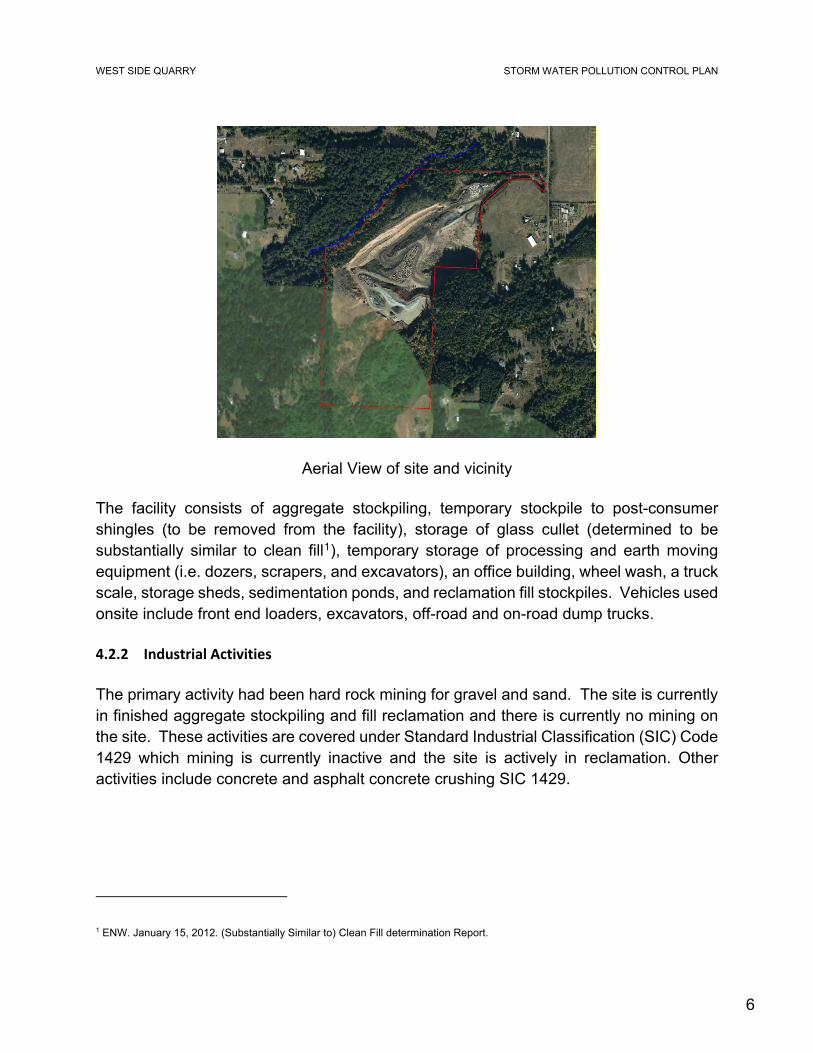
Aerial View of site and vicinity
The facility consists of aggregate stockpiling, temporary stockpile to post-consumer shingles (to be removed from the facility), storage of glass cullet (determined to be substantially similar to clean fill1), temporary storage of processing and earth moving equipment (i.e. dozers, scrapers, and excavators), an office building, wheel wash, a truck scale, storage sheds, sedimentation ponds, and reclamation fill stockpiles. Vehicles used onsite include front end loaders, excavators, off-road and on-road dump trucks.
4.2.2 Industrial Activities
The primary activity had been hard rock mining for gravel and sand. The site is currently in finished aggregate stockpiling and fill reclamation and there is currently no mining on the site. These activities are covered under Standard Industrial Classification (SIC) Code 1429 which mining is currently inactive and the site is actively in reclamation. Other activities include concrete and asphalt concrete crushing SIC 1429.
1 ENW. January 15, 2012. (Substantially Similar to) Clean Fill determination Report.

WEST SIDE QUARRY STORM WATER POLLUTION CONTROL PLAN
7
Name of Facility: West Side Quarry
Physical Address: 6655 SW Hergert Road Cornelius, Oregon 97113 Washington County
Latitude/Longitude:
Latitude: 45 28’ 9.49”N (degrees, minutes, seconds)
Longitude: -123 4’ 43.22” W
Estimated total area of the site exposed to storm water is: approximately 47.5 acres.
Estimated area of industrial activity at the site exposed to storm water related to aggregate and fill materials storage and haul road operation: approximately 32.1 acres.
Estimated area of industrial activity at the site exposed to storm water related to truck scale, wheel wash, paved entrance/exit road, and misc. storage approximately 1 acre in total.
Remaining area is vegetated and/or undisturbed.
4.3 Storm water Drainage System
The West Side Quarry site consist of two (2) drainage areas (DA). Table 1 describes the significant characteristics of the drainage area. Figure 2 shows the location of the drainage area and the apparent storm water drainage patterns on the site as of 2020.
The DA-1 site contains approximately 1.40 acres of dry and wet ponds and over 3,000 linear feet of vegetated ditches/swales with check dams which receive runoff from haul roads, material storage areas, and open areas of the site (see Figure 2). The vegetated ditches/swales with check dam will be modified (e.g., relocated to control run-off) as reclamation material is brought to the site. The vegetated settling ponds are connected by drainage ditches/swales that run dry during the end of summer/early fall months. The ponds will also be modified (e.g. relocated to control run-off) as reclamation material is brought to the site. The storm water drainage discharges at a single discharge point (Outfall 001) on the northeast side of the site. The drainage enters the Tualatin River

WEST SIDE QUARRY STORM WATER POLLUTION CONTROL PLAN
8
flood plain and follows small drainages before entering the headwater of the Tualatin River.
Storm water consisting of sheet flow from drainage area DA-1 is collected by small ditches connected to drainage swales connected to the dry and wet ponds (approximately 5 ponds) and discharges to an outfall (Outfall 001).
Pond #1 with vegetated side slope and armored with rip rap at inlet and outlet

WEST SIDE QUARRY STORM WATER POLLUTION CONTROL PLAN
9
Dry Pond #3 with vegetated side slopes and bottom
Pond #5 at southern extent of gravel pit (head of existing drainage channel)

WEST SIDE QUARRY STORM WATER POLLUTION CONTROL PLAN
10
Storm water consisting of sheet flow from primarily gravel and paved surfaces at the entrance of the site drainage area DA-2 is collected by small ditches connected to drainage swales and discharges to an outfall (Outfall 002) at the gate entrance.
Vegetated swale with armored check dams and bottom along paved entrance

WEST SIDE QUARRY STORM WATER POLLUTION CONTROL PLAN
11
Table 1: Characteristics of Storm Water Drainage
Drainage Area (1)
Flow Description Total Size(2) (sq-ft)
Impervious Area(2)
(sq-ft)
Drainage Discharge Point
DA-1
sheet flow primarily over gravel haul roads and stockpile and reclamation areas
1,400,185 462,060
Area sheet flow to drainage ditch that enters established drainage of the Tualatin River flood plain at Outfall 001.
DA-2
sheet flow primarily over paved roads, truck scales, and misc. storage areas
43,560 43,560
Area sheet flow to drainage ditch/swale that enters drainage along SW Hergert road at Outfall 002
(1) See Figure 2 (2) Areas are approximate based on Figure 2

WEST SIDE QUARRY STORM WATER POLLUTION CONTROL PLAN
12
5 Identification of Potential Storm Water Contaminants
5.1 Significant Material Inventory
Formerly the site was aggregate mining. Currently the site is in reclamation and receiving fill with an earth moving equipment on site. Equipment fueling is conducted by a mobile refueller (with a 750 gallon capacity2) to dispense fuel to equipment in the area of mining operations and aggregate stockpiling.
Table 2: Significant Materials and Potential Pollutants
Currently, asphalt shingles stored at the quarry will be transferred to another quarry with an asphalt batch plant. This material does not represent an impact to storm water. Glass cullet stored at the site has been tested and confirmed to be substantially similar to clean fill1 as determined by DEQ. This material will be utilized as reclamation fill at the site.
Area Potential Storm Water Pollutant Sources Potential Pollutants Former Quarry (current being reclaimed)
• Site preparation: road construction, placement of fill • Stockpiling and loading
Dust, TSS, TDS, turbidity, pH
Equipment Parking Area
• Fueling activities • Operation • Storage
Diesel fuel, oil and grease, heavy metals
Haul Roads • Equipment and truck traffic • Gravel road grading and resurfacing with aggregate
and/or glass cullet
Dust, TSS, turbidity, pH, diesel/gas fuel, oil and grease, heavy metals
5.2 Spill and Leak Record
The facility is required to retain records of any reportable spills in uncovered areas of the facility within the past three years. Responses or corrective action to reportable spills and deposition of spill material must be retained as well.
2 Note that the current volume of bulk storage petroleum product does not trip the equipment for a Spill Pollution Control Countermeasures plan.

WEST SIDE QUARRY STORM WATER POLLUTION CONTROL PLAN
13
5.3 Potential Area for Storm Water Contamination
The following potential source areas of storm water contamination were identified:
Vehicle\Equipment Parking; Employee parked vehicles\equipment and earth moving equipment staged throughout the site. Leaking fluids from parked vehicles and equipment can potentially contaminate storm water from this area. These contaminants may include diesel, hydraulic oil, motor oil, benzene, ethyl benzene, toluene, xylenes, MTBE, ethylene glycol, propylene glycol, copper, lead, and zinc.
Aggregate and reclamation fill temporary storage and handling: Aggregate and reclamation fill material will be transported to various designated areas on site for temporary storage prior to grading for fill and/or final placement. Aggregate and reclamation fill material will be stored in sorted piles. The potential contaminants may include suspended sediments/turbidity, petroleum hydrocarbons, metals, and effects on the pH of storm-derived water (see Table 2).
5.4 Summary of Storm Water Sampling Data
The facility maintains sampling data for at least three years and is stored on-site.

WEST SIDE QUARRY STORM WATER POLLUTION CONTROL PLAN
14
6 Storm Water Management Controls
6.1 Compliance with Other Regulatory Programs
EPA issued Oil Pollution Prevention Regulation that is codified in 40 CFR 112, to address oil spill prevention and response. Specific regulation in 40 CFR 112.7 I(1), as amended by the Oil Pollution Act of 1990, requires the preparation and submission of site-specific response plans for onshore facilities that could reasonably be expected to cause substantial harm to the environment by discharging oil and hazardous substances into or upon navigable waters, adjoining shorelines, and/or sensitive environments.
Spill Prevention, Control and Countermeasure (SPCC) Plans for facilities are prepared and implemented as required by EPA regulations contained in Title 40, Code of Federal Regulations, Part 112 (40 CFR 112). A non-transportation related facility is subject to SPCC regulations if: (a) the cumulative storage capacity of aboveground oil storage exceeds 1,320 gallons or underground oil storage exceeds 42,000 gallons or (b) the facility has had two discharges (each over 42 gallons) in any 12-month period or (c) the facility has discharged more than 1,000 gallons in a single discharge; and if, due to its location, the facility could reasonably be expected to discharge oil into or upon the navigable waters of the United States. The facility is not required to maintain a Spill Prevention Control and Countermeasure plan (SPCCP). Equipment is fueled by a 750-gallon mobile refueller, which does not exceed 1,320 gallons of above-ground storage, and is not always stored at the site.
The facility has an operating permit issued by DOGAMI for aggregate mining (mining and rock crushing activities are inactive) and the site is in the reclamation phase.
The facility utilizes a mobile concrete crusher that has an air quality operating permit (Source# 37-0539) issued by DEQ for crushing of recycling concrete.
6.2 Storm Water Management Practices
Upon reviewing the potential pollutants at the facility and the facility operations, a summary of existing Best Management Practices (BMPs) and proposed BMPs has been prepared. Existing BMPs implemented at the site include:
Spill prevention and response;

WEST SIDE QUARRY STORM WATER POLLUTION CONTROL PLAN
15
BMPs for outdoors materials storage and handling are included at the end of this document.
BMPs for Sediment Barriers included at the end of this document.
BMPs for Check Dams, Sediment Filters included at the end of this document.
BMPs for Wheel washer/wash rack included at the end of this document.
Potential significant stormwater exposure at the site is from sheet flow mainly across haul roads, equipment storage areas, and stockpile storage areas. Drainage from this area flow directly into drainage ditches along the haul roads away from surrounding the processing areas and stockpiles. The ditches and vegetated swales through check dams eventually enter the dry and wet ponds and into a single discharge point that makes up the storm water system. Stormwater flow discharges eventually enter the Tualatin River drainage basin. Section 10 of this plan details implementation and generalized detailed description of the BMPs that may be used for the site as reclamation proceeds as well as those referenced above.
6.3 Storm Water Treatment
Sheet flows off the haul roads, temporary equipment storage areas and temporary stockpiles areas are to be monitored and sorbents are to be used if visible sheen is observed prior to discharge to the drainage ditches (BMPs to reduce oil and grease associated with equipment and vehicle leaks, and/or spills). Additionally, filter berms and vegetated filter berms constructed along the impact areas should control and direct sheet flow to drainages with check dams and eventually to wet ponds for settling (BMPs to reduce settable solids, turbidity, and sedimentation). Ponds should be routinely maintained by removing sediments during dry months and utilizing recovered materials as reclamation fill. Stockpiles that are known to be stored through a wet season should be treated with sprayed on seed mulch to help reduce sediment erosion from the exposed stockpiles before discharges to surface water bodies (BMPs to reduce exposed soil erosion leading to, turbidity, and sedimentation). If the stockpiles can’t be treated then bench and/or stepping of the stockpiles should be implemented along with other control measures on the slopes and toe of the slope (proposed BMPs). Diversion (e.g. silt fencing at the toe of slopes and wattles on slopes of reclamation fill slopes) may be applied to the stockpiles to direct sediment laden flows to ditches, berms, and settling ponds before leaving the site.

WEST SIDE QUARRY STORM WATER POLLUTION CONTROL PLAN
16
Newly seeded fill area (October, 2020)

WEST SIDE QUARRY STORM WATER POLLUTION CONTROL PLAN
17
7 Compliance Monitoring Plan
Table 3, below, describes the required inspection schedule at the site. Visual inspections will be conducted by personnel that have completed employee training (Section 8.2) and are familiar with all aspects of the SWPCP. Site inspection forms are provided in Appendix B.
Carefully complete ALL sections of the form. They have been designed to document compliance with the requirements of Permit item B.7, Inspections. Inspection forms will be retained onsite and submitted to DOGAMI, ODEQ or agent upon request.
Table 3: Inspection Schedule
Frequency Items Daily, when operating, unless site is inaccessible due
to adverse weather conditions • Dikes • Check dams • Pond freeboard
Daily, when storm water runoff is occurring (including runoff from snow melt), unless site is
inaccessible due to adverse weather conditions
Monthly, if the entire site is temporarily stabilized or runoff is unlikely due to winter conditions (site is covered with snow, ice, or the ground is frozen) or seasonal arid periods.
• Mining clearing • Grading • Excavation areas
Weekly, when operating, unless site is
inaccessible due to adverse weather conditions All streams within 300 feet of an active pond
Monthly Areas of the site where industrial activities are exposed to storm water, including:
• Locations of BMPs • Material storage and stockpiling areas • Vehicle entrance/exit areas
Monthly, when discharging Monitoring point(s) for:
• Floating solids (associated with mining) • Foam • Visible oil sheen • Discoloration of discharge
Annually, before wet weather season (by Oct. 1st)
Storm water control facilities and drainage systems

WEST SIDE QUARRY STORM WATER POLLUTION CONTROL PLAN
18
7.1 Benchmarks
Benchmarks and reference concentrations for impairment pollutants are guideline concentrations, not limitations. These are reference to assist the permit registrant in determining whether site controls and BMP’s are effectively reducing pollutant concentrations in storm water discharged from the site.
Table 4: Statewide Benchmarks
Parameter Benchmark Frequency
pH 5.5 – 9.0 SU Four (4) times per year
Total Suspended Solids (TSS) 100 mg/L Four (4) times per year
Settleable Solids 0.20 ml/L Four (4) times per year
Total Oil & Grease 10 mg/L Four (4) times per year Note: mg/L – milligram per liter
Note: Two (2) sample collected before December 31, and Two (2) sample collected after January 1 each year
The 1200-A permit will identify which benchmarks pollutants must be monitored specific to the industrial activity and any secondary industrial activities including frequency and/or TMDLs that may be include in the permit..
7.2 Sampling Frequency
Typically the monitoring year is from July 1st to June 30th, which represents a water cycle. Storm water samples are to be collected four times per year at least 14 days apart. At least two samples should be collected before December 31st and two samples after January 1st. Sampling is typically required only during regular business/working hours on week days.
7.3 Sampling Procedure
To comply with storm water application requirements, the sample type (grab or composite) must be collected in accordance with 40 CFR 122.21(g)(7) and 40 CFR Part 136. The

WEST SIDE QUARRY STORM WATER POLLUTION CONTROL PLAN
19
storm water permit requirements clearly specify which pollutants must be analyzed. Although the requirements in 40 CFR 122.21(g)(7) do not explicitly specify either manual or automatic sampling techniques, the approved analytical methods contained in 40 CFR Part 136 direct that grab samples must be collected manually for certain pollutants.
7.3.1 Grab Samples
A grab sample is a discrete, individual sample taken within a short period of time (usually less than 15 minutes). Analysis of grab samples characterizes the quality of a storm water discharge at a given time of the discharge.
7.3.2 Permit Requirements
Grab samples should be collected for the following conditions:
For storm water discharges associated with industrial activity, a grab sample must be obtained during the first 12 hours of a storm event that produces a discharge. These samples are intended to characterize the maximum concentration of a pollutant that may occur in the discharge and/or may indicate intermingling of non-storm water discharges. Ideally the sample should be collected from the end of pipe discharge, or from a sampling manhole prior to discharge. Sampling should be conducted from aboveground, sampling personnel should NOT enter a sampling manhole to collect samples (if present).
Sampling for pH require either measuring the pH directly in the flow, or analyzing the sample within 15 minutes of the sample collection. pH may be measured in the field by obtaining accurate pH readings with a properly calibrated pH meter. pH meter for testing pH measurement must follow manufacturers’ specifications and keep meter in good working order.
Sampling Location:
Samples should be collected from the pipe discharge for Outfall 001 (Lat: N45° 28’ 19.31”, Long: W123° 4’ 38.33”) at the wet pond which is representative of the site and encompasses the largest drainage area (DA-1). The discharge pipe is a high-water outflow located approximately 6 feet blow top of bank of Pond #1. Care should be taken to allow easy access to the point of discharge by providing a clear path (e.g., brush

WEST SIDE QUARRY STORM WATER POLLUTION CONTROL PLAN
20
clearing). Sampling should only occur when there is a discharge from this pipe during or within 12-hours of a rain event.
Samples should be collected from the end of pipe discharge for Outfall 002 (Lat: N45° 28’ 18.10”, Long: W123° 4’ 25.55”) which is representative of the site entrance and encompasses potential wheeled-traffic sediment from the site and is representative of a paved drainage area (DA-2). The location of the discharge pipe is next to the access gate within the swale along the entrance road (see Figure 2).

WEST SIDE QUARRY STORM WATER POLLUTION CONTROL PLAN
21
8 Inspection, Reporting, and Record Keeping
8.1 SWPCP Summary
As per the requirements of West Side Quarry NPDES Storm Water 1200-A Permit issued by DEQ and administered by DOGAMI (File No. 109757/ ID. 34-0026), West Side Quarry is required to prepare a SWPCP. The SWPCP will be kept at each facility and will be made available to state and federal compliance officers upon request.
8.2 Employee Training
An employee training program will be developed and implemented to educate employees about the requirements of the SWPCP. This education program will include background on the components and goals of the SWPCP, including good housekeeping, proper material handling, disposal and control of waste, and proper storage, washing and inspection procedures. All new employees will be trained within one week of their start date. Additionally, all employees will be required to participate in an annual refresher training course. The training program will be reviewed annually by the SWPCP coordinator to determine its effectiveness and make any necessary changes to the program.
8.3 Implementation Schedule
The SWPCP implementation schedule is presented in Table 4 and is effective as of the date of this SWPCP. BMP’s are currently in-place as well as employee training.

WEST SIDE QUARRY STORM WATER POLLUTION CONTROL PLAN
22
Table 5: Implementation Schedule
Storm Water Pollution Prevention Action Implementation Date
Employee Training Conducted currently
Daily & Weekly Inspection Conduct when operating
Monthly visual monitoring July thru June
Implementation of BMP’s In place currently
Annual facility site compliance inspection August
8.4 Record Retention Requirements
Records described in the SWPCP must be retained on site for 3 years beyond the date of the NPDES 1200-A permit issued by the DEQ dated January 14, 2016 (revised) and extended by DEQ in 2017 for notifying the facility of coverage under the permit. The records shall be made available to DEQ, DOGAMI or a federal compliance inspection officer upon request. Additionally, employee training records and waste recycling receipts shall also be maintained.

WEST SIDE QUARRY STORM WATER POLLUTION CONTROL PLAN
23
8.5 Area of Inspection and Frequency
Area of Site Frequency
Dikes, containment system, and pond freeboard
Daily when operating, unless site is inaccessible due to adverse weather conditions. Pond freeboard may be inspected on a weekly basis if the facility has an alarm system or a float valve discharging to an overflow pond.
Mining clearing, grading, and excavation areas
Daily when storm water runoff, including runoff from snow melt, is occurring, unless site is inaccessible due to adverse weather conditions. Monthly, if the entire site is temporarily stabilized or runoff is unlikely due to winter conditions (site is covered with snow, ice, or the ground is frozen) or seasonal arid periods.
Area of Site Frequency
All streams within 300 feet of an active seepage pond
Weekly, when operating, unless site is inaccessible due to adverse weather conditions
Monitoring point(s) Monthly, when discharging, for the presence of floating solids (associated with mining or batch plant activities), foam, visible oil sheen, and discoloration of the discharge.
Storm water control facilities and drainage systems
Annually before wet weather season (by October 1st)
8.6 Provisions for Amendment of the Plan
If the facility expands, experiences any significant process modifications or changes, any significant fuel handling or storage practices, which could impact storm water, the SWPCP will be amended appropriately. The amended SWPCP will have a description of

WEST SIDE QUARRY STORM WATER POLLUTION CONTROL PLAN
24
the new activities that contribute to the increased pollutant loading and planned source control activities. Submission of all revisions to the SWPCP is not required. Revisions for changes in site contact, changes to site control that may significantly increase the pollutant(s) levels, changes to discharge volume, and changes to monitoring locations must be submitted to the DOGAMI within 30 days of making the revisions.
The SWPCP will also be amended if the ODEQ (or designated agent) or federal compliance inspection officer determines that BMPs are ineffective in controlling storm water pollutants discharged to waters of the State.

WEST SIDE QUARRY STORM WATER POLLUTION CONTROL PLAN
25
9 Spill Response and Prevention
9.1 Spill Prevention
Spill prevention is accomplished through the development and proper implementation of Best Management Practices (BMPs). BMPs have been developed for the facility and are discussed in the Best Management Practices section of this plan. BMPs are covered in the annual SWPCP training.
9.2 Spill Response
Spill
SPILL CONTAINMENT
ATTEMPT TO HALT THE SPILL OR LEAK BY:
• CALL 911 IF THERE IS AN IMMINENT DANGER TO HUMAN LIFE AND/OR THE ENVIRONMENT
• CLOSING OFF CONNECTING VALVES. • PLUGGING THE HOLE(S) WITH WOOD OR ANY OTHER AVAILABLE
MATERIALS. CARE MUST BE TAKEN TO USE SPARK RETARDANT TOOLS.
• POSITION SOME TYPE OF CONTAINER/TRASH CAN UNDER THE LEAK OR RUPTURE.
• ENCLOSE THE SPILLED FUEL WITH A DIKE OF CLAY ABSORBENT OR AN ABSORBENT SOCK.
CLEANUP
USE ENOUGH ABSORBENT TO SOAK UP ALL THE SPILLED LIQUID. SINCE
MOST ORGANIC LIQUIDS ARE VERY FLAMMABLE, AVOID ALL SOURCES OF
IGNITION OR SPARKING. SCOOP UP SPENT SOLID ABSORBENT WITH A NON‐
SPARKING SHOVEL WITH A LONG HANDLE. PLACE ABSORBENT IN 55‐
GALLON DRUMS LABELED “WASTE SPILL MATERIAL,” OR “DIESEL,”
DEPENDING ON THE CONTAMINANT.
PERSONAL PROTECTIVE EQUIPMENT
PERSONNEL INVOLVED IN CLEANING UP A FUEL/FUEL PRODUCT SPILL MUST WEAR THE FOLLOWING PERSONAL PROTECTION EQUIPMENT (PPE):
• TYVEK COVERALL • NITRILE GLOVES • GOGGLES/SAFETY GLASSES • BOOTS WITH CHEMICAL‐RESISTANT
OVERSHOES

WEST SIDE QUARRY STORM WATER POLLUTION CONTROL PLAN
26
9.3 Notification
Emergency response procedures are developed to ensure that emergency incidents are responded to quickly, safely and effectively, and are properly reported and documented. Emergency incidents include pollutant releases to the environment resulting from spills, as well as explosions, fires and other dangerous incidents. Releases may be more or less severe. Some will require emergency assistance and notification, while facility personnel can handle others. Below are the notification requirements.
State
The following release scenarios require notification to the State of Oregon:
• If spilled into waters of the state, or escape into waters of the state, is likely, any quantity of oil that would produce a visible oily slick, oily solids, or coat aquatic life, habitat or property with oil;
• If spilled on the surface of the land, any quantity of oil over one barrel (42 gallons); and
• An amount equal to or greater than the quantity listed in 40 CFR Part 302 -- Table 302.4 (List of Hazardous Substances and Reportable Quantities) and amendments adopted prior to July 1, 2002.
The State of Oregon requires immediate verbal notification to the Oregon State Emergency Response System (OERS) if any of the above applies for an incident.
OERS (24 hours) (800) 452-0311
Federal
The enactment of the Comprehensive Environmental, Response, Compensation, and Liability Act (CERCLA) created a listing of hazardous substances designated for special consideration under other major environmental legislative enactments (such as the Clean Air Act), as well as other substances that may present substantial danger to human health and the environment. Reportable quantities were established for specific hazardous substances and waste streams. A spill to the environment of any of the identified substances in quantities greater than its assigned reportable quantity must be immediately reported to the NRC by the responsible party.
National Emergency Response Center (24 hour) (800) 424-8802

WEST SIDE QUARRY STORM WATER POLLUTION CONTROL PLAN
27
10 Baseline BMPs
Baseline BMPs are cost effective and easily implemented measures that are applicable facility-wide. Many of these BMPs have been used in the past or are currently being used (for example) for product loss prevention, worker health and safety, or to comply with other environmental regulations. The following presents a discussion of the baseline BMPs for the site to be implemented and maintained.
10.1 Erosion and Sediment Control
10.1.1 Stabilize Exposed Areas and Contain Runoff
The following erosion and sediment control methods are to be used at the site to stabilize exposed areas and contain runoff:
Removal / Fill Areas:
Around the perimeter, install and maintain 12-inch straw wattles.
Install and maintain vegetation on exposed slope faces (hydroseed).
If erosion (gullies) on the exposed slope faces are observed during inspection, additional straw wattles will be installed up the exposed face of the fill.
Install and maintain vegetation (hydroseed or plantings) in the overburden removal area above the highwall.
Install a down-gradient straw-wattle perimeter and add additional wattles along the fill face is indications of erosion (gullies) develop.
Activities will be conducted in areas where appropriate containment or diversionary structures are present to contain a spill. If none are present, temporary provisions such as portable berms may be provided.
Materials will not be stored in the designated unloading/loading area. Spill containment equipment will be readily accessible. When feasible, outdoor operations will not be performed during rain events. All delivery vehicles will set in park and vehicles will be shut-off when not in
use. All container lids will be checked prior to loading/unloading to ensure they
are secure.

WEST SIDE QUARRY STORM WATER POLLUTION CONTROL PLAN
28
Pit Floor: To the extent possible have active removal and fill areas maintained with rock/gravel and drain to the settling pond that does not discharge offsite. Grading is currently meeting this through sloping and drainage ditches.
Haul Roads: Keep all haul roads properly graded and graveled. A wheel wash system will be maintained to minimize the potential for offsite tracking of sediments from the site (water quality treatment, sedimentation, turbidity,). The wheel wash system is currently installed prior to the truck scale for exiting truck traffic.
Street sweeping may be needed on paved surfaces to ensure mud does not tract out of the site and remain on roadways.
Drainage Ditches: Properly install and maintain rock check dams to minimize sediment loads in storm water discharges. Drainage ditch BMPs are currently installed on the southern portion of the site, connecting to existing settlement ponds (water quality treatment; sedimentation, turbidity, settable solids).
Annually: evaluate exposed areas that can be revegetated to minimize the size of the disturbed areas. Until vegetation is established, use mulching or other interim erosion control practices such as soil tackifiers, compost blankets or erosion control blankets/mats to minimize erosion.
Visual Inspections
The material and equipment storage areas will be informally observed daily, and formally inspected weekly to insure that leakage has not occurred
Waste storage areas must be routinely inspected. Walkthrough inspections should be performed daily and thorough inspections must occur weekly to ensure that leakage has not occurred.
10.1.2 BMPs for Sediment Barriers
Sediment barriers should be used along the bottom of stockpiles or disturbed areas that trap sediment while allowing water to pass through. Three common types of sediment barriers are straw bale barriers, silt fences, and brush barriers. All of these are temporary measures and should be used to keep sediment contained until the source can be better controlled (typical uses is during wet weather months to help with stabilizing run-off from stockpiled reclamation fill).

WEST SIDE QUARRY STORM WATER POLLUTION CONTROL PLAN
29
Straw Bales
Straw bales can be used to make successful sediment barriers, but are often poorly installed and therefore ineffective. Keys to good installation are:
Set straw bales in a 6-inch-deep trench with vertical walls, dug along a topographic contour.
Anchor the bales using rebar or steel pickets. For higher flow, combine with a gravel check dam.
Straw bales are best used as a short-term solution to relatively small sediment problems. They will float until they are wet and will typically last only 3 months once they become wet. Straw bale barriers in swales generally should not receive flows greater than about 0.3 cubic yards per second, and sediment should be removed once it reaches half the dam height. Straw wattles can be used for similar purposes as straw bale barriers, and have similar installation guidelines and limitations. Straw bales are currently used in conjunction with check dams to assist with water quality treatment and filtration and flow velocity reduction for turbidity, settleable solids, and total suspended solids.
Silt Fences
A silt fence is a temporary liner or barrier that slows down or prevents silt or other sediments from moving away from disturbed areas. It is placed perpendicular to slopes below disturbed areas that may be affected by erosion. Using synthetic fabric or geotextile, the silt fence is staked in place and reinforced. Typically, silt fences are less than three feet in height to prevent failure with too much water pressure. Ideally, a silt fence is installed by trenching to anchor the filter fabric with backfill. A trench lined with the bottom of the filter fabric and filled with gravel will provide stability to the BMP. Very often silt fences will become ineffective in heavy rain events or when not monitored; therefore, regular monitoring will help make sure that the BMP is working. Remove all accumulated debris and sediment when they reach half of the height of the silt fence. Silt fences assist with water quality treatment by containment of sediments to reduce turbidity, settleable solids, and total suspended solids

WEST SIDE QUARRY STORM WATER POLLUTION CONTROL PLAN
30
Brush Barriers / Slash Filter Windrows
Brush barriers or slash filter windrows can be used below haul roads, overburden stockpiles, or other bare areas with moderate to steep slopes to filter coarse sediment and reduce water velocity for water quality treatment.
They are relatively inexpensive, as they can be built with brush cleared from areas prior to reclamation. They are constructed by piling brush, sticks, and branches in to long rows below areas of concern and can be supported by logs or large rocks.
10.1.3 BMPs for Check Dams, Sediment Filters
Check Dams
Check dams are to be used in ditches to slow surface flow, capture sediment, and minimize incision of the ditch. Check dams are currently utilized in the drainage swale

WEST SIDE QUARRY STORM WATER POLLUTION CONTROL PLAN
31
along the southern and southeastern edge of the site as well as alongside the paved entrance. Check dams provide water quality treatment and flow velocity reduction for turbidity, settleable solids, and total suspended solids.
They typically consist of 2- to 4-inch-diameter coarse crushed rock, depending on the anticipated water velocity.
Spacing of the dams depends on the gradient of the ditch. The top of the dam should be lower than the channel margins so that water can
spill over it and stay in the channel. Gabion (wire mesh) baskets can be used to help keep the rocks in the dam from
becoming displaced. Filter fabric (geotextile) can be placed on the upstream side to trap additional
sediment, but it must be anchored in place and its mesh should be sized to avoid clogging. Filter fabric must be cleaned when it becomes clogged.
Maintenance is required, including excavating captured sediment and maintaining the rock levels.
Following are typical specification for placement of check dams within channels based on slope of the channel.

WEST SIDE QUARRY STORM WATER POLLUTION CONTROL PLAN
32
Filter Berms
Filter berms are very similar to check dams, but are used in channels with low flow. They are designed to filter out finer sediment. In an ideal berm, fine sand, coarse sand, and gravel are placed sequentially from the upstream side to the downstream end of the berm. The sand will need to be replaced periodically as it becomes clogged with sediment. Filter berms provide water quality treatment through filtration and flow velocity reduction for turbidity, settleable solids, and total suspended solids.

WEST SIDE QUARRY STORM WATER POLLUTION CONTROL PLAN
33
10.1.4 BMPs for other Perimeter Control Measures
Perimeter control is driven by the size of the site, site activities and drainage area, slope steepness, soil type(s), proximity of waterbodies, and other factors. The implementation of a site’s perimeter control system should anticipate ponding that will occur upslope of the controls, and provide sufficient storage and deposition areas. Stabilized outlets are

WEST SIDE QUARRY STORM WATER POLLUTION CONTROL PLAN
34
also required to prevent flows from overtopping the controls at undesired locations. The subsections below contain specific information for the various types of materials that may be used to construct perimeter control BMPs. For all of the subsections below, the following design considerations apply.
Specify that perimeter controls be installed downslope from disturbed areas and soil stockpiles, so that they intercept all sediment-laden flows.
Perimeter controls are not needed upslope of disturbed areas, except when used to divert flows away from disturbed areas (i.e., diversion berms and ditches – not silt fencing).
Where possible, leave room between the perimeter control BMP and the disturbed area for any equipment that will be used to remove sediment from or otherwise service the BMP.
Install initial perimeter control BMPs before grading, and other earth-disturbing activities occur.
Keep perimeter controls in place until all upslope areas are fully stabilized and vegetated.
For larger sites and/or those with steeper slopes (greater than 2 percent slopes, greater than ½ acre), perimeter controls are placed on the topographic contour, with the ends turned up to prevent bypasses.
Where the perimeter control approach includes directing sheet flow to a separate BMP for treatment, implementation must include stabilization of concentrated flow areas (e.g., ditches, berms) to prevent erosion caused by moving water.
Additional perimeter controls may need to be added, or controls moved to different locations on a site as conditions change.
Fiber logs/rolls
Fiber logs, fiber rolls, biorolls, or wattles fabricated from a variety of materials (e.g., straw, wood fiber, compost, coconut, etc.) can perform effectively as perimeter control BMPs for relatively flatter sites or smaller drainage areas. They are also effective when used with mulch or erosion control blankets on steeper slopes to break up slope lengths, intercept and spread out downslope flows, promote vegetative growth, and generally prevent slope erosion. Fiber logs provide water quality treatment and flow velocity reduction for turbidity, settleable solids, and total suspended solids.

WEST SIDE QUARRY STORM WATER POLLUTION CONTROL PLAN
35
Implementation guidelines for using fiber logs as perimeter controls include:
Do not use for perimeter control below slopes longer than 30 feet and steeper than 15 percent.
When used for perimeter control, use 20 inch diameter logs where slopes are 10 to 15 percent, 10 inch diameter logs for slopes 5 to 10 percent, and 8 inch diameter logs for flatter slopes.

WEST SIDE QUARRY STORM WATER POLLUTION CONTROL PLAN
36
On slopes, install on the contour, with ends turned upslope slightly to deter bypasses.
If installing on bare soil, prepare a smooth, rounded trench with a depth of ¼ the log diameter.
Must be staked down. When staking down, ensure good soil contact for the full length of the fiber log.
Where used on slopes, space 10 feet apart for 1H:1V slopes, 20 feet apart for 2H:1V slopes, 30 feet apart for 3H:1V slopes, and 40 feet apart for 4H:1V or flatter slopes.
Use stakes that are 16 inches longer than the diameter of the fiber log for soft soils, and 10 inches longer than the fiber log diameter in hard or rocky soils. Space stakes no more than 3 to 4 feet apart; shorten stake spacing on steeper slopes.
Perimeter control ditches
Perimeter control ditches function like soil berms – they redirect downslope sheet flow from the disturbed area perimeter to a sediment trap, settling pond, rock berm, or other treatment unit designed to settle or filter soil from site runoff. Design considerations include the following.
All ditches must be stabilized immediately after construction. Seeding rates and the use of mulch or rolled erosion control products will be determined by the ditch slope and other site-specific factors.
Long, steep ditches may need temporary ditch checks to prevent erosion and down-cutting.
Where using a ditch or berm to redirect site runoff from the perimeter to a separate treatment unit (e.g., sediment trap or pond) and the disturbed area perimeter is within or adjacent to the protective buffer of a surface water body, consider siting the treatment unit at an upslope location.
Appendix B provides general installation, operation and maintenance guidelines for source control and treatment measures at the site.
10.2 Prevent Offsite Sediment Track‐out
The following erosion and sediment control methods are to be used at the site to control sediment track-out to public or private roads outside the mining site:
Maintain (grade and keep graveled) haul roads.

WEST SIDE QUARRY STORM WATER POLLUTION CONTROL PLAN
37
Maintain a Wheel Washer at the site entrance. Wheel wash systems provide water quality treatment for turbidity, settleable solids and total suspended solids by removing tracked soil from the wheels.
10.2.1 Wet Weather Protocol
Operational protocol will be put in place to prevent the removal and stockpiling of overburden and other materials that easily erode during wet weather.
10.2.2 Sediment Removal
At least annually, material accumulated in settling ponds, behind rock check dams, and similar facilities will be removed and stored in a location that will prevent erosion or discharge to surface waters.
10.2.3 Cold weather considerations
As with summer months, additional rock/aggregate should be readily available for top dressing and maintenance of the pad throughout winter.
Construction sites should maintain a functioning vehicle tracking BMPs during the winter even if no construction activities are taking place.
Street sweeping may be needed to ensure mud does not remain on roadways. Promptly remove sediment and sediment laden snow and ice on roadways when
it can be safely accomplished.
10.3 Minimization of Exposure
Facility operations have been designed to minimize exposure of storm water to potential pollutants:
Site grading and berms are used to direct surface water in the active mining (disturbed) area to settling ponds.
If equipment or vehicle wheels are washed, it is only with cold water (no hot water or soap) and only done in an area that drains to a settling pond or other sediment treatment measure.
Equipment is regularly inspected, and drip pans are used for any leaking equipment waiting to be repaired.
WEST SIDE QUARRY STORM WATER POLLUTION CONTROL PLAN
38
Whenever possible equipment maintenance and repairs are not conducted on the site. When equipment maintenance needs to occur onsite, measures are implemented to minimize exposure (e.g., not conducting maintenance during rainfall events, implementing spill prevention procedures, etc.).
Hazardous substances are stored in a manner to prevent exposure to storm water and with secondary containment in case of a release.
Spill prevention measures are used during AST filling or fueling activities.
Any leaks or spills are promptly cleaned up using absorbents or other effective methods to prevent discharge of pollutants.
Take measures to minimize dust generation.
10.4 Oil and Grease
The facility uses the following methods to physically minimize oil and grease impacts to storm water:
Booms
Adsorptive pads
Trained personnel
10.4.1 BMPs for Equipment Storage
This BMP deals with earth moving equipment stored outside for reclamation fill grading support. The earth moving equipment refer to scrapers, dozers, off-road haul dump trucks, and excavators. BMPs are as follows:
Equipment Storage Practices
• All parked equipment will be inspected on a daily basis for evidence of fuel leaks and/or hydraulic oil leaks, and prompt action will be taken if a leak is detected. Buckets or drip pans will be placed under all leaks immediately upon detection.
• Due to the nature of activities, unpaved equipment storage areas can be prone to erosion. Therefore, walkthroughs of the area, focusing on evidence of erosion areas, will be performed during equipment inspections outlined above. Where erosion is detected, appropriate corrective measures will be taken. This can include refilling areas with gravel.
• Absorbent materials will be readily available to contain and clean up any spills.

WEST SIDE QUARRY STORM WATER POLLUTION CONTROL PLAN
39
10.5 Waste Chemicals and Material Disposal
The facility recycles or properly disposes of waste to minimize pollutants to storm water:
No waste chemicals are typically generated by the facility.
All waste materials are picked up daily and stored in covered containers until picked up by a contracted waste service.
10.6 Debris Control
In addition to the good housekeeping measures described in Section 2.6 below and to minimize debris onsite, the following methods are used to eliminate or minimize debris in storm water discharging from the site:
Daily inspection of the lowest settling ponds to ensure adequate freeboard,
Daily inspections of rock check dams in ditches with as-needed debris removal.
10.7 Housekeeping
The following housekeeping measures are used at the site:
Site employees inspect and pick-up all debris from the site regularly.
Leaks and spills are promptly contained and cleaned up.
Spill response kits are strategically located to facilitate expeditious cleanup. The spill kits include a catch basin plug and absorbents to block inflow into catch basins.
Automobile maintenance is strictly prohibited on the property.
Materials are kept in appropriate containers, properly labeled and stored in an orderly manner.
Quantities of stored products are kept as small as possible while still maintaining an adequate supply;
Ground surfaces are kept clean using brooms, shovels or sweeping machines;
Adequate aisle space is provided to facilitate material transfer and easy access for inspections;
Only compatible materials are stored together;

WEST SIDE QUARRY STORM WATER POLLUTION CONTROL PLAN
40
Products are kept in their original containers with original label;
Product and waste containers will be well organized and placed so the label can be read without moving it;
Any detected spill will be attended to immediately;
Leaking containers will be repaired, recontainerized or placed in overpack containers immediately upon discovery;
Spill cleanup materials and equipment will be readily accessible and all personnel will be knowledgeable in their location and proper use;
All lids on garbage dumpsters will be closed to prevent storm water accumulation and contamination;
Garbage and waste material will be picked up on a regular basis;
All work areas will be "policed" at least once a day;
Empty containers and equipment will be stored on pallets and covered with plastic or a tarp where enclosed outdoor areas are not available. Another option is to store empty containers on their side to prevent rainwater accumulation;
Used oil, hydraulic fluid, solvent degreasing material, stripped paint, etc., will be disposed of properly and in accordance with applicable state and federal regulations.
All site equipment is properly maintained.
10.8 Spill Prevention and Response
Any spills that occur will most likely be the result of container failure, leaky valves or piping, physical mishap, or personnel error. Spills that reach a storm ditch or one of the ponds on site may require cleaning and solids removal.
Spill prevention on-site relies on a combination of controls including:
Proper training and education of employees. Procedures for plainly labeling containers susceptible to spillage or leakage. Spill preventions measures. Examples include barriers between material storage
and traffic areas, secondary containment provisions, and procedures for material storage and handling.

WEST SIDE QUARRY STORM WATER POLLUTION CONTROL PLAN
41
Spill response procedures.
During spill response, it is important to:
Never flush spill cleanup material to a storm ditch or pond. Collect all remaining product and spill cleanup material in appropriate containers. Store all cleanup materials under cover for proper disposal.
Any spill/release exceeding Permit limits, and/or considered reportable or harmful must be reported to the appropriate agency(s) as outlined in the following subsections. Additionally, a Spill Report Form (Appendix F) must be completed.
10.8.1 BMPs for Outdoor Storage Facilities
This primarily addresses spill prevention procedures for outdoor storage facilities that are used for either materials (product) or waste storage. These storage areas include designated housed structures as well as open segregated areas within the grounds. BMPs discussed address storage areas of both new products and waste materials. Most of the recommended practices are applicable to both types of storage areas. Where practices are specific to one type of storage, it is noted accordingly.
Outdoor storage is discouraged due to the high potential for environmental contamination from spills. At a minimum, all hazardous materials and wastes should be stored under a canopy or inside a designated structure to provide protection from the elements. Outdoor storage should be a temporary last resort to management of hazardous materials and wastes.
10.8.2 Storage Procedures
• Hazardous materials and wastes will be segregated according to chemical compatibility. An inventory of materials stored will be maintained to insure that the stored products are compatible.
• Containers will be arranged to provide 2 feet of aisle space between rows to allow adequate access for inspection and emergency response.
• Stacked containers will be limited in height so they are stable and secure. • Temperature extremes can cause containers to bulge and leak. Move containers
to more protected areas, if necessary, to prevent mishaps. • All containers stored in the open must be kept tightly closed to exclude rainwater.

WEST SIDE QUARRY STORM WATER POLLUTION CONTROL PLAN
42
• If former product drums are used to store waste products, the original labels must be obliterated and the type of waste to be held must be stenciled or marked on the drums.
• The levels of waste material in satellite waste accumulation drums will be monitored frequently to ensure that they are not overfilled. Careful pouring of the waste material into the storage containers will be emphasized in annual training to avoid contaminating the exterior of the container and the surrounding ground. If funnels are used, they will be removed after use and the containers will be closed.
• Environmental laws require that bungs be kept in the containers to exclude rainwater and prevent the contents from pouring out if they are inadvertently tipped over.
• The storage room will be locked except during business hours or when materials are being added or removed.
• Drip pans will be placed beneath all dispensing taps that are used to fill other containers. Drip pans should not be left exposed when not in use.
• All containers will have legible labels on them identifying the contents. The containers should be oriented so the labels may be read without having to move the containers. Hazardous waste containers will be labeled in accordance with federal and state hazardous waste regulations for regulated waste generators and will include the contents and the date the waste entered storage.
• Adequate ventilation will be provided in areas storing flammable materials and no smoking rules will be enforced (i.e., posting of signs).
• Bulk drums of flammable liquids will be grounded and bonded to containers during dispensing.
• Leaking containers will be repaired, replaced, or placed in overpack containers immediately upon their discovery.
• Emphasis will be placed on good housekeeping. Workers will clean up after themselves. Spillage from leaking containers or equipment will be attended to immediately and/or reported to supervisors.
• All personnel will be trained in proper handling, containment, cleanup, and reporting procedures.
• Spill containment and cleanup equipment appropriate for the materials stored will be readily accessible.
• Contaminated material and soil should be cleaned up and disposed of in accordance with applicable regulations. The operator will coordinate and/or contract for the disposal of all contaminated material and soil.

WEST SIDE QUARRY STORM WATER POLLUTION CONTROL PLAN
43
10.8.3 Secondary Containment
All outdoor material and waste storage facilities will be designed to provide protection from the elements and to minimize the potential for a spill to reach the environment. This includes:
- Outdoor storage sheds not equipped with containment provisions will be located on a concrete pad with a berm around the walls and the front entrance.
- Drums or containers of materials/waste stored in the open will not be stored directly on the ground. They will be stored on pallets or on a concrete pad. Where feasible, materials will be stored within a containment area (such as a lined bermed area).
- Drums or containers not stored in a building/shed or roofed area will be covered with a tarp or plastic sheeting that is tied down and/or anchored with rocks.
10.8.4 Drainage of Rainwater
The following procedures will be adhered to when drainage of any accumulated rainwater within containment areas is required:
• The release valve is normally kept locked. • Accumulated water is only released upon verification that the water is free
of contamination of stored product. This consists of observance of visible oil sheen.
• The drainage valve is resealed following drainage. • Records will be kept of discharge of accumulated precipitation.
10.9 Preventative Maintenance
The preventative maintenance program at the facility includes the following measures to prevent the discharge of pollution:
Regular inspections (see Section 8.2) and prompt corrections to any deficiencies noted. Maintenance/repairs of erosion control measures, promptly, as needed. Maintenance/repairs of storm water system and control measures, promptly, as needed. Routine maintenance of site equipment. Response to any identified leaking equipment (use of adsorbents to cleanup leaks;
deployment of drip pans to capture leaks until equipment is fixed). Pick-up and disposal of litter and debris.

WEST SIDE QUARRY STORM WATER POLLUTION CONTROL PLAN
44
10.9.1 Operation & Maintenance of wheel washers/wash racks
In many cases, the action of tires moving over wet graveled construction road will pick-up sediment, and a wash rack may be required. Wheel washer systems – also called tire wash racks – use pressure-sprayed water to remove mud, soil, and rock from vehicles exiting the site. Maintenance of the existing wheel wash system is necessary to ensure property functioning of the wash water drainage, collection, and treatment systems. Wheel wash systems provide water quality treatment and reduction for turbidity, settleable solids and total suspended solids. Specific design requirements include:
Regular cleaning of the wash water collection area to ensure sediment is contained properly.
Remove/direct discharge wash water to sediment settling swales and/or pond as needed.
Maintain a clean run-out pad.
Adjust wheel washer nozzle direction and spray pressure, and add nozzles as needed.
Use of flocculation chemicals may be necessary to settle fines to permit levels (see Appendix E for O&M plan and SDS for chemical flocculants) Washer spray must be directed to remove material on the inside as well as outside of wheels.
Design so that drainage from the wheel wash area leads to a containment, trap, silt fence, or other BMP for settling.
Wash water migrating off the site will need to be treated to remove sediment (e.g., via a sediment trap, rock berm, or sediment pond) or recycled.
Consider ice buildup on roadways as dripping vehicles leave the site during cold weather.
A wash rack installed on the rock pad makes washing more convenient and effective. The wash rack should consist of a heavy grating over a containment area. The grating may be a prefabricated rack, such as a cattle guard, or it may be constructed on site of structural steel. The wash rack must be strong enough to support the vehicles that will cross it.
The site has a grated recirculation spray wheel wash installed before the truck scale (see layout on next page). The wheel wash system is completely self-contained and is equipped with a settled solids screen and side chute discharge. Sediments that are discharge from the chute are contained within a berm. Sediment should be routinely

WEST SIDE QUARRY STORM WATER POLLUTION CONTROL PLAN
45
removed and utilized as reclamation fill on site. Water that drains off washed trucks over the grated truck scales are also contained within a berm. These sediments should be routinely removed and utilized as reclamation fill on-site.
The wheel wash system should reduce tire tracking of sediments from the site.

Copyright:© 2013 National Geographic Society, i-cubed
WEST SIDE QUARRY, SITE LOCATIONT1S, R3W, SECTION 20, WILLAMETTE MERIDIAN
LegendSubject Site
µ
0 3,000 6,000 9,000 12,0001,500Feet FIGURE 1, SITE LOCATION

Copyright:© 2013 National Geographic Society, i-cubed
WEST SIDE QUARRY, SITE LOCATIONT1S, R3W, SECTION 20, WILLAMETTE MERIDIAN
LegendSubject Site
µ
0 1,250 2,500 3,750 5,000625Feet FIGURE 1A, SITE LOCATION


RECLAMATION
(IMPORT) FILL AREA
STAGE 1
PERENNIAL STREAM
SEEPEARTH MOVING
EQUIPMENT STORAGE
AREA (RAS)
SEEP
STORMWATER DRAINAGE PLANWEST SIDE QUARRY
DOGAMI #34-0026LOCATED IN SECTION 20 T1S, R3W,
WILLAMETTE MERDIAN, WASHINGTON COUNTY, OREGON
"PA
RT
NE
RS
IN
SE
RV
ICE
"
Adva
nced
Rem
edia
tion
Tech
nolo
gies
, Inc
690
NW
1st
AVE
NU
E, S
UIT
E 10
4C
ANBY
, OR
EGO
N 9
7013
503-
266-
2122
1 4
SIT
E P
LA
N, S
TA
GE
1 R
EC
LA
MA
TIO
N F
IG 3
A
WE
ST
SID
E Q
UA
RR
Y,
LLC
WE
ST
SID
E Q
UA
RR
Y
Feet
2001000 50

RECLAMATION
(IMPORT) FILL AREA
STAGE 1
POND#3
POND#5
SEEP
POND#4
RECLAMATION
(IMPORT) FILL AREA
STAGE 2
RECLAMATION
(IMPORT) FILL AREA
STAGE 3
EARTH MOVING
EQUIPMENT STORAGE
AREA (RAS)
SEEP
GLASS CULLET
STOCKPILE
STORMWATER DRAINAGE PLANWEST SIDE QUARRY
DOGAMI #34-0026LOCATED IN SECTION 20 T1S, R3W,
WILLAMETTE MERDIAN, WASHINGTON COUNTY, OREGON
"PA
RT
NE
RS
IN
SE
RV
ICE
"
Adva
nced
Rem
edia
tion
Tech
nolo
gies
, Inc
690
NW
1st
AVE
NU
E, S
UIT
E 10
4C
ANBY
, OR
EGO
N 9
7013
503-
266-
2122
2 4
SIT
E P
LA
N, S
TA
GE
2 R
EC
LA
MA
TIO
N F
IG 3
B
WE
ST
SID
E Q
UA
RR
Y,
LLC
WE
ST
SID
E Q
UA
RR
Y
Feet1:1200
2001000 50

POND#1
POND#2
POND#3
OUTFALL 002
WHEEL WASH SYSTEM
TRUCK SCALEAND OFFICE
MATERIAL STORAGE AREA
CULVERT PLACED UNDER GRAVELROAD
WHEEL WASH OVERFLOW DISCHARGE TO SWALE
RECLAMATION(IMPORT) FILL AREA
STAGE 3
STORMWATER DRAINAGE PLANWEST SIDE QUARRY
DOGAMI #34-0026LOCATED IN SECTION 20 T1S, R3W,
WILLAMETTE MERDIAN, WASHINGTON COUNTY, OREGON
"PA
RT
NE
RS
IN
SE
RV
ICE
"
Adva
nced
Rem
edia
tion
Tech
nolo
gies
, Inc
690
NW
1st
AVE
NU
E, S
UIT
E 10
4C
ANBY
, OR
EGO
N 9
7013
503-
266-
2122
3 4
SIT
E P
LA
N, S
TA
GE
3 R
EC
LA
MA
TIO
N F
IG 3
C
WE
ST
SID
E Q
UA
RR
Y,
LLC
WE
ST
SID
E Q
UA
RR
Y
Feet
2001000 50

BERMED SEPARATED SEDIMENT CHUTE
SPRAY WATER RECIRCULATIONPUMP AND SEDIMENT
SEPARATION UNIT
CLEAN PIT RUNGRAVEL RUNUP ROAD
PAVEDDRIVEWAY
GRATED TRUCK SCALE
WHEEL WASH SPRAY AND CATCHMENTS UNITBERMED CATCHMENT
FOR TRUCK SCALE
SCALE OFFICETRAILER
POND#1
POND#2
OUTFALL 002
OUTFALL 001
WHEEL WASH SYSTEM
TRUCK SCALEAND OFFICE
DRAINAGE AREA 2(DA-2)
MATERIAL STORAGE AREA
CULVERT PLACED UNDER GRAVELROAD
TRASH BINAREA
SPILLKIT
EQUIPMENT STORAGE&
SPILL RESPONSE KIT
OFFICE
WHEEL WASH OVERFLOW DISCHARGE TO SWALE
RECLAMATION(IMPORT) FILL AREA
STORMWATER DRAINAGE PLANWEST SIDE QUARRY
DOGAMI #34-0026LOCATED IN SECTION 20 T1S, R3W,
WILLAMETTE MERDIAN, WASHINGTON COUNTY, OREGON
"PA
RT
NE
RS
IN
SE
RV
ICE
"
Adva
nced
Rem
edia
tion
Tech
nolo
gies
, Inc
690
NW
1st
AVE
NU
E, S
UIT
E 10
4C
ANBY
, OR
EGO
N 9
7013
503-
266-
2122
4 4
SIT
E P
LA
N, E
NT
RA
NC
E &
TR
UC
K S
CA
LE
FIG
3D
WE
ST
SID
E Q
UA
RR
Y,
LLC
WE
ST
SID
E Q
UA
RR
Y
Feet1:1200
2001000 50
NOT TO SCALEWHEEL WASH & SCALE1

APPENDIX A
Training Log

Training Log Sheet
Facility Name:
DOGAMI ID & DEQ File Number:
Instructor’s Name(s):
Instructor’s Title(s):
Course Location: Date:
Course Length (hours):
Storm water Training Topic: (check as appropriate)
Erosion Control BMPs Emergency Procedures Sediment Control
BMPs Good Housekeeping BMPs
Non-Storm water
BMPs
Specific Training Objective:
Attendee Roster: (attach additional pages as necessary)
No. Name of Attendee Company 1 2 3 4 5 6

7
Annual Training
Date Employee Name (print) Employee Signature

APPENDIX B
Daily, Weekly and Annual Inspection Log

General Information Site Name Hours of
Operation
DEQ File Number Location Date of Inspection Start/End Time Inspector’s Name(s)
Inspector’s Title(s)
Inspector’s Contact Information
Inspector’s Qualifications
Describe present phase of operations
Type of Inspection:
Regular Pre-storm event During storm event Post-storm event Weather Information
Has there been a storm event since the last inspection? Yes No If yes, provide:
Storm Start Date & Time: Storm Duration (hrs): Approximate Amount of Precipitation (in): Weather at time of this inspection? Clear Cloudy Rain Sleet Fog Snowing High Winds Other: Temperature: Have any discharges occurred since the last inspection? Yes No If yes, describe:
Are there any discharges at the time of inspection? Yes No If yes, describe:

Overall Site Issues Below are some general site issues that should be assessed during inspections.
BMP/activity Maintenance Required?
Corrective Action Needed and Notes
1 Are all slopes and disturbed areas
not actively being worked properly stabilized?
Yes No
2 Are natural resource areas (e.g., streams, wetlands, mature trees, etc.) protected with barriers or similar BMPs?
Yes No
3 Are perimeter controls and sediment barriers adequately installed (keyed into substrate) and maintained?
Yes No
4 Are discharge points and receiving waters free of floating solids, foam, visible oil sheen, or discolored?
Yes No
5 Are storm drain inlets properly protected?
Yes No
6 Is the exit preventing sediment from being tracked into the street?
Yes No
7 Is trash/litter from work areas collected and placed in covered dumpsters?
Yes No
8 Are washout facilities (e.g., concrete) available, clearly marked, and maintained?
Yes No
9 Are vehicle and equipment fueling, cleaning, and maintenance areas free of spills, leaks, or any other deleterious material?
Yes No
10 Are materials that are potential storm water contaminants stored inside or under cover?
Yes No
11 Is process water properly controlled (e.g., wash water, wheel wash, processing water)?
Yes No
12 What is the level of pond freeboard? (In feet).
13 Are ponds seeping discharge to surface waters.
Yes No
Print name and title: ___________________________________________________________________________
Signature:_________________________________________________________Date:_______________

REVIEWED BY TITLE
Monthly Storm water Observation Report Outfall #
Month Runoff Date Observation Date
Color Floating Solids
Oil & Grease
Foam Sample Collected
Sample ID Observed by
July Clear Cloudy Yes No Yes No Yes No Yes No
August Clear Cloudy Yes No Yes No Yes No Yes No
September Clear Cloudy Yes No Yes No Yes No Yes No
October Clear Cloudy Yes No Yes No Yes No Yes No
November Clear Cloudy Yes No Yes No Yes No Yes No
December Clear Cloudy Yes No Yes No Yes No Yes No
January Clear Cloudy Yes No Yes No Yes No Yes No
February Clear Cloudy Yes No Yes No Yes No Yes No
March Clear Cloudy Yes No Yes No Yes No Yes No
April Clear Cloudy Yes No Yes No Yes No Yes No
May Clear Cloudy Yes No Yes No Yes No Yes No
June Clear Cloudy Yes No Yes No Yes No Yes No (1) The discharge point must be monitored once each month that runoff is produced (2) Visual Monitoring to be conducted during a water runoff event such as rain, snow melt, etc..

APPENDIX C
Tier I Corrective Action Inspection Log

Facility Site Tier I Corrective Inspection Log
Inspection or Sample Date
Drainage Area
Changes in Drainage (Requires revision of SWPCP)
BMP Effective
(Y/N)
Proposed BMPs (Requires revision of SWPCP)
Implementation schedule for
Proposed BMPs
SWPCP Revision
Necessary (Y/N)
Inspector’s Name

APPENDIX D
1200-A Permit

APPENDIX E
Wheel Wash Operation and Maintenance Plan
And Safety Data Sheet for Flocculants chemical

Updated 3/24/10
Operations
TURN ON
1. Check to make sure the breaker switch is in the “On” position. Wait two (2)
minutes.
2. Initiate the pumps by switching them to the “On” position in sequential order with a two (2) second delay in between each pump.
3. Drive truck through the wheel wash. This will automatically set off wash.
4. Leave system on for normal operation.
Turn Off
1. Switch off the pumps in descending order then flip the breaker to the off position. IDEC Timer Adjustment of Timer
1. Turn main breaker switch off 2. Open electrical control panel 3. Adjust Idec Timer (large center black knob) to the required time. Timer can be
adjusted from 0 – 60 seconds. No other functions on the timer should be altered since it will cause malfunctions.
Note: For further information regarding the operation of the timer, please see the cut sheet provided.

Updated 3/24/10
Maintenance Suggestions
A. Soaker Cleaning The Soaker Wheel Wash should be cleaned periodically based on the amount of sediment build up in the main tank. The timeframe will vary depending on the type of use for the wash, the number of vehicles going through the wheel wash and observance of debris or mud coming out of the nozzles. Upon accumulation of sixteen to eighteen (16-18) inches of sediment in main tank follow these steps:
1. Remove all grates from wheel wash. 2. Tie up float ball in the main tank which is located in the right front corner of
the wheel wash to prevent water filling the main tank from the upper reserve tank. A bungee cord or other type of device can be used to attach the float ball to the right side spray head bar above the float ball.
3. Pump out water from main tank. 4. Use the pressure washer on vactor truck to wash ramps back into main
tank. 5. Vac out all underlying areas in wheel wash and around pumps and
support structure. 6. Rinse and vac for final cleaning. 7. Replace grates and fill with water. 8. Replace “oil only” socks if used. 9. Untie the float ball to allow the water to refill the main tank. 10. After tank is full turn wash on for normal operation. NOTE: Total clean time should be 2-3 hours via vacuum truck less the setting and removing of the grates.
Pumps
Please refer to the owner’s manual to comply with the warranty on how to maintain the pumps.
Spray Nozzles
When the fan nozzles become plugged, remove from wheel wash to
dislodge debris causing the flow disturbance. Please also refer to the Spraying Systems Rokon maintenance and installation guidelines.
Misc.
Motion Sensors can be adjusted manually once the cover has been
removed. One can manually move the eye to a different angle to pick up trucks or not pick up movement in the background. The bottom of the eye should always be set to “Test”.

P a g e | 1
Safety Data Sheet acc. to OSHA HCS
1 IDENTIFICATION
Product identifier Product form : Mixture Product name : Wheel Wash Clarifier Product code : WWHSC25
Relevant identified uses of the substance or mixture and uses advised against
Uses of the substance/mixture : Flocculates Contaminated
Manufacturer/Supplier:
Sound Environmental Concepts
22726 102nd Ave SE, Woodinville, WA 98077
1 (206) 730 - 5376
Information department: Product safety department
Telephone number: + 1 (206) 730 – 5376
Information department: Product safety department
Emergency telephone number: +1 (800) 424-9300 (24 Hours)
During normal opening times: +1 (425) 881-6464
CHEMTREC (Domestic, North America) +1-703-527-3887 CHEMTREC (International, collect calls accepted)
2 HAZARD(S) IDENTIFICATION
Classification of the substance or mixture GHS-US Classification Not classified
Label Elements GHS-US Labelling No labeling applicable

P a g e | 2
Safety Data Sheet
2 HAZARD(S) IDENTIFICATION CONTD.
Other hazards
No additional information available
Unknown acute toxicity (GHS-US)
Not applicable
Trade Name: Wheel Wash Clarifier
3 COMPOSITION/INFORMATION ON INGREDIENTS
Substance Not applicable
Mixture Full text of H-statements, See section 16
4 FIRST AID MEASURES
Description of first aid measures First-aid measures general : Never give anything by mouth to an unconscious person. If you feel unwell, seek medical advice (show the label where possible). First-aid measures after inhalation : Allow breathing of fresh air. Allow the victim to rest. First-aid measures after skin contact : Removed affected clothing and wash all exposed skin area with mild soap and water, followed by warm water rinse. First-aid measures after eye contact : Rinse immediately with plenty of water. Obtain medical attention if pain, blinking or redness persist. First-aid measures after ingestion : Rinse mouth. Do NOT induce vomiting. Obtain emergency medical attention.
Most important symptoms and effects, both acute and delayed Symptoms/Injuries after eye contact : Not expected to present a significant hazard under anticipated conditions of normal use.
Indication of any immediate medical attention and special treatment needed No additional information available

P a g e | 3
Safety Data Sheet
5 FIRE-FIGHTING MEASURES
Extinguishing media Suitable extinguished media : Foam. Dry powder. Carbon dioxide. Water spray. Sand. Unsuitable extinguishing media : Do not use a heavy water stream.
Special hazards arising from the substance or mixture No additional information available
Advice for firefighters Firefighting instructions : Use water spray of fog for cooling exposed containers. Exercise caution when fighting any chemical fire. Prevent fire-fighting water from entering environment. Protection during firefighting : Do not enter fire area without proper protective equipment, including respiratory protection.
6 ACCIDENTAL RELEASE MEASURES
Personal precautions, protective equipment and emergency procedures
For non-emergency personnel Emergency procedures : Evacuate unnecessary personnel.
For emergency responders Protective equipment : Equip cleanup crew with proper protection. Emergency procedures : Ventilate area.
Environmental precautions Prevent entry to sewers and public waters. Notify authorities if liquid enters sewers or public waters.
Methods and material for containment and cleaning up Methods of cleaning up : On land, sweep or shovel into suitable containers. Minimize generation of dust. Store away from other materials.
Reference to other sections See Section 8. Exposure controls and personal protection.
Trade Name: Wheel Wash Clarifier
7 HANDLING AND STORAGE
Precautions for safe handling Precautions for safe handling : Wash hands and other exposed areas with mild soap and water before eating, drinking or smoking and leaving work. Provide good ventilation in process area to prevent formation of vapor. No smoking.

P a g e | 4
Safety Data Sheet
7 HANDLING AND STORAGE
Conditions for safe storage, including and incompatibles Storage conditions : Keep only in the original container in a cool, well- ventilated place. Keep container closed when not in use. Incompatible products : Strong bases. Strong acids. Incompatible materials : Sources of ignition. Direct sunlight.
Specific end use(s) No additional information available
8 EXPOSURE CONTROLS/PERSONAL PROTECTION
Control parameters Wheel Wash Clarifier ACGIH : Not applicable OSHA : Not applicable
Exposure controls Personal protective equipment : Avoid all unnecessary exposure. Hand protection : Wear protective gloves/protective clothing/eye protection/face protection protective gloves. Eye protection : Chemical goggles or safety glasses. Respiratory protection : Use a property fitted, particulate filter respirator complying with an approved standard if a risk assessment indicates this necessary. Respirator selection must be based on known or anticipated exposure levels, the hazards of the product and the safe working limits of the selected respirator. Other information : Do not eat, drink or smoke during use.
Trade Name: Wheel Wash Clarifier
9 PHYSICAL AND CHEMICAL PROPERTIES
Information on basic physical and chemical properties
Physical state : Solid
Color : Off-white
Odor : odorless
Odour threshold : No data available
pH : No data available
Relative evaporation rate : No data available
Melting point : No data available
Freezing point : No data available

P a g e | 5
Safety Data Sheet
10 STABILITY AND REACTIVITY
Reactivity
No additional information
Chemical stability
Stable under normal conditions.
Possibility of hazardous reactions
No dangerous reactions known under normal conditions of use.
Conditions to avoid
Direct sunlight. Extremely high or low temperatures.
Incompatible materials
None known.
Hazardous decomposition products
Fume. Carbon monoxide. Carbon dioxide.
Trade Name: Wheel Wash Clarifier
9 PHYSICAL AND CHEMICAL PROPERTIES
Boiling point : No data available
Flash point : No data available
Auto-ignition temperature : No data available
Decomposition temperature : No data available
Flammability (solid, gas) : No data available
Vapor pressure : No data available
Relative vapor density : No data available
Relative density : No data available
Solubility : Soluble
Log Pow : No data available
Log Kow : No data available
Viscosity, kinematic : No data available
Viscosity, dynamic : No data available
Explosive properties : No data available
Oxidizing properties : No data available
Explosive limits : No data available
Other Information
No additional information available

P a g e | 6
Safety Data Sheet
11 TOXICOLOGICAL INFORMATION
Information on toxicological effects
Acute toxicity : Not classified
Skin corrosion/irritation : Not classified
Serious eye damage/irritation : Not classified
Respiratory or skin sensitization : Not classified
Germ cell mutagenicity : Not classified
Carcinogenicity : Not classified
Reproductive toxicity : Not classified
Specific target organ toxicity : Not classified
(single exposure)
Specific target organ toxicity : Not classified
(repeated exposure)
Aspiration hazard : Not classified
Potential adverse human health
effects and symptoms : Based on available data, the classification criteria are
not met.
Trade Name: HaloKlear: BHR-P50 Trade Name: Wheel Wash Clarifier
12 ECOLOGICAL INFORMATION
Toxicity
No additional information
Persistence and degradability
Wheel Wash Clarifier
Persistence and degradability Not established
Bioaccumulative potential
Wheel Wash Clarifier
Bioaccumulative potential Not established
Mobility in soil
No additional information available
Other adverse effects
Effect on Global warming : No known ecological damaged caused by this product.
Other information : Avoid release to the environment.

P a g e | 7
Safety Data Sheet
15 REGULATORY INFORMATION
US Federal regulations All components of this product are listed, or excluded from listing, on the United States Environmental Protection Agency ToxicSubstances Control Act (TSCA) inventory.
Trade Name: Wheel Wash Clarifier
13 DISPOSAL CONSIDERATIONS
Waste treatment methods
Waste disposal recommendations : No known ecological damaged caused by this product.
Ecology – waste materials : Avoid release to the environment.
14 TRANSPORT INFORMATION
UN-No.(DOT): : Non Regulated
UN-No. (IMDG): : Non Regulated
UN-No. (IATA): : Non Regulated
UN proper shipping name
Proper Shipping Name (DOT): : Not applicable
Proper Shipping Name (IMDG): : Not applicable
Proper Shipping Name (IATA): : Not applicable
Transport hazard class(es)
Transport hazard class(es) (DOT): : Not applicable
Transport hazard class(es) (IMDG): : Not applicable
Transport hazard class(es) (IATA): : Not applicable
Packing group
Packing group (DOT): : Not applicable
Packing group (IMDG): : Not applicable
Packing group (IATA): : Not applicable
Environmental hazards
Marine pollutant(IMDG): : No
Marine pollutant(IATA): : No

P a g e | 8
Safety Data Sheet
16 OTHER INFORMATION
Other information: : None
NFPA health hazard : 0 - Exposure under fire conditions would offer no
hazard beyond that of ordinary combustible
materials.
NFPA fire hazard : 0 - Materials that will not burn.
NFPA reactivity : 0 - Normally stable, even under fire exposure
conditions, and are not reactive with water.
HMIS III Rating
Health : 0 - No significant risk to health
Flammability : 0
Physical : 0
Personal Protection : B
15 REGULATORY INFORMATION
This product or mixture does not contain a toxic chemical or chemicals in excess of the applicable de minimis concentration as specified in 40 CFR §372.38(a) subject to the reporting requirements of section 313 of Title III of the Superfund Amendments and Reauthorization Act of 1986 and 40 CFR Part 372.
International Regulations Canada Aluminum chloride hydroxide sulfate (39290-78-3) No additional information available
US State regulations California Proposition 65 - This product does not contain any substances known to the state of California to cause cancer, developmental and/or reproductive harm.
Trade Name: Wheel Wash Clarifier

APPENDIX F
Spill Report Form
(Copy and use the following form to document response to significant leaks and spills.)

SPILL REPORT FORM
Date of Incident: Responder:
What, where, when and who reported INCIDENT DESCRIPTION Location:
Time:
Reported by:
Responsible party:
SPILL DESCRIPTION
Material spilled:
Volume:
Cause of release: Include PPE and spill response equipment used
CORRECTIVE ACTIONS TAKEN
NOTIFICATIONS Oregon Emergency Response System
National Response Center Oregon Department of Environmental Quality EPA Region 10 Oregon State Fire Marshal
DISPOSAL INFORMATION
Storage location:
Transporter:
Disposal location:
Additional Information
Signature:
Date