storedge wiring and on site checklist - solaredge · storedge wiring and on site checklist 8 step...
TRANSCRIPT

1
StorEdge™ Wiring Guide & On Site Checklist - Europe, Australia & South Africa
This document contains a battery wiring guide and on site checklist with steps for post-installation verification of a StorEdge system. For more details, please refer to the StorEdge
Installation Guide supplied with the StorEdge Inverter or StorEdge Interface. For additional assistance contact SolarEdge Support (refer to Support and Contact Information on page 11.
Wiring Guide
Wiring Types and Connectors
To connect the battery to the StorEdge Inverter/Interface, use the following wiring types and connectors:
Recommended cable type
(min-max cross section) SolarEdge connector
Type B/B1 Tesla battery connector
Type C Tesla battery connector
Type E/E1 Tesla battery connector/Cable
DC: 6mm² (2.5-6mm²), 600V insulated BAT DC + DC + + tab RED BAT DC + DC - - tab BLACK Ground Ground Ground Green or Yellow/Green
Thermal: 2-wire shielded twisted pair cable
1.5mm² (1.3-2.5mm2), 600V insulated Battery Thermal - THERMAL + N/A N/A
Control and monitoring: 5-wire shielded
twisted pair cable 0.2mm² (0.2-1.5mm2),
600V insulated.
CAT5 600V insulated can also be used.
En (enable) ENABLE EN EN / Orange V+ LOGIC+ LG+ LG+ / Brown G (RS485) LOGIC- N/A N/A B - (RS485) COM LO CM- CM- / Yellow A + (RS485) COM HI CM+ CM+ / Blue
Table 1: Wiring Types and Connectors
Wiring Diagrams
The diagrams on the following pages illustrate the connection of the different battery types to the StorEdge Inverter/Interface and meter, and the connection of two batteries to each
other. Pay attention to the wire colors and battery DIP switch setup.

StorEdge Wiring and On Site Checklist
2
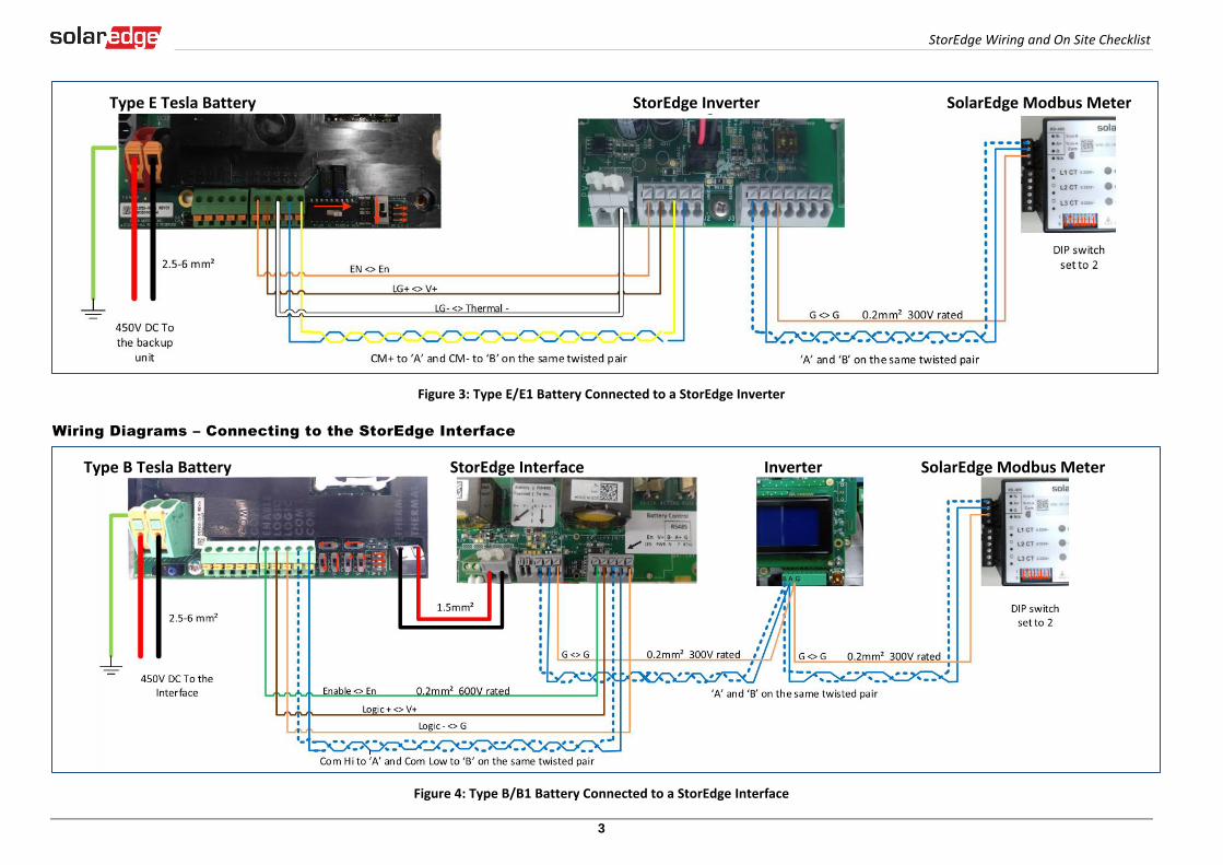
Wiring Diagrams – Connecting to the StorEdge Inverter
Figure 1: Type B/B1 Battery Connected to a StorEdge Inverter
Figure 2: Type C Battery Connected to a StorEdge Inverter
Type B Tesla Battery StorEdge Inverter SolarEdge Modbus Meter
Type C Tesla Battery StorEdge Inverter SolarEdge Modbus Meter
StorEdge Wiring and On Site Checklist
3
Figure 3: Type E/E1 Battery Connected to a StorEdge Inverter
Wiring Diagrams – Connecting to the StorEdge Interface
Figure 4: Type B/B1 Battery Connected to a StorEdge Interface
Type E Tesla Battery StorEdge Inverter SolarEdge Modbus Meter
Type B Tesla Battery StorEdge Interface Inverter SolarEdge Modbus Meter
StorEdge Wiring and On Site Checklist
4
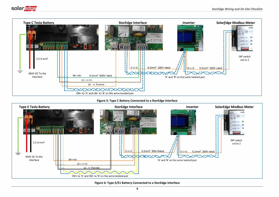
Figure 5: Type C Battery Connected to a StorEdge Interface
Figure 6: Type E/E1 Battery Connected to a StorEdge Interface
Type C Tesla Battery StorEdge Interface Inverter SolarEdge Modbus Meter
Type E Tesla Battery StorEdge Interface Inverter SolarEdge Modbus Meter
StorEdge Wiring and On Site Checklist
5
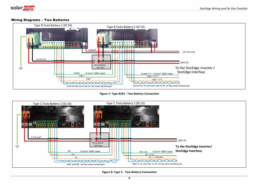
Wiring Diagrams – Two Batteries
Figure 7: Type B/B1 - Two-Battery Connection
Figure 8: Type C - Two-Battery Connection
To the StorEdge Inverter/
StorEdge Interface

StorEdge Wiring and On Site Checklist
6
Figure 9: Type B and Type E - Two-Battery Connection
To the StorEdge Inverter/
StorEdge Interface
To the StorEdge Inverter/
StorEdge Interface

StorEdge Wiring and On Site Checklist
7
Figure 10: Type C and Type E - Two-Battery Connection
Post Installation Verification and Configuration
Follow the checklist below to verify that the systems is properly connected and configured. The checklist is suitable for a system with a single StorEdge Inverter/Interface, a single battery
and a single SolarEdge Modbus Meter installed at the grid connection point (see diagram below). For other system configurations follow the steps in the StorEdge Installation Guide
supplied with the StorEdge Inverter or StorEdge Interface
Figure 11: StorEdge System with StorEdge Inverter (left) and with StorEdge Interface (right)

StorEdge Wiring and On Site Checklist
8
Step Verification Action Checked
1 Installation and Wiring
1.1 Verify the distance between components complies with the distances detailed in the supplied installation guide.
1.2 Take a photograph of the battery thermal controller and send to SolarEdge support (useful for future debugging if necessary.)
1.3 Take a photograph of the StorEdge Interface (if installed) and send to SolarEdge support.
1.4 Take a photograph of the installation and send to SolarEdge support.
1.5 Verify that the battery splash cover is closed.
1.6 Verify that the backed-up loads panel is wired.
1.7 Verify that all DC, communication and AC cabling connections are completed as follows:
1.7.1 Check AC wiring and circuit breaker.
1.7.2 Check string DC input voltage. Expect 1V per optimizer in the string.
1.7.3 Verify that grounding is properly connected in the battery, inverter or StorEdge Interface.
1.7.4 Check DC wiring to the battery (see Table 1). Pull on the connections and verify that all are secured and tight.
1.7.5 For Type B batteries: Check thermal connection to the battery (see Table 1). Pull on the connections and verify that all are secured and tight.
1.7.6 Check connections to the battery including DIP switch setup as described in the supplied installation guide.
1.7.7 Check connections to the meter.
1.7.8 Check connections between the StorEdge Interface and the inverter (if applicable).
1.7.9 Check that a 9V battery is installed in the StorEdge Inverter (if applicable).
1.7.10 Check meter AC and CT connections including CT direction: Connect the meter to power supply. Check the LEDs: when configured as export/import meter: green=import, red=export; when configured as consumption meter LED should be green.
1.7.11 Check connection to the internet with one of the following options: Ethernet, Wi-Fi, Cellular, ZigBee Module.
2 Commissioning
2.1 Switch on the inverter AC.
2.2 Activate the inverter using the SE card.
2.3 Perform pairing when the modules are exposed to sunlight.
2.4 Switch the inverter ON/OFF switch to OFF.
3 RS485 Configuration Verification (for 1 Battery and 1 meter)
3.1 If not already OFF, switch OFF the StorEdge Connection Unit switch (for StorEdge inverter).
3.2 Switch the inverter ON/OFF switch to OFF.
3.3 Devices
StorEdge Wiring and On Site Checklist
9
Step Verification Action Checked
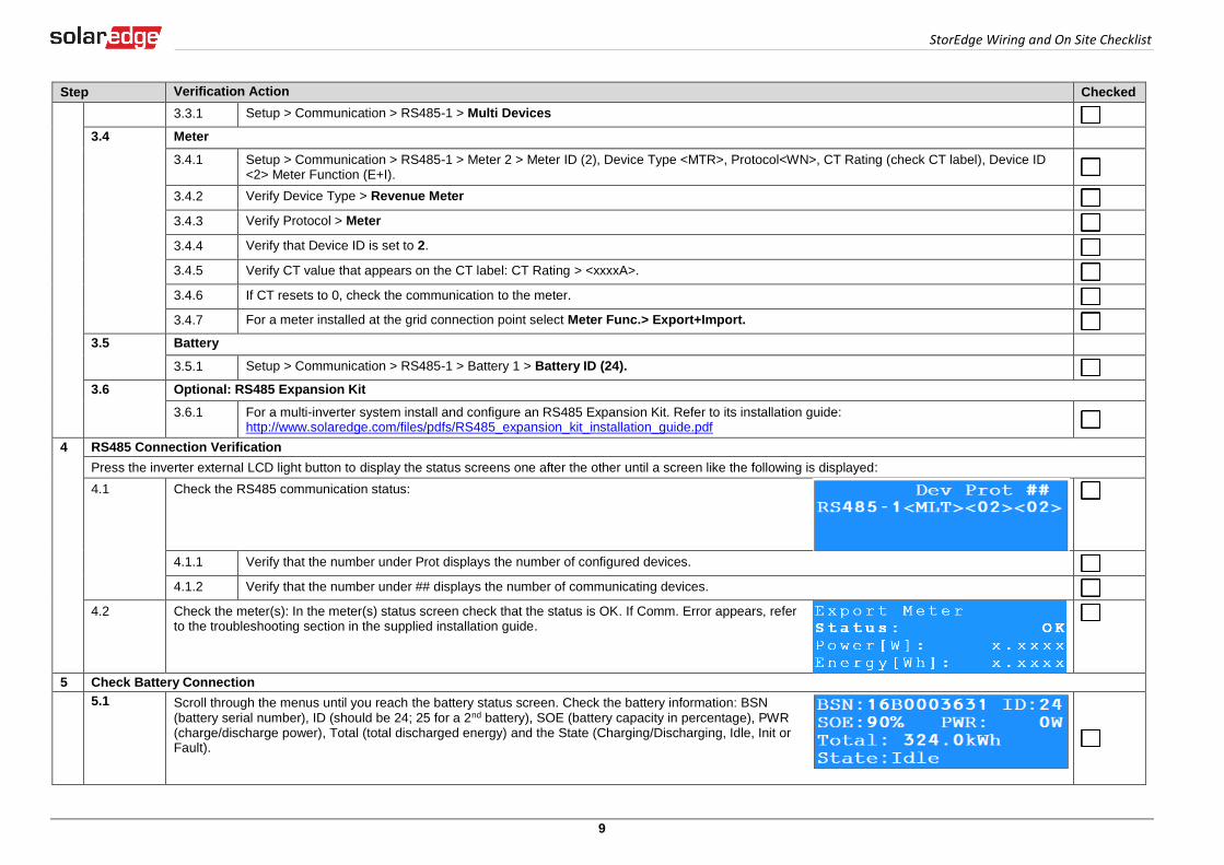
3.3.1 Setup > Communication > RS485-1 > Multi Devices
3.4 Meter
3.4.1 Setup > Communication > RS485-1 > Meter 2 > Meter ID (2), Device Type <MTR>, Protocol<WN>, CT Rating (check CT label), Device ID <2> Meter Function (E+I).
3.4.2 Verify Device Type > Revenue Meter
3.4.3 Verify Protocol > Meter
3.4.4 Verify that Device ID is set to 2.
3.4.5 Verify CT value that appears on the CT label: CT Rating > <xxxxA>.
3.4.6 If CT resets to 0, check the communication to the meter.
3.4.7 For a meter installed at the grid connection point select Meter Func.> Export+Import.
3.5 Battery
3.5.1 Setup > Communication > RS485-1 > Battery 1 > Battery ID (24).
3.6 Optional: RS485 Expansion Kit
3.6.1 For a multi-inverter system install and configure an RS485 Expansion Kit. Refer to its installation guide: http://www.solaredge.com/files/pdfs/RS485_expansion_kit_installation_guide.pdf
4 RS485 Connection Verification
Press the inverter external LCD light button to display the status screens one after the other until a screen like the following is displayed:
4.1 Check the RS485 communication status:
4.1.1 Verify that the number under Prot displays the number of configured devices.
4.1.2 Verify that the number under ## displays the number of communicating devices.
4.2 Check the meter(s): In the meter(s) status screen check that the status is OK. If Comm. Error appears, refer to the troubleshooting section in the supplied installation guide.
5 Check Battery Connection
5.1 Scroll through the menus until you reach the battery status screen. Check the battery information: BSN (battery serial number), ID (should be 24; 25 for a 2nd battery), SOE (battery capacity in percentage), PWR (charge/discharge power), Total (total discharged energy) and the State (Charging/Discharging, Idle, Init or Fault).

StorEdge Wiring and On Site Checklist
10
Step Verification Action Checked
6 Inverter + Battery Firmware Upgrade
6.1 Insert a micro SD card with the latest firmware version available on http://solaredge.com/storedge/firmware.
6.2 Close the inverter cover and the StorEdge Interface cover (if applicable).
6.3 Switch on both the inverter ON/OFF switch and the StorEdge Interface (if applicable).
6.4 Using the external LCD light button go to, Maintenance > SW upgrade > Yes, wait for Running script to finish, duration 5min + 25min per battery.
Battery Firmware Version Check
6.5 Switch OFF the inverter and wait 3 minutes.
6.6 Setup > Communication > RS485-1 > Battery 1 > Battery Info
7 Setup StorEdge Operating Mode
7.1 Turn ON the inverter.
7.2 Check charge or discharge according to the current condition.
7.3 Set up the operating mode according to one of the following options:
Maximize Self Consumption
7.3.1 Setup > Power Control > Energy Manager > Energy Control > Max self-Consume
Charge/Discharge Profile Programming
7.3.2 Setup > Power Control > Energy Manager > Energy Control > Time of Use
Backup Only
7.3.3 Setup > Power Control > Energy Manager > Energy Control > Backup only
7.4 Optional: Set additional StorEdge options
AC Charge
7.4.1 Setup > Power Control > Energy Manager > Storage Ctrl > AC Charge > Enable
Backup reserve
7.4.1 Setup > Power Control > Energy Manager > Storage Ctrl > Backup Rsvd > {Value}

StorEdge Wiring and On Site Checklist
11
Support and Contact Information
If you have technical queries concerning our products, please contact us:
Australia (+61) 1800 465 567 [email protected]
APAC (Asia Pacific) (+972) 073 2403118 [email protected]
China(+86) 21 6212 5536 [email protected]
France and Belgium (+33) 0800 917 410 [email protected]
DACH and Rest of Europe (+49) 089 454 59730 [email protected]
Italy (+39) 800 784 824 [email protected]
Japan (+81) 03 5530 9360 [email protected]
Netherlands (+31) 0800 0221 089 [email protected]
United Kingdom (+44) 0800 028 1183 [email protected]
US & Canada (+1) 510 498 3200 [email protected]
Greece (+30) 00800 125574
Middle East & Africa (+972) 073 2403118
South Africa (+27) 0800 982 659
Turkey(+972) 073 240 3118
Worldwide (+972) 073 240 3118
Before contact, make sure to have the following information at hand:
Inverter and power optimizer model numbers
Serial number of the product in question
The error indicated on the inverter screen or on the SolarEdge monitoring portal, if there is such an indication.
System configuration information, including the type and number of modules connected and the number and length of strings.
The communication method to the SolarEdge monitoring portal, if the site is connected
Inverter software version as appears in the ID status screen.