store models for chemical and sorption storage units - iea shc · pdf filestore models for...
TRANSCRIPT

Store Models for Chemical and Sorption Storage Units A Report of IEA Solar Heating and Cooling Programme - Task 32 Advanced storage concepts for solar and low energy buildings
Report B5 of Subtask B February 2008
Edited by: Chris Bales Contributions from: Dagmar Jaehnig Henner Kerskes Herbert Zondag
Storage Task 32

Store Models of Chemical and Sorption Storage Units
by
Chris Bales (editor)*
Contributions from:
Dagmar Jaehnig, AEE-INTEC, Gleisdorf, Austria Henner Kerskes, ITW, Univ. Stuttgart, Germany
Herbert Zondag, ECN, Holland
A technical report of Subtask B
* Solar Energy Research Center SERC Högskolan Dalarna SE-78188 Borlänge, Sweden

Executive Summary Storage models have been developed for four of the storage concepts that have been studied within Subtask B of IEA-SHC Task 32. These are available from the authors. They are:
1. Thermo-chemical accumulator model for the commercial product ClimateWell 10; 2. detailed model for open adsorption in a zeolite honeycomb structure; 3. simple theoretical model for generic chemical reactions; and 4. closed adsorption store model.
Two of the models have been developed in TRNSYS directly, whereas one has been developed in Matlab and the fourth as a PEDX routine. The latter two models can be linked to TRNSYS and can thus be used in system simulations with the Task 32 boundary conditions. The models vary significantly in detail and require varying degrees of measurements for identifying parameters. For each model, the basic function of the store is described in addition to the model itself. The main assumptions and limitations of each model are stated. Finally details are supplied about the validation of the model. No direct comparison of the models is given as they are of such varying character.
IEA SHC – Task 32 – Advanced storage concepts

IEA Solar Heating and Cooling Programme
The International Energy Agency (IEA) is an autonomous body within the framework of the Organization for Economic Co-operation and Development (OECD) based in Paris. Established in 1974 after the first “oil shock,” the IEA is committed to carrying out a comprehensive program of energy cooperation among its members and the Commission of the European Communities. The IEA provides a legal framework, through IEA Implementing Agreements such as the Solar Heating and Cooling Agreement, for international collaboration in energy technology research and development (R&D) and deployment. This IEA experience has proved that such collaboration contributes significantly to faster technological progress, while reducing costs; to eliminating technological risks and duplication of efforts; and to creating numerous other benefits, such as swifter expansion of the knowledge base and easier harmonization of standards. The Solar Heating and Cooling Programme was one of the first IEA Implementing Agreements to be established. Since 1977, its members have been collaborating to advance active solar and passive solar and their application in buildings and other areas, such as agriculture and industry. Current members are: Australia Finland Portugal Austria France Spain Belgium Italy Sweden Canada Mexico Switzerland Denmark Netherlands United States European Commission New Zealand Germany Norway A total of 39 Tasks have been initiated, 30 of which have been completed. Each Task is managed by an Operating Agent from one of the participating countries. Overall control of the program rests with an Executive Committee comprised of one representative from each contracting party to the Implementing Agreement. In addition to the Task work, a number of special activities—Memorandum of Understanding with solar thermal trade organizations, statistics collection and analysis, conferences and workshops—have been undertaken.
IEA SHC – Task 32 – Advanced storage concepts

The Tasks of the IEA Solar Heating and Cooling Programme, both underway and completed are as follows: Current Tasks: Task 32 Advanced Storage Concepts for Solar and Low Energy Buildings Task 33 Solar Heat for Industrial Processes Task 34 Testing and Validation of Building Energy Simulation Tools Task 35 PV/Thermal Solar Systems Task 36 Solar Resource Knowledge Management Task 37 Advanced Housing Renovation with Solar & Conservation Task 38 Solar Assisted Cooling Systems Task 39 Polymeric Materials for Solar Thermal Applications Completed Tasks: Task 1 Investigation of the Performance of Solar Heating and Cooling Systems Task 2 Coordination of Solar Heating and Cooling R&D Task 3 Performance Testing of Solar Collectors Task 4 Development of an Insolation Handbook and Instrument Package Task 5 Use of Existing Meteorological Information for Solar Energy Application Task 6 Performance of Solar Systems Using Evacuated Collectors Task 7 Central Solar Heating Plants with Seasonal Storage Task 8 Passive and Hybrid Solar Low Energy Buildings Task 9 Solar Radiation and Pyranometry Studies Task 10 Solar Materials R&D Task 11 Passive and Hybrid Solar Commercial Buildings Task 12 Building Energy Analysis and Design Tools for Solar Applications Task 13 Advance Solar Low Energy Buildings Task 14 Advance Active Solar Energy Systems Task 16 Photovoltaics in Buildings Task 17 Measuring and Modeling Spectral Radiation Task 18 Advanced Glazing and Associated Materials for Solar and Building Applications Task 19 Solar Air Systems Task 20 Solar Energy in Building Renovation Task 21 Daylight in Buildings Task 23 Optimization of Solar Energy Use in Large Buildings Task 22 Building Energy Analysis Tools Task 24 Solar Procurement Task 25 Solar Assisted Air Conditioning of Buildings Task 26 Solar Combisystems Task 28 Solar Sustainable Housing Task 27 Performance of Solar Facade Components Task 29 Solar Crop Drying Task 31 Daylighting Buildings in the 21st Century Completed Working Groups: CSHPSS, ISOLDE, Materials in Solar Thermal Collectors, and the Evaluation of Task 13 Houses To find Solar Heating and Cooling Programme publications and learn more about the Programme visit www.iea-shc.org or contact the SHC Executive Secretary, Pamela Murphy, e-mail: [email protected] September 2007
IEA SHC – Task 32 – Advanced storage concepts

What is IEA SHC Task 32 “Advanced Storage Concepts for solar and low energy buildings” ?
The main goal of this Task is to investigate new or advanced solutions for storing heat in systems providing heating or cooling for low energy buildings.
o The first objective is to contribute to the development of advanced storage solutions in thermal solar systems for buildings that lead to high solar fraction up to 100% in a typical 45N latitude climate.
o The second objective is to propose advanced storage solutions for other heating or cooling technologies than solar, for example systems based on current compression and absorption heat pumps or new heat pumps based on the storage material itself.
Applications that are included in the scope of this task include:
o new buildings designed for low energy consumption o buildings retrofitted for low energy consumption.
The ambition of the Task is not to develop new storage systems independent of a system application. The focus is on the integration of advanced storage concepts in a thermal system for low energy housing. This provides both a framework and a goal to develop new technologies.
The Subtasks are:
o Subtask A: Evaluation and Dissemination o Subtask B: Chemical and Sorption o Subtask C: Phase Change Materials o Subtask D: Water tank solutions
Duration
July 2003 - December 2007.
www.iea-shc.org look for Task32
IEA SHC – Task 32 – Advanced storage concepts

IEA SHC Task 32 Subtask B “Chemical and Sorption Storage” This report is part of Subtask B of the Task 32 of the Solar Heating and Cooling Programme of the International Energy Agency dealing with solutions of storage based on adsoprtion or absorption processes and on thermochemical reactions. This report presents new simulation models that were developped by Task 32 participants for the purpose of understanding how an advanced storage concept can be best integrated into a solar combisystem and what performances of such a system one can expect. Due to the difficulty of maintaining a simulation model it has been decided that all pieces of software developped within Task 32 are available only through their authors. In case of interest, the reader should contact the author of the storage model directly. The Operating Agent would like to thank the authors of this document for their implication in the search of future storage solutions for solar thermal energy, the key to a solar future for the heating and cooling of our buildings.
Jean-Christophe Hadorn Operating Agent of IEA SHC Task 32 for the Swiss Federal Office of Energy BASE Consultants SA - Geneva [email protected]
NOTICE: The Solar Heating and Cooling Programme, also known as the Programme to Develop and Test Solar Heating and Cooling Systems, functions within a framework created by the International Energy Agency (IEA). Views, findings and publications of the Solar Heating and Cooling Programme do not necessarily represent the views or policies of the IEA Secretariat or of all its individual member countries.
IEA SHC – Task 32 – Advanced storage concepts

Contents
1 INTRODUCTION 1
1.1 Scope 1
2 TCA HEAT STORAGE UNIT 2
2.1 Description of Process and Operating Principles 2
2.2 Model Description 4
2.2.1 Switching Unit and Controller 4
2.2.2 Single TCA Unit 5
2.3 Parameter Identification and Verification 6
2.4 Acknowledgements 8
2.5 References 8
3 CLOSED CYCLE SORPTION HEAT STORAGE UNIT 9
3.1 Description of Process and Operating Principles 9
3.2 Model Description 10
3.2.1 Adsorber Model 10
3.2.2 Evaporator/Condenser Model 13
3.2.3 Assumptions and Limitations 14
3.3 Parameter Identification and Verification 14
3.4 Acknowledgements 15
3.5 References 15
IEA SHC – Task 32 – Advanced storage concepts

4 ECN TCM HEAT STORAGE MODEL 16
4.1 Description of Process and Operating Principles 16
4.2 Model Description 17
4.3 Parameter Identification and Verification 17
4.4 Acknowledgements 18
4.5 References 18
5 MONOSORP HEAT STORAGE UNIT 19
5.1 Description of Process and Operating Principles 19
5.2 Model Description 20
5.3 Parameter Identification and Verification 21
5.4 References 21
IEA SHC – Task 32 – Advanced storage concepts

1
1 INTRODUCTION Four different storage units using thermo-chemical and sorption technology have been simulated within Subtask B. A summary of these is given in Table 1.1. The models are described in the following chapters, one for each model.
Table 1.1: Summary of simulation models for storage units developed in Subtask B.
Type of Technology Model Type Investigating Institute
Closed three phase absorption (TCA)
Physical (material properties, masses) Empirical (heat exchangers, heat losses)
Solar Energy Research Center SERC, Sweden
Open adsorption Physical (material properties, masses) ITW, Univ. Stuttgart, Germany
Closed adsorption Physical (material properties, masses) Empirical (heat exchangers, heat losses) AEE INTEC, Austria
Closed two phase thermo-chemical
Simplified model with idealised material properties ECN, Holland
1.1 Scope The scope of the storage unit model includes all heat exchangers and other components necessary for the process of heat storage and extraction but does not include the components for interaction with external circuits such as heat sources/sinks, loads etc. Models for control functions and necessary switching units are also described. The detailed mathematical model is not given here, rather the main principles of the model, together with a reference to the mathematical model. The main assumptions and limitations of the model are described. A brief summary is also given of how parameters for the models have been identified and verified.
IEA SHC – Task 32 – Advanced storage concepts
2
2 TCA HEAT STORAGE UNIT Chris Bales, SERC, Högskolan Dalarna, Sweden These models are available from the author as standalone DLL’s for use with TRNSYS 16.1 together with the full documentation of the models.
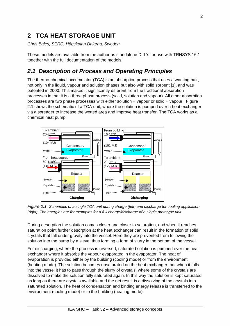
2.1 Description of Process and Operating Principles The thermo-chemical accumulator (TCA) is an absorption process that uses a working pair, not only in the liquid, vapour and solution phases but also with solid sorbent [1], and was patented in 2000. This makes it significantly different from the traditional absorption processes in that it is a three phase process (solid, solution and vapour). All other absorption processes are two phase processes with either solution + vapour or solid + vapour. Figure 2.1 shows the schematic of a TCA unit, where the solution is pumped over a heat exchanger via a spreader to increase the wetted area and improve heat transfer. The TCA works as a chemical heat pump.
Pump From heat source 60-110°C (140 MJ)
To ambient 20-35°C (104 MJ)
Water
Condensor / Evaporator
From building10-17°C
(101 MJ)
Vapour Vapour
Condensor / Evaporator Water
Pump To ambient 20-35°C (122 MJ)
Reactor
Filter
Crystals
Solution
Reactor
Figure 2.1. Schematic of a single TCA unit during charge (left) and discharge for cooling application (right). The energies are for examples for a full charge/discharge of a single prototype unit.
During desorption the solution comes closer and closer to saturation, and when it reaches saturation point further desorption at the heat exchanger can result in the formation of solid crystals that fall under gravity into the vessel. Here they are prevented from following the solution into the pump by a sieve, thus forming a form of slurry in the bottom of the vessel.
For discharging, where the process is reversed, saturated solution is pumped over the heat exchanger where it absorbs the vapour evaporated in the evaporator. The heat of evaporation is provided either by the building (cooling mode) or from the environment (heating mode). The solution becomes unsaturated on the heat exchanger, but when it falls into the vessel it has to pass through the slurry of crystals, where some of the crystals are dissolved to make the solution fully saturated again. In this way the solution is kept saturated as long as there are crystals available and the net result is a dissolving of the crystals into saturated solution. The heat of condensation and binding energy release is transferred to the environment (cooling mode) or to the building (heating mode).
Disharging
Pump Filter
Crystals
Solution
Pump
Charging
IEA SHC – Task 32 – Advanced storage concepts

3
The process can, however, be restricted to work in the two phase region during charging to avoid unwanted crystallisation in pipes etc, but crystals will form when the solution is cooled down during discharge, thus operation can be two-phase during charge and three-phase during discharge. Discharge is normally extended beyond the point where all crystals have been dissolved, thus the first part will be in three-phase region and the rest in two-phase region.
More details can be found in [2] and [3].
The TCA has the following characteristics:
High energy density storage in the solid crystals.
Good heat and mass transfer, as this occurs with solution.
As the process is essentially a batch process, two identical units are used together with a switching unit in order to be able to charge and discharge at the same time. This complete heat pump/storage machine is being commercialised by the company ClimateWell AB under the name ClimateWell 10, and is designed for solar heating and cooling applications with a rated cooling rate of 10 kW. For applications where there is only a heat load, a single unit can be used. In the later prototypes and pre-commercial production, the heat exchangers for condensation/evaporation of water and for sorbing/desorbing water to/from the solution are in separate vessels, whereas the bulk water and solution is kept in other vessels (see figure 2.1). There is a flow between these bulk stores and heat exchange vessels.
Solution vessel
Water vessel
Reactor
Condensor / Evaporator
Figure 2.2. CAD drawing (left) of a prototype single TCA unit (left) with separate vessels for heat exchange (reactor and condensor/evaporator) and bulk storage of water and solution. Picture (right) of ClimateWell 10 product with two identical units and a switching unit above. Source: ClimateWell AB.
IEA SHC – Task 32 – Advanced storage concepts

4
2.2 Model Description There are two separate models that are required for the full quasi-continuous process: single TCA unit (type 215) and switching unit and controller (type 216). These model are described in detail by Nordlander and Bales [5,6]. These models have been further developed from the models of the prototype machines previously published [2], and reflect the performance and construction of the machine as commercialised during 2007. The main points are summarised here: The main assumptions of the models are:
The heat transfer coefficient between the reactor and condenser (internal losses) during discharge are assumed to be 30% of those during charge.
The heat transfer coefficients for the heat exchangers are only dependent on whether the unit is charging or discharging and not on temperature, flow and solution concentration.
The model is a semi-empirical model. The material properties for the LiCl/water working pair are derived from the correlations of Conde [4] and are fixed, the masses are the physical quantities and the heat exchange/heat loss coefficients have to be derived from measurements. The main limitations of the model are:
A single UA value is used for charge and one for discharge. The individual UA values for condenser and reactor heat exchangers are determined with fixed ratios from these values. The model does not take into account two phase conditions on the heat exchangers in detail.
Not all control functions in the current controller are modelled. Several of these have functions are “safety” features that hinder unwanted crystallisation.
No calculation of internal electrical use is made.
2.2.1 Switching Unit and Controller This TRNSYS model (Type 216) models the switching unit that switches flow between the external circuits and the heat exchangers in the two TCA units, as well as the controller for the machine. There are two operation modes: heating mode, when the machine will provide heat to a distribution circuit, heat pumped from a low temperature heat source; and cooling mode where cooling is supplied to the distribution system and heat will be rejected to one or two external circuits. There are two swapping modes: normal mode, where the units swap when only one of the units has become empty (fully discharged) or full (fully charged); full cycles, where the units swap only after both the units are either empty or full. The former is the default. There are two different possibilities for connection to external circuits: four circuits, where there is one circuit connected to each of the four heat exchangers in a full machine; three circuits where two heat exchangers are connected to one of the external circuits, dependent on whether the machine is heating or cooling mode.
IEA SHC – Task 32 – Advanced storage concepts

5
The definition of fully charged and discharged is based on an algorithm devised by the ClimateWell and is not described in detail as it is proprietary. However, the threshold values for full and empty are defined as parameters.
2.2.2 Single TCA Unit This TRNSYS model (Type 215) is a dynamic model of a single TCA unit (also called barrel). It consists of a reactor and condenser/evaporator with a vapour channel between them, as well as stores for both water and the active salt (solution store), which can contain both solution and solid monohydrate crystals (see Figure 2.3). The model is restricted to LiCl solution. Vacuum conditions are assumed. Each of the main sections (4) has its own mass and associated heat loss coefficient and there is a “heat loss” coefficient governing heat transfer directly between reactor and condenser. The masses of the water and solution stores change dependent on the degree of charge of the unit. Heat of vaporisation, condensation and dilution is taken into account as are sensible heat gains/losses. A single UA-value is used as parameter for charge and one for discharge conditions, and this is used to calculate the UA-values for the reactor and condenser heat exchangers. The pressure drop for the vapour transport during discharge is calculated based on the mass flow and is used to calculate a effective temperature difference during operating conditions. There is a mixing flow between the reactor and solution store, and between condenser and water store. The model uses a fixed number of internal time steps for every TRNSYS time step, in order to iterate to a solution.
Condenser/evaporator Mce, Tce
Reactor Mre, Tre
Mssre, Mwsre
Solution store Mss, Tss
Mmcss, Mssss, Mwsss
Water store Mws, Tws
mcx, Tcxo
mcx, Tcxi
mrx, Trxo
Qrxmrx, Trxi
mc
mr
mvap
Qcx
Figure 2.3. Schematic of the single TCA unit model for TRNSYS.
IEA SHC – Task 32 – Advanced storage concepts

6
The temperature difference between the inlet fluid to the reactor and that to the condenser is dependent on the theoretical properties of the material pair (LiCl-water) using data published by Conde [4] and the overall heat transfer coefficients of the two heat exchangers. One UA-value is defined for charging and another for discharging, and the individual ones for the reactor / condenser are derived from these. The model calculates the required vapour flow, and hence heating/cooling rates, to maintain a user given supply temperature during discharge. If the cooling/heating capacity is not sufficient to meet this desired temperature, then the full capacity and resulting temperatures are used.
2.3 Parameter Identification and Verification Several ClimateWell 10 machines were tested over a period of several weeks during April – July 2007 at the ClimateWell testing lab after an initial calibration of the measurement equipment. The tests were performed after each machine had been loaded with salt and tested for compliance with the internal quality control of the company, and before each machine was delivered for installation. The resulting model parameters are thus for an “average” machine of those tested. The test sequences were made at for constant boundary conditions of charging and discharging power and temperature supply to condenser, but with different boundary conditions for the different test sequences. The controller/switching unit was not connected during these tests. The main parameters concerning the masses and properties of water and Lithium Chloride were fixed to those of the physical quantities. The parameters for heat loss coefficients to ambient were derived using energy balances for a single unit from one machine for one complete cycle, making sure that the start and end conditions of the cycles were the same, ensuring as well as possible that the internal energy of the unit was the same at start and end. Using a simulation model of the whole machine with the same boundary conditions as the tests, the internal heat loss coefficient was estimated so as that the COP of the simulated machine was similar to that of the measured value. Thereafter an automatic parameter identification was performed using the tools DF [7] and Fittrn [8] together with TRNSYS and the measured data sequences. The main parameters for the model are given in Table 3.1. No scaling of the model has been made. The parameter values for the controller model are those defined by ClimateWell for normal operation of the machine. They have not been verified against actual performance of the machine as the tests were not performed using the normal controller.
IEA SHC – Task 32 – Advanced storage concepts

7
Table 3.1. Main parameter values identified for the commercial ClimateWell 10 units tested.
Parameter Description Value Identification
UAre – heat loss coefficient for reactor 8.6 [W/K] From energy balance UAce – heat loss coefficient for condenser 8.6 [W/K] From energy balance UAss – heat loss coefficient for solution store 9.2 [W/K] From energy balance UAws – heat loss coefficient for condenser 9.2 [W/K] From energy balance UAint – heat transfer coefficient between reactor and condenser during charge 16.7 [W/K] From COP test
UAch – heat transfer coefficient for charging 1000 [W/K] TRNSYS + DF UAdi – heat transfer coefficient for discharging 4230 [W/K] TRNSYS + DF fdp – pressure drop factor for vapour flow 9.62 [-] TRNSYS + DF mr – internal circulation flow of solution 0.278 [kg/s] TRNSYS + DF mc – internal circulation flow of water 0.225 [kg/s] TRNSYS + DF Figure 2.4 shows the measured and simulated values of heat transfer rate for the reactor and condenser of a single unit over two full cycles. The agreement is in general good except at the start of the charging or discharging phases where the simple model for heat transfer rate is a limiting factor. In reality, during the initial phase of the charge in the reactor, there is only sensible heat transfer, and desorption only starts when the temperature is high enough. The desorption starts earlier in the model.
Condenser simulated
Condenser measured
Reactor simulated
Reactor measured
Figure 2.4. Measured and simulated heat transfer rates for the reactor and condenser for two full cycles of a single unit.
IEA SHC – Task 32 – Advanced storage concepts

8
2.4 Acknowledgements The work reported here has been financed by the Swedish National Energy Agency through the projects P21241-1 and P21543-1.
2.5 References 1. Olsson, R., M. Kaarebring-Olsson, and S. Jonsson, A Chemical Heat Pump, in World
Patents Register. 2000.
2. Bales, C. and S. Nordlander, SERC report ISRN DU-SERC--91--SE: TCA EVALUATION - Lab Measurements, Modelling and System Simulations, SERC, Högskolan Dalarna, Borlänge, Sweden.www.serc.se. 2005.
3. Hadorn, J.-C., ed. Thermal Energy Storage for Solar and Low Energy Buildings .- State of the Art. 2005, Lleida University: Lleida, Spain. ISBN: 84-8409-877-X.
4. Conde, M.R., Properties of aqueous solutions of lithium and calcium chlorides: formulations for use in air conditioning equipment design. International Journal of Thermal Sciences, 2004. 43(4).
5. Nordlander, S., C. Bales, Type 215 – ClimateWell 10 Barrel Model Description, SERC, Högskolan Dalarna, 2007. www.serc.se.
6. Nordlander, S., C. Bales, Type 216 – ClimateWell 10 Controller Model, SERC, Högskolan Dalarna, 2007. www.serc.se.
7. Spirkl, W., DF - Dynamic Systems Testing. 1999, In-Situ Scientific Software: Germering, Germany.
8. Huber, C., Fittrn / DF - TRNSYS Parameter identification with DF for Windows 95 / NT. 1998, SPF-HSR, Rapperswil, Switzerland: Rapperswil, Switzerland.
IEA SHC – Task 32 – Advanced storage concepts

9
3 CLOSED CYCLE SORPTION HEAT STORAGE UNIT Dagmar Jaehnig, AEE INTEC, Austria The model is available from the author. However, there is no documentation available yet.
3.1 Description of Process and Operating Principles A closed sorption heat store is in fact a thermo-chemical heat pump which is operated under vacuum conditions. This allows evaporation at a low temperature level and water vapour transport without the need of a pump or fan. The basic principle is described below and shown in Figure 3.1: 1. Charging process (desorption, drying of adsorbent): Heat from a high temperature source (solar thermal collectors) is fed into the device, heats the adsorbent and vapor is desorbed from the adsorbent. The desorbed vapor is condensed at a lower temperature level and then pumped out of the container into a separate reservoir. The heat of condensation has to be withdrawn to the environment. 2. Storage period: The dry adsorbent is separated from the liquid working fluid (the connecting valve is closed). As long as these components stay separate, long-term heat storage without losses is possible if the sensible heat involved is neglected. 3. Discharging process (adsorption of working fluid on adsorbent): Water is pumped into the evaporator where it evaporates taking up heat at a low temperature level. The vapor is adsorbed and releases the adsorption heat at a higher temperature level. This is the useful heat that can be used for space heating.
High temperatureheat
DesorptionCharging Condensation
Water vapor Low temperature heat
High temperatureheat
AdsorptionDischarging
Water vapor Low temperature heat
Storage Dry silicagel
Liquidwater
Evaporation
Figure 3.1. Working principle of a closed-cycle adsorption heat store.
Within the framework of the EU-Project MODESTORE, a prototype storage module has been developed (Figure 3.2). The upper part contains the adsorber and a spiral heat exchanger. In the centre, there is a vertical channel for vapor diffusion. The spiral heat exchanger consists of perforated sheet copper with copper pipes soldered to it. The lower part contains the heat exchanger that serves as evaporator and condenser. At the bottom, the container is connected to a second container that holds the water that is not adsorbed. For desorption the water is pumped from the storage module as it accumulates at the bottom. For adsorption, water is led into the bottom of the storage container and heated.
IEA SHC – Task 32 – Advanced storage concepts

10
The advantage of the new design is that it is very compact. All major components (adsorber and evaporator/condenser heat exchanger) are included in a single container. The distances between adsorber and evaporator/condenser are very short. The vapor does not have to pass through narrow pipes which reduces the pressure losses.
Figure 3.2. Prototype storage module.
The tested prototype store contained approximately 200 kg of silica gel.
3.2 Model Description The sorption store has been modelled using three separate models in TRNSYS. The adsorber part is modelled as a simple energy and mass balance. The heat exchanger in the adsorber is modelled as an external heat exchanger (standard Type 5). In addition, a new heat exchanger model was written for the evaporator/condenser heat exchanger. The two new TRNSYS Types are described in the following sections.
3.2.1 Adsorber Model The adsorber is modelled with a simple energy and mass balance. The adsorber is described using a single node and therefore constant temperature and water content.
IEA SHC – Task 32 – Advanced storage concepts

11
The mass balance is quite simple. The change of the variable of state (water content of adsorber) is equal to the water vapour evaporated or condensed in that timestep. The water vapour is calculated from the transferred power at the evaporator/condenser heat exchanger.
steamA m
dtmxd •
=⋅ )(
where x water content of adsorber mA mass of dry adsorber
Smgas
∆ x Figure 3.3. Mass balance of adsorber
The energy balance says that the change in internal energy is equal to all heat inputs and outputs to and from the adsorber, some of which depend on the water content.
losssorpadjadsdesCollloadA QWQQQQQ
dtdU
−+−+−+−=
where Qload heat that goes to the load during discharge Qcoll heat of charging, for example from solar thermal collectors Qdes heat that leaves the adsorber with the desorbed water vapor (internal
energy of the vapour) Qads heat that comes into the adsorber with the adsorbed water vapor (internal
energy of the vapour) Qadj additional term that is used if the temperature of the water vapor entering
the adsorber is not equal to the adsorber temperature Wsorp heat of adsorption that is generated in the adsorber during adsorption and
is consumed during desorption (characteristic curve of sorption material used)
Qloss heat losses from the sorption store to the surroundings From the internal energy, the temperature of the adsorber can be calculated.
waterpAApA
AA cmxcm
UT,, ⋅⋅+⋅
=
IEA SHC – Task 32 – Advanced storage concepts

12
S
∆ Us
Um
Qads
Qloss
Qload
Qcoll
Figure 3.4. Energy balance of adsorber.
The parameters, inputs outputs and derivatives of the model are listed in the table below. Remarks Model Parameters:
mA kg Mass of sorption material cp,water kJ/kg.K Specific heat capacity of water cp,sorp kJ/kg.K Specific heat capacity of sorption material Model Inputs: Qload kW heat that goes to the load during discharge Qdes kW heat that leaves the adsorber with the desorbed water vapor
(internal energy of the vapour) Qads kW heat that comes into the adsorber with the adsorbed water vapor
(internal energy of the vapour) QColl kW heat of charging, for example from solar thermal collectors Qadj kW additional term that is used if the temperature of the water vapor
entering the adsorber is not equal to the adsorber temperature Wsorp kW heat of adsorption that is generated in the adsorber during
adsorption and is consumed during desorption (characteristic curve of sorption material used)
Qloss kW heat losses from the sorption store to the surrounding msteam kg/hr steam flow to/from condenser/evaporator Model Outputs TA °C Temperature of the Adsorber x_mA kg Product of mass of sorption material and water content DeltaU kW Change in internal energy of sorption store per timestep Model Derivatives
Uini kJ Initial value of internal energy of sorption store xmAini kg Initial value of the product of mass of sorption material and water
content
IEA SHC – Task 32 – Advanced storage concepts

13
3.2.2 Evaporator/Condenser Model The evaporator / condenser heat exchanger is modelled with a logarithmic temperature difference model. On the primary side of the heat exchanger (Tin, Tout) there is a temperature change from inlet to outlet. On the secondary side evaporation or condensation takes place, therefore, the temperature on that side stays constant (Tvap). The outlet temperature on the primary side of the heat exchanger can then be calculated with the following equation:
vap
cm
UAvapin
out T
e
TTT
waterpin
+−
=•
,
where Tout outlet temperature on primary side Tin inlet temperature on primary side Tvap temperature of water vapour on secondary side
mass flow rate of condensed or evaporated water vapour inm•
cp,water specific heat of heat transfer fluid on primary side UA heat transfer coefficient of heat exchanger
and the transferred power can be calculated using the following equation •
••
⋅⋅−= inwaterpinout mcTTQ ,)(
This value is then used as input to the adsorber model. The parameters, inputs outputs and derivatives of the model are listed in the table below. Remarks Model Parameters:
cp,water kJ/kg.K Specific heat capacity of water Model Inputs: Tvap °C temperature of water vapour on secondary side Tin °C inlet temperature on primary side
inm•
kg/hr mass flow rate of condensed or evaporated water vapour
UA W/K heat transfer coefficient of heat exchanger Model Outputs:
Tout °C outlet temperature on primary side Qdot kW transferred power by condenser/evaporator
IEA SHC – Task 32 – Advanced storage concepts

14
3.2.3 Assumptions and Limitations The model is a semi-physical model with a few parameters that have to be determined with parameter identification from measured data. These parameters are the UA-values for the heat exchangers (adsorber and evaporator/condenser) and a UA-value for the sensible heat losses from the sorption storage tank to ambient. Otherwise it is based on energy and mass balances and the physical properties of the sorption material. The main assumptions of the model are:
single node model
no time dependency of adsorption and desorption processes The main limitations of the model are: (including known validity limitations) Up and downscaling cannot be done easily because the UA-values of the heat exchangers and for the store heat losses have to be derived from measurements. For the task 32-simulations reasonable assumptions have been made.
3.3 Parameter Identification and Verification The model was validated with data from laboratory tests of a small prototype system and using 200 kg of silica gel Grace 127B as sorption material. The model consists of only three model parameters, UA-value of the adsorber heat exchanger, UA-value of the evaporator/condenser heat exchanger and the UA-value for the heat losses from the store to ambient, as well as the characteristic curve of the adsorber material. The characteristic curve was taken as given from measurement results of the material itself. The other three parameter were fitted using test sequences. Inputs were the inlet temperatures of the heat exchangers, the ambient temperature and the initial values of adsorber temperature and water content. The outputs that had to fit with the measured values were the outlet temperature of the heat exchangers, the average silica gel temperature, the water content of silica gel and the power transferred across the heat exchangers. The following figures show the measured and calculated values for an adsorption process. The values fit reasonably well.
Temperature silica gel
Outlet temperature condenser
Outlet temperature silica gel hx
Temperature silica gel
Outlet temperature condenser
Outlet temperature silica gel hx
Water content of silica gelWater content of silica gel
IEA SHC – Task 32 – Advanced storage concepts

15
Figure 3.5: Validation sequence (adsorption)
3.4 Acknowledgements The work reported here has been financed by the European Commission (contract number NNE5/2001/979) and the Austrian Ministry of Transport, Innovation and Technology and the Austrian companies Solution Solartechnik and Pink Behältertechnik as part of the project MODESTORE within the research program ‘Haus der Zukunft (Building of Tomorrow)’.
3.5 References 1. Hadorn, J.-C., ed. Thermal Energy Storage for Solar and Low Energy Buildings .- State
of the Art. 2005, Lleida University: Lleida, Spain. ISBN: 84-8409-877-X.
IEA SHC – Task 32 – Advanced storage concepts

16
4 ECN TCM HEAT STORAGE MODEL Herbert Zondag, ECN, the Netherlands
4.1 Description of Process and Operating Principles The ECN Themo-Chemical Materials (TCM) heat storage system is an absorption process that is based on the hydration of a solid TCM salt. At this moment, the development of this system is still in a very early stage and the research focuses on materials characterisation (at present it mainly focuses on the hydration of MgSO4 powder). The outlook for the future is to develop a seasonal storage for solar heat with a solid absorption material. This material is still to be selected. A schematic presentation of the ECN TCM heat storage system is given in Figure 4.1. The charging of the store involves the endothermic dehydration of the salt (C) in the dissociation reactor to a dehydrated salt (powder, B) and water vapour which is condensed (A), the condensation energy being rejected to a borehole. There is a net flow of material from the storage vessel for the hydrated salt to the separate vessels for the dehydrated salt and condensed water. The discharge of the store, used for space heating and DHW, utilises the exothermic hydration in the association reactor of the salt by water vapour that has been evaporated using heat from the borehole. The TCM storage system thus works as a chemical heat pump, but with a very large internal storage capacity. In the discharge phase there is a net flow of material from the separate storage vessels (A, B) to the store for the hydrated salt (C). The process thus requires “pumping” of powder between the vessels and the reactors.
Figure 4.1: Schematical presentation of ECN TCM heat storage unit. LEFT: first set of calculations, RIGHT: second set of calculations
Since the research is still in the phase of materials research, and no (sub)system measurements have been carried out, many critical parameters are at present still unknown. In particular, neither the characteristics of the material still-to-be-selected, nor the designs of the hydration and dehydration reactors are known, including parameters such as power delivered or parasitic energy use. Therefore, for the first calculations, a basic system was
IEA SHC – Task 32 – Advanced storage concepts

17
modelled with a storage capacity of 4 to 6 GJ, that can supply any power required and for which all parasitic energy use was ignored.
4.2 Model Description The TCM model was set up in Matlab, and was coupled to TRNSYS by means of a TRNSYS type 155. The model is very basic and has as parameters the enthalpy and entropy per mole of water of the reaction step and the heat capacity of hydrated and dehydrated salt. The model allows multiple (de)hydration steps and assumes infinitely fast kinetics and ideal heat- and vapour transport within the reactor, as well as ideal transport of the solid material between reactor and storage. After charging, all sensible heat is lost. During discharging, all sensible heat in the newly formed hydrate is used (preheating). The thermal capacity of the reactor itself is ignored. For the material used in the tank, a fictitious TCM hydrate material S was taken and energy was stored by means of the reaction S + nH2O SxnH2O Where n, as well as the enthalpy change ∆H and entropy change ∆S per molecule of water for the hydration and dehydration reactions are quantities that have to be specified in the model. ∆S was chosen to be 150 J/mol/K (a realistic value for hydrates), while ∆H was chosen such that the system would be able to heat the water to the required temperature level, also at low borehole temperatures (roughly about 65 kJ/mol). Two sets of calculations were carried out:
1. The first set of calculations was carried out in April 2007. An ideal borehole was used that could supply an infinite amount of 10 °C water to the TCM evaporator / condenser. The enthalpy change ∆H was assumed to be 61 kJ/mol, resulting in a load temperature a little over 50 °C and T_unload was assumed to be 50 °C. A 4 GJ TCM storage was used for a 13 month simulation period.
2. The second set of calculations was carried out in January 2008. In this case, the choice was made to feed the water tank of the solar heating system from the TCM storage (see Figure 4.1, right). Also, instead of the ideal borehole, the TES type 557 borehole model was used (no ground preheating was applied). Since the borehole temperature was now subject to change, resulting in a varying vapour pressure and a corresponding varying reaction equilibrium temperature, a slightly different enthalpy change ∆H of 66 kJ/mol was used to make sure that the equilibrium temperature would not get below the 63 °C setpoint of the water tank. It was assumed that 3 moles of water could be attached per mole of salt and the resulting TCM storage capacity was 6.6 GJ. The simulation time was increased to two years.
4.3 Parameter Identification and Verification Since a prototype has not yet been built and an idealised TCM system was modelled, no parameter identification and validation has taken place.
IEA SHC – Task 32 – Advanced storage concepts

18
4.4 Acknowledgements This project has received financial support from the Dutch Ministry of Economic Affairs by means of the EOS support scheme. The work on thermochemical heat storage is part of the long-term work at ECN on compact storage technologies.
4.5 References 1. Zondag, H.A. (2007), First FSC results, presentation at IEA task 32 meeting in
Stuttgart.
IEA SHC – Task 32 – Advanced storage concepts

19
5 MonoSorp HEAT STORAGE UNIT Henner Kerskes, Institute for Thermodynamics and Thermal Engineering (ITW),
University of Stuttgart, Pfaffenwaldring 6, 70550 Stuttgart, Germany This model is available from the author.
5.1 Description of Process and Operating Principles Figure 1 shows the schematic of a solar operated space heating system for a residential building with and without sorption storage. To the conventional “combi storage” system (Figure 5.1a: combi-storage of 1000 l with 20 m2 of evacuated tube collectors), a “sorption storage” with a volume of 7.85 m3 is added to the system (as seen in Figure 5.1b). The wet ambient air supplies the required moisture to achieve adsorption space heating. The existing controlled ventilation of the building generates the idea of integrating an adsorption-bed between the indoor air leaving the space heating zone and the heat recovery unit.
In winter, the indoor air at room temperature (~ 20°C) is allowed to pass through the sorption storage. The adsorbent adsorbs the moisture from the air and in turn heats up (gaining heat of adsorption) significantly above 20°C. This warm air is then allowed to pass through the heat exchanger (HX1), where it heats the incoming fresh ambient air (processed air) which in turn heats the building. Thus, the space heating continues until the sorption system gets saturated (by the end of the winter season) with water vapour.
Figure 5.1: Schematic sketch of a solar equipped residential building with mechanical ventilation system with heat recovery and sorption storage
b a
IEA SHC – Task 32 – Advanced storage concepts

20
Since the wet ambient air is used as the “water vapour carrier”, only an “open cycle” mode is possible. Compared to the usually employed packed beds, a major improvement was achieved by the application of zeolite honeycomb structures which have additional advantages when used in sorption storage systems. These regularly shaped bodies include a large number of small straight channels (Figure 5.2), which minimizes the pressure drop when operated in “open cycle” mode. As described by Hammer [4], these structures can produce higher adsorption performances compared to other packing structures. It should also be mentioned that the sorption storage system can be integrated in to the conventional space heating system with very low investment.
Figure 5.2: Monolitic structure of zeolite honeycomb
In summer, heat gained from the collectors is stored as sensible heat (DHW) in the combi storage. When the temperature reaches the maximum preset temperature (eg. 80°C), the collector loop is disconnected from the combi storage system. At this time, the energy input from the collectors is diverted (valve 2) to heat the incoming ambient air in heat exchanger HX2. The hot air is then allowed to flow through the sorption system, in order to activate the regeneration process of the adsorbent. The warm air leaving the sorption system is then passed through HX1, to preheat the incoming ambient air, before it enters HX2. When the temperature of the hot air coming from HX2 drops because of insufficient solar energy input, the flow rate of the incoming ambient air is adjusted (max. 400 m3/h), to maintain a near uniform temperature of about 160°C. Similarly, it should be noted that, when the temperature in the reservoir falls below 70°C, the collector loop is disconnected from the sorption system and connected back to the combi system.
5.2 Model Description Special attention has been given to precisely incorporate the appropriate physical and chemical processes that occur during adsorption and desorption, into the theoretical model; this will then reflect the proper performance of the proposed sorption system under real practical conditions. Simulation of the space heating for a residential building based on sorption storage was carried out using TRNSYS. The dynamic behaviour of the sorption store was calculated with a different simulation program. A complete and dynamic simulation has finally been possible by coupling the above mentioned two programs.
The sorption process was evaluated using a 1-D two-phase model with heat- and mass-balance in a separate numerical routine called PEDX. By using a discrete balance for the solid phase and the gas phase the strong interdependency of heat and mass transfer is taken into account.
The resulting system of partial deferential equations has the following form
qz
tzyDz
tzyvt
tzyB ρρρ
ρρ
+∂
∂+
∂∂
−=∂
∂2
2 ),(),(),(, 5
0 )()0,( ℜ∈= zyzy ρρ, BC
The set of highly nonlinear partial differential and algebraic equations is solved by the method of lines solver PDEXPACK developed at University of Stuttgart with the Conrad-Zuse Zentrum, Berlin [1, 2]. Second order finite differences are applied for axial discretization. Both the grid density and the time step size are fully adaptive – ensuring requested accuracy in a reasonable computing time.
IEA SHC – Task 32 – Advanced storage concepts

21
The main assumptions of the model are:
• It is assumed that the adsorption behaviour of the honey comb zeolithe can be described by one representive channel. It has been reported that one-dimensional modeling does not significantly lack valuable adsorption relevant information compared to three-dimensional model.
• The mass flow is assumed to be laminar within the channel and evenly distributed over the channel cross section.
• The diffusion of the H2O-molecules into the zeolite layer is taking into account by a simple linear driving force assumption with lumped parameters.
• The adsorption enthalpy ∆hads is constant and not depending on the water load of zeolite
• The heat losses of the sorption store are calculated using a fixed U-value.
5.3 Parameter Identification and Verification In this section the parameters to describe the adsorption and thermal behaviour of the sorption store are given. Most parameters were identified in experimental investigations on a small scale prototype of the honey comb sorption store. Some relevant physical properties of the zeolite material are taken from the manufacturer data sheet.
Table 5.1: Main parameter values identified for the prototype unit and values used for system simulations for the full scale unit
Parameter Description Prototype Full Scale
Adsorption enthalpy 3600 kJ/kg 3600 kJ/kg maximum water upload of zeolite 18% 18% density of zeolite 891 kg/m³ 891 kg/m³ specific heat capacity of zeolite 1.07 kJ/(kg K) 1.07 kJ/(kg K) void fraction of honey comb 17,36 % 17,36 % heat loss rate of the sorption store - 0.5 W/K
5.4 References 1. U. Nowak, J. Frauhammer and U. Nieken, A fully adaptive algorithm for parabolic
partial differential equations in one space dimension. Comput. Chem. Eng. 20 (1996), pp. 547–561.
2. J. Frauhammer, Numerische Loesung von eindimensionalen parabolischen Systemen mit adaptiven Gittern, Master Thesis, ICVT, University Stuttgart, 1992.
IEA SHC – Task 32 – Advanced storage concepts