storage foundation for oracle rac with emc...
TRANSCRIPT

Storage Foundation for Oracle RAC with EMC SRDF Disaster Recovery Solution
April, 2007
Naveen Williams, Symantec Corporation
1

TABLE OF CONTENTS
OVERVIEW ..........................................................................................................3
DISASTER RECOVERY.......................................................................................4
Storage Foundation for Oracle RAC............................................................................................ 4 Key Benefits of SF RAC.............................................................................................................. 4
Typical SFRAC Environment with GCO / SRDF ........................................................................ 5 Key Components......................................................................................................................... 5 Environment Setup...................................................................................................................... 5 Non-Replicatred Shared Storage for each Cluster ..................................................................... 6 Local Storage for Oracle and CRS Binaries on each Node........................................................ 6 Software Installation and Configuration ...................................................................................... 6
Failure and Recovery Scenarios................................................................................................ 11 Intra-Cluster Failover and Failback ........................................................................................... 11 Scenario A:................................................................................................................................ 11 Inter-Cluster Failover and Failback ........................................................................................... 12 Scenario B:................................................................................................................................ 12 Scenario C:................................................................................................................................ 13 Scenario D:................................................................................................................................ 14 Scenario E:................................................................................................................................ 15 Scenario F: ................................................................................................................................ 15 Scenario G: ............................................................................................................................... 16
Symmetrix Remote Data Facility (SRDF) .................................................................................. 16 SRDF Links ............................................................................................................................... 17 Unidirectional / Bidirectional Data Transfer............................................................................... 17 SRDF Setup and Management ................................................................................................. 20
CONCLUSION....................................................................................................25
July 2007 2

Overview
This whitepaper describes the clustering and replication technologies offered by Symantec’s Storage Foundation for Oracle RAC Suite. This document focuses on using EMC’s SRDF to replicate data to the disaster recovery site. The document also provides technical details on setting up a Disaster Recovery solution for Oracle Real Application Clusters (RAC). This paper is limited to the technical details of SRDF in synchronous mode with a unidirectional configuration.
July 2007 3

Disaster RecoveryIt is the ability to recover mission critical applications and databases to a normal operational state at a remote location. The data is being replicated from the primary cluster site to the remote sites by either using hardware-based or host-based replication methods.
In host-based replication, host writes to local storage and sends writes to the remote site using the network. In hardware-based replication, the storage array writes to the local disk and sends data to the remote array. Some of the products which use hardware-based replication are SRDF from EMC, True Copy from Hitachi, Metro Mirror from IBM, Snap Mirror from Netapp, Mirror View from Clariion. Veritas Volume Replicator (VVR) is host-based replication.
Storage Foundation for Oracle RAC
Storage Foundation for Oracle RAC (SFRAC) from Symantec provides an infrastructure for storage management, high availability and disaster recovery technologies for implementing robust, manageable and scalable Oracle Real Application Clusters.
SFRAC is on top of the stack consisting of Veritas Cluster Server (VCS), Cluster File System (CFS), Cluster Volume Manager (CVM) and other key features as listed below.
Key Benefits of SF RAC • Shared Storage Management has been highly simplified by the use of Cluster File
System (CFS)
• Less Complexity and High Performance with Cluster Volume Manager (CVM)
• Dynamic Multi-pathing (DMP) helps increase disk availability and I/O load balancing across all the available paths
• Oracle disk I/O performance has been significantly improved with Veritas Oracle Disk Manager (ODM)
• VCSIPC for RAC inter-process communication across the private network links in a cluster. Load Balancing and Link failovers are handled efficiently using LLT
• I/O fencing to prevent data corruption on shared storage
• PrivNIC Agent provides high availability of private interconnects for CRS
• CSSD Application Agent manages startup and shutdown of CRS
• Global Cluster Option manages failover seamlessly to a remote cluster site during a disaster situation
• VCS Agents to monitor and manage Database instances, Virtual IPs, Listeners, Diskgroups, Volumes and Mounts
• Replication Agents like SRDF to monitor, manage, failover to the remote site and change the direction of the replication
July 2007 4

Typical SFRAC Environment with GCO / SRDF
Node A Node B Node C Node D
SRDF Links
Public Network
Clients Failover
Synchronous Replication
SRDF Agent reverses the direction of replication when the local cluster fails
Key Components Replication Agent (EMC SRDF)
• Monitors and manages state of the Symmetrix SRDF device groups.
• The direction of replication can be changed making the remote cluster as the source and the local cluster as the target.
Wide Area Connector (WAC)
• Registers with the local VCS engine and facilitates inter-cluster communication
• Manages WAN heartbeat and notifies VCS in case of a HB failure
Heartbeats
• Processes started by WAC to monitor remote and local clusters and storage
Global Group
• A service group with properties to enable wide-area failover. The group can be set to failover automatically when the local cluster or storage is broken.
Environment Setup Hardware and Replicated Shared Storage
July 2007 5

Identify the hardware and storage requirements. Install the CLI package for Symmetrix array. Based on the RAC database size, identify the number of EMC disks/devices that will be replicated to the remote EMC storage array. The Oracle database files will reside on these disks. Create Device groups and RDF pairs. For further information refer to the SRDF section of this paper.
Non-Replicatred Shared Storage for each Cluster Identify shared storage that will be used for CRS OCR and VOTE-DISK files at the local and the remote clusters. OCR and VOTE-DISK files will not be replicated to the remote cluster. These files will be shared within the cluster.
Local Storage for Oracle and CRS Binaries on each Node Identify local storage for the Oracle RDBMS and CRS installation.
Software Installation and Configuration Create disk groups, volumes and CFS using Shared Replicated (/oradata) and Shared Non-Replicated disks (/ocrvote). Install SFRAC with GCO option on primary and remote cluster. Install CRS and Oracle RDBMS local storage on both the clusters. Create the database on replicated storage on the primary cluster.
Oracle DB Datafiles /oradata
OCR, VOTE-DISK /ocrvote
thor248 thor249
/local/oracle/crs /oracle/10g
/local/oracle/crs /oracle/10g
/local/oracle/crs /oracle/10g
/local/oracle/crs /oracle/10g
thor246 thor247
OCR, VOTE-DISK /ocrvote
Oracle DB Datafiles /oradata
Sample Setup Cluster1 nodes = thor248, thor249 Cluster2 nodes = thor246, thor247 CRS_HOME = /local/oracle/crs ( Installed locally on each node ) ORACLE_HOME = /oracle/10g ( Installed locally on each node ) OCR and VOTE-DISK = /ocrvote ( Cluster File System using non-replicated disks ) Oracle DB Data files = /oradata ( Cluster File System using replicated disks )
July 2007 6

Configure Global Cluster Option by setting heartbeat, wac, gcoip and remotecluster resources in VCS. The following example displays the contents in main.cf
wac
gcoip
csgnic
ClusterService Group for Global Clusters
July 2007 7

CVM Parallel Group on each Cluster
cssd
PrivNIC
ocrvote cfs
ocrvote vol
vxfsckd
cvm clus
cvm_vxconfigd
July 2007 8

Install and configure SRDF Agent. On Solaris, the agent binaries are available as a set of packages which can be installed using ‘pkgadd’ command. Configure ReplicatedData Global Failover Group in VCS on each cluster. This group is online only on one cluster. You could configure the SRDF agent using ‘hawizard srdf’.
July 2007 9

ReplicatedData Global Failover Group on each Cluster
Oracle
Oradata cfs1
Oradata_vol1
SRDF_Sync_Agent
Remote Cluster
Replicated Data Group
CVM ClusterService
= Online = Offline
Online Local Firm
ClusterService CVM
Replicated Data Group
Primary Cluster
The contents of the main.cf on the secondary cluster are similar to primary. Note that the Replicated Data Group is offline on the secondary till a failover occurs from the primary. The following example displays part of the contents in main.cf on the secondary cluster.
July 2007 10

Failure and Recovery Scenarios
Intra-Cluster Failover and Failback
Scenario A: Failover – Node A is down
Service Groups (Failover) from Node A failover to Node B.
Parallel Service Groups like Oracle DB group remains online on Node B.
NodeNetwork
Replication
C1: Storage C2: Storage
Storage link
July 2007 11

Failback – Node A is up
Service Groups (Failover) from Node B can manually failback to Node A.
Parallel Service Groups like Oracle DB group are online on Node A and Node B.
No change to replication roles. C2 remains Write-disabled.
Node A Node C Node D Network link
Replication link
C1: Storage Array C2: Storage Array
Storage link
Node B
Inter-Cluster Failover and Failback
Scenario B: Failover – Node A and Node B are down
Global Service Groups failover to Cluster 2 from Cluster 1. The failover policy can be set to automatic or manual (default).
Replication roles are reversed by SRDF Agent.
Storage array on Cluster 1 is write-disabled.
Storage array on Cluster 2 is write-enabled.
Node A Node B Node C Node D Network link
Replication link
Cluster 1 Cluster 2
C1: Storage Array C2: Storage Array
Storage link
July 2007 12

Failback – Node A and Node B are up
When the primary nodes are back online, Global Service Groups can manually failback to Cluster 1
Replication roles are reversed by SRDF Agent.
Storage array on Cluster 1 is write-enabled.
Storage array on Cluster 2 is write-disabled.
Node A Node B Node C Node D Network link
Replication link
Cluster 1 Cluster 2
C1: Storage Array C2: Storage Array
Storage link
Scenario C: Failover – Storage Links are down on the Primary
When the Storage link on just one node on the Primary is down, the resources will become offline on that node based on the service group and resource dependencies.
When both the Storage links are down on the primary cluster, Global Service Groups failover to Cluster 2 from Cluster 1.
Replication roles are reversed by SRDF Agent.
Storage array on Cluster 1 is write-disabled.
Storage array on Cluster 2 is write-enabled.
July 2007 13

Node A Node B Node C Node D Network link
Replication link
Cluster 1 Cluster 2
C1: Storage Array C2: Storage Array
Storage link
Failback – Storage links are up on the Primary
When the storage links are back online, Global Service Groups can manually failback to Cluster 1
Replication roles are reversed by SRDF Agent.
Storage array on Cluster 1 is write-enabled.
Storage array on Cluster 2 is write-disabled.
Scenario D: Failover – Primary storage array loss
When the Primary Storage both the Storage links are down on the primary cluster, Global Service Groups failover to Cluster 2 from Cluster 1.
Storage array on Cluster 2 is write-enabled.
Node A Node B Node C Node D Network link
Replication link
Cluster 1 Cluster 2
C1: Storage Array C2: Storage Array
Storage link
Failback – Storage array and storage links are up on the Primary
July 2007 14

When the Storage array and links are back online, manually restore the primary site.
Do a re-sync of the Storage in the Primary from the secondary Array.
Failback service groups from secondary to primary.
Storage array on Cluster 1 is write-enabled.
Storage array on Cluster 2 is write-disabled.
Scenario E: Loss – Replication link is down
There is no failover.
Node A Node B Node C Node D Network link
Replication link
Cluster 1 Cluster 2
C1: Storage Array C2: Storage Array
Storage link
Restore – Replication link is up
There will be an attempt to auto-resynchronize the data in the secondary storage if the array supports it.
Scenario F: Loss: Network link is down
GCO will alert the failure and prompt for any manual failover by the administrator.
July 2007 15

Node A Node B Node C Node D Network link
Replication link
Cluster 1 Cluster 2
C1: Storage Array C2: Storage Array
Storage link
Restore – Network link is up
There is no action required.
Scenario G: Loss – Replication and network links are down.
No communication to the secondary.
SRDF Agent will attempt to enable C2 Storage Array on the secondary.
Both the Arrays are write-enabled.
Node A Node B Node C Node D Network link
Replication link
Cluster 1 Cluster 2
C1: Storage Array C2: Storage Array
Storage link
Restore – Replication and network links are up
Manual restoration is required to re-synchronize both the primary and the secondary.
Symmetrix Remote Data Facility (SRDF)
EMC provides SRDF that maintains a mirror image of data across Symmetrix arrays which are physically located in separate sites. The Symmetrix devices are designated as either a source or
July 2007 16

a target and SRDF synchronizes data between the source and the target devices. SRDF transfers data using one of the following protocols
• Synchronous (SRDF/S)
• Asynchronous (SRDF/A)
• Adaptive Copy ( for bulk data transfer )
SRDF Links The Symmetrix arrays can be linked together with Fibre Channel. Symmetrix DMX models can support mixed combinations of port type connectivity which includes Fibre Channel, ESCON, FICON, Gig-E or iSCSI. Using a T1/T3 or E1/E3 links, the distance between the target and the source can be extended to 37.5 miles apart in Synchronous Replication.
Unidirectional / Bidirectional Data Transfer SRDF can be configured to have data transferred unidirectional or bidirectional from one storage site to another site. In unidirectional SRDF configuration all the source devices reside in the local Symmetrix array and all the target devices reside in the remote Symmetrix array. Data is transferred over SRDF link from the source devices to the target devices. In bidirectional setup, both the source and the target devices reside in each Symmetrix array as a master and mirror copies.
Node A Node B
Source (R1) Device 0001
Source (R1) Device 0002
Node C Node D
Target (R2) Device 0003
Target (R2) Device 0004
Symmetrix Array Symmetrix Array
RDF Pair
SRDF Links
SRDF Unidirectional Configuration
July 2007 17
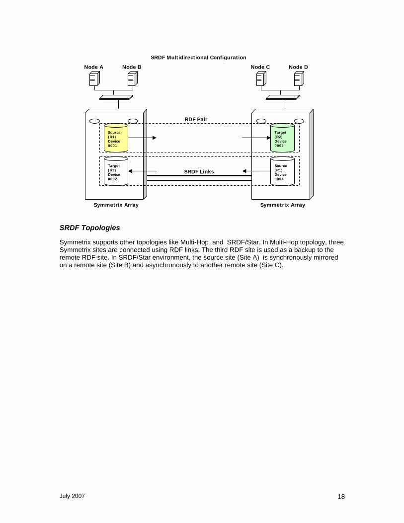
Node A Node B
Source (R1) Device 0001
Target (R2) Device 0002
Node C Node D
Target (R2) Device 0003
Source (R1) Device 0004
Symmetrix Array Symmetrix Array
RDF Pair
SRDF Links
SRDF Multidirectional Configuration
SRDF Topologies
Symmetrix supports other topologies like Multi-Hop and SRDF/Star. In Multi-Hop topology, three Symmetrix sites are connected using RDF links. The third RDF site is used as a backup to the remote RDF site. In SRDF/Star environment, the source site (Site A) is synchronously mirrored on a remote site (Site B) and asynchronously to another remote site (Site C).
July 2007 18

Node A Node B
Source (R1) Device 0001
Node C Node D
Target (R2) Device 0003
Symmetrix Array Site A
Symmetrix Array Site B
RDF Pair
Synchronous Links
SRDF STAR Environment
Symmetrix Array Site C
Target (R2) Device 0005
Asynchronous Links
SRDF Device Types and Groups
The individual Symmetrix devices are either assigned as a source(R1 device) or a target device (R2 device) to synchronize and maintain remote mirroring activities. If the source device fails, the data on the target device can be accessed by the local host. Once the source device is replaced, it can be resynchronized. An RDF pair consists of a source device (R1) and the corresponding target device (R2)
Source (R1) Device 0001
Target(R2) Device 0003
RDF Pair
An RDF device group is a user-defined group consisting of a set of RDF devices belonging to a single Symmetrix array. The RDF device group could be of REGULAR, RDF1(source) or
July 2007 19

RDF2(target) ) types and is defined during the time of the group creation. Each group macontain various device lists for standard, BCV, virtual (VDEV), and remote devices. By defaudevice cannot belong to more than one device group but you can modify the default behavior to allow the device to belong to multiple groups. Using device group, you can execute group commands applicable to all the devices in the group. For example, ‘symrdf –g RAC establiscommand initiates a full replication of all the devices in the RDF group RAC. All the data from the source devices are copied over the target devices and replication is established.
y lt, a
h –full’
SRDF provides capabilities to create composite, dynamic and consistency RDF groups. A p
ple
Disabled) state and based
SRDF Setup and Management YMCLI) can be used to configure and manage SRDF. The
To display all the Symmetrix array that are reachable through SRDF links
Source(R1) Device 0003
Source(R1) Device 0004
Source (R1) Device 0001
Source (R1) Device 0002
composite group can have multiple Symmetrix arrays and RDF groups. A consistency groupreserves the integrity and dependent write consistency of a database distributed across multiarrays. Consistency groups prevent dependent I/O from getting out of sync, thus ensuring the integrity and consistency of the remote data. By enabling consistency protection to a device group, if data cannot be copied from the R1 to R2 for a particular device then all the devices inthe group will be made Not Ready on the link to preserve target data consistency. This feature will help databases to be recovered safely at the target location.
The SRDF devices and links maintain a (Ready, Not Ready or Writeon the SRDF control operations the status of their state changes.
Symmetrix command line interface (Sfollowing examples describe some of the basic commands. For further information refer to the Symmetrix SRDF documentation.
symcfg list
Symmetrix Array
Source (R1) Device 0005
Source (R1) Device 0006
Source(R1) Device 0007
RDF Device Group1
RDF Device Group2
July 2007 20

To list the device group by name and type
symdg list
To display SRDF devices that are visible to the host
symrdf list pd
To view the SRDF information on all the devices in a device group
symrdf –g device_group query
July 2007 21

To create an RDF Device Group of type RDF1
symdg create device_group –type device_type
To add devices into an RDF Device Group
symld –g device_group add dev device_id
To create an SRDF pair
symrdf createpair –sid array_id –file devicefile –type rdf1 –rdfg grpnum –establish
Array_id is the local Symmetrix Array Id (Example: 000187400527)
The last four digits are sufficient in most cases. (Example: 0527)
The grpnum is the RDF (RA) group number. ‘symrdf list pd’ command displays the RDF Type and Group number. In the above example, the RDF group number is 11.
A devicefile contains device pairs as mentioned in the below format.
July 2007 22

0042 0024
004E 0030
004F 0031
0050 0032
0051 0033
0052 0034
To perform establish on RDF pairs
When a full/incremental establish is initiated, the target devices(R2) are write disabled and all the tracks on the target devices are refreshed by the corresponding R1 devices.
Source (R1) Device 0001
Target(R2) Device 0003
Source (R1) Device 0002
Target(R2) Device 0004
R2 devices data is refreshed from R1 devices
Write-DisabledWrite-Enabled
SRDF Links
ne is
symrdf –g device_group establish –full ( For a full establish )
symrdf –g device_group establish –full DEV001 ( For a full establish on one RDF pair)
symrdf –g device_group establish ( for an incremental establish )
symrdf –g device_group establish DEV001 DEV002 ( for an incremental establish on two RDF pairs)
Other SRDF Control Operations
Using SRDF control commands, the replication process can be halted and the target device data can be accessed for reading and writing. With a full restore command, the entire contents of the target devices are copied to the source devices.
July 2007 23

Source (R1) Device 0001
Source (R1) Device 0002
Target(R2) Device 0004
When a restore command is issued, R2 devices data is copied to R1 devices
Write-Disabled Write-Disabled
SRDF LinksTarget(R2) Device 0003
With a failover command, the source devices are write-disabled and the target devices are write-enabled. The target devices are available for write access. With a failback command, the R2 data changes are copied back to the R1 data and the roles are switched back. The source (R1) devices are write-enabled and the target (R2) devices are write-disabled.
Source (R1) Device 0001
Target(R2) Device 0003
Source (R1) Device 0002
Target(R2) Device 0004
When Failover command is issued on SRDF devices
Write-Disabled Write-Enabled
SRDF Links
July 2007 24

Conclusion
SFRAC using SRDF simplifies the organization’s ability to recover mission-critical applications. The recovery time is quicker and provides the ability to recover in a well-defined, highly-automated manner. Using Synchronous replication, the failovers can be tested switching the remote cluster as the primary cluster without loss of transactional data. Using VCS SRDF Agent, the direction of replication is reversed very easily.
July 2007 25