stock preparation part 1 – pulp treatment processes
TRANSCRIPT

STOCK PREPARATIONPART 1 – PULP TREATMENT
PROCESSES
Jean-Claude Roux
Laboratoire de Génie des Procédés PapetiersUMR 5518 au CNRS/INPG/CTP/EFPG
Ecole Française de Papeterie et des Industries GraphiquesBP 65 – 38402 Saint-Martin d’Hères Cedex – FRANCE
ABSTRACT
The re-pulping, refining and hot dispersing processes are con-sidered in this first part “Pulp Treatment Processes” of the reviewpaper about “Stock Preparation”, which focuses on the processengineering aspects of the unit operations used in the productionof virgin and recycled pulps. Chemical and physical-chemicalaspects are beyond the scope of this paper, as are pulp dilution,transport and storage.
The pulp treatment processes refer to the unit operations aim-ing at altering and/or upgrading the fibrous raw material andassociated solid materials and contraries (inks and various con-taminants). They include re-pulping or disintegration, refining orbeating, hot dispersing and mixing. Pulp disintegration has curi-ously never been of great interest to the paper science community,and hence remains an area of investigation where quite substan-tial benefits could be gained through reductions in energy con-sumption. Some new approaches will be presented that get roundthe difficult concept of pulp apparent viscosity, which is really anaspect of rheology. One of the main operations in stock prepar-ation is obviously pulp. While the effects of refining on fibres havebeen extensively studied in the past, its engineering parameters
12th Fundamental Research Symposium, Oxford, September 2001 19
Preferred citation: J-C. Roux. Pulp Treatment Processes. In The science of papermaking, Trans. of the XIIth Fund. Res. Symp. Oxford, 2001, (C.F. Baker, ed.), pp 19–80, FRC, Manchester, 2018. DOI: 10.15376/frc.2001.1.19.

have not. For example, we do not yet know how to extrapolaterefining results from the pilot to the industrial scale. It is evendifficult to compare the effects of conical and disc refiners on thesame pulp. It seems that only an integrated approach can improveour understanding of this process; one such will be proposed,building on fundamental engineering principles.
Then, the paper goes on to consider hot dispersion, an import-ant process step in the field of paper recycling and deinking, tocomplete the effects of pulping and/or refining in terms of inkdetachment, alteration of contaminants and fibre conformability.Hot dispersion is generally combined with bleaching because ofthe high temperature, consistency and mixing effect.
INTRODUCTION
Stock preparation, in the broad sense of producing a fibre suspension in asuitable form for the paper machine from the various fibre resources, includesthe manufacture of chemical pulps, high-yield pulps and non-wood pulps aswell as the recycling of recovered papers. The mechanical processes used inthese applications can be classified in two main groups, considered in the twoparts of this review:
• Pulp treatment processes: pulping, refining and hot dispersing.• Particle separation processes: screening, cleaning, flotation and washing.
Chemical processes and physical-chemical aspects are outside the scope ofthis paper, as are wood and water treatment, and pulp dilution, transport andstorage. The pulp treatment processes considered in this first part are ofconcern in the various sectors of stock preparation.
In chemical pulp mills, high consistency refining is normally used for theproduction of unbleached pulps for packaging applications. In the manu-facture of high-yield pulps, the second refining stage and the associatedscreening systems are key steps in achieving the necessary fibre developmentand shive removal.
The recent introduction of the Bivis extruder for processing non-woodfibres must be mentioned. Bivis extrusion is a mechanical pulping process,with a defibreing action lying between grinding and refining [1,2]. It alsofunctions as both a high temperature short time reactor and a washer sincechemicals can be added and dissolved material removed as the pulp movesalong the two extrusion screws [3,4]. The Bivis process is used in the manu-
20 Session 1: Fibres and their Preparation
J-C. Roux

facture of printing and packaging papers from wood [1–4] and annual plants[5,6].
Re-pulping recovered paper is clearly an important process in recycling.The mechanical action in pulping has to be optimised so as to ensureadequate defibreing of the re-pulped paper, while avoiding excessive sizereduction of the various contraries, which would reduce their removal insubsequent screening. In deinking, the process must also detach ink particlesfrom the fibres, without excessive ink fragmentation, which would reduceremoval in flotation. Hot dispersion is essential to detach residual inks forremoval in a second deinking step. In packaging recycling, it is used to dis-perse residual contraries, especially hot melt glues and flakes, to sizes belowthe visible limit. However, current trends are to replace hot dispersing by finescreening, since the process, by not removing contaminants but only disper-sing them, does not solve the problems of deposits on the paper machine.
Finally, refining is the key process in developing the strength properties ofrecycled papers, especially packaging grades, where it is usually performed onthe separated long fibre fraction. Refining is also important in manufacturingdeinking grades, especially in high quality graphic paper.
RE-PULPING/SLUSHING OPERATION
Technological description
Pulp disintegration is a three-way operation, consisting of agitation by bulkmotion, mixing of the slurry and dispersion by reduction of the solid particlesize. The objectives are to obtain a pumpable, homogeneous slurry and toseparate contaminants, ink particles and fibres [7]. The equipment useddepends mainly on the feeding process and on the furnish nature. In the caseof a non integrated mill, the fibrous raw material is received as bales of 90–95% air dry sheets, which are re-pulped into a slush as needed. In the case of apulp mill integrated with a paper mill, chemical, mechanical and/or recycledpulps may be pumped from storage chests in slush form (3–6%). In the caseof a recycled fibre furnish, the pulp must be cleaned and screened to removeany undesirable materials which could damage stock preparation equipment.Then, broke, common to all types of paper mills, must also be slushed forreuse and blended into the furnish [8].
Depending on the consistency, various different technologies exist to per-form pulp disintegration. This paper will not review all the technologicalsolutions available in the market; certain typical solutions will be given asillustrative examples.
Figure 1 illustrates a classical pulper used in the low consistency range. It
12th Fundamental Research Symposium, Oxford, September 2001 21
Stock Preparation Part 1 – Pulp Treatment Processes

consists of a tank with internal deflectors to promote efficient bulk motion, arotor equipped with blades to induce shocks on contact with the pulp, and aperforated bed-plate to remove large size contaminants.
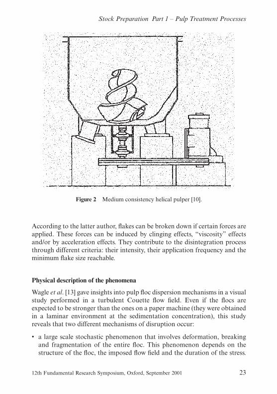
Figure 2 illustrates a pulper used where disintegration is performed in themedium consistency range. The main difference lies in the shape and thevolume of the rotor; the helical vanes induce a motion to direct the pulptowards the agitated region near the rotor. Paraskevas [11] estimates that apulper consumes from 5–15% of the total energy used in a paper mill. Despitethis significant proportion, pulp disintegration has never stimulated any greatinterest in the paper science community. Reasons for this probably include thereal difficulty of describing a three-way process dealing at the same time withagitation, mixing and dispersion of a pulp suspension; and the challenge ofmaking direct measurements in a pulper. It seems that the technical literaturevery often reflects qualitative descriptions of the phenomena that occur dur-ing disintegration, following the work of Paraskevas [11] and Holik [12].
Figure 1 Classical pulper for low-consistency range [9].
22 Session 1: Fibres and their Preparation
J-C. Roux
According to the latter author, flakes can be broken down if certain forces areapplied. These forces can be induced by clinging effects, “viscosity” effectsand/or by acceleration effects. They contribute to the disintegration processthrough different criteria: their intensity, their application frequency and theminimum flake size reachable.
Physical description of the phenomena
Wagle et al. [13] gave insights into pulp floc dispersion mechanisms in a visualstudy performed in a turbulent Couette flow field. Even if the flocs areexpected to be stronger than the ones on a paper machine (they were obtainedin a laminar environment at the sedimentation concentration), this studyreveals that two different mechanisms of disruption occur:
• a large scale stochastic phenomenon that involves deformation, breakingand fragmentation of the entire floc. This phenomenon depends on thestructure of the floc, the imposed flow field and the duration of the stress.
Figure 2 Medium consistency helical pulper [10].
12th Fundamental Research Symposium, Oxford, September 2001 23
Stock Preparation Part 1 – Pulp Treatment Processes
Whenever the net tensile strength applied to the floc exceeds a minimumyield value, then the floc disrupts with a high rate process.
• a local small-scale erosion phenomenon which requires lower stresses andoccurs over the entire surface of the floc.
These mechanisms can be linked in a first-order kinetic process to describefloc dispersion. This is of primary importance when one remembers that soliddispersion occurs simultaneously with agitation and mixing in the disintegra-tion process.
Kinetics of disintegration
Only recently, Bennington [14] quantitatively described the kinetics of dis-integration by considering the total area of the rotor in contact with the solidfibrous material. In this description, the interactions between fibres or flakesand rotor are responsible for pulp disintegration. If F stands for the flakecontent, the authors obtained:
dF
dt= k.F (1)
where k is the first-order rate constant (negative value). Rewriting the previ-ous equation as:
dF
dCR
= k′.F (2)
where CR is the fibre-rotor contact area given by the product of the volu-metric concentration Cv and the area swept out by the rotor:
CR = Cv.B.N.G.t (3)
where N is the rotation speed of the rotor, B the number of rotor vanes, and Gthe surface area a single vane sweeps out during one revolution and t is thetime. This model was validated for a single helical rotor, using varying rotorspeeds and suspension consistencies and for three different furnishes. Figure3, where the flake content is plotted versus the fibre-rotor contact area, illus-trates this. All the consistencies are located on the same master curve for agiven fibrous raw material.
The experimental results were in accordance with the model obtained bythe integration of the differential equation (2):
24 Session 1: Fibres and their Preparation
J-C. Roux

ln(F) = k′.CR (4)
In order to improve the knowledge and to generalise this approach takinginto account all fibrous raw materials, the authors expected that the constantk′ followed the Arrhenius equation used to describe chemical kinetics:
k′= k′0, exp�−TM
K.FR� (5)
where the material strength given by the wet tensile strength TM was com-pared to the mechanical applied force FR that can be evaluated using the netpower Pn:
Figure 3 Flake content versus the fibre-rotor contact area CR [14].
12th Fundamental Research Symposium, Oxford, September 2001 25
Stock Preparation Part 1 – Pulp Treatment Processes
FR =pn
π.Dm.N.B.Hc
(6)
where Dm is the mean diameter of the rotor calculated by the mathematicalaverage in the z-direction and Hc is the height of impeller in contact withsuspension. With the help of both coefficients k′0 and K, it is possible tosuccessfully model the disintegration kinetics.
This approach is very interesting but concerns only the contact between thesolid fibrous material and the rotor. It does not consider the disintegrationeffects that may occur from the fibre-fibre friction increasing with the massconsistency. Other attempts were investigated by Amaral et al. [15], Fabry etal. [16,17].
First attempt
The kinetics of the disintegration process can be assessed, for example, bycounting the number of flakes per mass N of dry material, on sheet samplesmade with pulp at varying times during the operation. If the pulp is toostrong to be disintegrated (wet strength materials), a number of indestructibleflakes, N ∞, remains. So, one assumes that the number of flakes that are dis-integrated per second is proportional to the remaining flakes that can bepotentially processed and to the net power dissipated per volume of pulpsuspension:
dN(t) = − b.[N(t) − N ∞ ] .Φs.dt (7)
where N(t) is the number of counted flakes per mass at time t and Φs is the netpower consumed per volume. This last differential equation may be integratedin a general sense and becomes:
N(t) − N∞ = (N0 − N∞).exp( −b. � i
0Φs(t′).dt′) (8)
The integral term is a key-factor in understanding the disintegration pro-cess; it defines the cumulative energy consumed per volume of pulp suspen-sion. It is easier to consider that the net power per volume of pulp suspensionis a constant value even if this assumption is not entirely true at the beginningof the process, where fluctuations have high amplitude (30% reported byBennington and Fabry). With this simplified assumption, one obtains a first-order kinetic law compatible with the previous analysis:
N(t) − N∞ = (N0 − N∞).exp(− b.Φs.t) (9)
26 Session 1: Fibres and their Preparation
J-C. Roux

where the product b.Φs can be identified as the first-order rate constant k.This experimental law is validated for bleached Kraft eucalyptus and soft-wood pulps in a laboratory pulper where the volume is 4.5 dm3, and fordifferent times of water impregnation (0.5 h and 1 h), in the low consistencyrange (between 3% to 4.5%).
Table 1 illustrates the results obtained in these conditions.
Second attempt
Let us consider that the process kinetic follows a law of evolution writtenwith the flake content F instead of the number of flakes per mass N:
dF(t) = − k.(F − F∞).dt (10)
and suppose that the first-order kinetic constant k results from the product ofa sensitivity term (α) by an average shearing stress in the bulk suspension (τ):
k = α.τ (11)
If one assumes that the net power dissipated per unit volume can be attrib-uted to the dissipation caused by an equivalent fluid, Rayleigh’s law can beapplied:
Φs =(τ)2
μ(12)
where μ is a so-called apparent viscosity in Pa.s. Some difficulties may arisesince this concept is not very well known in pulp suspension rheology and
Table 1 Determination of constants for the data of Amaral et al. [15].
Fibrous Mass0.5 h 1 h
rawmaterial
consistencyx %
Φ
10 5J.m−3.s−1
b10−8.J −1.m3
k10−3s−1
Φ
10 5J.m−3.s−1
b10−8 J−1.m3
k10−3s−1
Eucalyptus 3.0 1.08 8.98 9.70 1.06 9.89 10.53.5 1.20 5.18 6.22 1.10 8.76 9.644.0 1.11 3.11 3.45 1.09 4.70 5.124.5 1.14 6.61 7.54 1.13 4.14 4.65
Softwood pine 4.0 1.34 10.4 14.0 1.35 6.28 8.464.5 1.47 5.49 8.07 1.42 6.45 9.16
12th Fundamental Research Symposium, Oxford, September 2001 27
Stock Preparation Part 1 – Pulp Treatment Processes

furthermore has not yet achieved wide acceptance in the scientific com-munity. It seems desirable to consider this term as a shear-factor thatincorporates all the friction forces (even the friction solid-solid forces) in aviscous form [16,17]. Fabry et al. demonstrated that this shear-factor is astrongly increasing function of the mass consistency (denoted x), so it may bewritten for the bleached softwood and hardwood Kraft pulps at consistenciesbelow 10% as:
μ = μw.exp(β.x) (13)
where μw is the dynamic viscosity of water.Putting all the equations together, the first-order rate constant k becomes:
k = α.[μw.Φs.exp(β.x)]0.50 (14)
The sensitivity constant α is then supposed to be a decreasing function ofthe mass consistency x. The previous expression suggests looking for anexponential solution, so an assumption is made accordingly:
α = α0.exp(− λ.x) (15)
Whenever a disintegration trial is performed on a given pulper, with a givenrotor, known fibrous materials and running consistencies, the first-order rateconstant can be evaluated from flake measurements and the net power con-sumed per volume is also an information available.
k = α0.[μw.Φs]0.50.exp(σ.x) (16)
where:
σ =β2
− λ (17)
When varying the consistency for different trials, equation (16) can berewritten in order to determine both numerical values of α0 and σ from a plotof the first right-term versus the mass consistency:
ln{k.[μw.Φs]−0.50} = ln(α0) + σ.x (18)
This methodology was successfully applied to integrate the already
28 Session 1: Fibres and their Preparation
J-C. Roux

published data of Amaral et al. [15], Merrett [18] and Savolainen et al. [19].The results are given in the following Tables (2–4).
Table 2 Determination of the first-order kinetic constant k from Amaral et al. [15].
Fibrousraw
Massconsistency
0.5 h 1 h
material x % k 10−3s−1 ln[k.(μw.ΦS)−0.5] k 10−3s−1 ln[k.(μw.ΦS)−0.5]
Eucalyptus 3.0 9.70 −6.98 10.5 −6.893.5 6.22 −7.47 9.64 −6.994.0 3.45 −8.02 5.12 −7.624.5 7.54 n.d. 4.65 −7.73
Softwood 4.0 14.0 −6.72 8.46 n.d.pine 4.5 8.07 −7.31 9.16 −7.17
Table 3 Determination of the first-order kinetic constant k from Merrett [18].
Fibrous rawmaterial
Temp.°C pH
Masscons. %
Φs
104 J.m−3.s−1k10−3 s−1
I∞
% ln[k.(μw.ΦS)−0.5]
Mixed of 47 10.1 4.8 1.96 ± 0.08 3.03 0.4 −7.29waste 48 10.1 12.7 3.33 ± 0.47 5.97 0.4 −6.87papers 60 10.2 14.4 3.24 ± 0.33 6.93 0.4 −6.71
Wet 73 11.2 5.5 2.07 ± 0.16 0.42 n.d. −9.29strength 74 10.6 14.0 3.22 ± 0.04 0.80 n.d. −8.87boards 79 11.8 14.0 3.15 ± 0.09 1.10 n.d. −8.54
Table 4 Determination of the first-order kinetic constant k from Savolainen et al.[19].
Fibrous rawmaterial
Massconsistency %
Φs
104 J.m−3.s−1k10−3 s−1 ln[k.(μw.ΦS)−0.5]
Box 3.5 2.0 1.04 −8.37corrugated 7.0 1.31 −8.14papers 8.5 1.57 −7.95
Calendered 3.5 2.0 12.3 −5.90papers 7.0 12.4 −5.89
10 14.3 −5.75
12th Fundamental Research Symposium, Oxford, September 2001 29
Stock Preparation Part 1 – Pulp Treatment Processes

The trials from Amaral et al. were performed in the low consistency rangeand negative values were obtained for σ. It reveals that the increase in theshear-factor with consistency, compared with the greatest possible decreaseof the pulp sensitivity to disintegration, is not sufficient to increase the first-order constant rate of the process. As a consequence, this first-order rateconstant k must always be a decreasing function of the mass consistency.
On the contrary, whenever trials have been performed in the medium con-sistency range, the σ coefficient has been found to be positive. This supportsthe well-established use of medium range consistency for pulp disintegration.Accounting for all the data available coming from different authors, themodel proposed is as satisfactory as possible, as shown in Figure 4 whichcompares the kinetic constant evaluated from direct measurements and calcu-lated according to the formula (16).
Figure 4 Comparison between the calculated and evaluated values of the kineticconstant for all the authors analysed.
Table 5 Evaluation of the constants for kinetic modelling of pulp disintegration.
Authors Fibrous raw material α0 (Pa.s)−1 1/α0 Pa.s σ
Amaral et al. Eucalyptus pulp 7.01 × 10⁻³ 143 −67Softwood pine pulp 8.08 × 10⁻² 12.4 −105
Merrett Mixed of waste papers 5.16 × 10⁻⁴ 1940 5.76Wet strength boards 6.31 × 10⁻⁵ 15,900 6.92
Savolainen et al. Box corrugated papers 1.74 × 10⁻⁴ 5740 7.95Calendered papers 2.49 × 10⁻³ 403 2.26
30 Session 1: Fibres and their Preparation
J-C. Roux
If we compare the varying coefficients for all the pulps investigated, theterm α0
−1 expresses an initial resistance of the fibrous raw material to disinte-gration. In Table 5, a classification of the propensity of varying pulps to bedisintegrated is obtained: starting with the least resistance, we find: softwoodKraft pine pulps: then eucalyptus pulps: calendered papers: mixed wastepapers: corrugated box papers; and, at last, wet strength boards.
Pulping: a key-operation for deinking [20]
In [14], Bennington et al. developed a model for the action of a helical pulperto study the effect of mechanical action on waste paper defibreing and inkdetachment. Their model postulates that fibre/rotor interactions are respon-sible for defibreing. Knowledge of the area swept out by the rotor is necessaryin this model, though its determination depends on measuring the height ofthe suspension in the pulper. Besides, with the introduction of chemicals, theunderlying concept does not account for the flow modification that mayoccur. Previous work showed that differences of fragmentation and residualink cannot be explained solely by physical-chemical phenomena [21]. Thehypothesis of a mechanical action was then advanced. A rheological methodwas then used to estimate the shear-factor (generalisation of the viscosity) ina planetary mixer running as a pulper. This method was applied to 100%ONP (old newsprint papers) pulping to verify if mechanical action is correl-ated to ink fragmentation and ink removal by flotation.
Figure 5 illustrates the planetary mixer used. Whereas it is not yet used inthe pulp and paper industry, it has found application as a pulper on a labora-tory scale. With this type of mixer, defibreing is based on the application ofheavy impact forces uniformly distributed between the impeller and the tankwall. The continuous change of impeller position (planetary motion) meansthat the motion of the pulp suspension differs from that in a classical pulper(see Figures 1 and 2). But this allows disintegration of 100% ONP at a con-sistency around 20% whereas a consistency of 9% is the limit for this furnishin a helical pulper. The high consistency increases friction between the fibresin the overall volume of the tank, not just around the impeller.
Rheological characterisation
The planetary mixer used in this study is a Hobart mixer. It has a volume of10 dm3 and the rotor speed can vary from 50 to 155 rpm. According toMetzner and Otto [22], the power required to rotate an impeller (with arotation velocity N ) in a mixing vessel can be expressed as a function of fluidproperties (ρ density, μ dynamic viscosity) and of vessel geometry (d diameter
12th Fundamental Research Symposium, Oxford, September 2001 31
Stock Preparation Part 1 – Pulp Treatment Processes

of the rotor). The important ratios are the power number Np first and theReynolds number Re:
Pn
ρ.N 3.d 5= f �ρ.N.d 2
μ, vessel – geometry – factor�
This analysis can be used to determine the characteristic curve of theimpeller with Newtonian fluids (mixtures of water and glycerol solutions)where the viscosity is independent of the shear rate (and thus of the rotorspeed). An example of this characteristic is represented in Figure 6 for themixer with a hook impeller.
• At low Reynolds number below 200, the characteristic curve can beexpressed by Np = K/Re. The value of K depends on each type of impel-ler: 183 for the hook impeller and 371 for the flat beater. In the laminararea, it is possible to define an apparent viscosity accordingly:
μapp =Pn
K.d 3.N 2(19)
Figure 5 Hobart planetary mixer with flat beater on the left and hook impeller onthe right.
32 Session 1: Fibres and their Preparation
J-C. Roux

• At high Reynolds number, the power number is independent of the Rey-nolds number.
A pulp is a non homogeneous and compressible medium, and, as the par-ticles (fibres, flocs) can be deformed by shear, it is difficult and unrealistic toascribe an apparent viscosity to a pulp suspension. This is especially truewhen the consistency is so high that its motion cannot be compared with thatof a fluid. For these reasons, we prefer to generalise the apparent viscosity ina shear factor named λ to distinguish from the apparent viscosity. In thisapproach, we posit that the total amount of energy consumed is supposed tobe consumed by friction of any kind. This overall friction is analogous to theliquid friction of an equivalent fluid which consumes the same power at thesame rotor speed.
The results obtained with the planetary Hobart mixer are illustrated inFigure 7. The shear factor is an increasing function of the consistency. For agiven consistency, the flat beater leads to a higher value of λ than the hookimpeller. This may be due to higher contact area with the fibre and hencewould be consistent with Bennington et al. [14] analysis. λ is a quantificationof the overall friction phenomena that occur in the mixer: higher frictionhelps defibreing.
Figure 6 Characteristic curve of the Hobart mixer with a hook impeller.
12th Fundamental Research Symposium, Oxford, September 2001 33
Stock Preparation Part 1 – Pulp Treatment Processes

Figure 7 Shear factor as a function of consistency and impeller geometry.
Figure 8 Defibreing of 100% ONP versus pulping time.
34 Session 1: Fibres and their Preparation
J-C. Roux

The defibreing degree was assessed by the flake content measured in aSomerville apparatus with slots of 8/100 mm width. The flake content isshown in Figure 8 versus pulping times, where it is seen that the flat beaterleads to an increase in the defibreing kinetics. The effect of consistency is wellknown and has already been reported [11,12].
A master curve can be obtained if the flake content is plotted versus theenergy consumption. This result is remarkable and reveals that this curve isindependent of both the impeller type and the pulping consistency. Thus, thedefibreing level of the pulp can be known if the energy consumption is meas-ured: the higher the energy, the lower the flake content. This is illustrated inFigure 9.
Papermakers using recycled fibre are mainly concerned with the problem ofthe ink fragmentation that may occur in the defibreing stages. Brightnessmeasurements were performed on the entire pulp and reveal that anothermaster curve is obtained when plotting this brightness versus the pulpingenergy consumption. This curve, in Figure 10, is independent of the impellertype and of the consistency.
In order to demonstrate that the main physical quantity to assess defibre-ing is the energy consumption, Figure 11 illustrates the speck contaminationversus the pulping energy consumption. Once again, a master curve isobtained whatever the impeller type and the consistency. The higher the
Figure 9 Defibreing versus pulping energy consumption.
12th Fundamental Research Symposium, Oxford, September 2001 35
Stock Preparation Part 1 – Pulp Treatment Processes

Figure 10 Ink fragmentation versus pulping energy consumption.
Figure 11 Speck contamination versus pulping energy consumption.
36 Session 1: Fibres and their Preparation
J-C. Roux

pulping energy consumption, the lower the speck contamination. The helicalpulper is given as comparison.
In high consistency disintegration (8–20%), the energy consumed is givenby the following expression:
E(t) = K.λ.N 2.d 3.t
This last expression gives prominence to two influences:
• a geometrical term related to the area swept out by the rotor in contactwith fibre suspension in the effective shearing zone. These parameters (K,d ) can be adjusted by the machinery suppliers;
• a rheological term, through the shear factor λ, related to an average shearduring pulping. Adding chemicals such as soda may influence the shearfactor and hence the resistance of the flakes to breaking down.
In order to obtain a good pulp quality in the disintegration stage, sufficientenergy must be consumed, as was proved for the defibreing effects with theSomerville index and for speck contamination. However, overall pulp bright-ness shows an opposite tendency with increasing energy consumption, due toink fragmentation. A solution may be obtained by reducing the pulping timeand increasing the shear factor. In that case, the expected process gains are asfollows: better pulp quality, higher productivity, energy saving and lowercontaminant fragmentation.
REFINING/BEATING PROCESS
Technological description of the refining operation
Several excellent review papers [23,24,25] have already been devoted to therefining/beating process: a good example being that at the Ninth Symposiumin Cambridge. The purpose of this new one is to identify some of the keyquantities that play a role in the operation through a global, physical descrip-tion of the phenomena.
Before recalling some generalities (more on the process itself than on itswell known effects on fibres), a close look at Figure 12 shows that there is arather wide choice in the technology of refining machines available on themarket, from the old Hollander beater to the multi-disc. However, extrapolat-ing refining results from pilot to industrial scale remains a key motive foraddressing the operation of refining.
Fibres are refined or beaten in refining machines in the presence of waterunder both pressure and shearing action between surfaces in relative motion.
12th Fundamental Research Symposium, Oxford, September 2001 37
Stock Preparation Part 1 – Pulp Treatment Processes

These surfaces may be fitted with bars on the bed-plate (or the stator) and therotor, though these are not necessary to get refining action. However, mostindustrial refiners do have bars. Even in low-consistency refining (2–6%), thefibres do not remain single: they form flocs; and, as maximum shear rates maybe very intense (in the order of magnitude of 5 to 6), these flocs re-disperseand re-form continuously.
A key quantity in all these machines is the gap clearance, the distancebetween the refining surfaces. This gap clearance must be sufficiently small tosupport the load. With water alone, it is impossible to form such a gap. It isonly possible with pulp suspensions due to their load-carrying capacity. Fromthese statements, it can be seen that the concepts of yield gap clearance (forrefining effects to occur) and of loading force must be included in any fulldescription of the refining/beating process. What can be learnt from the pulpflow in a disc-refiner for example? In the past, Fox et al. [26] investigated anexperimental refiner at 1.1% consistency. Extrapolating their observationsand analysis to low-consistency, the fibre-flocs are seen to be stapled againstthe leading edge of the stator bars, which are covered to between 50–70% oftheir width. However, it seems that the physics of the flow is very complicatedand that understanding it fully is not easy. Centrifugal flows occur in therotor grooves: centripetal reverse flows take place in the stator grooves, andintermixing flows between the two.
Many authors, e.g. Steenberg [27], have described the phenomena involvedin the mechanics of refining; and it is essential to use their analysis as astarting point for any attempt at further quantification. Thus, in any refiningmachine, when the gap clearance is sufficiently small, the fibre-flocs consoli-date when trapped between approaching tackle elements (relative motion andconsolidation). Then when the surfaces overlap totally, a strong mechanicalpressure is applied. Plastic deformation may occur at this stage. The shearingaction is also intense since the tackle elements are moving and some
Figure 12 Different typical refining machines.
38 Session 1: Fibres and their Preparation
J-C. Roux

fibre-flocs may be ruptured also. Then follows a relaxation of the mechanicalpressure when water may be absorbed into the ruptured fibrils and fibresbefore turbulent agitation re-disperses the remnants into the general massflow.
When it is said that the effects on fibres/flocs are better known, it does notmean that the probability of the occurrence of each effect is known [24].According to Giertz [28], their probability distribution should follow adecreasing exponential function of the force intensity. As the intensity of therefining force increases, the following events are supposed to occur on theparticles, with decreasing probability: elastic and/or visco-elastic deformationof fibres together with a frictional dissipation in water: intra-fibre H-bondbreakage: unravelling of the cell wall: dislocations and delaminations; andfinally, cutting and crushing of fibres. However, what are these forces involvedin the process of refining? Can we explain the concept of refining intensity interms of some realistic physical background?
In order to provide at least partial answers to these fundamental questions,we begin by studying the decomposition of normal forces or axial forces insingle-disc refiners, with the help of a force balance, written for both largeand narrow gap conditions [29]. Important results arise from this quantifica-tion of the process that agree with the findings of previous authors (e.g.Banks [30]). This leads to the concept of the shear-factor, already applied tocharacterize the disintegration process, and the purpose of this section deal-ing with beating is to exemplify its use in understanding refining. But beforereaching this goal, the beating process needs to be more precisely defined interms of engineering. Since several entire papers have pointed out the need tore-think the fundamentals of the refining process, we are proposing a newapproach here. The shear factor is introduced to provide a physical under-standing of the effective normal and tangential forces. These results are thencompared to the engineering equation from Dalzell [31] and to the hydro-dynamic modelling of Radoslavova et al. [32]. Interesting results are given interms of a pressing process for disc refiners with the help of the shear factor[33]. Then, the refining kinetics are detailed. The last section ends up bygiving some physical backgrounds to better define the classical refiningintensity.
Physical description
Decomposition of normal forces in disc refiners
The demonstration can be performed on a single-disc refiner. When a pulpsuspension flows through the small gap clearance between the refiner plates,tangential and normal forces are exerted on the plates themselves.
12th Fundamental Research Symposium, Oxford, September 2001 39
Stock Preparation Part 1 – Pulp Treatment Processes

Leider and Nissan [34] described the mechanical behavior of a pulp sus-pension in a refiner as a solid or a liquid body, but it is more desirable to dealwith the suspension as a two-phase material. An interesting starting point forthe calculation of the elementary friction force over a small annulus betweenthe radius ρ and ρ + dρ is:
dFf (ρ,t) = f (t).Pm(t).ξ.2πρ.dρ (20)
where f (t) stands for an overall friction coefficient for the fibre suspension/metal bar combination. Pm(t) is the average mechanical pressure [35] exertedon the compressed fibrous pads in the inter-crossing areas of the bars of therefiner. ξ is the ratio of this inter-crossing area versus the global area, givenby:
ξ =asar
(as + bs)(ar + br)(21)
where a and b are respectively the width of the bars and grooves, and thesubscripts s, r stand for the stator and rotor disc respectively. In the samemanner, the elementary normal force is given by the following:
dRn(ρ,t) = Pm(t).ξ.2πρ.dρ (22)
This force is exerted on the compressed fibre pads in all the confined zones(the intercrossing areas) in the gap clearance. An interesting and importantpoint must be made that applies in Equations (20) and (22), under both refin-ing and no-refining conditions. In order to find the overall force in the inter-crossing areas, their integration must be performed over the annulus betweenthe internal and external radii, ρi and ρe. Both the friction coefficient f(t) andthe average mechanical pressure Pm(t) are supposed to be uniform over theannulus to the first order. The integration of (20) and (22) leads to:
Ff (t) = f (t).Pm(t).ξ.π(ρe2 − ρi
2) (23)
and thus to the determination of the normal reaction force:
Rn(t) = Pm(t).ξ.π(ρe2 − ρi
2) =Ff (t)
f (t)(24)
If the gap clearance is large enough that no refining effect occurs on thepulp suspension (i.e. on the fibres), then equation (24) can be written:
40 Session 1: Fibres and their Preparation
J-C. Roux
Rn0 = Pm
0.ξ.π(ρe2 − ρi
2) (25)
with the superscript 0 meaning no refining effect at all. It is likely that Pm0 is a
hydraulic pressure so it will be defined as Ph. Hence, any measurement of Rn0,
the reference normal reaction force, allows Ph to be determined. Based upon aseries of trials, it was found that this pressure also applies in the grooves whenthe gap clearance is either small or large [36]. In either refining or no-refiningsituations, it is thus assumed that the pressure Ph is maintained in the grooveswhatever the magnitude of the gap clearance, and that it is not a time-dependant quantity. Consequently, the normal reaction force Rn
0 is invariantand not affected by the state of refining of the pulp:
�Rn0
�t= 0 (26)
However, on the contrary the equivalent frictional force Ff0 may be affected
by the refining state of the pulp according to:
Ff0(t) = f (t).Rn
0 (27)
The previous remarks are of primary importance when it is desired todefine the effective part of the normal reaction [37] and of the frictional force,since one reference may change with the time t:
�Fneff(t) = Rn(t) − Rn
0
Ffeff(t) = Ff (t) − Ff
0(t) (28)
Taking into account Equations (24) and (25), under kinetic conditions thefollowing expressions are obtained:
�Fneff(t) = (Pm(t) − Ph).ξ.π(ρe
2 − ρi2)
Ffeff (t) = f (t).Fn
eff(t) (29)
Until now the only forces considered arise in the inter-crossing areas ofbars. But any measurement of the normal compression force (or axial force)Fn(t) has two contributions:
• the normal reaction force Rn(t) in the inter-crossing area, and• the additional force Ph.(1 − ξ).π�ρe
2 − ρi2� in the complementary area.
Under refining conditions, this is written as follows:
12th Fundamental Research Symposium, Oxford, September 2001 41
Stock Preparation Part 1 – Pulp Treatment Processes

Fn(t) = Rn(t) + Ph.(1 − ξ).π(ρe2 − ρi
2) (30)
Under no-refining conditions, in the same manner:
Fn0 = Rn
0 + Ph.(1 − ξ).π�ρe2 − ρi
2� (31)
As a consequence, the effective normal force is given by the expression:
Fneff(t) = Fn(t) − Fn
0 (32)
Another way to write this is first to consider decomposing the acting nor-mal force into two parts: one constant, and one varying with time:
Fn(t) = Fn0 + Fn
eff(t) (33)
From the previous analysis and with the help of the measurement of Fn0 in
no-refining conditions, the hydraulic pressure Ph can be determined:
Ph =Fn
0
π(ρe2 − ρi
2)(34)
In the following paragraph, the formulae derived so far are applied to therefining of pulp suspensions. At this point, it is desirable to summarise theforces identified and how they can be measured.
From the measurement of the axial force with a strain gauge device, thebalance of forces allows the determination of the normal force:
Fn = Fjc + Fhs − Fhe (35)
Figure 13 Single-disc refiner.
42 Session 1: Fibres and their Preparation
J-C. Roux

Derivation of the net power
Different types of power can be defined in the refining process and it ispossible to simply derive the net power from the previous analysis. The fol-lowing demonstration of this derivation allows us to confirm the Banks for-mula, obtained in the early sixties [29]. The friction power consumed in arefiner can be determined by integration over the annulus of:
dPf (ρ,t) = dFf (ρ,t).2πρN (36)
This then leads to:
Pf (t) = f (t).Pm(t).ξ.4π2(ρe
3 − ρi3)
3.N (37)
In the case of large gap clearance, the average mechanical pressure revertsto Ph already defined and explained:
Pf0(t) = f (t).Ph.ξ.
4π2(ρε3 − ρi
3)
3.N (38)
It seems reasonable to admit that the net power may be calculated by thedifference between the two previous powers:
Peff = Pf (t) − Pf0(t) (39)
Peff is written instead of Peff(t) to take account of the fact that a controlsystem often imposes a constant refining power equal to a predefined set-point value. Another detailed expression of the net power is given by:
Peff = f (t).(Pm(t) − Ph).ξ.4π2(ρe
3 − ρi3)
3.N (40)
If the relative mechanical pressure is replaced according to the effectiveforce, then Peff becomes:
Peff = f (t).Fneff(t).2π.
2ρe(1 − k3)
3(1 − k2).N (41)
with an effective radius ρ calculated from the ratio k of the internal to theexternal radius:
12th Fundamental Research Symposium, Oxford, September 2001 43
Stock Preparation Part 1 – Pulp Treatment Processes
ρ =2ρe(1 − k3)
3(1 − k2)(42)
To summarize at this point, the measurements of both the normal com-pression force in loading Fn(t) and no-loading Fn
0 conditions allow the aver-age mechanical pressure Pm(t) and the average hydraulic pressure Ph to bedetermined according to:
Fn0 = Ph.π(ρe
2 − ρi2) (43)
and:
Fn(t) = [Ph + ξ.(Pm(t) − Ph)].π(ρe2 − ρi
2) (44)
Then, from Equation (41), the friction coefficient can be obtained:
f (t) =3.Peff
(Pm(t) − Ph).ξ.4π2ρe3(1 − k3).N
(45)
It is remarkable that Equation (41) gives legitimacy to the Banks formulaempirically derived in the early sixties, though the author did not preciselydefine either the friction coefficient or the axial force acting on the shaft of adisc refiner. The previous derivations clarify the equation and give these def-initions without any ambiguity.
The formulation between the net power and the shear factor
Previous published papers demonstrated that the shear factor Λ can be usedto describe the flow of a pulp suspension in small shear gaps. Hence one pointof departure could be to consider the pulp suspension as a homogeneousequivalent fluid, as was done by Leider and Nissan [34]. But it is more fruitfulto generalize the pulp apparent viscosity μα by the shear factor Λ, keeping thecomplex reality of both the pulp suspension and the shear field in the gapclearance. The shear factor incorporates the geometrical parameters inaddition to the fluid/suspension properties. In this case, the shear stress at thewall is given in terms of shear rate at the wall:
τw(ρ,t) = Λ(ρ,t).γw(ρ,t) (46)
where the shear rate can be expressed:
44 Session 1: Fibres and their Preparation
J-C. Roux

γw(ρ,t) =2πρN
e(t)(47)
e(t) stands for the mean gap clearance over the annulus. If the effectiveelementary frictional force is determined, one can obtain:
dFfeff(ρ,t)= Λ(ρ,t).ξ
4π2ρ2N
e(t).dρ (48)
A close examination of Equation (20) reveals that the shear factor Λ(ρ,t) isinversely proportional to the radius ρ and the rotation speed N:
Λ(ρ,t) =C1(t)
2πρN(49)
In order to obtain an overall quantity to describe the shear behavior of apulp fibrous suspension in disc refiners, the mean value of the shear factor Λis calculated:
Λ(t) =1
ρe(1 − k)�
k.ρe
ρe
Λ(ρ,t).dρ (50)
Then, the integration of the effective elementary frictional force leads suc-cessively to:
Ffeff(t) =
C1(t)
e(t).ξ.πρe
2(1 − k2) (51)
thence to the following equation with the mean shear factor Λ:
Ffeff(t) =
Λ(t)
e(t).ξ.
2π2ρe3(1 − k)(1 − k2)
ln(1/k).N (52)
If a refining trial is performed keeping constant the net power, Peff, com-bining Equations (29), (41) and (42) with Equation (52) gives:
Λ(t)
e(t).ξ.
2π2ρe3(1 − k)(1 − k2)
ln(1/k).N =
Peff
2πρ .N(53)
This demonstrates that the mean shear factor Λ(t) varies in the same way as
12th Fundamental Research Symposium, Oxford, September 2001 45
Stock Preparation Part 1 – Pulp Treatment Processes

the mean gap clearance e(t). As one of the objectives is to find the expressionof the normal reaction force exerted on the fibrous pads, one can derive itfrom (29) and (52):
Fneff(t) = �Λ(t)
e(t).ξ.
2π2ρe3(1 − k)(1 − k2)
ln(1/k).N�/f (t) (54)
Replacing ρ by its expression (28) in Equation (37), the net power Peff con-sumed during a refining trial can be derived:
Peff =8π3ρe
4(1 − k)(1 − k3)
3.ln(1/k).ξ.
N 2Λ(t)
e(t)(55)
In the past, many authors have studied the refining process and Dalzell [31]as cited by Ebeling [23] wrote an empirical equation in 1961 as follows:
Peff = k1
μ
(e)n.D.L.ξ.VP
2 (56)
where μ, D, L and VP stand for a coefficient of viscosity, an effective diameter,an effective length and the peripheral rotation speed. If the Dalzell equationis reworked and VP is replaced by 2πρeN, one can obtain:
Peff = k′1.4π2.D.L.ρe2.
N 2.μ
(e)n(57)
It is remarkable to have developed a fundamental theoretical description ofthe refining process involving the mean shear factor Λ. This equation clearlyprovides the foundation of the previous empirical work undertaken by Banks[30], Dalzell [31], Leider and Nissan [34]. Equations (55) and (57) are analogousand Dalzell remarked that his “coefficient of viscosity μ” is strongly affectedby the concentration: that is it increases with increasing concentration. Infact, μ is proportional to the mean shear factor Λ that generalizes the pulpapparent viscosity μa. The strong variation of μa with concentration has beenfound experimentally ([32] for example). If the net power and the mean gapclearance are recorded on a refiner, the mean shear factor Λ can be deter-mined by the following during the refining process:
Λ(t) =3.ln(1/k)
8π3(1 − k)(1 − k3).ξ.Peff.e(t)
ρe4.N 2
(58)
46 Session 1: Fibres and their Preparation
J-C. Roux

If the net power is eliminated from the previous equation using the frictioncoefficient expression, Equation (45), then a law similar to that of Petroff inlubrication theory may be obtained:
f (t) =2π.(1 − k)
ln(1/k).
Λ(t).N
(Pm(t) − Ph).
ρe
e(t)(59)
The two last ratios play an important role in the theory of lubrication ofbearings but in our case, all the key-parameters are related according to thisanalysis.
Experimental research
In order to understand the phenomena which occur in refining with the samefibrous raw material, a set of experimental trials was undertaken. For a longfibre pulp and various mixtures of this with a chemical-thermal-mechanicalpulp, the normal compression force and the corresponding gap clearancewere measured during refining trials performed in hydra-cycle mode on asingle-disc refiner with radii ρi = 66.5 mm and ρe = 152.5 mm. At constantpulp consistency c = 32 kg/m3, volumetric flow Q = 9.6 m3/h, rotation speed1550 rpm, cutting speed L· c = 11 km/s and with the net power consumedvarying from 6.3 to 11 kW, the effective specific energy was varied accordingto the time during a given trial:
Eeff (t) =Peff .t
ms
(60)
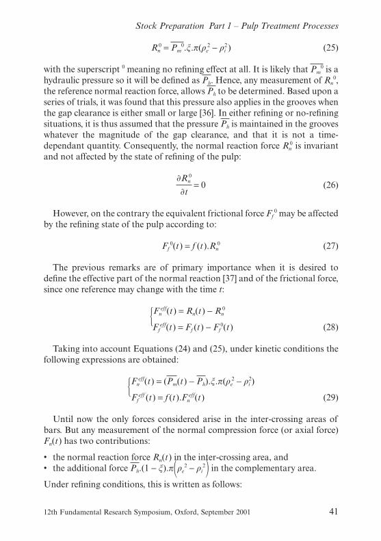
The corresponding specific edge load changed from 0.60 J/m to 1.00 J/mfor the long fibre and from 0.29 to 0.50 J/m for the whole pulp. In the differenttrials, the bar width, the groove width, the net power applied and the meancrossing angle of the bars were all used as variables to acquire the resultsrepresented in Figure 14.
The difference between the calculated and the measured values was alwaysfound to be below 6%: an acceptable discrepancy for industrial data obtainedon a pilot machine.
These results tend to validate the following model for the normal compres-sion force versus the gap clearance when refining this raw material:
Fn(t) =Fn
∞
1 + δ.e(t)(61)
The numerator expresses the maximum normal force of compression when
12th Fundamental Research Symposium, Oxford, September 2001 47
Stock Preparation Part 1 – Pulp Treatment Processes
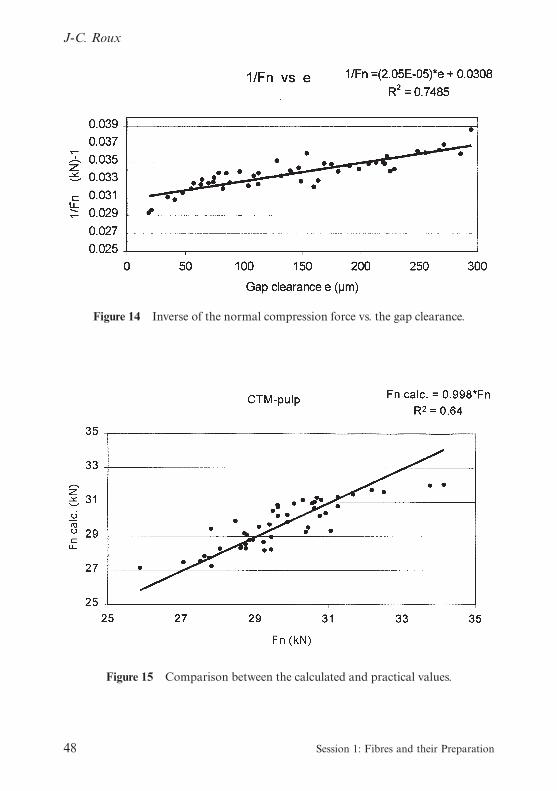
Figure 14 Inverse of the normal compression force vs. the gap clearance.
Figure 15 Comparison between the calculated and practical values.
48 Session 1: Fibres and their Preparation
J-C. Roux

the gap clearance is equal to zero. For example, on the CTM-pulp studied,this force was found in the range of 32.5 kN and δ was equal to 6.64 10−4
(μm−1). Combining the theoretical expectations (33) with the practical find-ings, the effective normal force may be written as:
Fneff(t) = (Fn
∞ − Fn0).
⎡⎢⎢⎢⎣
1 − � δ.Fn0
Fn∞ − Fn
0�.e(t)
1 + δ.e(t)
⎤⎥⎥⎥⎦
(62)
On the right-hand, the first term between parenthesis is the maximumeffective normal force that can be applied to the fibrous pads compressed inthe confined areas. This expression shows that a critical gap clearance isneeded to develop a positive and effective normal force. What does that meanin practice? If the gap clearance is above this critical value, then no appre-ciable fibre refining effect will occur. This critical value mainly depends ontwo mechanical parameters which are the limiting values of the normal com-pression force when the gap clearance is high enough (Fn
0) and when it isequal to zero (Fn
∞). The last parameter (δ) expresses the changes in com-pressibility of the fibrous pads in the intercrossing areas of bars during therefining process. This critical gap clearance is given by the following equa-tion deduced from the expression (62):
ec = �Fn∞
Fn0
− 1�.1δ (63)
Applied to the data for the CTM-pulp, a critical gap clearance of 285 μmwas found. From the knowledge of the effective normal force, the globalfriction coefficient may be easily derived. When refining in hydra-cycle mode,this coefficient changes with time according to the variations in the mechan-ical properties of the metal bar/fibre suspension combination. This subjecthas for a long time been a matter of speculation. Using expression (62), thischange can be calculated whenever the effective normal force is strictlypositive:
f (t) = fmin .
⎡⎢⎢⎢⎣
1 + δ.e(t)
1 −e(t)
ec
⎤⎥⎥⎥⎦
(64)
where the minimum value of the global friction coefficient is given by thefollowing expression:
12th Fundamental Research Symposium, Oxford, September 2001 49
Stock Preparation Part 1 – Pulp Treatment Processes

fmin =Ff
eff
Fn∞ − Fn
0(65)
During the refining process, the global friction coefficient decreases withthe gap clearance following Equation (64). The proposed model was validatedon the chemical-thermal-mechanical pulp with the previous data concerningthe whole pulp, as exemplified in Figure 16. However, some limitations arisefrom this model, the friction coefficient can not be reasonably defined whenwe are approaching the critical gap clearance since the effective normal forcereaches zero in that case.
Interpretation in terms of a pressing process
If the fibrous raw material is confined in the intercrossing areas of bars, theprocess may be interpreted in terms of consolidation (pressing). In the case ofa solid-liquid porous medium, the overpressure Pm − Ph can be written as asum of two pressures:
Ps: the structural pressure exerted on the solid phase (the fibres)ΔPh: the hydraulic pressure excess above its reference value Ph.
Study of the pressing process [35] identifies two specific behaviours: com-pression controlled and flow controlled modes. In compression controlledmode, the pressure is entirely supported by the solid phase (the fibres). This
Figure 16 Validation of the model for the global friction coefficient for a CTM-pulp.
50 Session 1: Fibres and their Preparation
J-C. Roux
occurs in refining when the gap clearance is decreasing and the fibrecutting effect reaches a maximum. Referring to the previous analysis, theeffective normal force is thus at a maximum while the friction coefficient isminimal. This is a regime of mainly solid/solid friction phenomena. Then,another regime takes over when the normal force and friction coefficient arequasi-constant. In that case, an analogy with flow controlled pressing can bemade. The overall mechanical pressure Pm is only in equilibrium with thehydraulic pressure Ph + ΔPh and the effects are mainly due to solid/liquidfriction. It is the perception of the author that the refining process may beunderstood by taking into account successively the two regimes: first thecompression controlled; then the flow controlled. For some fibrous rawmaterials, the first regime may be very short-lived so that the friction forcemaintains a constant value given by the overall friction coefficient for therefining process.
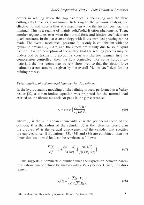
Determination of a Sommerfeld number for disc refiners
In the hydrodynamic modeling of the refining process performed in a Valleybeater [32] a dimensionless equation was proposed for the normal loadexerted on the fibrous networks or pads in the gap clearance:
rn = a + b. � μa.U.R
P0.(δh)2 � (66)
where: μa is the pulp apparent viscosity, U is the peripheral speed of thecylinder, R is the radius of the cylinder, P0 is the reference pressure inthe grooves, δh is the vertical displacement of the cylinder that specifiesthe gap clearance. If Equations (33), (34) and (54) are combined, then thedimensionless normal load can be rewritten as follows:
Fn(t)
Fn0
= 1 +ξ.(1 − k)
ln(1/k). � Λ(t).Vp
f (t).Ph.e(t) � (67)
This suggests a Sommerfeld number since the expression between paren-thesis above can be defined by analogy with a Valley beater. Hence, for a disc-refiner:
Sd(t) = � Λ(t).Vp
f (t).Ph.e(t) � (68)
12th Fundamental Research Symposium, Oxford, September 2001 51
Stock Preparation Part 1 – Pulp Treatment Processes

One remark arises from the previous paragraphs. Performing refining trialswith constant effective power keeps the ratio Λ(t)/e(t) constant, see Equation(53). This means that the Sommerfeld number is inversely proportional to thefriction coefficient. A simplified expression of the inverse of the friction coef-ficient may be written:
1
f (t)=
δ.Fn0
Ffeff
. (ec − e(t)) (69)
Taking into account Equation (52) for the effective friction force togetherwith Equation (69), a very simple formula is obtained in the case of a discrefiner which greatly simplifies the Sommerfeld number:
Fn(t)
Fn0
= 1 + δ.(ec − e(t)) (70)
This formulation is valid when the gap clearance is less than or equal tosome critical value at which refining effects begin to occur on the fibrous rawmaterial.
According to this research, the global set of data must follow the predictedevolution given by Equation (70). The results presented on Figure 17 are assatisfactory as possible with industrial data.
The delta value is known and, from the interpretations of the experimental
Figure 17 Variation of the normal compression force with gap clearance.
52 Session 1: Fibres and their Preparation
J-C. Roux

data, the critical gap clearance and the normal force in no-load conditionscan be quantified. Fn
0 = 27.2 kN and ec = 285 μm. Comparisons between bothanalysis lead to the following expression which linking the physical quantitiesto each other:
Fn0.(1 + δ.ec) = Fn
∞ (71)
Consequently, it is then possible to analyze the refining process in terms ofthe changes of the average mechanical pressure. Given this and rewritingEquation (44) leads to:
Pm(t) − Ph =Ph
ξ.δ. �ec − e(t)� (72)
In the limiting case where the gap clearance is chosen at zero, the maximalmechanical pressure over the hydraulic reference is equal to: (Ph/ξ).δ.ec or0.35 MPa.
Thus, both the effective normal force and the effective average mechanicalpressure vary linearly with the mean gap clearance, one of the key quantitiesin understanding the refining process.
Comparison with other mechanistic theories
Recently [38], an expression has been derived to predict the force acting on anideal floc undergoing compression between the passing bars of a refiner. Themodel equation is based upon three assumptions about flocs: they are spher-ical in shape with fibres evenly spaced in any cross-section; they cannot sup-port significant normal load until the majority of fibres are in contact; andthey display linear elastic behaviour under compression.
Figure 18 demonstrates the existence of two regimes:
• in the first, under uniaxial compression in the y-direction, the authorsassume the dominant action to be densification by decreasing pore size andincreasing fibre contact. The diameter of the ideal floc changes from L0 toγ .L0
• in the second, at some degree of compression, the number of fibres incontact is such that further compression of the floc requires significantforce to reduce the inter-fibre spacing. For wood fibres with hollow lumens,additional force is required to collapse the individual fibres themselves andto squeeze water out of the cell wall.
At the end of the first regime, the maximum floc size is:
12th Fundamental Research Symposium, Oxford, September 2001 53
Stock Preparation Part 1 – Pulp Treatment Processes

yc′(0) =π
4.γ2.ρ0.(α.D)2
ω(73)
where D is the fibre diameter, α is the ratio of inter-fibre spacing to fibrediameter, ρ0 the bulk fibre density of the floc and ω the fibre coarseness. Asshown in [38], the maximum floc size was found to vary between 0.2 to 0.5mm for a hardwood and a softwood pulp.
At the onset of the second regime, the effective normal force Fneff(t) begins
to increase significantly from zero. This may correspond to the critical gapclearance below which refining effects are supposed to occur. In this
Figure 18 Schematic view of fibres in flocs undergoing compression [16].
54 Session 1: Fibres and their Preparation
J-C. Roux

mechanistic theory [38], it is said that in compression tests performed on alaboratory apparatus with nylon flocs, the ratio of the gap clearance to thediameter of the uncompressed floc has to be lower than a critical value forany normal force to be measured. When this ratio is small enough, there isfound to be a decreasing linear relation between normal force and gap clear-ance. In other words, as the gap clearance decreases with the refining process,the normal force increases.
All these observations, obtained with raw materials (textile fibres) differentfrom cellulose fibres, are nevertheless consistent with the physical descriptionof the refining process proposed in this paper. The authors of [38] believedthat the general conclusions drawn in their mechanistic theory with nylonfibres would have applicability to the refining of chemical pulps. We can provenow that their expectations were correct.
Derivation of a refining intensity [7]
When studying the probability of occurrence of different refining effects onfibres, the notion of refining intensity distribution is used. This section pro-poses first to determine a refining intensity taking into account the meannumber of inter-crossing areas described by the bars in their relative motion.Then, by calculating the ratio of the effective normal force (or tangentialforce) by the mean number of inter-crossing areas, it may be possible tocalculate some average values of these elementary forces. This leads to theconcept of reference specific edge load that accounts for the main engineeringparameters. This reference specific edge load is a measure of the effectiveforce applied, on average, at the inter-crossing area of bars.
We consider the case only of a single-disc refiner, though it can be general-ised to other types of refiners. Let’s begin with Figure 19, where the bars areparallel to each other in sectors. This geometry is very often met in the paperindustry. A close examination of this figure indicates that the first full bar islocated on the right side of the sector, we call this configuration LE. Hence,Figure 19 reflects a combination LE/LE for the rotor/stator pair. If the num-ber of crossing areas on an elementary annulus is counted, it is:
2πρ dρ
(as + bs)(ar + br)| sin (φs(ψ) + φr)|
It may be noticed that φs + φr is the crossing angle γ(ψ) of the bars. For thestator, Figure 19 clearly demonstrates that φs(ψ) varies between β for the firstfull bar located on the right-side of the circumference of radius ρ and β + θ
for the last bar located on the left-side of the sector. For the rotor, the angle φr
12th Fundamental Research Symposium, Oxford, September 2001 55
Stock Preparation Part 1 – Pulp Treatment Processes

varies between α and α + θ. Hence, during relative motion, the number ofinter-crossing areas varies between:
2πρdρ
(as + bs)(ar + br)sin(α + β) and
2πρdρ
(as + bs)(ar + br)sin(α + β + 2θ)
In the case when (α + β) > 0, its average value may be calculated by a double-integration as follows:
2πρdρ
(as + bs)(ar + br).
1
θ 2 �α + θ
α� β + θ
β
sin(φs + φr)dφsdφr
Figure 19 LE/LE sector configuration.
56 Session 1: Fibres and their Preparation
J-C. Roux

The first integral gives:
� β + θ
β
sin(φs + φr)dφs = cos(β + φr) − cos(β + θ + φr) (74)
and the second one:
� α + θ
α
[cos(β + φr) − cos(β + θ + φr)].dφr =
2 sin(α + β + θ) − sin(α + β) − sin(α + β + 2θ) (75)
When these partial results are integrated over the complete annulusbetween the radii ρi and ρe, it is then possible to determine the mean numberof crossing areas:
n =πρe
2(1 − k2)
(as + bs)(ar + br). �2 sin(α + β + θ) − sin(α + β) − sin(α + β + 2θ)
θ 2 � (76)
With the help of some trigonometric calculations, the following equation isrewritten as:
n =πρe
2(1 − k2)
(as + bs)(ar + br). � sinc �θ
2 ��2
. sin(α + β + θ) (77)
One way to understand this quantity is to consider an equivalent inter-crossing area, on average, which is equal to (as + bs)(ar + br)/sin(γ*) with a newcharacteristic angle γ* defined as follows:
sin(γ*) = � sinc �θ
2 ��2
. sin(α + β + θ) (78)
This is the case when the facing surfaces have a LE/LE sector configuration(Figure 19). The calculations can be done in the same way when the con-figurations differ between the rotor sector and the stator sector.
Particular case of different configurations for rotor⁄statorsector
This situation may arise when the disc plates are not properly set in therefiner. Figure 20 illustrates this case. For example, if the rotor is installed inthe LS-configuration while the stator is unchanged, we get a pair of sector(LS/LE) rather than (LE/LE).
12th Fundamental Research Symposium, Oxford, September 2001 57
Stock Preparation Part 1 – Pulp Treatment Processes

The crossing angle becomes |φs − φr| and the mean number of inter-crossingareas is given by the following expression:
� ρe
ρi
2πρdρ
(as + bs)(ar + br).
1
θ2 �α + θ
α� β + θ
β
sin(|φs − φr|)dφsdφr
In the case of two different angles α and β studied, and φs > φr, the firstintegral gives:
� β + θ
β
sin(φs − φr) .dφs = cos(β − φr) − cos(β + θ − φr) (79)
and then:
Figure20 Case of two opposite configurations.
58 Session 1: Fibres and their Preparation
J-C. Roux

� α + θ
α
cos(β − φr) − cos(β + θ − φr).dφr = sin(α − β + θ) −2 sin(α − β) + sin(α − β − θ) (80)
To summarise at this point, a pair of sectors that only differs by theirconfigurations leads to the following expression for the mean number ofinter-crossing areas:
n =π.ρe
2 . (1 − k2)
(as + bs)(ar + br). � sin(α − β + θ) + sin(α − β − θ) − 2 sin(α − β)
θ2 � (81)
With the help of some trigonometric formulae, it is possible to rewrite theprevious equation to give:
n =π.ρe
2 . (1 − k2)
(as + bs)(ar + br). � sinc �θ
2 ��2
. sin(|α − β |) (82)
By analogy with the case of two identical configurations, a characteristicangle may be defined γ* by:
sin (γ*) = � sinc �θ
2 ��2
. sin| (α − β) | (83)
physical meaning of the specific edge load
As indicated before and whatever the configuration of the facing plates, itmay be interesting to calculate the ratio of the effective normal force by themean number n of inter-crossing areas. This leads to the following equations:
Fneff
n=
Peff
f.2π.ρ .n.N=
1f.2π.ρ
. � Peff
n.N � (84)
Roux defined in 1988 [39], (by analogy with [40] and [41], themselvesfollowing the concepts proposed by Smith [42] in the beginning of thetwentieth century), the term between brackets as the energy consumed perinter-crossing area. For example, on the same refiner, this term may be usedto interpret the refining intensity when studying the shortening effect onfibres. However it is more desirable to continue the calculation by replacingthe effective radius, see Equation (42).
Fneff
n=
3Peff (1 − k2)
f.4πρe(1 − k3)n.N(85)
12th Fundamental Research Symposium, Oxford, September 2001 59
Stock Preparation Part 1 – Pulp Treatment Processes

If the substitution of the expression of the mean number of inter-crossingareas is performed, then the ratio becomes:
Fneff
n= �3(as + bs)(ar + br)
2πVp.(1 − k3).Peff
ρe2 .
1
f.sin(γ*)(86)
where Vp is the peripheral tangential speed. In other work [43], the expressionbetween parentheses was emphasised. It was defined as the reference specificedge load and noted Cs
0. The physical understanding of the reference specificedge load may be found in the derivation of an elementary effective force perinter-crossing area. The following equation has been extensively used in thepractical refining trials performed on the disc-refiner pilot at EFPG (FrenchEngineering School of Paper and Printing belonging to the TechnologicalUniversity INPG in Grenoble).
Fneff
n=
Cs0
f . sin(γ*)(87)
Even if average values are used in the calculations, the resulting expressionstill illustrates the de-coupling of the set of the following engineeringparameters:
• internal radius,• external radius,• width of bars,• width of grooves,• peripheral speed,• net power applied
compared to the set of geometrical parameters of the plates condensed in thecharacteristic angle that correctly accounts for the grinding angles and therelative configurations for rotor and stator plates.
On average, it may be interesting to determine the mechanical pressureabove the hydraulic reference pressure, remembering Equation (29), whichexpresses the normal and effective compression forces. Combining withEquation (87), it gives [45]:
Pm − Ph =Cs
0
f . as . ar
(88)
From this equation, we understand that the shortening effect on fibres may
60 Session 1: Fibres and their Preparation
J-C. Roux

be attributed to the over-pressure on the fibrous pads in the confined areasdescribed by the bar-crossings. All refining intensities defined by differentauthors are hence related more or less to the specific edge load concept.
Goncharov [37] earlier determined the physical nature of the specific edgeload. If he considers two radial bars (for sake of simplicity) crossing eachother, the specific edge load is defined as the work that the effective frictionforce dissipates during the crossing. In order to obtain the right units for thequantity under concern, the force per unit length of bars must be considered.If the friction coefficient is supposed to be constant and the variations of theeffective normal force linear during the crossing, the following calculationscan be done:
Cs0 = �
0
as+ar
f. [Fn(x) − Fn0].dx = 1
2 . f. as . (as + ar) . (Pm − Ph) (89)
the special case where the width of stator bars, as, is equal to the width ofrotor bars, ar, leads to the formulation already given in (88) illustrating thecoherence between the different interpretations proposed in this overview.
In fact, bars are not radial and make a certain angle with the radial direc-tion. In a previous paragraph, an average crossing angle was defined as thecharacteristic angle γ* (see Equations (78) and (83) ). Let us begin with anidentical configuration for the stator and rotor plates, for example the LE/LEconfiguration shown in Figure 19. In that case, the characteristic angle is notvery different from the mean crossing angle γ of bars. If the friction coef-ficient together with the effective friction force are supposed to be constantduring the crossing, then the following calculations may be performed recall-ing that the average bar angle is half of the mean crossing angle:
Cs = �0
(ar+ar/2 . cos(γ/2))f.Fn
eff(x) .dx = f . �1
2. (as + ar) .
1
cos(γ/2) .Fn
eff (90)
The expression between brackets was defined by Lumiainen [45] as theimpact length (IL), who defined the ratio of specific edge load to impactlength as the specific surface load (SSL). This last concept is in fact theeffective friction force per length of bars whose fundamental (not only empir-ical) importance is clear in this attempt to unify all the different approachesto understanding refining.
To summarize up to this point, the previous ratio may be a candidate forrepresenting a refining intensity. It is not surprising that all attempts to definerefining intensities mainly rely upon the well-known specific edge load. Infact, its unit itself is an indication of its physical nature: J/m means N, theunit of a force.
12th Fundamental Research Symposium, Oxford, September 2001 61
Stock Preparation Part 1 – Pulp Treatment Processes

From the number of inter-crossings to the number of impacts
Because the refining process imposes a cyclic strain on fibres suggests that itsaction weakens the fibres by fatigue [46]. Therefore, the “type and degree oftreatment” concept is an appropriate basis for describing refining action, as itcharacterizes the process by both the number of impacts and their intensity.This decomposition was first made in the early sixties by Lewis and Danforth[47], who defined both the number of impacts imparted to fibres by tackleelements (bar edges), and their severity. A large number of impacts of smallintensity leads to fibrillation effects, whereas a small number of high intensityleads to shortening. The specific energy Eeff represents the combined effect ofthe intensity Ii and the number Ni of impacts. To be used, these concepts mustbe related to the engineering variables known to papermakers: the effectivepower Peff, the fibre mass flux M· through the refiner, and a C_ factor as pro-posed by Kerekes [46]:
⎧⎪⎨⎪⎩
Eeff = (C_ factor/M· ) . (Peff /C_ factor )
Ni = C_ factor/M· (91)
Ii = Peff /C_ factor
In fact, in all theoretical approaches based on the concept of the specificedge load, the intensity refers to some form of cyclic deformation imposed onthe fibre by bar crossings. One major difficulty lies in estimating the factorthat transforms a bar crossing into an effective impact on fibres. Recently,Leider and Nissan [34], and Kerekes [46] have tried to calculate the prob-ability that a bar crossing imparts an impact on fibres. In the C_factor analy-sis, the expression of the number of impacts per unit time on a fibre of lengthl on a circumference of radius ρ is given by:
dNi
dt= � l
l + c + e � . � l
2 .π .ρ � .n1(ρ) . n2(ρ) . ω (92)
where l is the fibre length, c is the common height of stator and rotor bars, e isthe gap clearance, ω is the rotational velocity of the refiner (in revolutions persecond), n1(ρ),n2(ρ) are respectively the number of rotor bars and stator barson the circumference of concern. The calculation of these numbers was pro-posed by Roux et al. [21]. For the case of an LE configuration for the sectorshown in Figure 21:
62 Session 1: Fibres and their Preparation
J-C. Roux

⎧⎪⎪⎨⎪⎪⎩
n1(ρ) =2π
θ.(ρ . sin(α + θ) − ρ . sinα)
(ar + br) (93)
n2(ρ) =2π
θ.(ρ . sin(β + θ) − ρ . sinβ)
(as + bs)
Kerekes [46] introduced the relative density of the number of bars per unitarc length of stator and rotor separately, to homogenise the manipulatedformula. If we follow the author as far as the differential analysis leading tothe number of impacts on a fibre passing through the refiner, the followingresult is obtained in a rigorous way:
dNi =4 .π2 . l 2 .ns .nr .ω . (e + ns .bs .c + nr .br .c) . (1 + tan(α + Ψr) + tan(β + Ψs)) . ρ2 .dρ
Q . (l + c + e)(94)
Figure 21 Rotor sector with LE configuration.
12th Fundamental Research Symposium, Oxford, September 2001 63
Stock Preparation Part 1 – Pulp Treatment Processes

Thus, after integration over the annulus for the case of a disc-refiner, thenumber of impacts per unit mass of pulp is written as follows:
Nim =
4.π2 . l .ρw .C .ns .nr .ω.c . (ns .bs + nr .br) . (1 + tan(α + Ψr) + tan(β + Ψs)) . (ρe3 − ρi
3)
3 .M· .w . (l + c + e)
(95)where w is the fibre coarseness and ρw is the density of water. The angles(α + Ψr) and (β + Ψ), which vary during the rotation, appear in the expressionfor the number of impacts on the fibres. Their average value is given by theintegral:
1
θ 2.
θ
0(
θ
0(1 + tan(α + Ψr) + tan(β + Ψs)) .dΨs) .dΨr =
1 +1
θ. ln � � cos(α)
cos(α + θ) � . � cos(β)
cos(β + θ) � � (96)
In most refiners, the bar patterns on the rotor and the stator are similar(same bar width (ar = as = a), same groove width (br = bs = b), same barheight), while the gap clearance e is several orders of magnitude smaller thanthe bar height c. Making these justified assumptions, the C_ factor can beshown to be given by:
C_ factor =4.π2 .ρw .C .ω. (ρe
3 − ρi3)
3 .w. � l
1 + l/c � . � b
(a + b)3 � .F [α,β,θ ] (97)
where the last term is a function of the bar angle of the rotor α, of that of thestator β and of the sector angle θ. For example, in the case of the LE con-figuration shown in Figure 21, this function may be calculated by the follow-ing expression:
F [α,β,θ ] =
(sin(α + θ) − sinα)2(sin(β + θ) − sinβ) + (sin(α + θ) − sinα)(sin(β + θ) − sinβ)2
θ 3
• �1 +1
θ. ln � cosα
cos(α + θ) � +1
θ. ln � cosβ
cos(β + θ) � � (98)
64 Session 1: Fibres and their Preparation
J-C. Roux

Equation (97) is of particular interest in studying the influence of differentparameters on the number of impacts per unit mass of pulp; and, con-sequently, on the fibre shortening effects using the definition of the refiningintensity (91). However, despite the rigour of the analysis used to derive theformula for the C_ factor, it does not agree with experimental results when theangular parameters α,β,γ are varied.
Figure 22 illustrates how the angular factor F varies with the grinding andsector angles for the case of an LE/LE configuration and a common grindingangle for rotor and stator. From experimental results recently published [43],we know that increasing either of these angles leads to a decrease in theshortening effect on fibres (fibres are less cut), everything else being equal.This means that an increase in the number of impacts should be observedif the predictions are in accordance with the practical results. In fact, the
Figure 22 Variations of the angular factor F versus grinding angle α ∈ [0,30°] andsector angle θ ∈ [10,45°].
12th Fundamental Research Symposium, Oxford, September 2001 65
Stock Preparation Part 1 – Pulp Treatment Processes

predicted evolution of the angular factor is far more complex than theexperimental observations. It does not agree when the sector angle is high,though it seems to be correct for small grinding angles.
However, predictions from changes in the other parameters in the expres-sion for the C_factor indicate that the theoretical expectations for the vari-ations of the number of impacts per unit mass of pulp are in accordance withthe observed shortening effects on fibres.
Thus, it seems that this analysis represents a significant advance in under-standing how to quantify the impact of a bar crossing on the fibres. Lastly,Croney and co-authors [48] proposed that the refining intensity may beadequately represented by the specific energy per impact, which means nor-malising the impact intensity by the product of the average fibre length andcoarseness as follows:
S =Ii
w . l=
Peff
(C_ factor) .w . l(99)
From the refining intensity to its distribution
When studying the probability of occurrence of different refining effects onfibres, the distribution of refining intensity should be considered instead of itsaverage value, as proposed by Giertz [28] and illustrated in Figure 23. It is
Figure 23 Distribution of impact intensity on fibres [28].
66 Session 1: Fibres and their Preparation
J-C. Roux
easy to demonstrate that the normalization of this distribution of impactintensity I on fibres leads to the following, where < I > is the averageintensity:
n0(I ) =exp(−I/<I>)
<I>(100)
The collecting effects of the bars in industrial refiners have always beenrecognised, and sometimes observed [26] with high-speed cameras. In view ofthese observations, it seems reasonable to model the fibre breakage kinetics inindustrial refiners as proposed in reference [49].
Among the results obtained is the dependence of the average fibre lengthon the specific energy Eeff when the reference specific edge load Cs
0 is chosenas the refining intensity:
lf
lf0
=1
1 + � μ0 .Eeff
2 .<I>.exp�− Iis
<I> � �(101)
where μ0 is the average fibre mass collected per unit active bar length in kg/mat the beginning of the refining process, and Iis is the yield refining intensity atwhich the fibrous materials break. Two observations can be made from thisanalysis:
• the shortening effect on fibres reaches an optimum when the average refin-ing intensity < I > used has the yield value Iis
• the ratio of this critical value to the average fibre mass effectively cut perunit active length gives an optimum specific energy for the refining effectunder consideration.
The concept of optimum values for refining effects on fibres is a practicalfinding observed by Kerekes and co-authors [48]. Figure 24 illustrates thechange in breaking length as a function of specific energy per impact (S) fordifferent kinds of Kraft pulps, both hardwoods and softwoods. As remarkedby Kerekes, the optimum value for S of 10 kJ/(kg.impact) seems independentof the fibrous materials analyzed in this study.
I complete this review of refining by emphasising how important is thefinding that there is a single value for a fairly easily measured quantity whichgives optimum refining effects for a wide range of fibre types.
Discovering the factors which determine this optimum value and how itvaries for different refining effects must form the subjects for future research.
12th Fundamental Research Symposium, Oxford, September 2001 67
Stock Preparation Part 1 – Pulp Treatment Processes

The door is again wide open for research and investigations, both funda-mental and practical.
HOT DISPERSING/MIXING
Dispersion and kneading
Introduction
This section mainly follows a paper [50] previously presented in the reviewProgress in Paper Recycling and published in Paper Recycling Challenge.
Early work on the dispersion of contaminants was begun in 1946 by agroup of American papermills with the intent of recycling Kraft bitumenpaper. It led to the development of a number of processes. The most common“thermal-mechanical” processes, or asphalt dispersion, consisted of hightemperature (150°C) treatment in a device such as a disk type refiner [51,52].
Figure 24 Change in breaking length as a function of the specific energy per impact.
68 Session 1: Fibres and their Preparation
J-C. Roux

The pressurized disk refiner processes have experienced considerable indus-trial development since the 1960s in contrast to the chemical or purely ther-mal processes [53] which have remained largely unused.
In mills recycling packaging papers and boards, hot dispersion is used todisperse thermofusible contaminants, such as waxes, hot melts and bitumenin order to avoid problems of spots (especially on hot plates during the con-verting of liners) and sticking between sheets. Dispersion and/or kneadingequipment is found in most modern mills recycling packaging papers. It maybe applied to the whole pulp or only to the long fibre fraction. However, insome applications, thanks to progress in fine slot screening technology, theuse of hot dispersion is being questioned.
Hot dispersion in deinking plants has been utilized since 1978. Dispersionhomogenizes the stock [54,55]; residual ink particles which have not beendetached from the fibres (such as inks used for offset newspapers) are so finelydispersed as no longer to appear as undesirable specks. Dispersion or knead-ing has also been proposed to simultaneously disperse specks and as a highconsistency mixer for bleaching the pulp [56]. Several papers proposing a hotdispersion stage between two flotation stages [57–59], or between a flotationstage and a washing stage [38] were presented during the 1989 EUCEPASymposium in Ljubljana. Since the end of the 1980s, dispersion has become abasic treatment in multi-loop deinking processes. Dispersion and/or kneadingis now included in all modern deinking facilities.
The main applications of dispersion and kneading are as follows:
• dispersion of hot melt contaminants, stickies, specks, residual ink,• detachment of ink prior to deinking, or removal of residual ink prior to
post-deinking,• bleaching: thermal pretreatment, mixing chemicals or use as a bleaching
reactor,• microbiological decontamination: elevated temperatures in the presence of
hydrogen peroxide destroy bacteria and fungi,• changes in fibre properties: depending on device and operating conditions.
Principles of dispersion and kneading equipment
Hot dispersion consists of mechanical treatment performed generally at hightemperature, high consistency and using appropriate techniques to transferenergy to the pulp.
Two main technologies exist: high speed dispersion and low speed disper-sion, also called low speed kneading. Machinery suppliers, with a few rareexceptions, supply devices using one or the other technology. Consequently,
12th Fundamental Research Symposium, Oxford, September 2001 69
Stock Preparation Part 1 – Pulp Treatment Processes

these two technologies have often been contrasted. A few papers make com-parisons of the two [61–64].
high speed dispersion
High speed dispersion corresponds to a very short mechanical treatment (lessthan one second) applied to a small mass of fibrous material with a strongshearing effect due to a narrow disc gap and high rotational speeds. Speedsrange from 1000–3000 rpm, but are generally 1200–1800 rpm. The dispersioneffect results mainly from the impact of contaminants or ink against thetackle surface.
High speed dispersion (disc dispersers) has been developed by technologytransfer from pulper-refiners for mechanical and thermal mechanicalpulp (Asplund-Defibrator, Beloit, Krima-Cellwood, Andritz-Sprout-Bauer,Kvaerner-Hymac, etc.) with bar discs, and by the adaptation of high concen-tration deflakers with toothed discs (Voith-Sulzer, Krima-Cellwood ). A dis-perser is illustrated in Figure 25.
The unit comprises stator and rotor disc. Stock is fed into the centre anddue to centrifugal forces, the pulp moves radially and comes into contactwith stator and rotor edges. Contacts with the rotor accelerate the pulp travelwhile contacts with the stator slows it down. These impacts induce a velocitydifferential resulting in shear forces and dispersion.
Some dispersers, (i.e., Krima-Cellwood or Voith-Sulzer) can be equippedwith different types of teeth or bars; others are designed to operate atmedium consistency (15%). The use of refiners operating at low consistency(5%) has also been proposed for the dispersion of specks [66].
Figure 25 Disperser (Voith-Sulzer).
70 Session 1: Fibres and their Preparation
J-C. Roux

low speed kneading
Low speed kneading imparts a rather prolonged mechanical treatment (someminutes) to a large mass of fibrous material with a moderate shearing effect.This action is related to the relatively wide interbar clearance and slow rota-tion. Rotational speeds are normally 100–200 rpm, with a few exceptions athigher speed. The dispersion effect results mainly from fibre-to-fibre friction(rubbing action). In general, kneaders are devices in which the pulp is fed inby a screw and held by a discharge door as it is transferred under pressurebetween rows of fingers on a shaft and others on the stator wall.
Kneading technology for low speed dispersion consists of equipment witha single-shaft (Erwepa, Voith-Sulzer, Lamort-Fiberprep, Maule), or two shafts(Shinhama, Modomekan-Ahlstrom-Kamyr), specially developed for hot dis-persion or resulting from technology transfer from stock mixers (MicarBlack-Clawson). A typical single shaft kneader is illustrated in Figure 26.
Various designs are used for double shaft kneaders.The Shinhama kneader, illustrated in Figure 27, has two counter-rotating
shafts, one turning at 95 rpm, and the other rotating slightly faster at 110 rpm
Figure 26 Single shaft kneader (Lamort).
12th Fundamental Research Symposium, Oxford, September 2001 71
Stock Preparation Part 1 – Pulp Treatment Processes
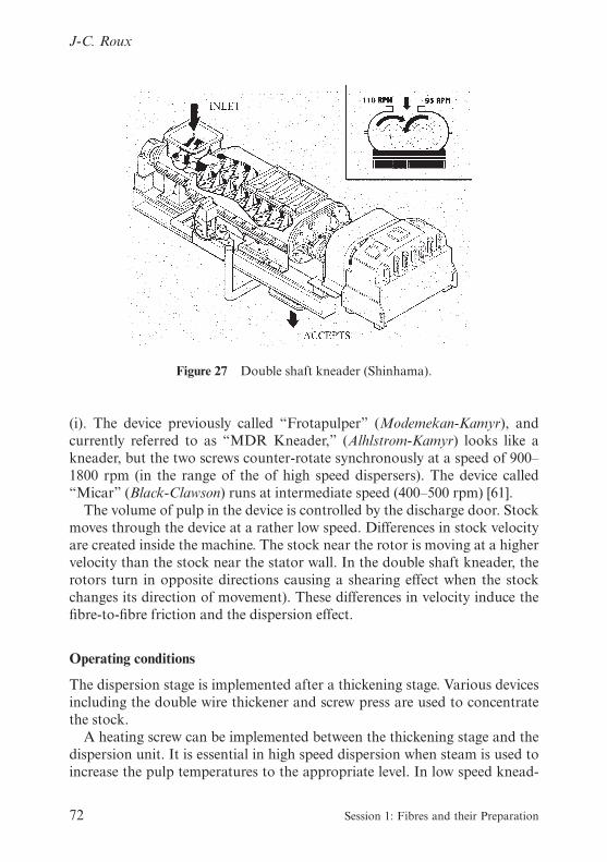
(i). The device previously called “Frotapulper” (Modemekan-Kamyr), andcurrently referred to as “MDR Kneader,” (Alhlstrom-Kamyr) looks like akneader, but the two screws counter-rotate synchronously at a speed of 900–1800 rpm (in the range of the of high speed dispersers). The device called“Micar” (Black-Clawson) runs at intermediate speed (400–500 rpm) [61].
The volume of pulp in the device is controlled by the discharge door. Stockmoves through the device at a rather low speed. Differences in stock velocityare created inside the machine. The stock near the rotor is moving at a highervelocity than the stock near the stator wall. In the double shaft kneader, therotors turn in opposite directions causing a shearing effect when the stockchanges its direction of movement). These differences in velocity induce thefibre-to-fibre friction and the dispersion effect.
Operating conditions
The dispersion stage is implemented after a thickening stage. Various devicesincluding the double wire thickener and screw press are used to concentratethe stock.
A heating screw can be implemented between the thickening stage and thedispersion unit. It is essential in high speed dispersion when steam is used toincrease the pulp temperatures to the appropriate level. In low speed knead-
Figure 27 Double shaft kneader (Shinhama).
72 Session 1: Fibres and their Preparation
J-C. Roux

ing, steam can be introduced at the kneader itself, and a heating screw is notgenerally required.
The dispersion consistency is generally 25–30%, with some devices operat-ing at up to 35–40%. Depending upon the pulp characteristics, some devicesare designed to operate at medium consistency.
The operating temperature depends on the requirements of the dispersionand varies over a wide range. Some kneaders are operated without any steaminput for deinking applications. In such cases, the increase of temperature (upto 40–60°C) arises from mechanical energy dissipation. Most applications usesteam to raise the dispersion temperature to approximately 90°C. Some lowspeed kneaders and high speed dispersers are designed as pressurized unitswhich can operate at temperatures up to 150°C. These conditions used to benecessary in asphalt dispersion.
For both types, the energy consumption is in the range of 35–100 kWh/t,with typical industrial values in the range 60–80 kWh/t. Various techniquescan be used to adjust the energy consumption depending on the device used.These approaches include adjusting the pressure on the discharge door, thegap between rotor and stator, the inlet consistency, etc.
In deinking plants, dispersion is often combined with bleaching. Bleachingchemicals can be introduced at the heating screw or at the inlet of the disper-sion unit, which functions also as a mixer or bleaching reactor. Dependingon the operating temperature and the device used, retention time may or maynot be required after the dispersion unit.
Generally the pulp discharged from a kneader does not require dilutionand bleaching is at the kneading consistency. The pulp can be discharged atoperating consistency in some high speed dispersers but generally dilution isrequired for discharging from these machines. In this case storage forextended bleaching is not possible.
CONCLUSIONS
Re-pulping (disintegration), refining or beating and hot dispersion are typic-ally pulp treatment processes and have been discussed in this part of thereview of Stock Preparation. As the subject is so wide, it was not the intentionof the author to be exhaustive. Emphasis was directed mainly on the processengineering aspects of the unit operations which do not often receive properattention. Chemical and physical-chemical aspects are beyond the scope ofthis paper, as are pulp dilution, transport and storage.
It is believed that substantial benefits are available to the papermaker whocorrectly re-pulps and disintegrates his pulps, whether virgin or recycled.
12th Fundamental Research Symposium, Oxford, September 2001 73
Stock Preparation Part 1 – Pulp Treatment Processes

Achieving the theoretical understanding on which to do this requires that theprocess must be defined as a triple operation where agitation by bulk motion,mixing and dispersion occur simultaneously. Then the physical description ofthe phenomena may be undertaken in order to model the kinetics. Modellingwhich concentrates on the total contact area between the solid and the rotor,allows us to understand the role of this parameter in a first-order kineticprocess, for each fibrous raw material chosen. Generalisation is then possibleif we take account of the wet tensile strength compared to the mechanicalforce applied.
However, as the consistency increases, the friction forces (solid/solid andsolid/liquid) are not confined to the surroundings of the rotor, but are presentalso throughout the whole volume. To allow for this situation, anotherapproach was followed, leading to a model for the kinetic constant in thefirst-order process as a function of the mass consistency and of the powerdissipated per unit volume. This model justifies performing pulp disintegra-tion in the medium consistency range. Based upon it, it becomes possible toclassify the propensity of a pulp to be disintegrated and the sensitivity to theconsistency; two parameters are hence needed.
Pulping or disintegration is a key operation for deinking in the case of allrecycled pulps. A rheological analysis based upon the globalisation of all thefriction forces leads to the shear-factor, from the generalisation of the appar-ent viscosity. Experimental trials performed in a planetary mixer equippedwith both a flat beater and a hook impeller on old newsprint papers deter-mined if ink fragmentation may result from mechanical action by bulk fric-tion. It was also found that the shear-factor is dependent on the nature of theimpeller and is an increasing function of the consistency. However, if oneconsiders the total amount of energy consumed whatever the consistency andtype of impeller, master curves are obtained which explain the disintegrationeffects, the brightness of the entire pulp and the speck contamination. It isalso proved that the planetary mixer is more efficient than the helical pulper.In the range of consistencies between 8–20%, model tools now exist for thepapermaker and for the machine manufacturer to assess the operation ofpulp disintegration in terms of pulp quality (lower contamination), higherproductivity and energy savings.
The refining/beating of pulps has always been one of the most funda-mental operations in the pulp treatment processes. The physical and almostmechanical characteristics for the pulp and the future sheet of paper areobtained at this stage. Despite its importance, it is also one of the moredifficult to understand and many contradictions are found in differentreported studies.
The purpose here was to analyse the physical phenomena in a global view
74 Session 1: Fibres and their Preparation
J-C. Roux

since it remains very difficult (even impossible?) to describe the micro-processes at the scale of the entities under concern: fibres or flocs.
For the case of a single disc refiner (which can easily be extended to includeconical refiners), a physical description of the global forces was given in termsof the tangential friction force, normal force, and friction coefficient. Fromthis theoretical analysis, some empirical results (e.g. Leider and Nissan,Banks, Dalzell) can be justified since some well-known expressions can benaturally and rigorously demonstrated.
The theory thus developed was then applied to reality in the form of anindustrial disc-refiner. By changing the widths of the bars and grooves, thenet power applied, the specific edge load, the mean crossing angle of the bars,the level of refining for the same fibrous raw material, a model was validatedto analyse the normal force applied and the gap clearance. Two parametersarose from this model: the maximum normal force (when the gap clearanceapproaches zero); and a parameter related to the change of pulp compress-ibility under refining conditions. A combination of both theory and practiceleads, for the first time, to the existence of a critical gap clearance underwhich the refining effects may occur on fibres. Interpretations in terms ofpressing and in terms of lubrication are then proposed. From these, the refin-ing kinetics may be interpreted in terms of the evolution of the global frictioncoefficient versus the gap clearance. At the beginning of the refining process,the physical phenomena are mainly solid/solid friction: the shortening effectson fibres reach their maximum and the friction coefficient decreases sharply.This regime then gives way to one where solid/liquid friction dominates,allowing the friction coefficient to reach a constant value. The first regimemay last so short a time that it is not observed in practice.
One fundamental result is obtained: the normal compression force is adecreasing linear function of the mean gap clearance. It is the understandingof the author that specific measurements must be developed and performedin order to be able to answer the practical and theoretical problems that areraised by the refining operation. Comparisons made with other mechanistictheories support the results proposed here.
When refining effects are studied, the importance of the concept of refiningintensity is often emphasised, but without any proper understanding of how itcan be defined and what it means physically. To contribute to better under-standing of this important concept, this paper built up from first principlesexpressions for the normal (frictional) force and the normal force divided bythe average number of bar crossings. These provided the foundations on whichto develop the concept of the reference specific edge load, which now becomesa theoretical concept rather than an empirical convenience. Some conclusionsare also given regarding the specific surface load and the impact length.
12th Fundamental Research Symposium, Oxford, September 2001 75
Stock Preparation Part 1 – Pulp Treatment Processes

When developing theories about refining, it is also difficult to transformbar crossings into impacts on fibres. The C_ factor analysis can contribute tothis, though there are some discrepancies where geometrical angle parameters(particularly grinding and sector angle) are concerned.
Finally, some considerations on the distribution of intensity are given, andreferences to recent literature discussing optimal values both for the intensityand for the specific energy are given.
Historically, dispersion at high temperature was used to disperse bitumenwhen recycling asphalt impregnated papers. More recently, it has becomecommonly used to disperse other contaminants such as wax and hot meltglues, especially in recycling old corrugated containers (OCC).
For white recycled grades, hot dispersion was found useful to disperse hotmelt contaminants, and to improve the visual appearance of the final sheet byreducing residual ink and specks. However, because dispersion does notremove contaminants, but disperses them into the pulp, it can induce somedetrimental effects such as deposits on the papermachine. As a consequenceof the progress made in cleaning and screening efficiency, the value of hotdispersion is now being questioned.
The future of hot dispersion is mainly related to the improvement of deink-ing technology. Both high speed dispersers and low speed kneaders are pro-posed as ways of improving ink detachment, mainly before post-flotation.Various dispersing and kneading technologies are available and the choice ofthe most effective type is the subject of debate. The important role of dis-persers as mixers and reactors for bleaching chemicals is also emphasised.
New applications, such as microbiological decontamination by using chem-icals in a kneader, has also been proposed, and will probably be an importanttopic in the near future.
REFERENCES
Re-pulping/disintegration operation
1. de Choudens, C., Angelier, R., Combette, Ph., “Pâtes mécaniques de résineux,pâtes chimicomécaniques de feuillus. Nouveau procédé de fabrication”, RevueATIP, 38(8): 405–416, Septembre/Octobre (1984).
2. Kurdin, J.A., Bohn, W.L., “Mechanical pulping by extrusion”, Tappi PulpingConference, proceedings: 265–274, San Francisco, November 12–14 (1984).
3. de Choudens, C., Angelier, R., “Bleached high yield pulps with the bivis processconstituted of two bivis machines in line”, Das Papier, 43(10A): 8–12 (1989).
4. de Choudens, C., Angelier, R., Devic, M., Kervennal, J., “Chemical-thermo-mechanical pulps at high level of brightness obtained by the bivis process associ-ated with a sulfonation in reducing medium”, Paperi ja Puu, 72(3): 248–252 (1990).
76 Session 1: Fibres and their Preparation
J-C. Roux

5. de Choudens, C., Angelier, R., Brochier, R., Labalette, F., “Manufacture ofunbleached high yield pulps for packaging papers by the bivis process from fibresorghum”, 1st European Seminar on Sorghum for Energy and Industry, Toulouse,1–3 April (1996).
6. de Choudens, C., Angelier, R., “The manufacture of bleached chemical pulps forprinting grades from annual plants by the bivis process”, International Conferenceon Sustainable Agriculture for Food, Energy, and Industry, Braunschweig, June 27–28 (1997).
7. Roux, J.C., “How to characterise the operation of disintegration?”, Paper Engin-eering Seminar, Terrassa, Spain (1999).
8. Peel, J.D., “Stock preparation”: Paper Science and Paper Manufacture, Gary A.Smook (ed. ?): Angus Wilde Publications Inc., p. 99 (1999).
9. Barfod, H., “Modern integrated broke handling systems”, Pulp and Paper Can-ada, 87(5): p. 74 (1986).
10. Lamort, P., Lamort de Gail, P., “Re-pulping of wet-strength paper and paper-board with medium consistency pulping”, Papier Carton et Cellulose, 29(4):p. 60–61 (1980).
11. Paraskevas, S., “High consistency re-pulping benefits and drawbacks”, TappiPulping Conference, Houston: p. 139–143 (1983).
12. Holik, H., “Towards a better understanding of the defibreing process”, TappiEngineering Conference, Chicago: p. 223–232 (1988).
13. Wagle, D.G., Lee, C.W., Brodkey, R.S., “Further comments on a visual study ofpulp floc dispersion mechanisms”, Tappi J., 71(8): pp. 137–141 (1988).
14. Bennington, C.P.J., Smith, J.D., Sui, O.S. and Wang, M.H., “Characterization ofre-pulper operation for newsprint deinking”, Tappi Pulping Conference, Montréal,3: p. 1083–1095 (1998).
15. Amaral, M.E., Renaud, M., Roux, J.C., “Cinétique de désintégration des pâtes àpapier: modélisation du phénomène”, Revue ATIP, 54(3–4): pp. 76–84 (2000).
16. Fabry, B., “Etude de la rhéologie des suspensions fibreuses concentrées dans le butd’améliorer le recyclage des papiers”, Thèse de Doctorat de l’INPG en Génie desProcédés, Grenoble (1999).
17. Fabry, B., Roux, J.C., Carré, B., “Characterization of friction during pulping: aninteresting tool to achieve good deinking”, Journal of Pulp and Paper Science,foreseen in autumn 2001.
18. Merrett, K.J., “Repulping at high consistencies”, Appita, 40(3): pp. 185–188 (1987).19. Savolainen, A., Jussila, T., Nikula, S., “Defibreing and specific energy consump-
tion in bale pulpers”, Tappi J., 71(11): pp. 147–153 (1991).20. Fabry, B., Roux, J.C., Carré, B., “Pulping, a key-factor for optimising deinking”,
Congrès de l’ATIP, Bordeaux (2000).21. Sousa-Santos, A., “Le rôle des tensio-actifs dans la flottation des encres off-set
lors du désencrage des fibres cellulosiques”, Thèse de Doctorat de l’INPG en Géniedes Procédés, Grenoble: 1997.
22. Metzner, A.B., Otto, R.E., “Agitation of Non-Newtonian fluids”, Journal ofAmerican and Engineering Chemistry, 43(3): pp. 3–10 (1957).
12th Fundamental Research Symposium, Oxford, September 2001 77
Stock Preparation Part 1 – Pulp Treatment Processes

Refining/beating
23. Ebeling, K., “A critical review of current theories for the refining of chemicalpulps”, International Symposium on Fundamental Concepts of Refining, Appleton:pp. 1–33 (1980).
24. Page, D.H., The beating of chemical pulps – the action and the effects, C.F. Bakerand V.W. Punton (eds.): Mechanical Engineering Publications Limited: pp. 1–38(1989).
25. Hietanen, S., Ebeling, K., “Fundamental aspects of the refining process”, Paperija Puu – Paper and Timber, 72(2): pp. 158–179 (1990).
26. Fox, T.S., Brodkey, R.S. and Nissan, A.H., “Inside a disk refiner”, Tappi J., 65(7):pp. 80–83 (1982).
27. Steenberg, B., “Review of the effect of mechanical treatment of fibres”, SvenskPaperstidning, 66(22): pp. 933–939 (1963).
28. Giertz, H.W., “Ännu ett sätt att se pa° malningsprocessen”, Norsk Skogindustri,18(7): pp. 239–248 (1964).
29. Roux, J.C., Chu, J.P., Joris, G., Caucal, G., “Théorie hydro-mécanique dufonctionnement d’un raffineur à basse concentration”, Revue ATIP, 53(4–5):pp. 106–116 (1999).
30. Banks, W.A., “Design considerations and engineering characteristics of discrefiners”, Paper Technology, 8(4): pp. 363–369 (1964).
31. Dalzell, D.R., “A comparison of paper mill refining equipment”, Tappi J., 44(4):pp. 241–244 (1961).
32. Radoslavova, D., Roux, J.C., Silvy, J., Hydrodynamic modelling of the behaviour ofthe pulp suspensions during beating and its application to optimising the refiningprocess, C.F. Baker (ed.): Pira International: pp. 607–639 (1997).
33. Roux, J.C., “La rhéologie pour mieux comprendre le fonctionnement des raff-ineurs en papeterie”, Les Cahiers de Rhéologie, 17(1): pp. 163–174 (2000).
34. Leider, P.J., Nissan, A.H., “Understanding the disk refiner – the mechanicaltreatment of the fibres”, Tappi, 60(10): pp. 85–89 (1977).
35. Wahlström, P.B., Pulp and Paper Magazine of Canada, 60(8): pp. 379–401 (1960).36. Caucal, G., Chaussy, D., Renaud, M., “Mesure des pulsations de pression
en différents points d’un raffineur à disques”, Revue ATIP, 46(5): pp. 130–138(1992).
37. Goncharov, V.N., “Force factors inside a disk refiner and its effect on the beatingprocess” (translation), Bumazh. Prom., (5): pp. 12–14 (1971).
38. Martinez, D.M., Batchelor, W.J., Kerekes, R.J., Ouellet, D., “Forces on fibres inlow-consistency refining: Normal Force”, Journal of Pulp and Paper Science,23(1): pp. 11–18 (1997).
39. Charuel, R., Roux, J.C., de Agostini F., Rousselle-Manuel, C., “Influence de lagéométrie des lames sur le raffinage des pâtes chimiques”, Revue ATIP, 42(4):pp. 153–160 (1988).
40. Wultsch, F., Flucher, W., “The small Escher Wyss refiner as a standard testinginstrument for modern stock preparation plant”, Das Papier, 12(13–14):pp. 334–342 (1958).
78 Session 1: Fibres and their Preparation
J-C. Roux

41. Brecht, W., Siewert, W., “Zür theoretisch-tecnisen Beurteilung des Mahlprozessesmoderner Mahlmaschinen”, Das Papier, 20(1): pp. 4–14 (1966).
42. Smith, S., The action of the beater, Tech. Sect. Brit. Paper Makers’s Assocn.:Great Britain and Ireland: 212 p: 1923.
43. Roux, J.C., Joris, G., Caucal, G., “Angular parameters beyond specific edge load”,The 6th Pira International Refining Conference, Toronto (2001).
44. Roux, J.C., “Hydro-mechanical approach to understand the refining phenom-ena”, COST Meeting E7, Technical University of Dresden: 25 May (1999).
45. Lumiainen, J., “A new approach to the critical factors affecting the refiningintensity and refining result in low-consistency refining”, Tappi Papermakers Con-ference, pp. 269–278 (1990).
46. Kerekes, R.J., “Characterisation of pulp refiners by a C-factor”, Nordic Pulp andPaper Research Journal, 1 (1990).
47. Lewis, D.W., Danforth, J., “Stock preparation analysis”, Tappi J., 45(3): pp. 185–192 (1962).
48. Croney, C, Ouellet, D., Kerekes, R.J., “Characterizing refining intensity for tensilestrength development”, 5th International Paper and Board Industry Conference,Scientific and Technical advances in refining, Vienna: 29–30th April (1999).
49. Roux, J.C., Mayade, T.L., “Modeling of the particle breakage kinetics in the wetmills for the paper industry”, Powder Technology, 105: pp. 237–242 (1999).
Hot dispersing/mixing
50. Galland, G., Carré, C., Cochaux, A., Vernac, Y., Julien Saint-Amand, F., “Disper-sion and Kneading”, Paper Recycling Challenge.
51. Higgins, J.J., “Use of the asphalt dispersion system on waste paper”, Tappi,43(1):132A-133A, January (1959).
52. Muir, J., “Processing of mixed waste paper”, Paper Technology, 8(3): 265–269(1967).
53. Van Guelpen, L.C., “Dispersion of asphalt materials in paper stocks”, Tappi,43(11): 162A-165A, November (1960).
54. Ortner, H., “Dispersion as a means of quality improvement of de-inked stock”,Paper Technology and Industry, 19(5): 143–147, May-June (1978).
55. Lamort de Gail, B. and Hétier, F., “Use of hot-dispersion system in treatment ofsecondary fibres”, Paper Technology and Industry, 19(2): 48–56, February (1978).
56. Cropper, M.A., “Advances in deinking and its use in improving quality of news-print”, Tappi Paper Makers Conference, 93–96, Atlanta, 26–29 April, (1976).
57. Ortner, H. and Fisher, S. , “Der Einsatz der Dispergierung zur Qualitätsverbesse-rung von deinkten Stoffen”, EUCEPA Symposium, Ljubljana 23–27 October,(1989), Book of papers, V.II: 419–452 also see Wochenblatt für Papierfabrikation,117(19): 855–862, October (1989).
58. Linck, E., Matzke W. and Siewert W., “Systemüberlegungen beim Deinkingvon Altpapier”, EUCEPA Symposium, Ljubljana (23–27 October 1989), Book of
12th Fundamental Research Symposium, Oxford, September 2001 79
Stock Preparation Part 1 – Pulp Treatment Processes

papers, V.II: 361–378 also see Wochenblatt für Papierfabrikation, 118(6): 227–232(March 1990).
59. Johansson, O. and Steffner, S. , “Field Experience Gained in the New DeinkingPlant at Hylte Bruks AB”, EUCEPA Symposium, Ljubljana, 23–27 October (1989).
60. Galland, G., Vernac, Y., Bernard, E. and Alibaux, P., “Amélioration de lablancheur des pâtes désencrées”, EUCEPA Symposium, Ljubljana (23–27 October1989), also see revue ATIP 44(3): 149–158 (March 1990).
61. McBride, D., “High-Density Kneading: an Alternative to Dispersion”, 1993Tappi Recycling Symposium, Notes: 173–180. New Orleans (28 February–4 March1993).
62. McCarthy, C.E., “Dispersion and kneading”, Tappi Deinking Short Course,Houston, Wyndham Greenspoint Hotel, 10–12 June (1996).
63. McKinney, R. and Roberts, M., “Curl in recycled fibre: the impact of dispersionand kneading”, Paper Recycling ’96 Conference, Lancaster Hotel, London, 13–14November (1996).
64. Cochaux, A., Carré, B., Vernac, Y. and Galland, G., “What is the differencebetween dispersion and kneading?”, Progress in Paper Recycling, 6(4): 89–101,August (1997).
65. Sferrazza, M., Floccia, L., Favier, P. and Rihs, J., “Dispersion without dewater-ing: an innovative new approach”, Paper Recycling ’96 Conference, LancasterHotel, London, 13–14 November (1996).
80 Session 1: Fibres and their Preparation
J-C. Roux

STOCK PREPARATION PART 1 – PULPTREATMENT PROCESSES
Jean-Claude RouxEcole Française de Papeterie et des Industries Graphiques
Joint Comment submitted by J-C. Roux and R.J. Kerekes
This note is to clarify a statement concerning the C Factor on page 65 of thispaper: “. . . .despite the rigour of the analysis used to derive the formula forthe C factor, it does not agree with experimental results when the angularparameters . . . are varied.”“ . . . increasing these angles leads to a decrease in the shortening effect . . .this means that an increase in the number of impacts should be observed. . .”
The C-Factor in fact correctly predicts this trend. For angles in the practicalrange, up to 52 degrees (combined angle), it predicts the number of barcrossings to increase with angle, and therefore intensity to decrease. Thisleads to a decrease in fibre shortening. The theory further predicts that thenumber of bar crossings reaches a maximum at about this angle. Beyond thisvalue, the number of bar crossings decreases. In the limit of 180 degreescombined angle, it reaches zero. In this case the bars are concentric rings onthe refiner plate, and therefore cannot create any bar crossings at all.
Kari Ebeling UPM-Kymmene Corporation
Could you please comment on the refining part of your presentation? Howdoes the critical gap depend on the flocculation state? There has been photo-graphic research done which shows that in the beginning of the refining barsare treating flocs – not individual fibres?
Jean-Claude Roux
I understand your question. In fact you saw that we decided to globalise thephenomena so I can come back to Figure 17 which expresses the forces or the
12th Fundamental Research Symposium, Oxford, September 2001
Transcription of Discussion

inverse of the normal forces versus the gap clearance. You can see that in thiscurve there is one delta parameter that is proportional to the slope of thiscurve. We have not exactly the same behaviour for softwood or hardwood; Ishowed this CTMP pulp because we have plenty of results on this kind ofpulp, but we also made interpretation on all kinds of fibrous raw materials. Imean the delta parameter is typically for raw material and it expresses somekind of compressibility the fibre pads in the inter-crossing zones, but it is aglobal view, you are right it depends on the state of flocculation. I know thatthere is some work on this subject to decided what is a consistency of the pulppad or of the entities because you know it is a matter of speculation. Prof.Duffy, my colleague, put a classification of five types of flocs and probablyten types of flocs; what is a floc, it is a question probably that has been raisedmany times, but that is the reason why it is impossible for me to decide what isa kind of entity, and what is a type of floc. We measure only the delta whichexpresses the compressibility of the entities in the entire crossing zones. Andthis delta value is of course depending on the fibrous raw material.
Chad Bennington University of British Columbia and Paprican
I have one comment. You refer to work I have done to develop a model fordeflaking, show a figure (Figure 3, Volume 1, Page 25) that summarizes someof my data, and discuss generating a master curve. If you take into accountthe wet-tensile strength of the paper and the maximum force generated by therotor, you can collapse all these individual curves into one master curve. Weare then in the same situation as you are, with a master curve that can predictthe extent of paper deflaking. The shear-factor approach you have developedusing Metzner and Otto averages out the shear rate in the vessel. Our modelconsiders the maximum force generated at the rotor-suspension interfacewhich is related to a characteristic shear rate in the vessel. I still think it isunclear whether deflaking is due to the application of this maximum force, orto a bulk shear rate. Both methods are actually related.
Jean-Claude Roux
Yes you are right, we can obtain some master curves if we take into accountthe wet tensile strength for different raw materials, and I know also that if weincrease the consistency we have the inter-friction of fibre which is of import-ance and in your model you have put it in the maximum force, and also theeffects are maximum around the volume of the rotor, and so I know that, butin your model you have one kind of rotor and what I have shown after that itis possible to integrate in a first order kinetic process also all the types of
Discussion
Session 1

rotor by modelling the first order rate by the same expression which I wasvery surprised by this result, but I have to mention that it is true also for somesmall laboratory mixer, big pulper of any kind of size, according to me whatis the one relevant parameter is the accumulated energy consumed pervolume of pulp suspension.
Stock Preparation Part 1 – Pulp Treatment Processes
12th Fundamental Research Symposium, Oxford, September 2001