sto-2 electronics reference document
TRANSCRIPT

STO-2 Electronics Reference Document
Version – Date Description Author
1.0 – 6/22/2011 1st draft C. Kulesa
1.1 – 6/23/2011 Text cleanup C. Kulesa
1.2 – 7/7/2011 Pre-meeting changes C. Kulesa
1.3 – 7/10/2011 Post meeting changes, prepping for addingremaining documentation.
C. Kulesa
1.9 – 7/24/2011 Combining document draft C. Kulesa
1.95 – 7/26/2011 Added section on MKS housekeeping C. Kulesa
1.96 – 7/29/2011 Added cable lengths; changed pinouts to reflectRobert's optics box schematic
C. Kulesa
1.97 – 7/31/2011 Added DE9 assignments to Ball H/K (not 1:1) C. Kulesa
1.98 – 7/31/2011 Lemo power starts with pin1=24VDC, pin2=GND.Electronics box power cable is a 2x0b Lemo.
Power cable lengths specified.
C. Kulesa
1.99 – 8/3/2011 Changed synthesizer & IF temp/dcdc pinouts onsubD
R. Stickney
1.999 – 8/5/2011 Changed Lemo side of synth connector to reflectexisting RF box wiring, no impact on DA15
C. Kulesa
2.0 – 11/20/2011 Changed ASU/IF box pinouts to reflect wackypinouts on Robert's MUX board
C. Kulesa
3.0 – 5/20/2014 Beginning of overhaul for STO-2. Added summaryof each electronics box, capabilities, issues, and
changes for STO-2.
C. Kulesa
4.0 – 7/19/2015 Removed STO-1 references. First complete draft forSTO-2 in preparation for cable reworking.
C. Kulesa
4.1 – 8/6/2015 JPL box cable length from 4’ → 6’QCL temp sense moves to different cable (18)
Fixed power consumptions in OverviewChanges to cables 4, 5, 8, 18
C. Kulesa
4.2 – 8/12/2015 Fixes based on actual wiring: changes to cable 8 C. Kulesa
4.3 – 11/24/20154.4 – 11/27/2015
Changes to Cable 18: add QCLChanges to SRON Cable #18, 20: tmp sense and I/O
Specify draft for SRON-to-dewar harness #35 Monitoring SRON FLL IF in XPV (cable #34)
PID (cable #4) brings 5th output to QCL voice coil
C. Kulesa
4.5 – 11/30/2015 Changes to cable #19 as wired (XL6 to XL5, notwired 1:1)
Update all 3 system diagrams Add internal JPL synth wiring for SPI
C. Kulesa

Overview – Systems Diagram
Figure 1: System diagram highlighting the distributed STO-2 instrument signaling and control. Power connections are near-transparent and highlighted inFigure 3.

Overview – Description of Electronics Boxes
Instrument Command and Control Box
Electrical Requirements 24VDC at 1A, 1x ethernet in
Mechanical Requirements Flat plate mounting space w/ 1/4-20 (?) tapped holes
Thermal requirements 25W dissipated, not to exceed 60C
Capabilities:- "Nerve center": Origin of all digital control signals and destination of all instrument housekeeping. - Instrument control computer (ARM9) creates all digital buses and com links.- Supercam bias electronics card provides 8 channels of biases for HEB mixers, mixer heaters & LNAs- DC Electronics board provides DSUB interfaces to all external components, readout of AD590 temp sensors scattered around instrument.- Reworked temperature monitor (Lakeshore 208 core) reads DT470 silicon diodes in dewar.- PID closed-loop biasing of 8 LO multipliers based upon analog mixer current. - Lids are radiation shields and a cooling path in flight.
Optics Box
Electrical Requirements 24VDC at 0.5A (2A max)
Mechanical Requirements Flat plate mounting space with 1/4-20 tapped holes
Thermal requirements 10W dissipated, baseplate never to exceed 60C
Capabilities:- Supplies Schneider/IMS stepper motor with power and communication (RS422) - Supplies drive voltage to 2 Hall effect sensors, for stepper drive homing
SRON 4.7 THz Receiver Box
STO-1 Electrical Requirements 24VDC at 2.5A
Mechanical Requirements Flat plate mounting space with 1/4-20 tapped holes
STO-1 Thermal requirements 55W dissipated, baseplate never to exceed 60C
Capabilities:- 1 LO drive tone at up to 25 dBm output, from 9-16 GHz depending on MLSN synthesizer used- Phase noise less than -100 dBc at 10 KHz- Two PID loops for amplitude and frequency stabilization of the SRON QCL LO- Source of the instrument’s distributed 10 MHz reference oscillator- Support systems for Omnisys ASIC correlator (0-4 GHz IF) and SRON-data computer (TS-7200)- Lids are radiation shields and a cooling path in flight.
IF Amp Box
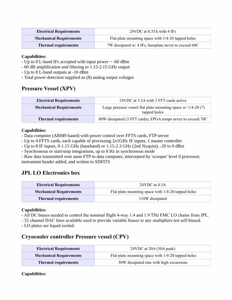
Electrical Requirements 24VDC at 0.35A with 4 IFs
Mechanical Requirements Flat plate mounting space with 1/4-20 tapped holes
Thermal requirements 7W dissipated w/ 4 IFs, baseplate never to exceed 60C
Capabilities:- Up to 8 L-band IFs accepted with input power ~ -60 dBm - 60 dB amplification and filtering to 1.15-2.15 GHz output- Up to 8 L-band outputs at -10 dBm- Total power detection supplied as (8) analog output voltages
Pressure Vessel (XPV)
Electrical Requirements 24VDC at 3.2A with 3 FFT cards active
Mechanical Requirements Large pressure vessel flat plate mounting space w/ 1/4-20 (?)tapped holes
Thermal requirements 80W dissipated (3 FFT cards), FPGA temps never to exceed 70C
Capabilities:- Data computer (ARM9 based) with power control over FFTS cards, FTP server- Up to 4 FFTS cards, each capable of processing 2x1GHz IF inputs, 1 master controller- Up to 8 IF inputs, 0-1.15 GHz (baseband) or 1.15-2.3 GHz (2nd Nyquist), -20 to 0 dBm- Synchronous or start/stop integrations, up to 8 Hz in synchronous mode- Raw data transmitted over anon FTP to data computer, intercepted by 'scooper' level 0 processor, instrument header added, and written to SDFITS
JPL LO Electronics box
Electrical Requirements 24VDC at 4.5A
Mechanical Requirements Flat plate mounting space with 1/4-20 tapped holes
Thermal requirements 110W dissipated
Capabilities:- All DC biases needed to control the nominal flight 4-way 1.4 and 1.9 THz FMC LO chains from JPL.- 32 channel DAC lines available used to provide variable biases to any multipliers not self-biased.- LO plates are liquid cooled.
Cryocooler controller Pressure vessel (CPV)
Electrical Requirements 24VDC at 20A (30A peak)
Mechanical Requirements Flat plate mounting space with 1/4-20 tapped holes
Thermal requirements 50W dissipated rms with high excursions
Capabilities:

- Contents include two active dampener cryocooler controllers from Sunpower
Power Conversion and Control – System diagram
The STO-2 flight system has a highly distributed power control system allowing finely-grained control over the experiment. The gondola system bias is nominally unregulated 24-28VDC; this bus is distributed to the instrument through a series of gondola circuits which are individually addressable through the CSBF SIP (Figure 2).
Each of the instrument electronics boxes takes as its input the gondola 24-28VDC bus. The internal wiring of the instrument boxes is shown in Figure 3. All of the “P” harnesses save P9 and P10 go to the 24VDC gondola bus power system. P1 (XPV) goes to a separate 20A circuit; the others go to one of two 20A breakout power strips that are switched simultaneously.
Figure 2: Gondola-to-instrument power distribution system

Internal to each box is a highly distributed power system which takes 24VDC as input and generates over 16 different device voltages at the point of load. Each of these power modules are based on switching buck/boost converters and feature a TI (if unipolar) or Murata (if bipolar) DC/DC converter preceded and followed by a tuned Pi filter to eliminate switching noise and followed by additional output capacitance to provide smooth DC output.
Figure 3: System diagram highlighting the instrument’s 24V power distribution system. Save P1, which has its own 20A circuit and P9/P10 which are internal harnesses for the cryocoolers, all power harnesses terminate on the two 20A power strips provided by the gondola PDU.

Box Mount Orientation
Figures 5-7 shows the established mounting of the Command and Control (C&C) box, the SRON Receiver box, and the ASU IF box, relative to the centrally-located optics box, the APL bulkhead connector panel, and the Ball housekeeping breakout cables and MKS sensors and controllers.
Figure 4: A sample of SORAL DC/DC converter boards. Top row shows a "large" unipolar module with 6A capability and a "small" module at 1.5A. Middle row shows "large" and "small" bipolar supplies, and at bottom, large and small bare boards.

Figure 5: Locations of the instrument electronics boxes as seen from the top (l) and bottom (r) of the telescope.
Figure 6: Locations of the instrument electronics boxes as seen from the front of the telescope.
Figure 7: Locations of the instrument electronics boxes as seen from the back of the telescope.

Signal Cables
Figure 8 shows an indexed guide to the cables for reference.
Interfaces to Cryocooler Pressure Vessel (CPV)
1. Two serial RS-232 connections from the C&C box to command and monuitor the Sunpower AVC controllers in the CPV. See Figure 9. (CABLES 1 & 2)
Figure 8: System diagram of external instrument signal cables, as per Figure 1 but indexed by cable for easier reference. Power cables are listed in Figure 3.

2. Signal harnesses A and B from the milspec 16-32 hermetic to the QCL and OVCS coolers (Cables 22, 23 – see CPV ICD).
Interfaces to JPL LO Box
1. 5 PID outputs from the C&C box travel over 4 2-conductor cables. One PID output pair is buffered through a SRON voice coil driver and Y's to BNC output after leaving the C&C box. Box panel receptacles on the JPL box are ECG.2B.310.CLL and EGG.2B.310.CLL on the C&Cbox. Mating cable connectors are FGG.2B.310.CLAD62. See Figure 10. (CABLE 4)
Pin Description
1 PID Out 1 [NII]
2 PID Out 2 [NII]
3 PID Out 5 [CII]
4 PID Out 8 [CII]
5 PID return 1 (AGND)
6 PID return 5 (AGND)
7 PID Out 7 [OI] – to QCL breakout
8 PID return 7 (AGND)
9,10 N/C
Figure 9: Serial cables from C&C box to cryocooler controller pressure vessel (CPV)

2. Synthesizer cable provides SPI-bus control over the Microlambda and PhaseMatrix synthesizers in the JPL and SRON boxes. We combine both synthesizer controls to one DA15 connector on the C&C box. See Figure 11. (CABLE 5)
DA15Pin
Function Location miniXLpin
1.4 THzSynth
1.9 THzSynth
DIO assigned
1 SPI SCK (W) any 1 9 20 DIO_2_0
9 SPI MOSI (W) any 2 10 22 DIO_2_1
2 SPI MISO (R) any 3 14 24 DIO_2_2
10 SPI SEN1 (W) 1.4 THz synth 4 11 – DIO_2_3
3 SPI SEN2 (W) 1.9 THz synth 5 – 18 DIO_2_4
Figure 10: Cable 4 is a 4-output PID output cable from C&C box to JPL LO box.
Figure 11: Cable 5 provides SPI bus control to the Microlambda and PhaseMatrix synthesizers.

3. The external I2C bus cable provides the JPL LO box with local I2C control over the multichannel DAC needed to drive variable power supplies and any directly-biased multipliers. See Figure 12. (CABLE 6)
Pin Signal
1 +5V I2C
2 I2C SDA buffered
6 I2C SCL buffered
7 DGND
5 I2C SDA unbuffered (not used in flight)
9 I2C SCL unbuffered (not used in flight)
4. Temperature sense cable supplies a global 15V to remotely-installed AD590 sensors and returns the current from each sensor to be read by a precision resistor in the C&C box and multiplexed for ADC readout. Two sensors continue beyond the JPL LO box to the optics box. See Figures 13-14. (CABLE 7 and CABLE 9)
Pin Cable 7 Function Location MUX assigned
1 VCC (12-15V)
2 TMP SENSE 1 1.4 THz synth Mon_4_0
3 TMP SENSE 2 1.4 THz PA Mon_4_1
4 TMP SENSE 3 1.9 THz synth Mon_4_2
5 TMP SENSE 4 1.9 THz PA Mon_4_3
6 TMP SENSE 5 Optics: Calibration load Mon_4_4
7 TMP SENSE 6 Optics: Stepper motor case Mon_4_5
8 Analog 1 Quinstar current monitor Mon_4_6
9 Analog 2 MP amp current monitor Mon_4_7
Figure 12: Cable 6 provides a remote I2C bus to the JPL LO box for operation of the bias DAC.

Pin Cable 9 Function Location
1 VCC (12-15V)
2 TMP SENSE 5 Calibration load
3 TMP SENSE 6 Stepper motor
5. Power control cable provides 5 switchable DC/DC enable lines. See Figure 15. (CABLE 8)
Pin Function Attached device to be switched DIO assigned
1 8V @ 1A 1.4 THz AMC-10 OD_7_0
2 5, 15V @5A 1.4 THz Microlambda OD_7_1
3 5V @ 5A 1.4 THz Quinstar OD_7_2
4 12V @ 5A 1.9 THz PhaseMatrix OD_7_3
5 9V @ 5A (x2) 1.9 THz MD power amp OD_7_4
Figure 13: Cable 7 provides temperature monitoring of the AD590 sensors in the JPL LO box.
Figure 14: Cable 9 extends cable 7's temp sensing from the JPL box to the optics box.

6 N/C
Interfaces to Optics Box
1. 1 x RS422 connection, multiplexed to the Schneider/IMS NEMA23 integrated stepper controllers, from the one USB port of the TS-7200 brought external to the C&C box, addressedas a generic USB device at /dev/ug0 under NetBSD. See Figure 16. (CABLE 13)
2. Temperature monitor cable has already been discussed (CABLE 7, Figure 12).
Figure 16: Cable 13 provides C&C->Optics control of the flip mirror via USB RS-422 control.
Figure 15: Cable 8 provides power control over the JPL LO box.

Interfaces to SRON Box
1. Microlambda synthesizer SPI control sent over a DA15 connector from the C&C box (sharedw/ JPL box, see Figure 11 and CABLE 5). Below are the pin assignments for the SRON box Lemo EGG.1B.306 connector. N.B. DIO3_5 must be wired directly in the C&C box (if used)!
DA15 Pin Function Location Lemo 306 DIO assigned
6 SPI SCK (W) any 1 DIO_3_0
14 SPI SDI (W) any 2 DIO_3_1
7 SPI SDO (R) any 3 DIO_3_2
15 SPI SEN1 (W) 4.7 THz Microlambda 4 DIO_3_3
8 SPI SEN2 (W) QCL LO bias DAC 5 DIO_3_4
13 SPI SEN3 (W) Hittite IF proc LO 6 DIO_3_5
2. Temperature sensor and power control 1 cable for SRON box, terminated in DE9 and Lemo connectors with at least 3 pins for 2 x AD590 sensors and TTL level switching of DC/DC converters for two RF/LO functions. The temp sense lines return to the multiplexer where the current is measured from the potential across a precision resistor. See Figure 17. (CABLE 20)
DE9 Pin Function Location Lemo 310
1 VCC (12-15V) 1
2 TMP SENSE 1 Base Plate 2
3 TMP SENSE 2 Microlambda 3
4 TMP SENSE 3 IF amps 4
5 TMP SENSE 4 FLL bipolar supply 5
Pin Power ctrlr tobe switched
Attached device to beswitched
6 +5V @5A+15V @5A
4.7 THz Microlambda 6
7 +/-15V @2A Freq lock loop box,10MHz ref, superlattice
7
8 +/-15V @0.5A QCL Bias drive 8
9 AGND reference 9

3. The Power control 2 cable for the SRON box comes from a mini-XL-6 connector on the C&C box and terminates in a mini-XL-5 on the SRON box. Pins 3 and 4 are reversed as wired. See Figure 18 and pinout below. (CABLE 19)
XL6Pin
XL5pin
Function Attached device to be switched Assigned I/O
1 1 5V @ 5A1.8V @ 10A
TS-7200 “SRON-data” and correlator OD_7_5
2 2 9V@5A Spacek power amp on 200 GHz source OD_7_6
3 4 12V@5A IF amps (and IF proc, not flying) OD_7_7
4 3 Analog in 1 QCL Bias monitor ADC 5 MUX 8
5 5 Analog in 2 QCL Freq Lock status ADC 5 MUX 9
Figure 17: Cable 20 brings the SRON box temperature sensor monitoring and partial DC/DC converter power control.
Figure 18: Cable 19 brings the SRON box remaining power control lines and general purpose DIO.

4. SRON BOX to QCL breakout & Superlattice: This cable supplies signaling and power to the QCL breakout box and the JPL 200 GHz source for the superlattice. Terminated at the SRON box in a 6-pin mini-XLR and a BNC, it diverges into BNCs and a 3 pin mini-XLR. Cable 35, see Figure 19.
Connections to ASU's IF Box
1. IF total power monitor for HEB channels, terminated in DE9 on the DC electronics box and on the IF box. The analog lines terminate in the DC electronics box interface module's analog multiplexer. See Figure 20. (CABLE 14)
ASU BoxPin
DCE Boxpin
Assignment Description
1 9 MON 8 Channel 8 total power
2 4 MON 7 Channel 7 total power
3 8 MON 6 Channel 6 total power
4 3 MON 5 Channel 5 total power
5 7 MON 4 Channel 4 total power
6 2 MON 3 Channel 3 total power
7 6 MON 2 Channel 2 total power
8 1 MON 1 Channel 1 total power
9 5 Chassis GND
Figure 19: Cable(s) 35 connects all DC signal and power connections to the superlattice and QCL breakout box.

2. Temperature sensor and power control cable for IF box, terminated in a Mini-XL connector with 6 pins for 2 x AD590 sensors and 2 TTL level switches for DC/DC converters. The ground and tmp sense lines return to the multiplexer where the current is measured from the potential across a precision resistor. Note that we are replacing the ASU 3-pin mini-XL connector with a 6-pin equivalent to accommodate the new functions. See Figure 21. (CABLE 15)
Mini-XLPin
Function Location DE9 Pin
1 VCC (12-15V) 1
2 TMP SENSE 1 IF plate 2
3 TMP SENSE 2 5V or 15V DC/DCconverter
3
Mini-XLPin
Power ctrlr tobe switched
Attached device to beswitched
DE9 Pin
4 +3V @5A All minicircuits amps 4
5 +/-15V @0.5A Power monitoring circuit 5
6 AGND reference 9
Figure 20: Cable 14 brings total power analog signals from the IF box to the C&C box for monitoring.

Connections to Ball Dewar
1. DT470 silicon diode temperature sensors and American Magnetics helium level sensor are monitored from the J2 and J3 sub-D connectors on the Ball dewar directly to the DC electronicsboard interface module. The three 4-wire temperature sensors are added to the mixer inserts' five sensors on the Lakeshore 208 monitor. N.B. We need to mangle one sensor from the QCLfor temperature monitoring, replacing the errant Ball OVCS sensor. The helium level sense circuit is included on the DC electronics board's interface module and is monitored over the analog multiplexer. See Figure 22. (CABLE 16)
J3 Pin DE9 pin Function J2 Pin DE9 pin Function
22 1 IVCS I+ 11 1 4K I+
23 2 IVCS V+ 12 2 4K V+
24 7 IVCS V- 44 7 4K V-
25 6 IVCS I- 10 6 4K I-
43 8 He level I+
33 9 He level V+
32 5 He level V-
31 4 He level I-
Figure 21: Cable 15 brings the IF box temperature sensor monitoring and DC/DC converter control.

2. MKS 640 pressure controller and MKS M10B helium boiloff flow meter. Power and monitor lines are provided for these items from the DC electronics interface module via DA15 and DE9 connectors (respectively) as diagrammed and tabulated below. See Figure 23. (CABLE 17)
MKS 640Pin
MKS 640BFunction
MKSM10MB Pin
MKS M10MBFunction
1 valve test point
2 pressure signaloutput (0-5V)
2 flow signal output
3 valve close
4 valve open
5 common 5 common
6 -15V 6 -15V
7 +15V 7 +15V
8 set point in
11 & 12 signal common 11 & 12 signal common
15 chassis ground 15 chassis ground
Figure 22: Cable 16 allows the Ball cryostat temp sensors, the QCL temp, and the helium level sensor to be monitored by the C&C box.

3. The receiver insert housekeeping cable brings five 4-wire DT-470 silicon diode sensors out of the cryostat on a milspec 20-41 connector, which is wired 1:1 to the C&C box. The OVCS sensor does not go to the C&C box but is instead redirected to the CPV. See Figure 24 and the following table. (CABLE 18)
Figure 23: Cable 17 allows monitoring of the helium boiloff rate and control of the vent pressure.
Figure 24: Cable 18 brings the five cryogenic temp sensors on the receiver insert to the C&C box where they are read by a beheaded Lakeshore 208 and digitized over RS-232.

milspec 20-41P
Lakeshore 208 Function DE9
A 19 +I ch 1
B 20 -I ch 1
C 1 +V ch 1
D 2 -V ch 1
E 21 +I ch 2
F 22 -I ch 2
G 3 +V ch 2
H 4 -V ch 2
J 23 +I ch 3
K 24 -I ch 3
L 5 +V ch 3
M 6 -V ch 3
N 25 +I ch 4 4 (QCL)
P 26 -I ch 4 3 (QCL)
R 7 +V ch 4 1 (QCL)
S 8 -V ch 4 2 (QCL)
X 29 +I ch 6 4 (OVCS)
Y 30 -I ch 6 3 (OVCS)
Z 11 +V ch 6 1 (OVCS)
a 12 -V ch 6 2 (OVCS)
Internal Command & Control (C&C) Box ICD
Internal SRON 4.7 THz Receiver Box ICD
Internal JPL LO Box ICD
Internal ASU IF Box ICD
Internal XPV ICD
Internal CPV ICD