stn - alperton engineering ltd. · stn 4, 6, 10 mien016-00 first edition (january 2005) this manual...
TRANSCRIPT

UU
SSEE
RR MM
AANN
UUAA
LL
INSTALLATION, USE AND
EN
®
S
SSTTNN 44 SSTTNN 66
MAINTENANCE MANUAL
STTNN 1100

STN 4, 6, 10 MIEN016-00 First edition (January 2005) This manual is published by CDR Pompe S.p.A. without any warranty. Improvements and changes to this manual necessitated by typographical errors, inaccuracies of current information, or improvements to equipment, may be made by CDR Pompe S.p.A. at any time and without notice. Such changes will, however, be incorporated into new editions of this manual. Drawings and technical instruction for assembling, installation and maintenance of the machinery including the manual and information provided with the machine are exclusive property of C.D.R. Pompe S.p.A.
The same can not be transferred to any third party without prior written authorizations by C.D.R. Pompe S.p.A. All rights reserved. CDR Pompe S.p.A., 2005
Trademarks
Ryton® is a registered trademark of Chevron Phillips Chemical Company LP. - U.S.A. ©2001 Viton® is a registered trademarks of DuPont Dow Elastomers.

MIEN016-00
®
Index Annex 1 – Warranty terms ..................................................................................................................................... 4
1 GENERAL INFORMATION...............................................................................................................................6
1.1 INTRODUCTION.............................................................................................................................................................6 1.2 PURPOSE OF THE MANUAL ............................................................................................................................................6 1.3 APPLICATION FIELDS ....................................................................................................................................................6 1.4 COPYRIGHT ..................................................................................................................................................................6 1.5 PUMP IDENTIFICATION..................................................................................................................................................7
2 SAFETY.................................................................................................................................................................8
2.1 INTRODUCTION.............................................................................................................................................................8 2.2 SYMBOLS AND SIGNS ....................................................................................................................................................8 2.3 OPERATOR QUALIFICATION AND TRAINING....................................................................................................................8 2.4 SAFETY INSTRUCTIONS .................................................................................................................................................8 2.5 NOISE LEVEL ....................................................................................................................................................................9 2.6 MODIFICATIONS AND SPARE PARTS...................................................................................................................................9
3 PACKING & TRANSPORTING THE PUMP .................................................................................................10
3.1 PACKAGING................................................................................................................................................................10 3.2 SHIPPING AND RECEIVING...........................................................................................................................................10 3.3 STORAGE....................................................................................................................................................................10
4 STRUCTURAL DESCRIPTION.......................................................................................................................11
4.1 DESCRIPTION..............................................................................................................................................................11 4.2 CONSTRUCTION AND OPERATING................................................................................................................................11
5 INSTALLATION AND ASSEMBLY................................................................................................................13
5.1 GENERAL INSTRUCTIONS ............................................................................................................................................13 5.2 INSTALLATION............................................................................................................................................................13 5.3 PLUMBING..................................................................................................................................................................13
5.3.1 General Instructions..........................................................................................................................................13 5.3.2 Max. Stresses allowed on Nozzles .....................................................................................................................13 5.3.3 Delivery Piping .................................................................................................................................................14 5.3.4 Suction Piping ...................................................................................................................................................14 5.3.5 Instruments........................................................................................................................................................14
5.4 MOTOR CONNECTION .................................................................................................................................................14
6 STARTING AND STOPPING ...........................................................................................................................16
CDR Pompe S.p.A. - STN 4 / 6 / 10 Uaer Manual Page - 3

6.1 GENERAL PRESCRIPTION.............................................................................................................................................16 6.2 STARTING THE PUMP ..................................................................................................................................................16 6.3 RE-STARTING AFTER POWER CUT-OFF.........................................................................................................................16 6.4 STOPPING THE PUMP...................................................................................................................................................16 6.5 PERIODS OF LONG INACTIVITY.....................................................................................................................................17
6.5.1 The pump remains installed...............................................................................................................................17 6.5.2 The pump is removed and stored.......................................................................................................................17
7 MAINTENANCE ................................................................................................................................................18
7.1 GENERAL INFORMATION .............................................................................................................................................18 7.2 HANDLING..................................................................................................................................................................18 7.3 DISMANTLING THE PUMP ............................................................................................................................................18 7.4 MAINTENANCE SCHEDULE..........................................................................................................................................18 7.5 WEAR PARTS REPLACEMENT ......................................................................................................................................19 7.6 ASSEMBLY .................................................................................................................................................................19
7.6.1 Screws recommended locking torque ................................................................................................................19
8 TROUBLESHOOTING......................................................................................................................................20
8.1 GENERAL INFORMATION.............................................................................................................................................20
9 TABLES AND CHARTS....................................................................................................................................23
9.1 FEATURES TABLE .......................................................................................................................................................23

MIEN016-00
®
General Terms & Conditions
1. The following terms and condition apply to the sale of machinery, components and related services and products, of C.D.R. Pompe S.p.A. (hereinafter “the products”)
2. C.D.R. Pompe S.p.A. (the manufacturer) warrants only that:
a.) its products as being free of defects in material, design and workmanship at the time of original
purchase; b.) its products will function in accordance with CDR Pompe S.p.A. operative manuals; CDR Pompe S.p.A.
does not guarantee that the product will meet the precise needs of the Customer, except for those purposes set out in any invitation to render documents or other documents specifically made available to CDR Pompe S.p.A. before entering into this agreement;
c.) high quality materials are used in the construction of the pumps and that machining and assembly are carried out to the highest standards.
Except as expressly stated above, CDR Pompe S.p.A. makes no warranties, express or implied, concerning the products, including all warranties of fitness for a particular purpose.
3. This warranty shall not applicable in circumstances other than defects in material, design, and workmanship. In particular warranty shall not cover the following:
a.) Periodic checks, maintenance, repair and replacement of parts due to normal wear and tear ( seals, O-
rings, rubber items, bushings, etc..); b.) Damage to the product resulting from:
b.1.) Tampering with, abuse or misuse, including but not limited to failure to use the product for its normal purposes as stated at the time of purchase or in accordance with CDR Pompe S.p.A. instructions for use and maintenance of the product, or the installation or improper ventilation or use of the product in a manner inconsistent with the technical or safety standard in force;
b.2.) Repairs performed by non skilled personell or use of non original CDR parts b.3.) Accidents, acts of God or any cause beyond the control of CDR Pompe S.p.A., including but not
limited to lightning, water, fire, earthquake, and public disturbances, etc.;
4 The warrantee shall cover the replacement or repairing of any parts, which is documentedly faulty due to construction or assembling, with new or repaired parts free of charges delivered by C.D.R. Pompe S.p.A. Parts subjected to normal tear and wear shall not be covered by the warranty. CDR Pompe S.p.A shall decide as to whether the defective or faulty part shall be replaced or repaired.
5 The warrantee of the products shall be valid for a period in accordance to the current law from the date of delivery,
under the condition that notice of the alleged defect to the products or parts thereof be given to CDR Pompe S.p.A. in written within the mandatory term of 8 days from the discovery.
6 Repair or replacement under the terms of this warranty shall not give a right to an extension to, or a new
commencement of, the period of warranty. Repair or replacement under the terms of this warranty may be fulfilled with functionally equivalent reconditioned units. CDR Pompe S.p.A. qualified personnel shall be solely entitled to carry out repair or replacement of faulty parts after careful examination of the pump. Replaced faulty parts or components will become the property of CDR Pompe S.p.A.
7 The products are built in accordance with standard CE normative and are tested (where applicable) by C.D.R. Pompe
S.p.A. Approval and tests by other control authority are for the customers account. The products shall not be considered defective in materials, design or workmanship if they need to be adapted, changed or adjusted to conform to national or local technical or safety standards in force in any Country other than that for which the unit was originally designed and manufactured. This warranty shall not reimburse such adaptations, changes or adjustments, or attempt to do so, whether properly performed or not, nor any damage resulting from them, nor any adaptation, change or adjustments to upgrade the products from their normal purpose as described in the products operative manual without the prior written consent of CDR Pompe S.p.A.
8 Installation, including electric and other connections to utility mains according to C.D.R. Pompe S.p.A. drawings, is for
the cost and responsibility of the customer, unless otherwise agreed in writing.
9 CDR Pompe S.p.A. will not be liable on any claim, whether in contact, tort, or otherwise, for any indirect, special, incidental, or consequential damages, caused to the customer or to third parties, including loss of profits, arising by any possible infringement of par. 3 above or by the customer or third parties being in the impossibility of using the products.
Steady the above, CDR Pompe S.p.A. liability to the customer or third parties from any claim, whether in contract, tort, or otherwise, shall be limited to the total amount paid by the customer for the product that caused the damages.
a. This agreement shall be interpreted, construed and governed by the Italian law. Any dispute arising out
of or in connection with this agreement shall be submitted to the exclusive jurisdiction of the Court of Milan.
CDR Pompe S.p.A. - STN 4 / 6 / 10 Uaer Manual Page - 5

1 General information 1.1 Introduction Obviously these figures depend on the size of the
pump and the type of materials used. The operating conditions and hence the real field of use for which the type of pump and its components have been selected, are described in the order technical sheet.
This manual is about centrifugal pumps model STN size 4, 6 and 10. C.D.R. Pompe S.p.A. would like to thank you for choosing our products.
If you need to change the type of service for which the pump has been selected, please apply to C.D.R. Pompe S.p.A.’s technical service before any change is applied.
We believe that the use of our pumps will be fully satisfactory. Naturally, a correct installation and use of this product will ensure the best results, therefore please read this manual carefully before carrying out any operations on the pump-motor unit.
The user is responsible for the damage caused by non-compliance with the operating conditions agreed at the time of the Order Confirmation.
Any use other than that described herein is considered incorrect and therefore C.D.R. Pompe S.p.A. shall not be held responsible for any damages to people or things.
It is also Customer’s responsibility: In case of doubt or enquiries, please apply to our technical service directly at the following address:
- To check the suitability of the pump-motor to the working environment
CDR Pompe S.p.A.
- Provide operators with protection devices. Via P. Togliatti 26/a - Provide users with information concerning
admitted use. I-20030 Senago, MI Tel. +39 02 990 1941
Fax +39 02 998 0606 www.cdrpompe.com 1.4 Copyright [email protected] This manual is property of C.D.R. Pompe S.p.A., who reserves the right to change its contents without notice. It contains technical information and drawings that are property of C.D.R. Pompe S.p.A. and that therefore cannot be reproduced totally or partially without prior written authorization provided by C.D.R. Pompe S.p.A.
1.2 Purpose of the Manual This manual supplies the user of the pump-motor unit manufactured by C.D.R. Pompe S.p.A. the necessary information for the correct installation, use and maintenance in compliance with safety conditions prescribed by the current CE standards.
The Name and Logo are registered ®
trademarks of C.D.R. Pompe S.p.A. 1.3 Application Fields The initial STN is registered trademarks and Trade Name of C.D.R. Pompe S.p.A.
The centrifugal pumps with magnetic coupling model STN are designed to transfer a variety of different liquids with temperature ranging from 0°C to +80°C, maximum viscosity 200 cSt (after recalculating performance) and with maximum system pressure as specified on chapter 9, page 25.

MIEN016-00
CDR Pompe S.p.A. - STN 4 / 6 / 10 Uaer Manual Page - 7
®
1.5 Pump Identification Each pump is provided with a data plate containing the following information:
1- Pump model 2- Serial No. 3- Item (when requested) 4- Capacity 5- Head 6- Material in contact with liquid 7- Diameter of impeller
When requesting spare parts, assistance or information concerning the pump supplied, the serial number must be always provided.
Please make sure to have the serial number handy before contacting CDR Pompe S.p.A. service.
2 Safety 2.1 Introduction
This manual contains all the information needed for the correct installation, use and maintenance of your new CDR pump. It should be read and understood by all the personnel involved in installation, operating and servicing of the pump before it is started.
BEFORE UNDERTAKING ANY SERVICE OPERATION ON YOUR PUMPS, PLEASE MAKE SURE TO WEAR THE PROPER PROTECTIVE GEAR
Do not perform any maintenance operation on the pump while it is running
or before it has been disconnected from the power supply.
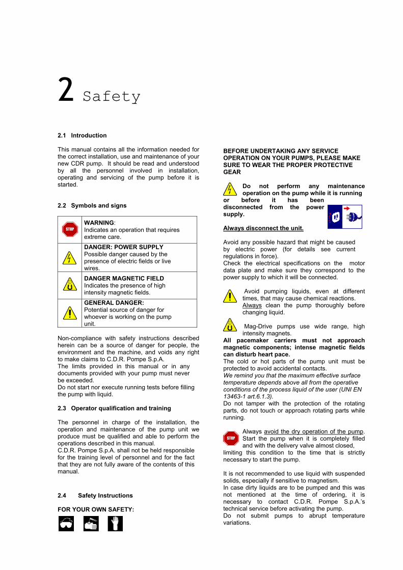
2.2 Symbols and signs WARNING:
Indicates an operation that requires extreme care.
DANGER: POWER SUPPLY Possible danger caused by the presence of electric fields or live wires.
DANGER MAGNETIC FIELD Indicates the presence of high intensity magnetic fields.
GENERAL DANGER: Potential source of danger for whoever is working on the pump unit.
STOP Always disconnect the unit.
Avoid any possible hazard that might be caused by electric power (for details see current regulations in force). Check the electrical specifications on the motor data plate and make sure they correspond to the power supply to which it will be connected.
Avoid pumping liquids, even at different times, that may cause chemical reactions. Always clean the pump thoroughly before changing liquid.
Mag-Drive pumps use wide range, high intensity magnets.
Non-compliance with safety instructions described herein can be a source of danger for people, the environment and the machine, and voids any right to make claims to C.D.R. Pompe S.p.A.
All pacemaker carriers must not approach magnetic components; intense magnetic fields can disturb heart pace. The cold or hot parts of the pump unit must be protected to avoid accidental contacts. The limits provided in this manual or in any
documents provided with your pump must never be exceeded.
We remind you that the maximum effective surface temperature depends above all from the operative conditions of the process liquid of the user (UNI EN 13463-1 art.6.1.3).
Do not start nor execute running tests before filling the pump with liquid. Do not tamper with the protection of the rotating
parts, do not touch or approach rotating parts while running.
2.3 Operator qualification and training The personnel in charge of the installation, the operation and maintenance of the pump unit we produce must be qualified and able to perform the operations described in this manual.
Always avoid the dry operation of the pump. Start the pump when it is completely filled and with the delivery valve almost closed,
STOP
C.D.R. Pompe S.p.A. shall not be held responsible for the training level of personnel and for the fact that they are not fully aware of the contents of this manual.
limiting this condition to the time that is strictly necessary to start the pump. It is not recommended to use liquid with suspended solids, especially if sensitive to magnetism.
In case dirty liquids are to be pumped and this was not mentioned at the time of ordering, it is necessary to contact C.D.R. Pompe S.p.A.’s technical service before activating the pump.
2.4 Safety Instructions FOR YOUR OWN SAFETY:
Do not submit pumps to abrupt temperature variations.

MIEN016-00
®
STOP Clean the pump before performing
service on it!
Corrosive and dangerous liquids contained in the pump could present a thread to your safety!
After service, start the pump again following all the safety instructions described in chapter 6 “Starting and stopping”.
2.5 Noise level STN 4/6/10 pumps, including the motor, in normal operating conditions (Qopt) produces a sound level equal or less than 80 dBA.
The major sources of noise are: liquid turbulence in
the plant, cavitation or any other abnormal operation that does not depend on the manufacturer. The operator must provide for suitable protective means if the sources of noise should produced a harmful level for operators and for the environment (in compliance with current regulations).
2.6 Modifications and Spare parts Any changes concerning the service of the pump as
originally purchased, can be executed only after written approval from C.D.R. Pompe S.p.A.
It is recommended to use only genuine CDR spare
parts and approved accessories. The use of non-original spare parts or non approved accessories will void warranty and removes any responsibility on our behalf for any damage caused to people or things.
CDR Pompe S.p.A. - STN 4 / 6 / 10 Uaer Manual Page - 9

3 Packing & transporting the pump
3 Packing & transporting the pump
3.1 Packaging 3.1 Packaging C.D.R. Pompe S.p.A. pumps or pumping units are normally packed either in cartons (maximum dimensions 800x600x400mm) held in place by foam, or fixed on pallets and wrapped with plastic film. In case of pumps ordered without electric motor, they are packed with the external magnetic core loose, which is kept in the packaging, separated from the pump and protected with foam/padding. Special packaging according to customer’s request are available on demand to suit the type and means of transport. Packaging must be opened and handled according to the instructions shown on it.
C.D.R. Pompe S.p.A. pumps or pumping units are normally packed either in cartons (maximum dimensions 800x600x400mm) held in place by foam, or fixed on pallets and wrapped with plastic film. In case of pumps ordered without electric motor, they are packed with the external magnetic core loose, which is kept in the packaging, separated from the pump and protected with foam/padding. Special packaging according to customer’s request are available on demand to suit the type and means of transport. Packaging must be opened and handled according to the instructions shown on it. To ensure that the crate, cartons or pallets are handled and lifted properly, read the symbols on the package. The following legend provides explanations for this purpose:
To ensure that the crate, cartons or pallets are handled and lifted properly, read the symbols on the package. The following legend provides explanations for this purpose:
3.2 Shipping and Receiving 3.2 Shipping and Receiving The goods we deliver undergo a control procedure and are approved before being released. It is, however, advisable to follow these prescriptions in any case.
The goods we deliver undergo a control procedure and are approved before being released. It is, however, advisable to follow these prescriptions in any case. The contents of each package are described in the packing-list or in the delivery note. They must be checked carefully when they are received.
The contents of each package are described in the packing-list or in the delivery note. They must be checked carefully when they are received. At the moment of their receipt and possibly with the carrier present, check the integrity of the goods and packaging should be checked.
At the moment of their receipt and possibly with the carrier present, check the integrity of the goods and packaging should be checked.
Any claim must be made immediately notifying the carriers and making them sign the claim.
Any claim must be made immediately notifying the carriers and making them sign the claim. In addition, check that the delivery is equivalent to the order specifications (number and type of goods).
In addition, check that the delivery is equivalent to the order specifications (number and type of goods).
TOP TOP
FRAGILE FRAGILE
KEEP DRY KEEP DRY VOID MOISTURE VOID MOISTURE
3.3 Storage 3.3 Storage
In case of storage, the pump must be placed in a dry, covered place and stored in its original packaging or equivalent protection.
In case of storage, the pump must be placed in a dry, covered place and stored in its original packaging or equivalent protection.
STOP
The protecting caps and lids must be kept on the pump flanges until it is installed. The protecting caps and lids must be kept on the pump flanges until it is installed. If the pump needs to be stored for long periods and/or in particularly severe environmental conditions, it is recommended to seal the pump packaging and use some hygroscopic substance (silica gel) to prevent moist damages.
If the pump needs to be stored for long periods and/or in particularly severe environmental conditions, it is recommended to seal the pump packaging and use some hygroscopic substance (silica gel) to prevent moist damages.

MIEN016-00
®
4 Structural description 4.1 Description The STN 4/6/10 pumps are centrifugal, single-stage type with magnetic coupling, in close-coupled version, made from moulded thermoplastic material. 4.2 Construction and Operating The main feature of these pumps is the transmission of movement by means of a magnetic coupling. Fig. 1
The outer magnetic unit (8), connected to the motor shaft transmits torque to the inner magnetic core-impeller group (6), the magnetic field generates impeller rotation without physical contact. The beaker (7) is fitted between the two cores sealing hermetically the liquid pumped by the atmosphere (see figure 1).
b
STN 4 PP / PVDF
POS.
PARTDESCRIPTION
1
SETSCREWS
2
FRONTCASING
3 4 5 6 7 8 9 10
O - RING SHAFT +RINGS
BEARINGS IMPELLER+INTERNALMAGNET
REARCASING
EXTERNALMAGNET
SCREWS BRACKET
1
2
3
4 44 5
6 7 8
9
10
MATERIALS A2 PPPVDF
EPDMVITON
Al2O3 PTFEC PPPVDFNeFe
PPPVDF
FeNeFeb
PP
1
A2MATERIALI
DESCRIZIONEPARTICOLARI
CORPOANT.
SETVITI
GIRANTE+NUCLEOINTERNO
ALBERO +RALLE
O - RING BOCCOLE NUCLEOESTERNO
CORPOPOST.
VITI LANTERNA
CDR Pompe S.p.A. - STN 4 / 6 / 10 Uaer Manual Page - 11

IMPELLER
THRUSTBEARING
BEARING
1
2 34
5 56
7 8
9
10
11
1213
PTFEC
STN 6-10 PP / PVDF
1
DESCRIZIONEPARTICOLARI
MATERIALI
MATERIALS PPPVDF
A2
SETVITI
CORPOANT.
POS.
PARTDESCRIPTION
SETSCREWS
1
FRONTCASING
2
BOCCOLAFRONTALEGIRANTE
EPDMVITON
Al2O3 PTFEC
ALBERO +RALLE
O - RING
PPPVDF
GIRANTE
SHAFT +RINGS
O - RING
3 4 5
IMPELLER
6 7 8 9
CASINGRING +BUSH
BOCCOLA+ ANELLOCORPO
Al2O3EPDMVITON
PPPVDFNeFeb
NUCLEOINTERNO
INTERNALMAGNET
BOCCOLA
MATERIALS
ALI
DESCRIZIONEPARTICOLARI
PARTDESCRIPTION
POS.
PP
CORPOPOST.
REARCASING
10
PPA2FeFeb
NUCLEOESTERNO
VITI LANTERNA
SCREWSEXTERNALMAGNET
11 12
BRACKET
13
MATERI PVDF Ne
Fig. 2

MIEN016-00
®
5 Installation and assembly 5.1 General Instructions
C.D.R. Pompe S.p.A. shall not be held responsible for any damage to people or objects caused by the incorrect assembly or
assembly performed by unqualified personnel.
Install the pump in a place where servicing can be carried out easily. The brickwork and delivery and suction piping must be prepared in compliance with the dimensions shown in the overall or installation drawings. The diameter of the piping must never be smaller than the suction/delivery inlets of the pump.
Electrical parts that operate in areas in which there is a danger of explosion must comply with current regulations in force;
this must be shown on the motor data plate.
Whenever there is a danger of explosion, follow the prescriptions concerning Ex protection and the test certificate prescriptions.
The certificate must be kept where the machine is used.
If flammable liquids are pumped, provide all pump components with proper grounding: static currents may cause sparks and explosions.
5.2 Installation The pump-motor unit must stand on and be fixed to a sufficiently rigid structure that can support the entire perimeter on which the unit stands. The concrete foundations on a firm bottom are the most satisfactory. Once the pump-motor is in position, adjust level with metal shims between the feet and the surface on which it stands. The shims must be placed in direct contact with the foundation bolts and they must be sufficiently wide to cover the largest possible surface. Check that the feet of the pump-motor unit stand well on each of them. In no case this position must be obtained by tightening the nuts of the foundation bolts too much. The surface on which the foundation stands must be flat and horizontal. If the unit is fitted on a steel structure, make sure that it is supported so that the feet do not warp.
In any case, it is advisable to fit some vibration-dampener fittings between the pump and the brickwork.
STOP As the pump is close-coupled type, pump-motor alignment is not required. 5.3 Plumbing
5.3.1 General Instructions
A pump is generally part of a piping system that can include a number of components such as valves, fittings, filters, expansion joints, instruments, etc. The way the piping is arranged and the positioning of the components has a great influence on operation and the operating life of the pump. The pump cannot be used as a support for the components connected to it. Before connection, remove the pump suction and delivery inlet protections. Fig. 3
5.3.2 Max. Stresses allowed on Nozzles
The forces and momentum transmitted to the pump by the piping system shall never exceed the values reported in the following table
STOP
CDR Pompe S.p.A. - STN 4 / 6 / 10 Uaer Manual Page - 13

a bottom valve in all cases when the static height of the liquid is lower than the suction height of the pump. The suction piping must be without air inlets that are more probable with lone suction lines or if suction occurs with negative head. Critical points in these terms are also the seals between flanges and the seals of the valve stems. Even some small air let into the suction line cause serious operating problems that can make the pump stop.
Torque Z (Nm) X (Nm) Y (Nm)
5 5 5 Forces
Z (N) X (N) Y (N) 50 50 80
The pumps of the STN range can become self-priming if equipped with a priming barrel (for any further information please get in touch with C.D.R. Pompe S.p.A.’s technical service).
The heat expansion of piping requires expansion compensators. Any flanges must be centred before tightening the bolts. DO NOT try to pull or straighten the piping by tightening the bolts of the flanges or threaded fittings.
5.3.5 Instruments
The suction and delivery piping and connected valves or filters must be supported and fastened near to but not on
STOP In order to ensure a reasonable control of the
performance and the conditions of the pump installed, we recommend to use the following instruments:
the pump so that any strain from the pump is not transmitted. The piping must be clean and free from impurities. (welding slag, chip, etc.).
- a pressure-vacuum gauge on the suction piping;
- a pressure-vacuum gauge on the delivery piping. The flow of liquid from the pump must be
as even as possible. It is advisable to avoid any tight bends or drastic reductions of diameters that may cause flow resistance
STOP The pressure intakes must be made on straight pieces of piping at minimum five diameters from the pump inlets. The pressure gauge on delivery must always be fitted between the pump and the cut-off/regulation valve. The output can be read on the pressure, transformed into meters and then compared with the typical curves.
in the plant. In case of diameter reduction, it is advisable to use appropriate conical reductions (possibly eccentric on suction side and concentric on delivery side) at changes of diameter and at a minimum distance from pump inlets of five diameters.
The electric power absorbed by the motor can be measure with watt meters.
The optional instruments can advise of abnormal operating conditions of pumps, such as: valves closed accidentally, missing liquid, overloads, etc. (for any further information please get in touch with C.D.R. Pompe S.p.A.’s technical service).
5.3.3 Delivery Piping A foot-valve and a cut-off/regulation valve are normally fitted on the delivery side. The foot-valve protects the pump from any backflow. The cut-off/regulation valve excludes the pump from the line and adjusts output.
If the temperature of the pumped liquid can be a critical element, provide a thermometer (preferably on suction).
Never adjust flow-rate using the valve on the suction pipe.
STOP
5.4 Motor Connection 5.3.4 Suction Piping The electrical connection must always be
carried out by an expert electrician. The suction piping is very important for the correct operation of the pump-motor group. Compare the power supply with the data plate
specifications and then choose a suitable connection.
The suction piping must be as short and as direct as possible. If a longer suction line is needed, the diameter should be large enough to ensure less flow resistance.
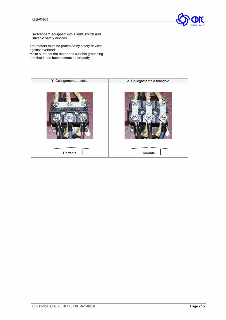
The type of connection is stated on the motor data plate that can be Y (star) or ∆ (Delta), according to the power supply of the motor (see figure).
In any case, suction must be carried out properly avoiding any air locks.
Follow the prescriptions of the local electricity board for the connection.
Pump of STN range are single-stage centrifugal type, thus not self-priming. It will therefore always be necessary to install
STOP
In no case connect the electrical motors directly to mains but also fit in between a suitable electric
MIEN016-00
®
switchboard equipped with a knife switch and suitable safety devices.
The motors must be protected by safety devices against overloads. Make sure that the motor has suitable grounding and that it has been connected properly.
Y Collegamento a stella ∆ Collegamento a triangolo
Corrente
Corrente
CDR Pompe S.p.A. - STN 4 / 6 / 10 Uaer Manual Page - 15
6 Starting and stopping 6.1 General Prescription If the pressure shown on the pressure gauge on the
delivery piping does not increase, turn off the pump immediately and release pressure carefully.
Check manually that the motor is free to turn, moving the motor cooling fan. Repeat the connection procedure (Paragraph 5.3
“Piping connection”). Make sure that the piping is not clogged and is free from residues, solid particles or crystals of product.
If there are changes of flow-rate, head, density, temperature or viscosity of the liquid, stop the pump and get in touch with C.D.R. Pompe S.p.A.’s Technical Service.
In case of alignment on new or modified plants, it is advisable to use temporary “socket” filters?? to fit on the suction line. If the liquid must be kept at a certain temperature to avoid crystallization or solidification, heat piping according to the type of piping or plant needs.
6.3 Re-starting after power cut-off
In case of accidental stopping, make sure that the non-return valve has prevented backflow and check that the motor cooling fan has stopped. Start the pump again following the instructions of paragraph 6.2 “Starting”.
Make sure that the liquid flows regularly into the pump.
The pump and piping connected to it, at least the suction side, must be full of liquid. Any air or gas pocket must be carefully released.
STOP If the pump intakes from a lower level, it can unprime during the standstill and therefore you must check again before starting that the
STOPIn case of suction with negative head, fill the suction piping and check how the bottom valve works. It must guarantee that the liquid must not flow back, emptying therefore the suction pipe with consequent disconnection of the pump.
pump and the suction piping are full of liquid. 6.4 Stopping the Pump
The suction cut-off valve (if any) must be completely open.
It is advisable to close the delivery adjustment/cut-off valve gradually and stop the motor immediately after. Make sure that the motor has an even deceleration.
The cut-off/regulation valve on the delivery side must be almost completely closed.
The motor must turn in the same direction as the arrow shown on the pump. The direction of rotation is always clockwise looking at the
The reverse sequence is not recommendable, especially with larger pumps or longer delivery piping. That is to avoid any problems due to water hammering (ram head). If a suction cut-off valve has been installed, it is advisable to close it completely.
STOP
pump on the motor side; check by starting briefly, then looking at the direction of rotation of the motor fan through the fan lid. If it is wrong, the motor must be stopped immediately. Change the connection to the terminals of the electric motor (Par. 5.4 “Motor connection”) and repeat the procedure described above.
In some cases (e.g. if the pump is used to empty tanks or tank trucks), it may occur that the liquid stops flowing to the pump that is
STOP
still operating. In this case the pump runs without liquid and can be seriously damaged if it is not stopped immediately. If no automatic safety devices (optional) are installed, it is necessary to ensure the constant presence of an operator who can stop the pump promptly and carry out the above-mentioned operations.
Any auxiliary connections must all be connected. 6.2 Starting the Pump Start the electric motor and open the delivery adjustment/cut-off valve gradually until the desired output has been reached.
C.D.R. Pompe S.p.A. is at your complete disposal for the choice of the instrument that is most suitable to avoid operation without liquids.
The pump must not turn more than two or three minutes with delivery closed. A longer operation in these conditions can damage the pump seriously.

MIEN016-00
®
6.5 Periods of long inactivity 6.5.1 The pump remains installed
To avoid substances settling inside the pump because of a long period of inactivity, start the pump for about five minutes periodically (about twice a month). The same applies to pumps in stand by. 6.5.2 The pump is removed and stored
If the pump has to be removed and stored, proceed according to the instructions contained in paragraphs 6.4 “Stopping the pump” and 7.1 “General instructions”. Protect the suction/delivery nozzles (use the caps supplied). When handling the pump, follow the instructions contained in paragraph 7.2 “Transport” and then store the pump as described in paragraph 3.3 “Storage”.
CDR Pompe S.p.A. - STN 4 / 6 / 10 Uaer Manual Page - 17
7 Maintenance
7.1 General information Remove the shaft (4), and the axial thrust shoe
(4) and the O-ring (3) from the isolation-shell (7).
During the warranty period, no operations must be carried out other than by personnel from, or authorized in writing by C.D.R. Pompe S.p.A. All the stages described in this chapter must be carried out by qualified personnel, following all the phases described herein step by step.
Extract the isolation shell (7) from the lantern (10). Remove the motor with the outer magnetic core (8) from the lantern (10) loosening the screws (9).
Each operation carried out on the machine must always be carried out once all the electrical contacts have been disconnected.
Before to extract the outer magnetic core (8) from the motor, loosening the grub screws. The pump-motor unit must be placed in a position
where it cannot be started inadvertently. For STN 6 and 10 proceed as follows (see fig. 2
pag. 12): Before servicing in any way the parts in contact with the pumped liquid, make sure that the pump has been fully emptied and washed.
Dismantle the pump body (2) from the lantern (13), by loosening screws and bolt (1). Pull out the axial thrust shoe (4) from the pump body and the rotating bushes (6) from impeller.
When draining the liquid make sure that there is no danger for people or the environment. Remove the magnets/impeller unit (7/8)
with the rotating bushes (9). 7.2 Handling The shaft, the static and rotating
bushes are usually made from very fragile sintered material and therefore has to be handled with extreme care.
STOPThe pumps/motor pumps weighing over 20 Kg must be transported and positioned using suitable hoisting means. Always use hoisting eyebolts, if any.
The close-coupled pumps, especially those with ADPE motor can have unbalanced masses on the hoisting fittings, therefore transport the units with all the necessary care.
Remove the shaft (5), and the axial thrust shoe (5) and the O-ring (3) from the isolation-shell (10).
While moving the parts avoid any impacts that may damage the pump or the electric motor.
Extract the impeller (7) from the magnetic part (8). Extract the isolation shell (10) from the lantern (13).
7.3 Dismantling the Pump
Remove the motor with the outer magnetic core (11) from the lantern (13) loosening the screws (12).
For STN 4 proceed as follows (see fig. 1 pag. 11): Dismantle the pump body (2) from the lantern (10), by loosening screws and bolt (1).
Before to extract the outer magnetic core (11) from the motor, loosening the grub screws. Pull out the axial thrust shoe (4) from the
shaft. 7.4 Maintenance Schedule Remove the magnets/impeller unit (6) with
the rotating bushes (5). The STN 4, 6 e 10 range pumps have been designed and tested to run for 5000 hours in ideal working conditions.
STOPThe shaft, the static and rotating
bushes are usually made from very fragile sintered material and therefore has to be handled with extreme care.
STOP Please note that is a conservative figure since the actual duty point of your pump can substantially

MIEN016-00
®
modify such value. Additional factors such as intermittent operation, type of pumped liquid and installation in the plant may affect the life of components subject to wear. In any case, C.D.R. Pompe S.p.A. advises to service pumps every year of service, even when used in ideal operating conditions.
7.5 Wear Parts Replacement The components that can affect the correct operation of the pump if not regularly replaced, are: STN 4 - Casing gasket (3) - Rotating bushes (5) - Static shaft (4) - Axial thrust shoe (4) STN 6 / 10 - Casing gasket (3) - Rotating bushes (6 e 9) - Static shaft (5) - Axial thrust shoe (4 e 5) 7.6 Assembly To re-assemble all the wet-end parts and the external magnet proceed in the reverse sequence.
7.6.1 Screws recommended locking torque
Part.n° Pompa / Descrizione Filettatura Coppia di serraggio (Nm)
1 STN 4 / Screws and nuts M5 6 9 STN 4 / Screws and nuts M5 6 1 STN 6 / Screws and nuts M5 6 12 STN 6 / Screws and nuts M6 9 1 STN 10 / Screws and nuts M6 9 12 STN 10 / Screws and nuts M6 9
CDR Pompe S.p.A. - STN 4 / 6 / 10 Uaer Manual Page - 19

8 Troubleshooting 8.1 General Information
The following tables help to identify the causes of any problems during operation or failures of the pump. By consulting table "A" identify on the left column (symptoms) the problem encountered on the right column (causes) the number relevant to the possible causes of malfunctioning. Table "B", by excluding the causes not applicable to the case being examined, allows to identify the causes of the problem. Eliminate the cause of the failure. If the causes encountered are those marked with #, we advise to get in touch with our after sales service available for any doubt or need.
Warning:
In compliance with the Italian law 626/94 concerning safety, our service centre will not repair or work on pumps and components that have not been perfectly cleaned. IN ANY CASE We regret that we shall be forced to return any pumps that, in our indisputable opinion, are not sufficiently clean.
STOP
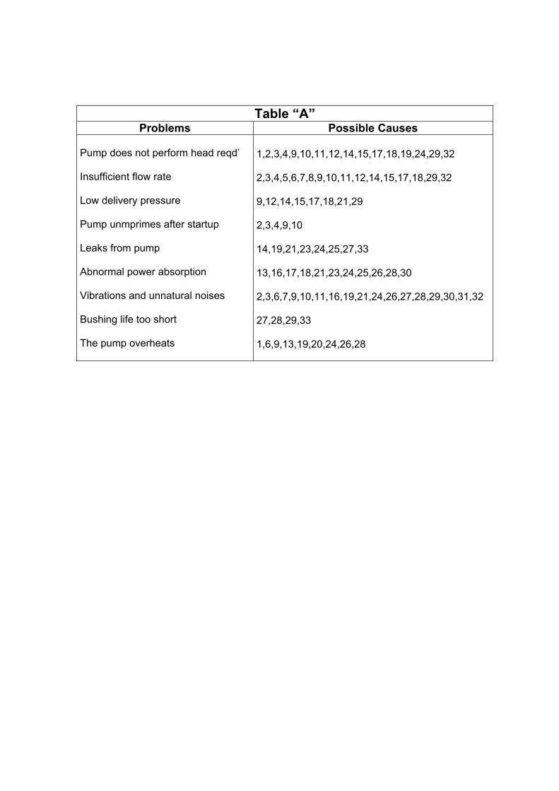
Table “A” Problems Possible Causes
Pump does not perform head reqd’ Insufficient flow rate Low delivery pressure Pump unmprimes after startup Leaks from pump Abnormal power absorption Vibrations and unnatural noises Bushing life too short The pump overheats
1,2,3,4,9,10,11,12,14,15,17,18,19,24,29,32 2,3,4,5,6,7,8,9,10,11,12,14,15,17,18,29,32 9,12,14,15,17,18,21,29 2,3,4,9,10 14,19,21,23,24,25,27,33 13,16,17,18,21,23,24,25,26,28,30 2,3,6,7,9,10,11,16,19,21,24,26,27,28,29,30,31,32 27,28,29,33 1,6,9,13,19,20,24,26,28

Table “B” 1 2 3 4 5 6 7 8 9 10 11 12 13 14 15# 16 17# 18# 19 20 21 22# 23# 24# 25# 26 27 28 29 30 31 32# 33
The Pump is not primed
Suction height too high
Suction piping or pump not completely full of liquid
Suction piping with air pockets
Insufficient suction pressure
Vapour pressure is too high
Suction piping has too high friction losses
Insufficient suction head
Too much air or gas in the pumped liquid
Suction piping not sealed
Bottom valve not sealed or clogged
Low rotation speed
High rotation speed
Wrong direction of rotation
The plant head is higher than the pump
The plant head is lower than the pump
Liquid with density differing from the expected one
Liquid with viscosity differing from the expected one
Operation without liquid -dry running-
Operating flow rate too low
Operating flowrate too high -pump cavitates-
Material not suitable for pumped liquid
Pumped liquid with suspended solid substances
Liquid temperature too high
Liquid temperature too low
Insufficient pressure or bushes flushing -lubrication-
Shaft is not straight
Static and rotating parts rubbing
Damaged impeller
Inner bushes worn or damaged
Rotating unit out of balance
Magnetic coupling damaged or insufficient
Wrong assembly or with dirt

MIEN016-00
®
9 Tables and charts 9.1 Features Table
FEATURES DESCRIPTION
Pump Type Close Coupled STN with B3/B5 frame drive
Materials PP-GF / PVDF-CF
Pumped Liquids CORROSIVE, INFLAMABLE AND TOXIC LIQUIDS
Performance Limitations Q max = 12 m3/h -> H max = 12 mcl
Drives 0,12 Kw ( size 56 ) -> 0,55Kw ( size 71 )
Temperature Range
0°C -> +70°C PP-GF 0°C -> +80°C PVDF-CF
System Pressure Ratings
STN 4/6/10 PP-GF = PN4 (20°C) - PN2 (70°C) STN 4/6/10 PVDF-CF = PN4 (20°C) - PN2 (80°C)
Viscosity 200 cSt max
Solids 2 % max concentration in weight Hardness 800 Vk / Size 150 µm
CDR Pompe S.p.A. - STN 4 / 6 / 10 Uaer Manual Page - 23

O
Q
M
I
ROTAZIONE
DIMENSIONI - mm -
A B C D E F G H I L M N
91G 63 BSTN 6 84 143 1880100 63 59 103/4FPT46
100G 71 BSTN 10 110 180 20112 90 71 70 9 1 1/2 FPT
1FPT45
1FPT
DN
s
VZ
U
G
F
H
DNd
RS
T
P
A N D
B L
C
E
FLANGES - FLANGIATUREDIN PN 10
NOTE : PUMPS AVAILABLE THREADED OR FLANGED. DIRECTION OF ROTATION IS COUNTER CLOCKWISE AS SEEN WHEN FACING THE MOTOR.
DNdDNs
O P Q
R S T U V Z
25 20
1FPT
1/2FPT
40 140
75 105 14 14 85 115
__71 56 39 34178 35 80 1209011576G 56 BSTN 4
183
204
__
__ ____ __ __ __ __ __
STN 4-6-10 PP-PVDF
FLANGES DIMENSIONS - mm -
0.12
0.25
0.55 45 160
85 115 14 18 110 150 40 25STN 10
STN 6
STN 4
PUMPTYPE
ROTATION
LE POMPE SONO DISPONIBILI SENZA O CON FLANGIATURA. SENSO ROTAZIONE MOTORE ANTIORARIO GUARDANDO LA POMPA DAL LATO MOTORE
DIMENSIONI FLANGE - mm -POMPATIPO
KwDIMENSIONS - mm -
PUMPTYPE
POMPATIPO
FLANGEMOTOREB3 - B5
MOTORFLANGEB3 - B5

MIEN016-00
®
Notes
CDR Pompe S.p.A. - STN 4 / 6 / 10 Uaer Manual Page - 25

CDR POMPE S.p.A. Via P. Togliatti, 26/a I-20030 Senago, MI Tel.: +39 02 990 1941 Fax: +39 02 998 0606
®®
MMaannuuaallee iinnssttaallllaazziioonnee,,uussoo ee mmaannuutteennzziioonnee