stm32cubemx, one wire and ds18b20stm32cubemx, one wire and ds18b20 after we know how rtc ds1307 and...
TRANSCRIPT

STM32CubeMX, ONE WIRE and DS18B20
After we know how RTC DS1307 and EEPROM
AT24C128 can be written and read out, we now will work at
the next pages with the digital thermometer DS18B20 from
Dallas.
One can communicate with this IC via a 1-Wire with respect to
GND.
We use a STM32F103C8 – mounted on a Black Pill – to control
the blue board with its three IC’s.
A program framework is generated by STM32CubeMX first.

The Black Pill is on the lower side connected with a
ST Link V2 programmer for STM8 and STM32.
The upper USB connector of the Black Pill is used to
transfer all of the DS18B20 data to a terminal program.
STM32CubeMX
Launch STM32CubeMX, select
and
Then do the following:


Atollic TrueSTUDIO
Copy the project ow3 into the workspace of TrueSTUDIO,
select and activate
Inside TrueSTUDIO we do the following:
In main.c we change
static void MX_GPIO_Init(void) { . . . HAL_GPIO_WritePin(GPIOA, GPIO_PIN_9, GPIO_PIN_RESET); . . . GPIO_InitStruct.Mode = GPIO_MODE_OUTPUT_PP; . . . GPIO_InitStruct.Speed = GPIO_SPEED_FREQ_LOW;
into
HAL_GPIO_WritePin(GPIOA, GPIO_PIN_9, GPIO_PIN_SET); GPIO_InitStruct.Mode = GPIO_MODE_OUTPUT_OD; //open drain GPIO_InitStruct.Speed = GPIO_SPEED_FREQ_HIGH;
so we will not forget it – for the moment it is not important.
Test USB communication
Include the gray highlighted C-code:
#include "main.h"
#include "usb_device.h"
#include "usbd_cdc_if.h"//By reason of: CDC_Transmit_FS(uint8_t*, uint16_t);
void SystemClock_Config(void);
static void MX_GPIO_Init(void);
void USB_Info(char*);
uint16_t slen(const char*);
void add_txt(char* , char* );
int main(void)
{
HAL_Init();
SystemClock_Config();
MX_GPIO_Init();
MX_USB_DEVICE_Init();

while (1){
USB_Info("Hallo");
HAL_Delay(1000);
}
}
uint16_t slen(const char* s) {
uint16_t i;
for (i = 0; s[i] != 0; i++);
return i;//s[0] not 0 then i=1;
}
void add_txt(char* out, char* in) {
while (*out != 0) out++;
while (*in != 0) {
*out++ = *in++;
}
*out = 0;
}
void USB_Info(char *str)
{
char txt[64] = {};
add_txt( txt, str);
add_txt( txt, "\n\r");
CDC_Transmit_FS((uint8_t *)txt, slen(txt));
}
void SystemClock_Config(void)
{
RCC_OscInitTypeDef RCC_OscInitStruct = {0};
RCC_ClkInitTypeDef RCC_ClkInitStruct = {0};
RCC_PeriphCLKInitTypeDef PeriphClkInit = {0};
RCC_OscInitStruct.OscillatorType = RCC_OSCILLATORTYPE_HSE;
RCC_OscInitStruct.HSEState = RCC_HSE_ON;
RCC_OscInitStruct.HSEPredivValue = RCC_HSE_PREDIV_DIV1;
RCC_OscInitStruct.HSIState = RCC_HSI_ON;
RCC_OscInitStruct.PLL.PLLState = RCC_PLL_ON;
RCC_OscInitStruct.PLL.PLLSource = RCC_PLLSOURCE_HSE;
RCC_OscInitStruct.PLL.PLLMUL = RCC_PLL_MUL9;
if (HAL_RCC_OscConfig(&RCC_OscInitStruct) != HAL_OK) Error_Handler();
RCC_ClkInitStruct.ClockType = RCC_CLOCKTYPE_HCLK|RCC_CLOCKTYPE_SYSCLK
|RCC_CLOCKTYPE_PCLK1|RCC_CLOCKTYPE_PCLK2;
RCC_ClkInitStruct.SYSCLKSource = RCC_SYSCLKSOURCE_PLLCLK;
RCC_ClkInitStruct.AHBCLKDivider = RCC_SYSCLK_DIV1;
RCC_ClkInitStruct.APB1CLKDivider = RCC_HCLK_DIV2;
RCC_ClkInitStruct.APB2CLKDivider = RCC_HCLK_DIV1;
if (HAL_RCC_ClockConfig(&RCC_ClkInitStruct, FLASH_LATENCY_2) != HAL_OK)
Error_Handler();
PeriphClkInit.PeriphClockSelection = RCC_PERIPHCLK_USB;
PeriphClkInit.UsbClockSelection = RCC_USBCLKSOURCE_PLL_DIV1_5;
if (HAL_RCCEx_PeriphCLKConfig(&PeriphClkInit) != HAL_OK) Error_Handler();
}
static void MX_GPIO_Init(void)
{
GPIO_InitTypeDef GPIO_InitStruct = {0};

__HAL_RCC_GPIOD_CLK_ENABLE();
__HAL_RCC_GPIOA_CLK_ENABLE();
HAL_GPIO_WritePin(GPIOA, GPIO_PIN_9, GPIO_PIN_SET);
GPIO_InitStruct.Pin = GPIO_PIN_9;
GPIO_InitStruct.Mode = GPIO_MODE_OUTPUT_OD;
GPIO_InitStruct.Pull = GPIO_NOPULL;
GPIO_InitStruct.Speed = GPIO_SPEED_FREQ_HIGH;
HAL_GPIO_Init(GPIOA, &GPIO_InitStruct);
}
void Error_Handler(void){}
#ifdef USE_FULL_ASSERT
void assert_failed(uint8_t *file, uint32_t line){}
#endif
Save and build the project, put jumper into programming mode
connect the programmer and press
Once the program is flashed, terminate debugging and disconnect the ST-Link.
Put the jumper in RUN mode, and connect USB of Black Pill to the computer

A new Comport
appears
Start a terminal sheet and connect with 2000000 bauds with – in my case
COM12

ONE WIRE and DS18B20
All write time slots must be a minimum of dtwrite ≥ 60µs in duration with a minimum of a dtrecover ≥ 1µs
recovery time between individual write slots. To write a ZERO (GND_LOW) or a ONE (PULLUP_HIGH),
use:
void LH_signal(uint32_t L_time, uint32_t H_time) {
HAL_GPIO_WritePin(GPIOA, GPIO_PIN_9, GPIO_PIN_RESET);
delayus(L_time);//From pullup_HIGH to GND_LOW:---___
HAL_GPIO_WritePin(GPIOA, GPIO_PIN_9, GPIO_PIN_SET);
delayus(H_time);//From GND_LOW to pullup_HIGH:___---
}
void write_bit(uint8_t bit) {
if(bit == 0) LH_signal(60, 5);
else LH_signal(5, 60);
}
together with a DELAY procedure for microseconds:
void delayus(uint32_t us) {
volatile uint32_t counter = 8*us;
while(counter--);
}
Oscilloscope pictures for a Black Pill with a STM32F103, f = 72MHz, prove the result. You will get these
pictures with a little blue highlighted trick:
void LH_show_signal(uint32_t L_time, uint32_t H_time) {
HAL_GPIO_WritePin(GPIOA, GPIO_PIN_9, GPIO_PIN_RESET);
delayus(L_time);//From pullup_HIGH to GND_LOW:---___
HAL_GPIO_WritePin(GPIOA, GPIO_PIN_9, GPIO_PIN_SET);
delayus(H_time);//From GND_LOW to pullup_HIGH:___---
HAL_GPIO_WritePin(GPIOA, GPIO_PIN_9, GPIO_PIN_RESET);
HAL_Delay(1);
HAL_GPIO_WritePin(GPIOA, GPIO_PIN_9, GPIO_PIN_SET);
HAL_Delay(1);
}
int main(void) {
…
while (1){
LH_show_signal(5, 60);//HIGH=1
//LH_show_signal(60, 5);//LOW=0
}
}

To write and read, we need procedures to flip between OUTPUT and INPUT mode:
Let’s put the STM32 in READ mode, to read a ZERO (GND_LOW) or a ONE (PULLUP_HIGH):
Our code is:
uint8_t read_bit(void) {
uint8_t bit = 0;
LH_signal(1, 10);
A9_as_INPUT();
bit = (HAL_GPIO_ReadPin(GPIOA, GPIO_PIN_9) ? 1 : 0);
delayus(40);
A9_as_OUTPUT();
return bit;
}
static void A9_as_OUTPUT(void)
{
GPIO_InitTypeDef GPIO_InitStruct = {0};
HAL_GPIO_WritePin(GPIOA, GPIO_PIN_9, GPIO_PIN_SET);
GPIO_InitStruct.Pin = GPIO_PIN_9;
GPIO_InitStruct.Mode = GPIO_MODE_OUTPUT_OD;
GPIO_InitStruct.Pull = GPIO_NOPULL;
GPIO_InitStruct.Speed = GPIO_SPEED_FREQ_HIGH;
HAL_GPIO_Init(GPIOA, &GPIO_InitStruct);
}
static void A9_as_INPUT(void)
{
GPIO_InitTypeDef GPIO_InitStruct = {0};
HAL_GPIO_WritePin(GPIOA, GPIO_PIN_9, GPIO_PIN_SET);
GPIO_InitStruct.Pin = GPIO_PIN_9;
GPIO_InitStruct.Mode = GPIO_MODE_INPUT;
GPIO_InitStruct.Pull = GPIO_NOPULL;
HAL_GPIO_Init(GPIOA, &GPIO_InitStruct);
}

Power-On and Reset
After power-on we need a reset. “If the bus is held low for more than 480µs, all DS18B20 on the bus will be
reset.” With the green part GND_LOW, a DS18B20 signals that it is present.
You can test this – if you want – with:
void get_presence(void) {
uint8_t flag = 1;
LH_signal(500, 0);
A9_as_INPUT();
delayus(60);//look for GND_LOW = DS18B20 exists, and set flag = 1
flag = (HAL_GPIO_ReadPin(GPIOA, GPIO_PIN_9) ? 0 : 1); //not ?1:0
A9_as_OUTPUT();
delayus(400);
if(flag) USB_Info("DS18B20 present");
else USB_Info("DS18B20 not present");
HAL_Delay(1000);
}
Otherwise – there is only one working DS18B20 – use for a RESET:
int main(void) {
…
while (1){
get_presence();
}
}
void reset(void) {
LH_signal(500, 500);
}

64-BIT Lasered ID
“Each DS18B20 contains a unique 64-bit code stored in ROM. The least significant 8 bits of the ROM code
contain the DS18B20’s 1-Wire family code: 28h. The next 48 bits contain a unique serial number. The
most significant 8 bits contain a cyclic redundancy check (CRC) byte that is calculated from the first 56 bits of
the ROM code.”
You can read the 8 byte ID with these lines of code:
void get_ID(void) {
uint8_t id_data[] = {0,0,0,0,0,0,0,0};//8 Byte
reset();
write_byte(0x33);//Read ROM [33h] command
for (uint8_t i = 0; i < 8; i++)
id_data[i] = read_byte();//id_data[0] = 40 = 0x28
for (uint8_t i = 0; i < 8; i++){
USB_Info_tutu("id", i, " = ", id_data[i]);
HAL_Delay(200);
}
}
int main(void) {
…
while (1){
get_ID();
USB_Info("-------------------------");
HAL_Delay(1000);
}
}

Read Temperature
“After the Convert T command the DS18B20 will respond by transmitting 0 while the temperature conversion
is in progress and 1 when the conversion is done.”
The reset value of resolution is 12 bit. At first we are not interressed in negative temperatures. If we factor out
16
12 4 , we get usual register bit values, and the temperature is given by: T = (MS << 8) + LS) / 16.0;
During the conversion we have to wait until the 1-wire is again in PULLUP_HIGH.
We do that in C-code with:
void A9_wait_for_1(uint32_t time) {
A9_as_INPUT();
delayus(time);
while(HAL_GPIO_ReadPin(GPIOA, GPIO_PIN_9) == 0);
A9_as_OUTPUT();
}
float get_temperature(void) {
uint8_t pad_data[] = {0,0,0,0,0,0,0,0,0};//9 Byte
reset();
write_byte(0xCC);//Skip ROM [CCh]
write_byte(0x44);//Convert Temperature [44h]
A9_wait_for_1(20);
reset();
write_byte(0xCC);//Skip ROM [CCh]
write_byte(0xBE);//Read Scratchpad [BEh]
for (uint8_t i = 0; i < 9; i++)
pad_data[i] = read_byte();
//factor out 1/16 and remember 1/16 != 1/16.0
return ((pad_data[1] << 8) + pad_data[0])/16.0;
//DS18B20.pdf: val of bit0: 2^(-4) = 1/16
}

In the presence of multiple DS18B20, the ID helps us to distinguish and address them. Our chip has the ID
sequence – see above: 40 25 0 0 120 2 0 136
Instead of a Skip ROM [CCh] we can send this ID to communicate with our DS18B20:
void send_ID(void) {
uint8_t id_data[] = {40,25,0,0,120,2,0,136};//8 Byte ID
reset();
write_byte(0x55);//Match ROM [55h]
for (uint8_t i = 0; i < 8; i++)
write_byte(id_data[i]);//id_data[0] = 40 = 0x28
}
float get_temperature_with_ID(void) {
uint8_t pad_data[] = {0,0,0,0,0,0,0,0,0};//9 Byte
reset();
send_ID();
write_byte(0x44);//Convert Temperature [44h]
A9_wait_for_1(20);
reset();
send_ID();
write_byte(0xBE);//Read Scratchpad [BEh]
for (uint8_t i = 0; i < 9; i++)
pad_data[i] = read_byte();//factor out 1/16 and remember 1/16 != 1/16.0
return ((pad_data[1] << 8) + pad_data[0])/16.0;//DS18B20.pdf: val of bit0: 2^(-4) = 1/16
}
Try the C-code with a correct and a
wrong ID and note the difference in
your terminal window.
int main(void) {
…
while (1){
USB_Info_tf("T(C) = ", get_temperature());
HAL_Delay(500);
}
}
int main(void) {
…
while (1){
USB_Info_tf("T(C) = ", get_temperature_with_ID());
HAL_Delay(500);
}
}
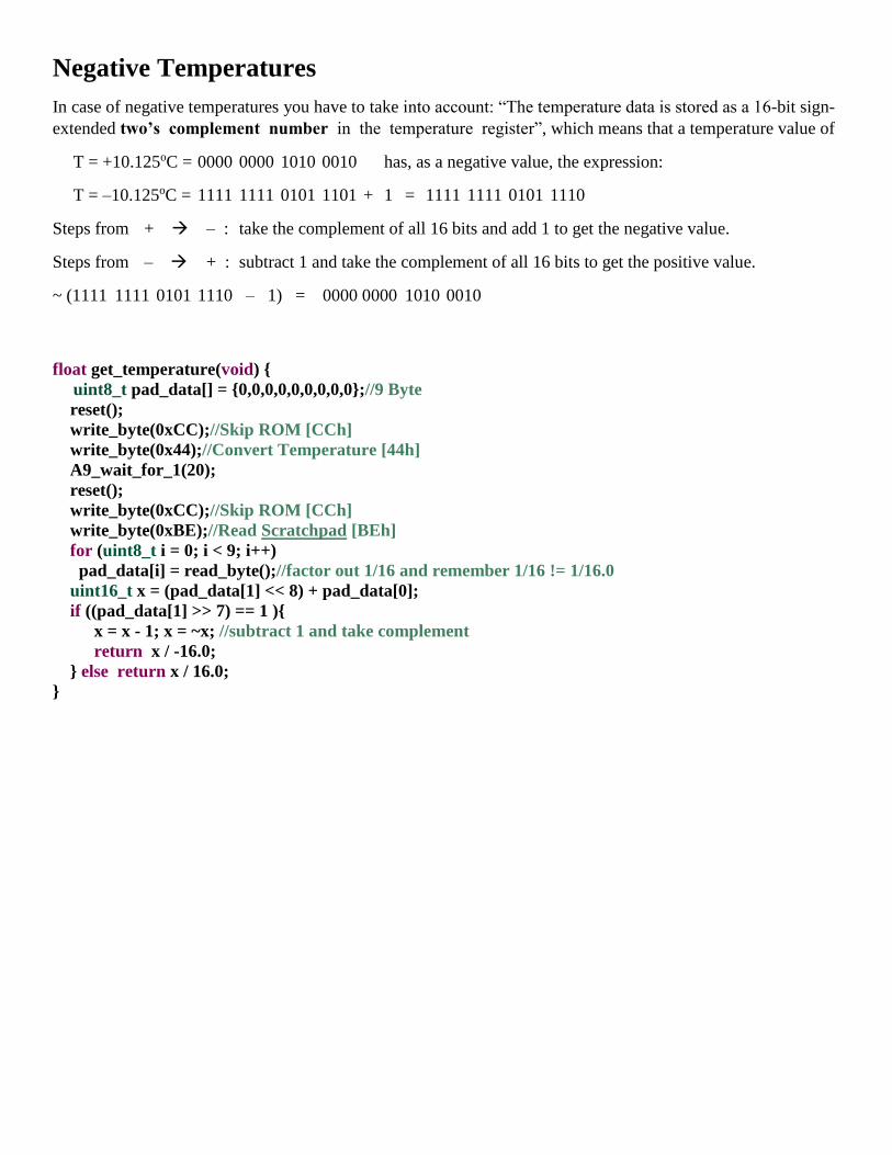
Negative Temperatures
In case of negative temperatures you have to take into account: “The temperature data is stored as a 16-bit sign-
extended two’s complement number in the temperature register”, which means that a temperature value of
T = +10.125oC = 0000 0000 1010 0010 has, as a negative value, the expression:
T = –10.125oC = 1111 1111 0101 1101 + 1 = 1111 1111 0101 1110
Steps from + – : take the complement of all 16 bits and add 1 to get the negative value.
Steps from – + : subtract 1 and take the complement of all 16 bits to get the positive value.
~ (1111 1111 0101 1110 – 1) = 0000 0000 1010 0010
float get_temperature(void) {
uint8_t pad_data[] = {0,0,0,0,0,0,0,0,0};//9 Byte
reset();
write_byte(0xCC);//Skip ROM [CCh]
write_byte(0x44);//Convert Temperature [44h]
A9_wait_for_1(20);
reset();
write_byte(0xCC);//Skip ROM [CCh]
write_byte(0xBE);//Read Scratchpad [BEh]
for (uint8_t i = 0; i < 9; i++)
pad_data[i] = read_byte();//factor out 1/16 and remember 1/16 != 1/16.0
uint16_t x = (pad_data[1] << 8) + pad_data[0];
if ((pad_data[1] >> 7) == 1 ){
x = x - 1; x = ~x; //subtract 1 and take complement
return x / -16.0;
} else return x / 16.0;
}

Finally, the entire main.c file. The yellow highlighted code is not from STM32CubeMX
#include "main.h"
#include "usb_device.h"
#include "usbd_cdc_if.h"//By reason of: CDC_Transmit_FS(uint8_t*, uint16_t);
void SystemClock_Config(void);
static void MX_GPIO_Init(void);
uint16_t slen(const char*);
void add_txt(char* , char* );
char* my_utoa(unsigned, char*);
char* my_ftoa(float, char*);
void USB_Info(char*);
void USB_Info_tu(char*, unsigned);
void USB_Info_tutu(char*, unsigned, char*, unsigned);
void USB_Info_tf(char*, float);
void delayus(uint32_t us) {
volatile uint32_t counter = 8*us;
while(counter--);
}
void LH_signal(uint32_t L_time, uint32_t H_time) {
HAL_GPIO_WritePin(GPIOA, GPIO_PIN_9, GPIO_PIN_RESET);
delayus(L_time);//From pullup_HIGH to GND_LOW:---___
HAL_GPIO_WritePin(GPIOA, GPIO_PIN_9, GPIO_PIN_SET);
delayus(H_time);//From GND_LOW to pullup_HIGH:___---
}
void write_bit(uint8_t bit) {
if(bit == 0) LH_signal(60, 5);
else LH_signal(5, 60);
}
void write_byte(uint8_t data) {
for (uint8_t i = 0; i < 8; i++)
write_bit(data >> i & 1);
}
static void A9_as_INPUT(void)
{
GPIO_InitTypeDef GPIO_InitStruct = {0};
HAL_GPIO_WritePin(GPIOA, GPIO_PIN_9, GPIO_PIN_SET);
GPIO_InitStruct.Pin = GPIO_PIN_9;
GPIO_InitStruct.Mode = GPIO_MODE_INPUT;
GPIO_InitStruct.Pull = GPIO_NOPULL;
HAL_GPIO_Init(GPIOA, &GPIO_InitStruct);
}
static void A9_as_OUTPUT(void)
{
GPIO_InitTypeDef GPIO_InitStruct = {0};

HAL_GPIO_WritePin(GPIOA, GPIO_PIN_9, GPIO_PIN_SET);
GPIO_InitStruct.Pin = GPIO_PIN_9;
GPIO_InitStruct.Mode = GPIO_MODE_OUTPUT_OD;
GPIO_InitStruct.Pull = GPIO_NOPULL;
GPIO_InitStruct.Speed = GPIO_SPEED_FREQ_HIGH;
HAL_GPIO_Init(GPIOA, &GPIO_InitStruct);
}
uint8_t read_bit(void) {
uint8_t bit = 0;
LH_signal(1, 10);
A9_as_INPUT();
bit = (HAL_GPIO_ReadPin(GPIOA, GPIO_PIN_9) ? 1 : 0);
delayus(40);
A9_as_OUTPUT();
return bit;
}
uint8_t read_byte(void) {
uint8_t data = 0;
for (uint8_t i = 0; i < 8; i++)
data += read_bit() << i;
return data;
}
void A9_wait_for_1(uint32_t time) {
A9_as_INPUT();
delayus(time);
while(HAL_GPIO_ReadPin(GPIOA, GPIO_PIN_9) == 0);
A9_as_OUTPUT();
}
void reset(void) {
LH_signal(500, 500);
}
void get_presence(void) {
uint8_t flag = 1;
LH_signal(500, 0);
A9_as_INPUT();
delayus(60);//look for GND_LOW = DS18B20 exists
flag = (HAL_GPIO_ReadPin(GPIOA, GPIO_PIN_9) ? 0 : 1);//not ?1:0
A9_as_OUTPUT();
delayus(400);
if(flag) USB_Info("DS18B20 present");
else USB_Info("DS18B20 not present");
HAL_Delay(1000);
}
float get_temperature(void) {
uint8_t pad_data[] = {0,0,0,0,0,0,0,0,0};//9 Byte
reset();

write_byte(0xCC);//Skip ROM [CCh]
write_byte(0x44);//Convert Temperature [44h]
A9_wait_for_1(20);
reset();
write_byte(0xCC);//Skip ROM [CCh]
write_byte(0xBE);//Read Scratchpad [BEh]
for (uint8_t i = 0; i < 9; i++)
pad_data[i] = read_byte();//factor out 1/16 and remember 1/16 != 1/16.0
uint16_t x = (pad_data[1] << 8) + pad_data[0];
if ((pad_data[1] >> 7) == 1 ){
x -= 1; x = ~x;
return x / -16.0;
} else return x / 16.0;
}
void get_scratchpad(void) {
uint8_t pad_data[] = {0,0,0,0,0,0,0,0,0};//9 Byte
reset();
write_byte(0xCC);//Skip ROM [CCh]
write_byte(0x44);//Convert Temperature [44h]
A9_wait_for_1(20);
reset();
write_byte(0xCC);//Skip ROM [CCh]
write_byte(0xBE);//Read Scratchpad [BEh]
for (uint8_t i = 0; i < 9; i++)
pad_data[i] = read_byte();//factor out 1/16 and remember 1/16 != 1/16.0
for (uint8_t i = 0; i < 9; i++){
USB_Info_tutu("pad", i, " = ", pad_data[i]);
HAL_Delay(200);
}
}
void get_ID(void) {
uint8_t id_data[] = {0,0,0,0,0,0,0,0};//8 Byte
reset();
write_byte(0x33);//Read ROM [33h]
for (uint8_t i = 0; i < 8; i++)
id_data[i] = read_byte();//id_data[0] = 40 = 0x28
for (uint8_t i = 0; i < 8; i++){
USB_Info_tutu("id", i, " = ", id_data[i]);
HAL_Delay(200);
}
}
void send_ID(void) {
uint8_t id_data[] = {40,25,0,0,120,2,0,136};//8 Byte ID
reset();
write_byte(0x55);//Match ROM [55h]
for (uint8_t i = 0; i < 8; i++)
write_byte(id_data[i]);//id_data[0] = 40 = 0x28
}

float get_temperature_with_ID(void) {
uint8_t pad_data[] = {0,0,0,0,0,0,0,0,0};//9 Byte
reset();
send_ID();
write_byte(0x44);//Convert Temperature [44h]
A9_wait_for_1(20);
reset();
send_ID();
write_byte(0xBE);//Read Scratchpad [BEh]
for (uint8_t i = 0; i < 9; i++)
pad_data[i] = read_byte();//factor out 1/16 and remember 1/16 != 1/16.0
return ((pad_data[1] << 8) + pad_data[0])/16.0;//DS18B20.pdf: val of bit0: 2^(-4) = 1/16
}
int main(void)
{
HAL_Init();
SystemClock_Config();
MX_GPIO_Init();
MX_USB_DEVICE_Init();
while (1){
USB_Info_tf("T(C) = ", get_temperature());
HAL_Delay(500);
}
}
uint16_t slen(const char* s) {
uint16_t i;
for (i = 0; s[i] != 0; i++);
return i;//s[0] not 0 then i=1;
}
void add_txt(char* out, char* in) {
while (*out != 0) out++;
while (*in != 0) {
*out++ = *in++;
}
*out = 0;
}
char* my_utoa(unsigned val, char *str)
{
//static char buffer[10];
char* cp = str;
unsigned v;
char c;
v = val;
do {
v /= 10;
cp++;
} while(v != 0);
*cp-- = 0;
do {
c = val % 10;

val /= 10;
c += '0';
*cp-- = c;
} while(val != 0);
return cp;
}
char *my_ftoa(float val, char *str)
{
char *cp; cp=str;
int v, v0, rest, rest0;
char c;
if(val < 0){ // cp=0
val = -val; //cp[0 ][1 ][2][3][4][5][6][7][8][9]
*cp++ = '-'; // [0: -] cp=1
}
v0 = (int)val; v=v0;
//rest0=(int)((val-(int)val)*100000000); rest = rest0;
rest0=(int)((val-(int)val)*10000); rest = rest0;
do {
v /= 10;
cp++;
} while(v != 0);
do {
rest /= 10;
cp++;
} while(rest != 0);
cp++; //wegen ','
*cp-- = 0;
do {
c = rest0 % 10;
rest0 /= 10;
c += '0';
*cp-- = c;
} while(rest0 != 0);
*cp-- = ',';
do {
c = v0 % 10;
v0 /= 10;
c += '0';
*cp-- = c;
} while(v0 != 0);
return cp;
}
void USB_Info(char *str)
{
char txt[64] = {};
add_txt( txt, str);
add_txt( txt, "\n\r");
CDC_Transmit_FS((uint8_t *)txt, slen(txt));
}
void USB_Info_tu(char* t1, unsigned u1)
{

char txt[64] = {}, h[32] = {};
add_txt(txt, t1);
my_utoa(u1, h);
add_txt(txt, h);
add_txt(txt, "\n\r");
CDC_Transmit_FS((uint8_t *)txt, slen(txt));
}
void USB_Info_tutu(char* t1, unsigned u1, char* t2, unsigned u2)
{
char txt[64] = {}, h[32] = {};
add_txt(txt, t1);
my_utoa(u1, h);
add_txt(txt, h);
add_txt(txt, t2);
my_utoa(u2, h);
add_txt(txt, h);
add_txt(txt, "\n\r");
CDC_Transmit_FS((uint8_t *)txt, slen(txt));
}
void USB_Info_tf(char* t1, float u1)
{
char txt[64] = {}, h[32] = {};
add_txt(txt, t1);
my_ftoa(u1, h);
add_txt(txt, h);
add_txt(txt, "\n\r");
CDC_Transmit_FS((uint8_t *)txt, slen(txt));
}
void SystemClock_Config(void)
{
RCC_OscInitTypeDef RCC_OscInitStruct = {0};
RCC_ClkInitTypeDef RCC_ClkInitStruct = {0};
RCC_PeriphCLKInitTypeDef PeriphClkInit = {0};
RCC_OscInitStruct.OscillatorType = RCC_OSCILLATORTYPE_HSE;
RCC_OscInitStruct.HSEState = RCC_HSE_ON;
RCC_OscInitStruct.HSEPredivValue = RCC_HSE_PREDIV_DIV1;
RCC_OscInitStruct.HSIState = RCC_HSI_ON;
RCC_OscInitStruct.PLL.PLLState = RCC_PLL_ON;
RCC_OscInitStruct.PLL.PLLSource = RCC_PLLSOURCE_HSE;
RCC_OscInitStruct.PLL.PLLMUL = RCC_PLL_MUL9;
if (HAL_RCC_OscConfig(&RCC_OscInitStruct) != HAL_OK) Error_Handler();
RCC_ClkInitStruct.ClockType = RCC_CLOCKTYPE_HCLK|RCC_CLOCKTYPE_SYSCLK
|RCC_CLOCKTYPE_PCLK1|RCC_CLOCKTYPE_PCLK2;
RCC_ClkInitStruct.SYSCLKSource = RCC_SYSCLKSOURCE_PLLCLK;
RCC_ClkInitStruct.AHBCLKDivider = RCC_SYSCLK_DIV1;
RCC_ClkInitStruct.APB1CLKDivider = RCC_HCLK_DIV2;
RCC_ClkInitStruct.APB2CLKDivider = RCC_HCLK_DIV1;
if (HAL_RCC_ClockConfig(&RCC_ClkInitStruct, FLASH_LATENCY_2) != HAL_OK)
Error_Handler();
PeriphClkInit.PeriphClockSelection = RCC_PERIPHCLK_USB;
PeriphClkInit.UsbClockSelection = RCC_USBCLKSOURCE_PLL_DIV1_5;

if (HAL_RCCEx_PeriphCLKConfig(&PeriphClkInit) != HAL_OK) Error_Handler();
}
static void MX_GPIO_Init(void)
{
GPIO_InitTypeDef GPIO_InitStruct = {0};
__HAL_RCC_GPIOD_CLK_ENABLE();
__HAL_RCC_GPIOA_CLK_ENABLE();
HAL_GPIO_WritePin(GPIOA, GPIO_PIN_9, GPIO_PIN_SET);
GPIO_InitStruct.Pin = GPIO_PIN_9;
GPIO_InitStruct.Mode = GPIO_MODE_OUTPUT_OD;
GPIO_InitStruct.Pull = GPIO_NOPULL;
GPIO_InitStruct.Speed = GPIO_SPEED_FREQ_HIGH;
HAL_GPIO_Init(GPIOA, &GPIO_InitStruct);
}
void Error_Handler(void){}
#ifdef USE_FULL_ASSERT
void assert_failed(uint8_t *file, uint32_t line){}
#endif
… have fun with STM32!